

ABB M25102 P, M25102 CR, 5102, 5101 P, M25102 A Series Manual
...
M25102xC
M25102xA-xM25102xPx.
M25102xK-x.
M25102xCR.
5102xDN
5101xPx
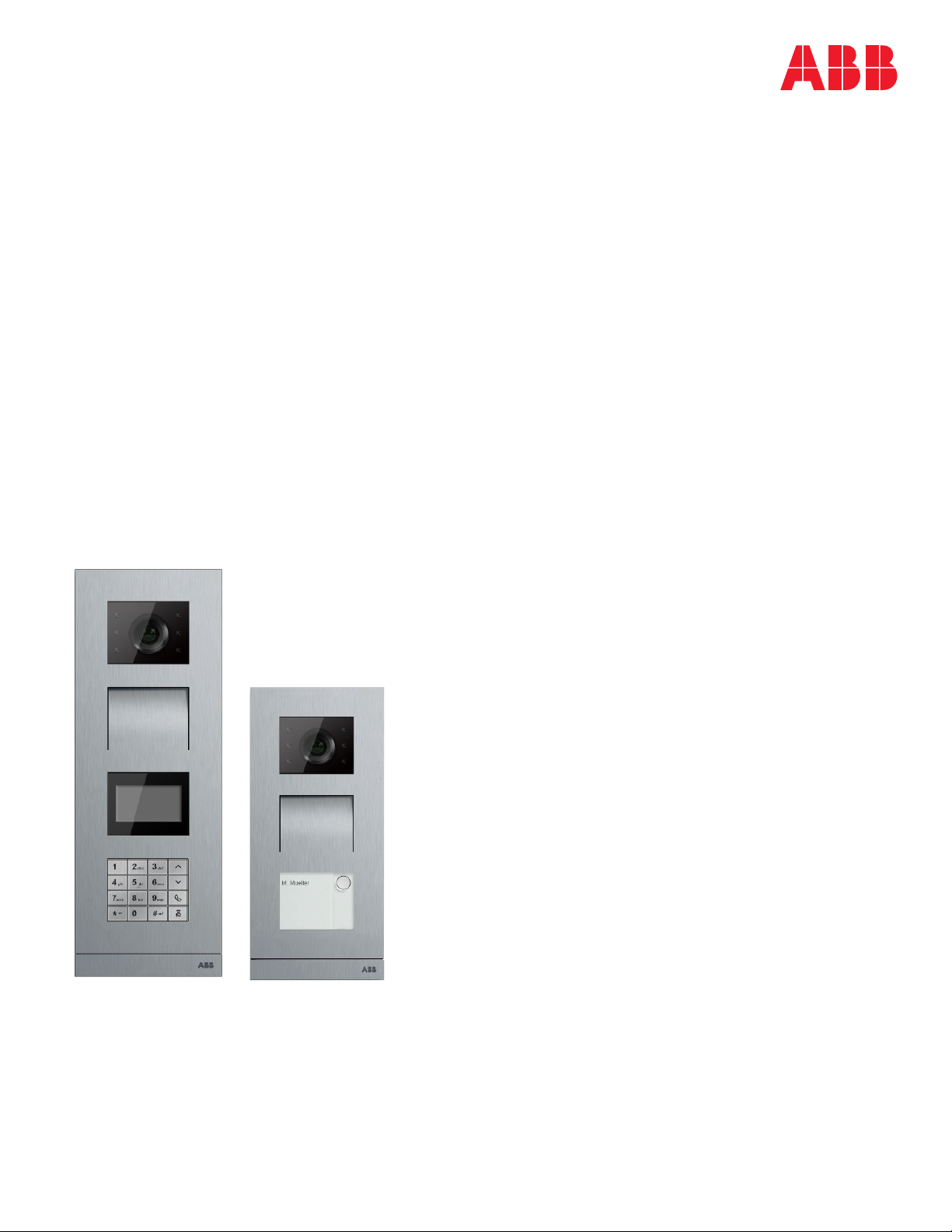
Outdoor station
Pos: 2 /DinA4 - Anleitungen Online/Inhalt/KNX/DoorEntry/83220-AP-xxx/Titelblatt - 83220-AP-xxx - ABB @ 19\mod_1323249806476_15. docx @ 11108 4 @ @ 1
—
VER: 1.3 | 02.20.2017
ABB Welcome®
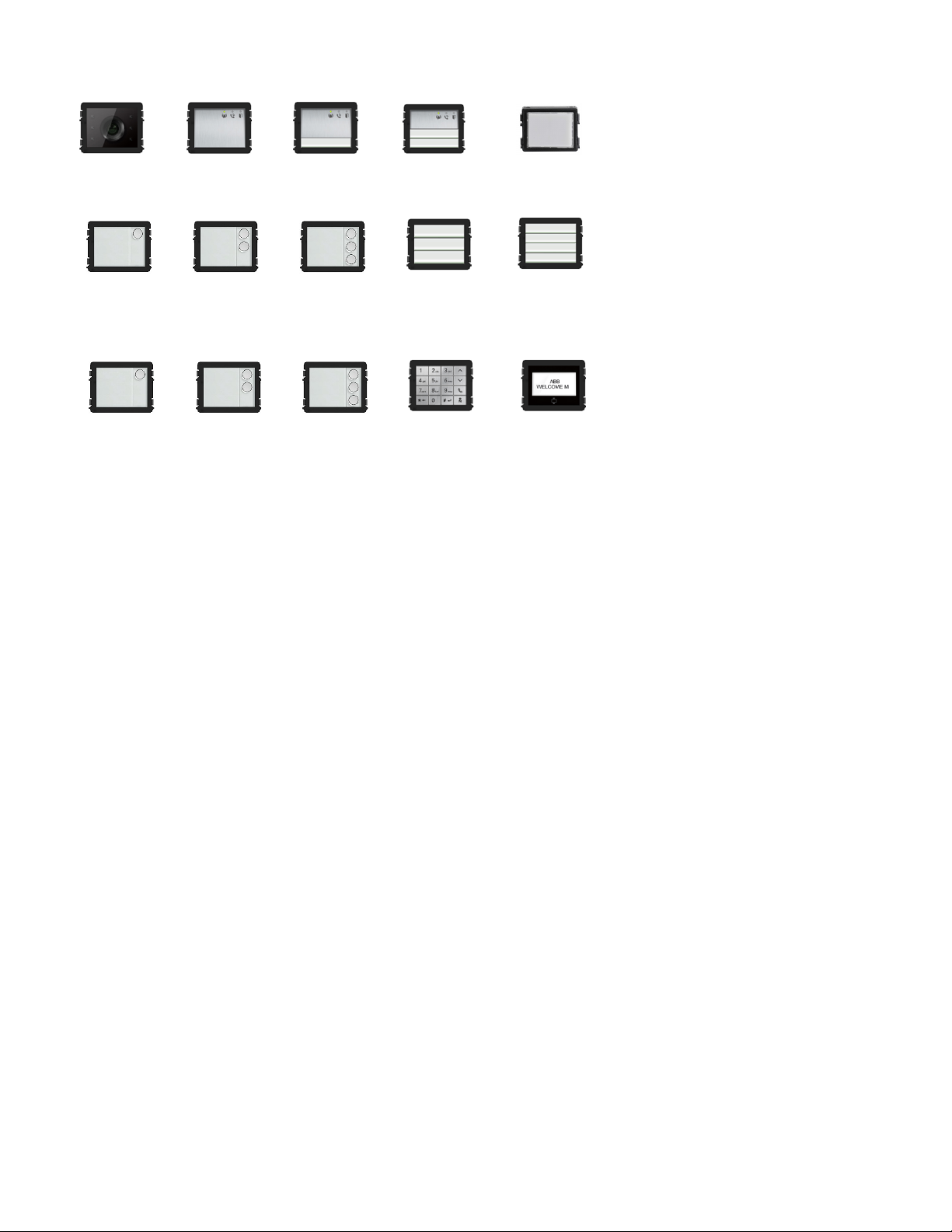
Camera module
Audio mod ule
Audio mod ule
Audio mod ule
Nameplate module
Round pushbutton
Round pushbutton
Round pushbutton
Pushbutto n
Pushbutto n
Round pushbutton
1 button, with NFC/IC
Round pushbutton
2 button, with
Round pushbutton
Keypad (3 versions)
Stainless steel
Aluminum
White
Display with ID
Display with IC
Module family
1 button
2 button
NFC/IC
3 button
3 button, with
NFC/IC
3/6 button
4/8 button

ABB Welcome
— 3 —
®
1 Safety....................................................................................................... 5
2 Intended use ............................................................................................ 5
3 Environment ............................................................................................. 5
3.1 ABB devices ............................................................................. 5
4 Terminal description ................................................................................. 6
4.1 Audio module ........................................................................... 6
4.1.1 Lock connected with terminals 3 and 4 .....................................12
4.2 Camera module .......................................................................13
4.2.1 Analog camera connected with terminal 1.................................14
4.2.2 Detached camera connection ...................................................15
4.3 Round pushbutton module .......................................................16
4.4 Pushbutton module ..................................................................18
4.5 Keypad module .......................................................................20
4.6 Display and card reader module ...............................................22
4.7 Nameplate module ..................................................................25
5 Operation ................................................................................................26
5.1 Pushbutton outdoor station ......................................................26
5.1.1 Addressing ..............................................................................26
5.1.2 Setting the language for the voice messages
(if the audio module has a speech synthesis function) ...............32
5.2 Pushbutton outdoor station with display module ........................34
5.3 Pushbutton outdoor station with keypad module .......................36
5.4 Round pushbutton outdoor station with IC/NFC ........................38
5.5 Keypad outdoor station ............................................................42
5.5.1 Call a resident (3 types) ...........................................................42
5.5.2 Call the guard unit ...................................................................44
5.5.3 If an indoor station is in “leave home mode” ..............................44
5.5.4 If a guard unit is in "intercept mode" .........................................45
5.5.5 System settings .......................................................................46
5.6 Keypad outdoor station without display
(camera + audio + keypad) ......................................................56
5.6.1 Calling a resident by inputting physical address ........................56
5.6.2 Call guard unit .........................................................................56
5.6.3 System settings .......................................................................56
6 Advanced configuration............................................................................58
7 Technical data .........................................................................................59
8 Mounting and installation .........................................................................60
8.1 Requirements for the electrician ...............................................60
8.2 General installation instructions ................................................61
8.3 Mounting .................................................................................62

ABB Welcome
— 4 —
®

ABB Welcome
— 5 —
Warning
Electric voltage!
Direct or indirect contact with live components can cause dangerous
currents to flow through the body, which may result in electric shock,
burns or even death.
- Always disconnect the main power supply prior to installation and/or
disassem bly.
- Work on the 110 V - 240 V supply system must be performed only
by qualified personnel.
Consider the protection of the environment!
Used electric and electronic devices must not be disposed of with
household waste.
– The device contains valuable raw materials that can be recycled
and should be disposed of at an appropriate recycling facility.
®
1 Safety
2 Intended use
The outdoor station is an integral part of the ABB Welcome door entry system and operates exclusively with components from this system.
The device must only be used with suitable ABB flush-mounted installation sockets and rain hood.
3 Environment
3.1 ABB devices
All packaging materials and devices from ABB bear the markings and test seals for proper disposal. Always dispose of the packing
materials, electric devices and their components via authorized collection facility or disposal company.
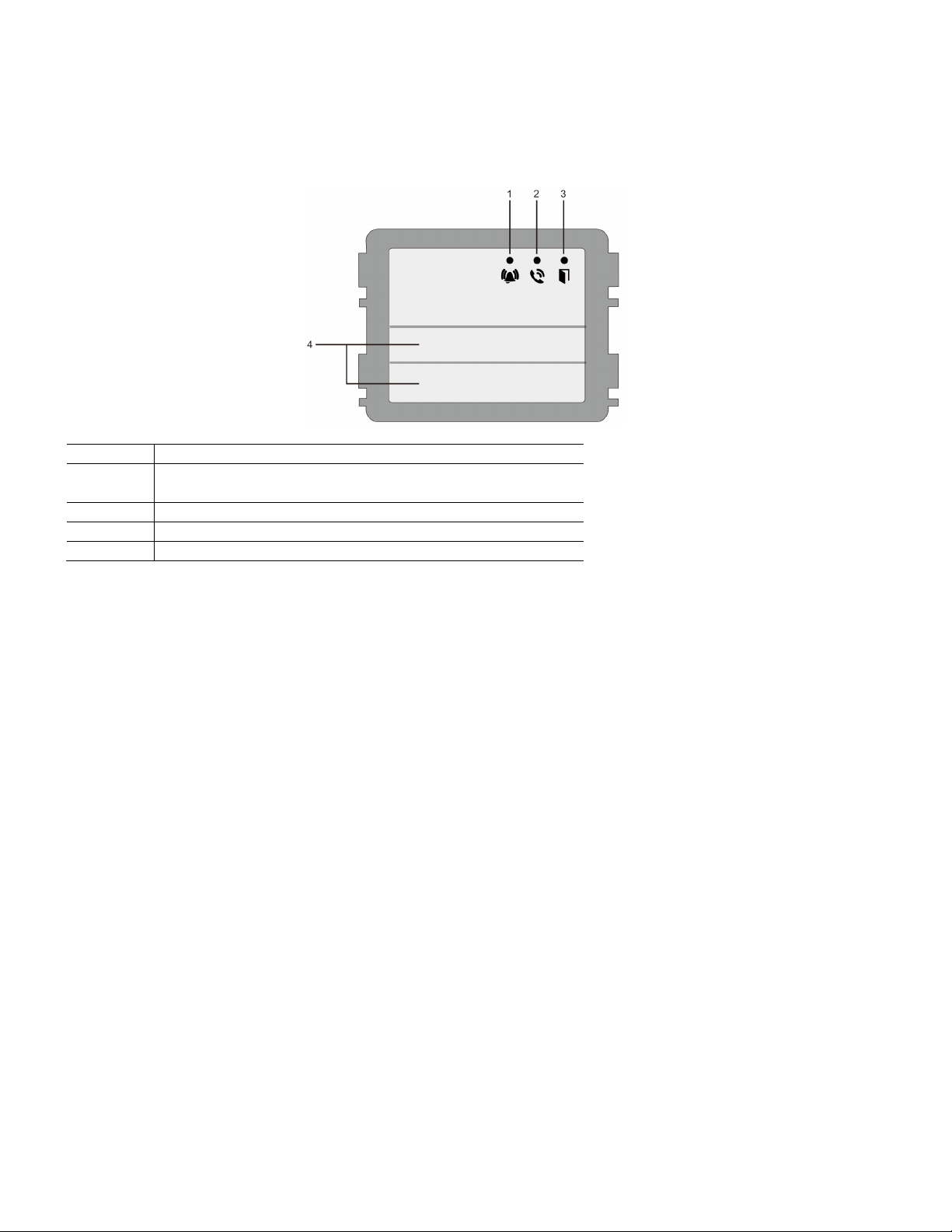
ABB Welcome
— 6 —
No.
Function
1
LED flashes slowly, indicating a call has been established
LED flashes fast, indicating that the system is busy
2
LED illuminates, indicating possible communication
3
LED illuminates, indicating the door is unlocked
4
Call pushbuttons
®
4 Terminal description
4.1 Audio module
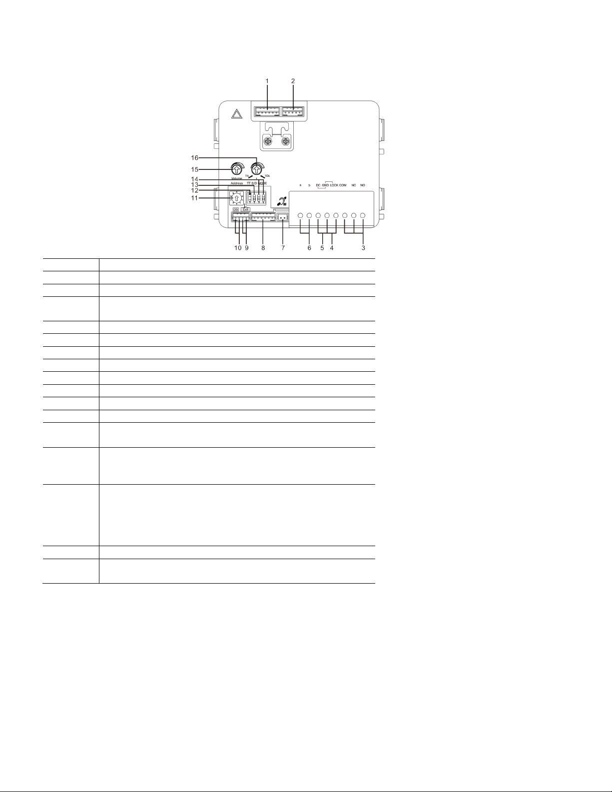
ABB Welcome
— 7 —
No.
Functions
1
Connector for camera module
2
Connector for device software update
3
Plug-in clamps (COM-NC-NO) for floating output, door opener (30 V
AC/DC, 1 A)
4
Plug-in clamps (Lock-GND) for door opener (18 V 4 A, 12 V 250 mA)
5
Plug-in clamps (DC-GND) for additional power supply
6
Plug-in clamps (a-b) for bus connection
7
Connector for induction loop module
8
Connector for next module
9
Connector for exit pushbutton
10
Connector for sensor for monitoring door status
11
Rotary switch for setting the address of OS (1-9)
12
Set feedback tones for pushbuttons and for outdoor station when making
a call: ON or OFF
13
Configure pushbuttons in a single column or double column mode
(ON=double column; OFF=single column)
This only affects the bar pushbutton, not the round pushbutton.
14
Configure functions of the first and second pushbuttons
3->OFF, 4->OFF=call indoor station and call indoor station
3->ON, 4->OFF=switch on lighting and call indoor station
3->OFF, 4->ON=call guard unit and call indoor station
3->ON, 4->ON=switch on lighting and call guard unit
15
Adjust the loudspeaker volume
16
*Adjust the door lock release time, 1-10 s eco nds (available for the
lock connected with the default lock)
®
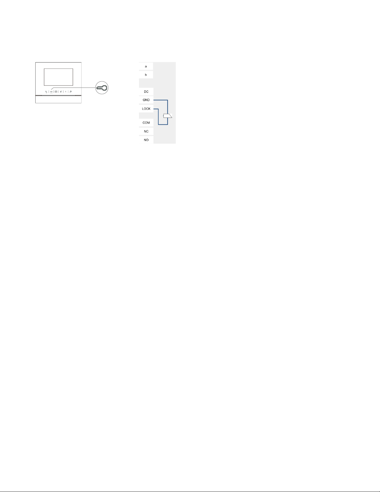
ABB Welcome
— 8 —
®
*Default lock (first lock): Released by “unlock” button of the indoor station. Factory setting
is LOCK-GND.
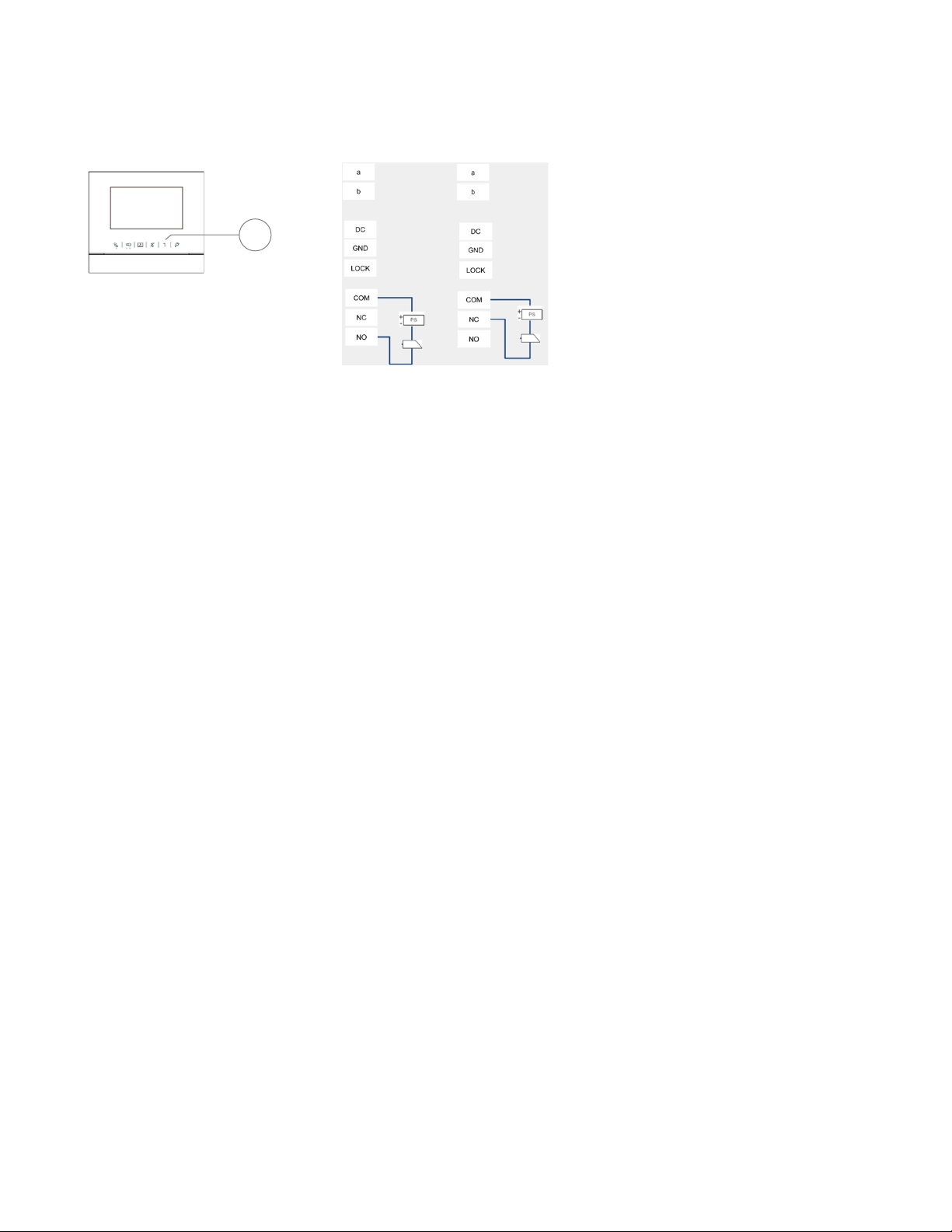
ABB Welcome
— 9 —
1
®
Second lock: Rel eased by programmable button “1” of the indoor station. Factory setting
is COM-NC-NO.
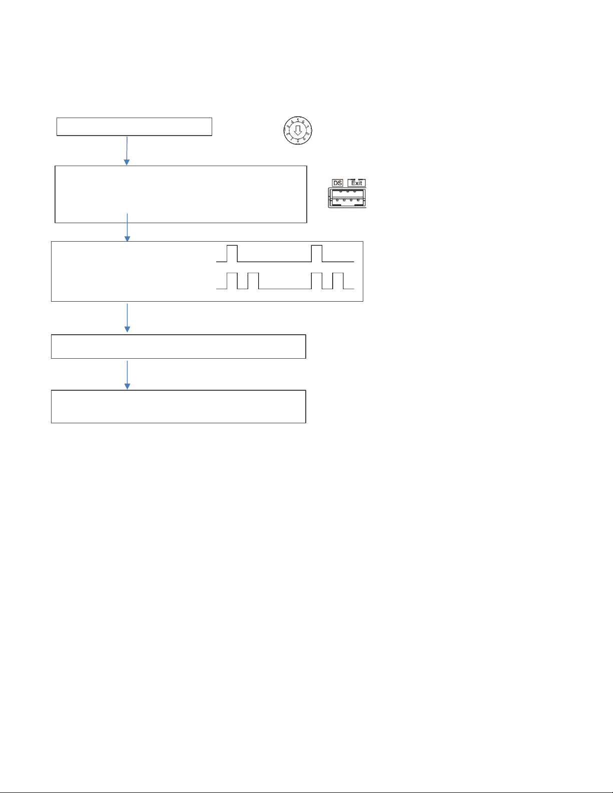
ABB Welcome
— 10 —
Set outdoor station address ="0"
Short circuit the "Exit" two terminals for 3 seconds to enter the
Tones for indication:
Short circuit “Exit” terminal on outdoor station to switch the default lock
30 seconds time available to save the setting and exit the
®
Change default lock
Default lock can be set at either "Lock-GND" or "NO-NC-COM"
1
setting mode
(3 LED flashes green to show the setting mode for aluminum outdoor
station)
(prompt tone “di” for stainless outdo or station)
Lock 1 (LOCK-GND) = default lock
Lock 2 (NC-NO-COM) = default lock
programming mode
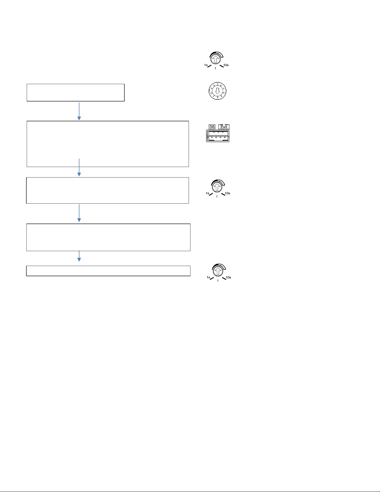
ABB Welcome
— 11 —
Set the lock time of the default lock
Set the lock time of the second lock
Set outdoor station address ="0"
Short circuit the “DS” two terminals for 3 seconds to enter the
Record the time for first lock
30 seconds time available to save the setting and exit the
At last set the time back for 1st-Lock
Reset the time to the original time for first lock
®
Set the time by the potentiometer, from 1-10 seconds
setting mode
(3 LED flashes green to show the setting mode for aluminu m outdoor
station)
(Beep tone sounds for stainless outdoor station)
Then set the time for second-Lock from 1-10 seconds
programming mode
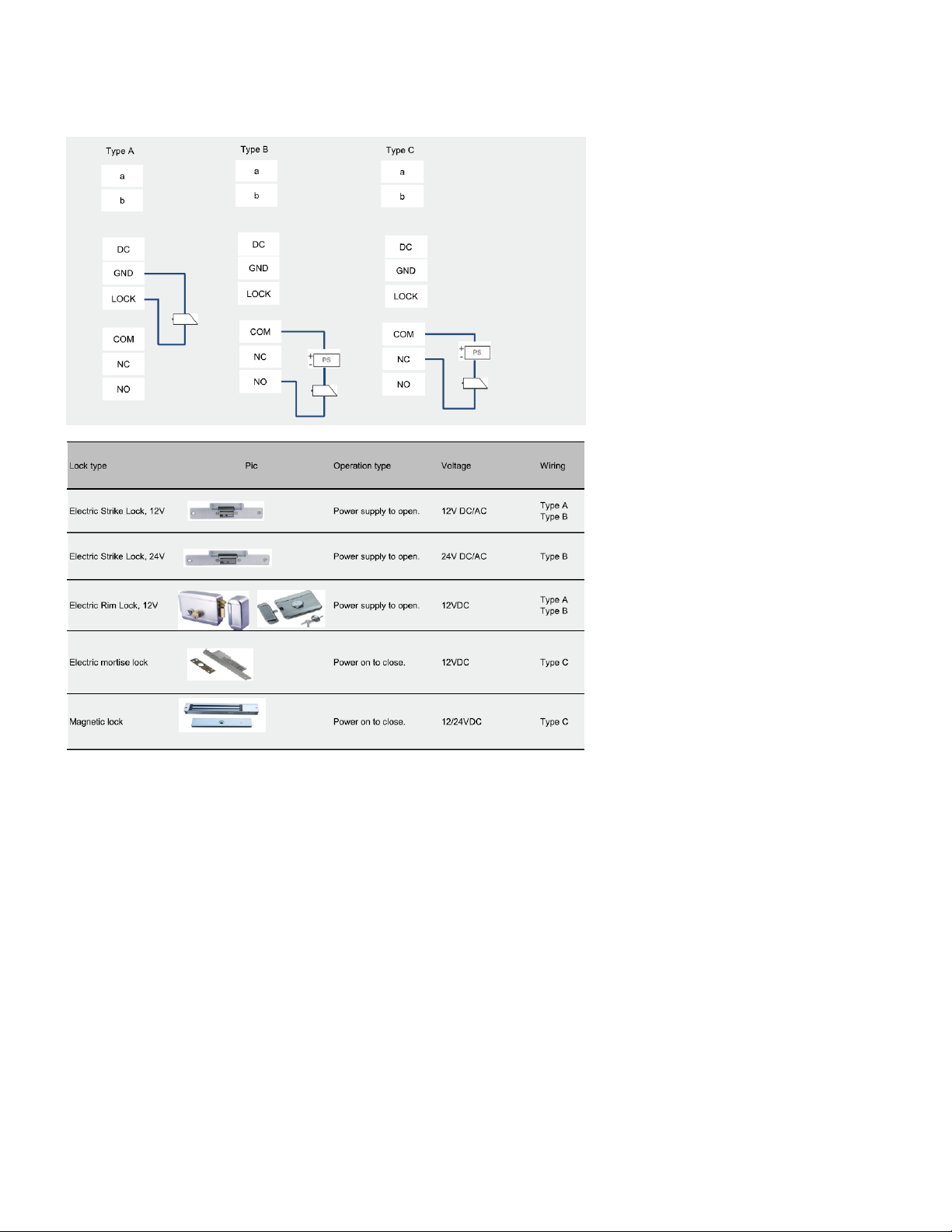
ABB Welcome
— 12 —
®
4.1.1 Lock connected with terminals 3 and 4
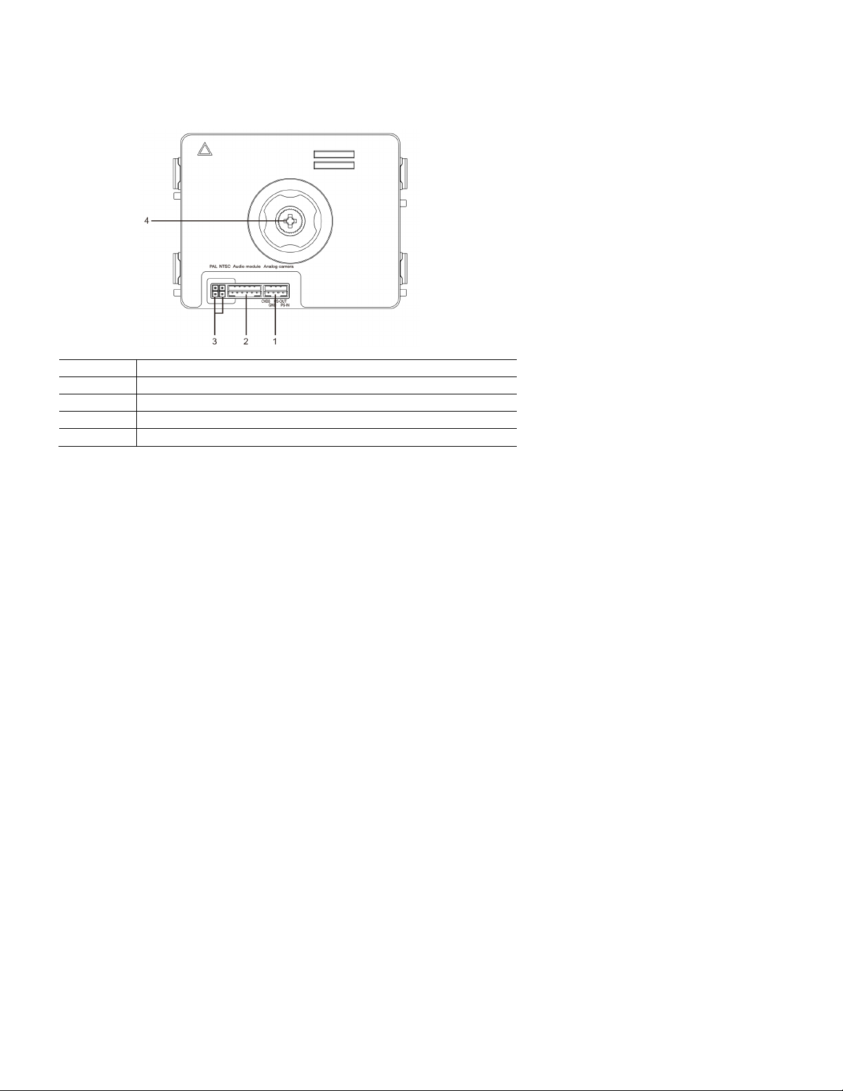
ABB Welcome
— 13 —
No.
Functions
1
Connector for additional analog camera
2
Connector for audio module
3
Jumper for setting the video format: PAL or NTSC
4
Adjust the camera view area
®
4.2 Camera module
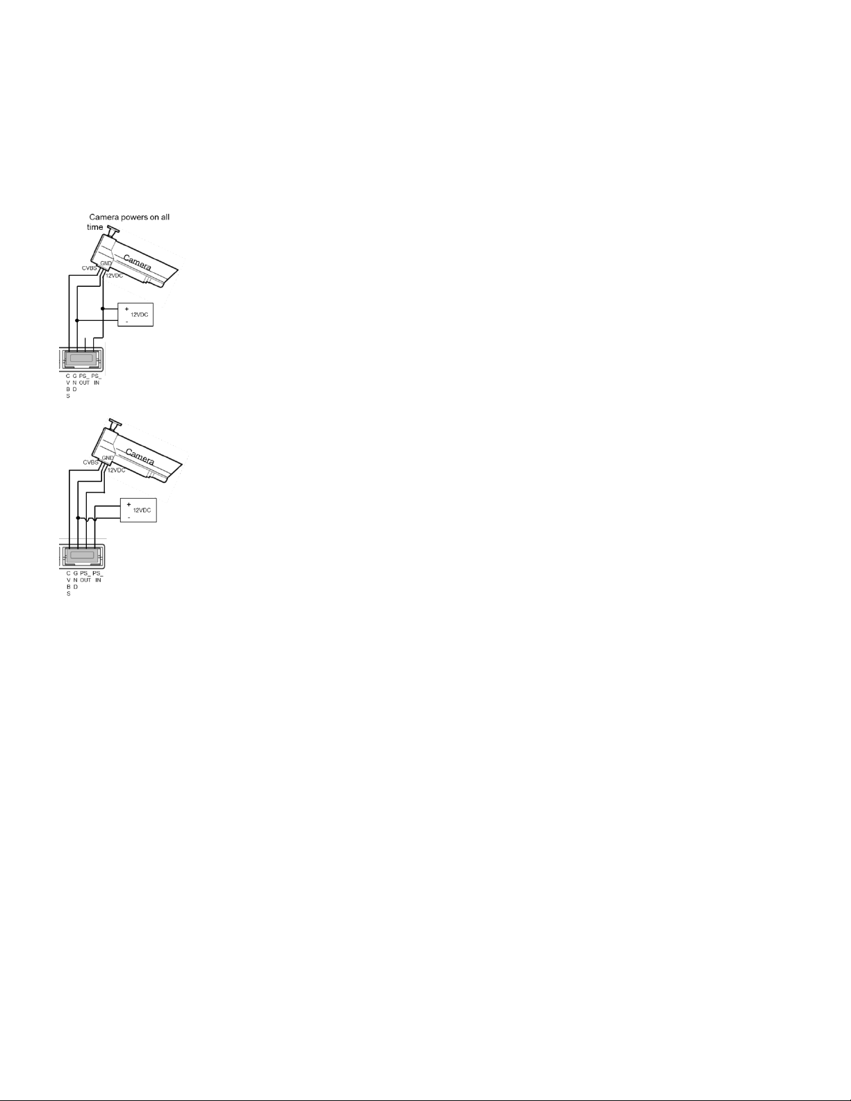
ABB Welcome
— 14 —
®
4.2.1 Analog camera connected with terminal 1
All the cameras with the video output of 1Vp-p 75Ω, CVBS (composit e video broadcast signal) can be connected with the camera m odule.
Generally, the transmission distance from the analog camera to the outdoor station can reach up to 164 ft. by coax cables or about 33 ft. by other
types of cables.
Two types of connections:
Option 1: The analog camera is powered on all the time.
Option 2: The analog camera is powered on only during working hours.
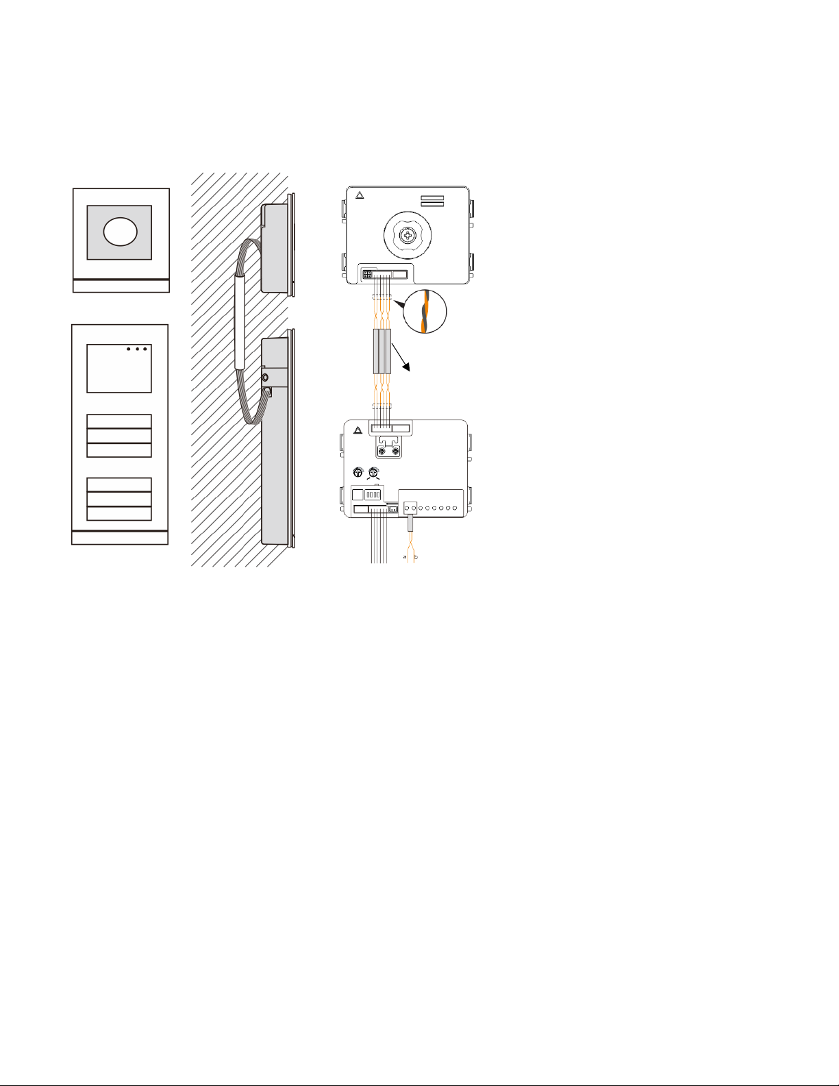
ABB Welcome
— 15 —
3 pairs 2-wire bus
together
Max:10 metres
®
4.2.2 Detached camera connection
Camera module can be used as a detached camera. Wiring is shown below.
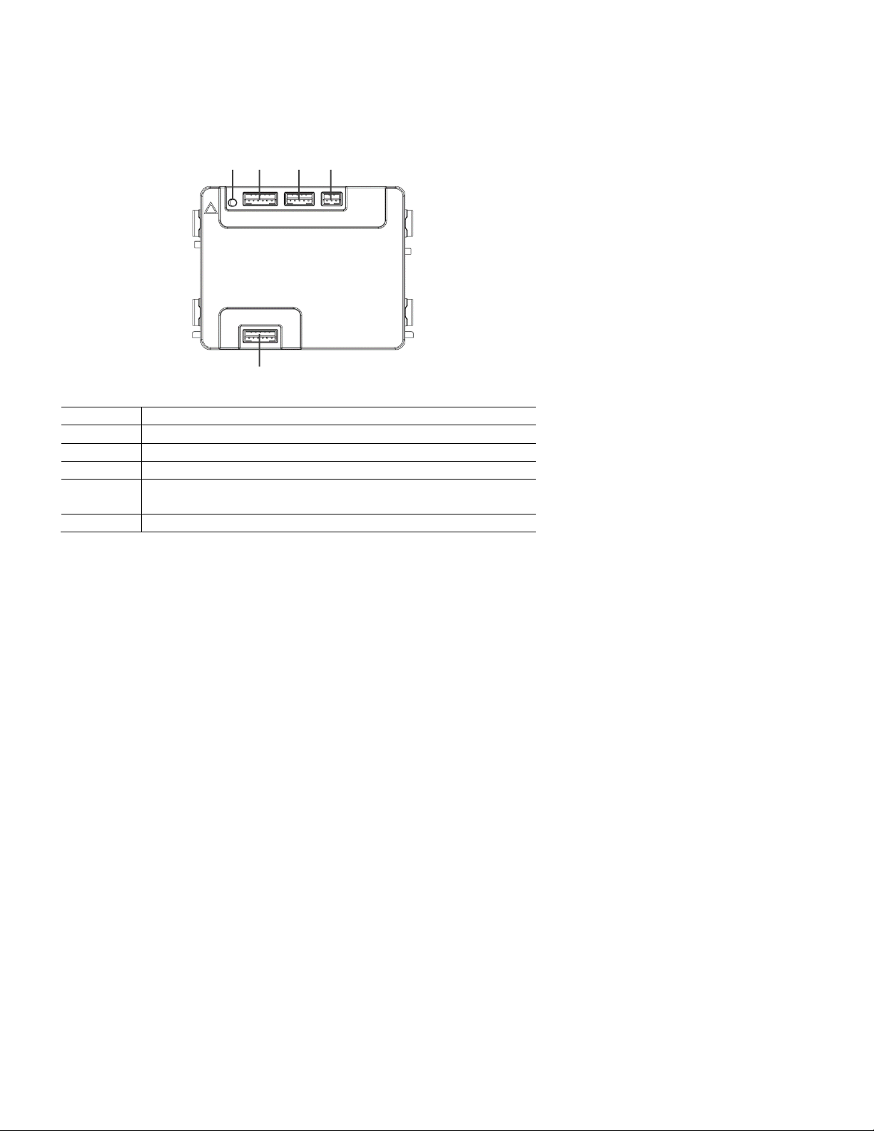
ABB Welcome
— 16 —
No.
Functions
1
Program button
2
Connector for previous module
3
Connector for device software update
4
Connector for Wiegand output
Default format is 26 bits; it can also be extended to 34 bits.
5
Connector for next module
1
2 3 4
5
®
4.3 Round pushbutton module
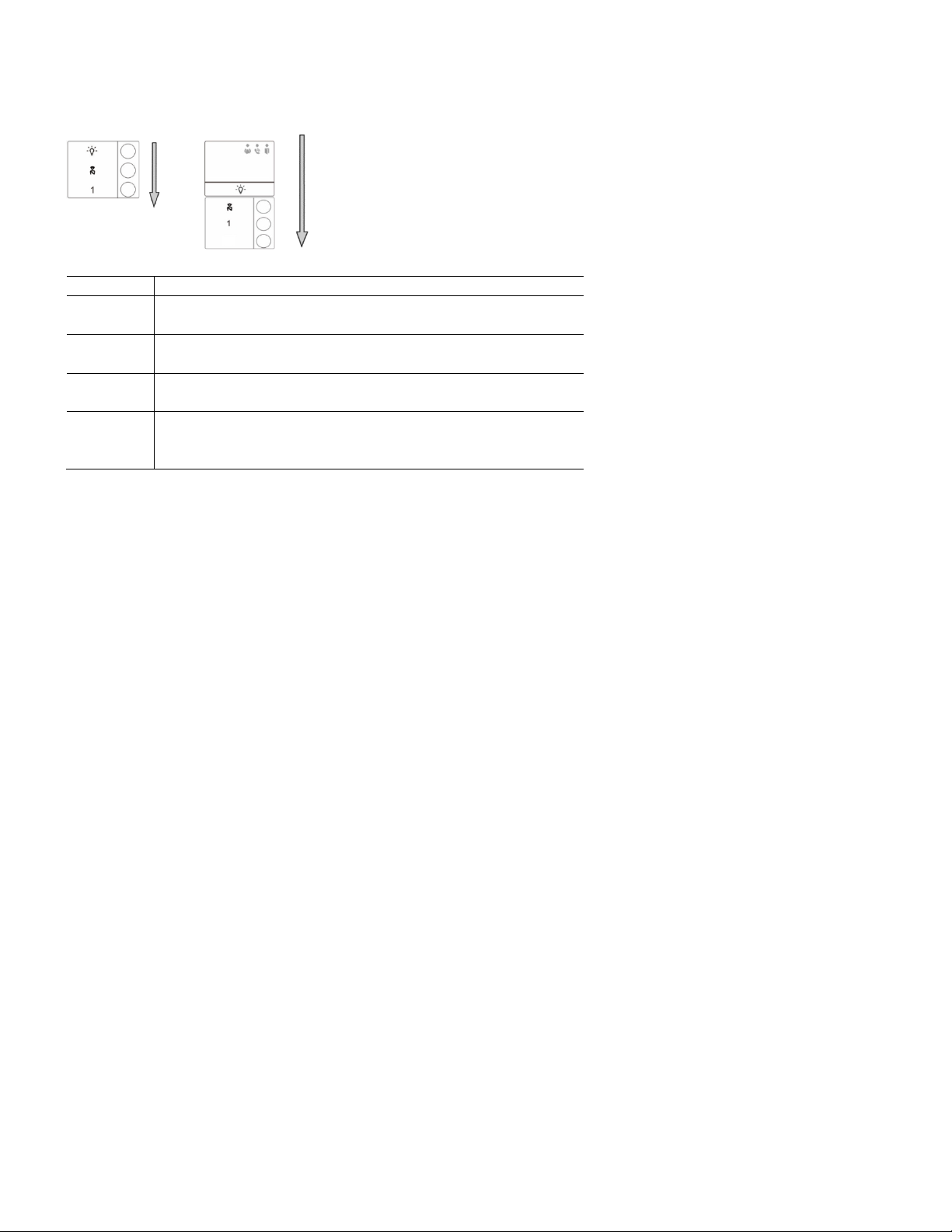
ABB Welcome
— 17 —
No.
Functions
1
Regardless of the structure of the pushbutton module, button numbers are
listed from top to bottom.
2
Lighting switch and call guard unit function is always assigned to the first
and second button, which is set by audio module.
3
User names can be printed by us ing the labeling tool of the ABB Welcome
configuration software.
4
The round pushbutton module with NFC/IC card reader supports the
NFC/IC c ard. A mobile phone with NFC function is acceptable. (“Door
Open” App required.)
2
®
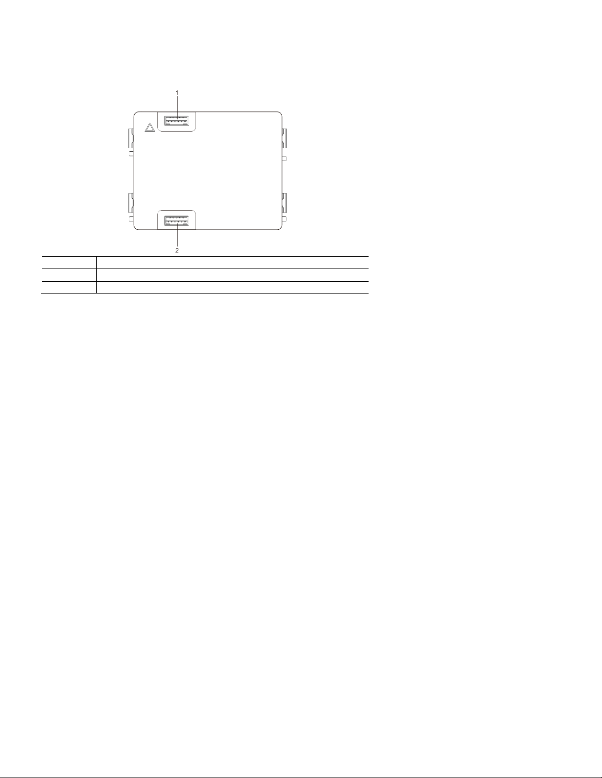
ABB Welcome
— 18 —
No.
Functions
1
Connector for previous module
2
Connector for next module
®
4.4 Pushbutton module
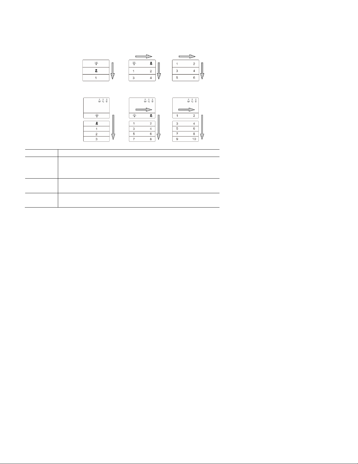
ABB Welcome
— 19 —
No.
Functions
1
Regardless of the structure of the pushbutton module, the button numbers
are listed from top to bottom and from left to right (in the double column
mode).
2
Lighting switch and call guard unit function is always assigned to the first
and second button.
3
User names can be printed by the using the labeling tool of the ABB
Welcome configuration software.
®
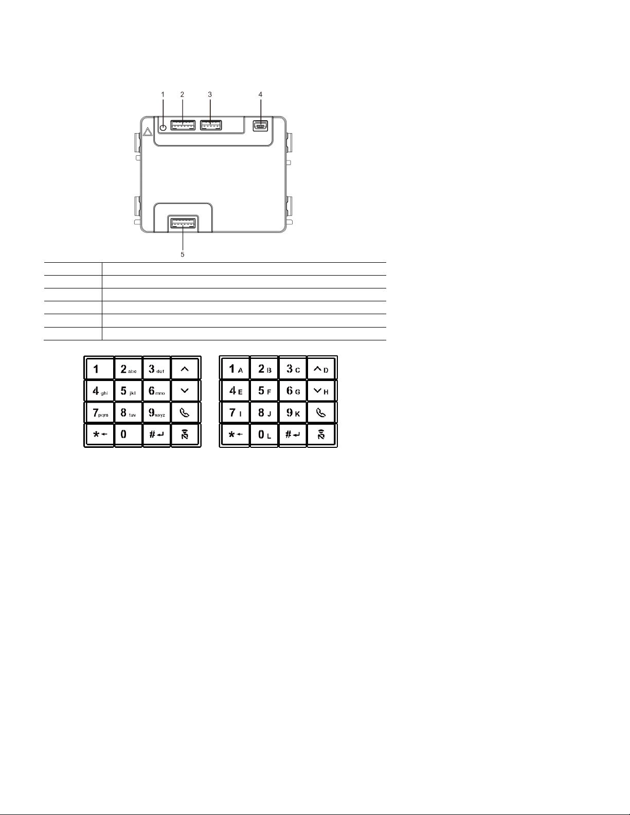
ABB Welcome
— 20 —
No.
Functions
1
Program button
2
Connector for previous module
3
Connector for device software update
4
USB connector for connection to a PC: Download/upload the configuration.
5
Connector for next module
®
4.5 Keypad module
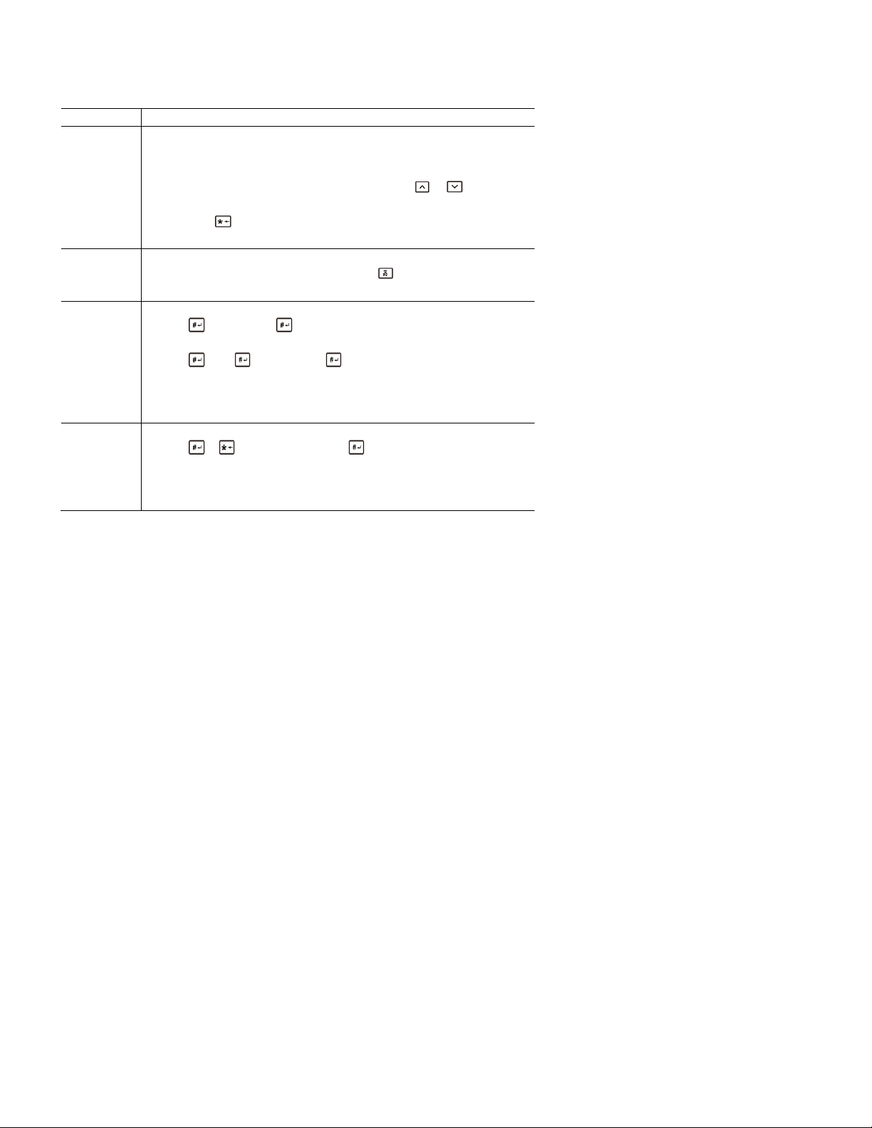
ABB Welcome
— 21 —
No.
Functions
1
Call resident
A visitor inputs an indoor station number (001) or apartment number (e.g. ,
0101, programmed in advance) to call a resident.
*Also, the visitor can select a resident name with the or buttons of
the accompanying display module to make a call.
Pressing the button will cancel the call.
*This function is only available in Fig. 1.
2
Calling the guard unit
A visitor can call a guard unit by pressing the button if the guard unit is
available in the system.
3
Unlocking by password
Press " + password+ “ to release the default lock to the audio
module.
Press " +2 + + password + " to release the 2nd lock connected
to the audio module.
The initial password is 123456. Residents can set their own customized
password with indoor stations.
4
System engineering configuration
Press " + + system password + " to enter the system
engineering configuration menu.
The initial system password is 345678, and it can be modified by the
administrator.
®
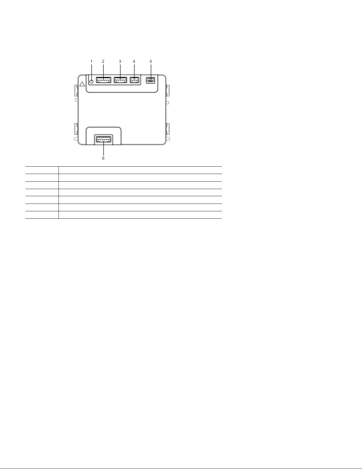
ABB Welcome
— 22 —
No.
Functions
1
Program button
2
Connector for previous module
3
Connector for device software update
4
Connector for Wiegand output
5
USB connector for connecting to a PC: Download/upload the configuration.
6
Connector for the next module
®
4.6 Display and card reader module
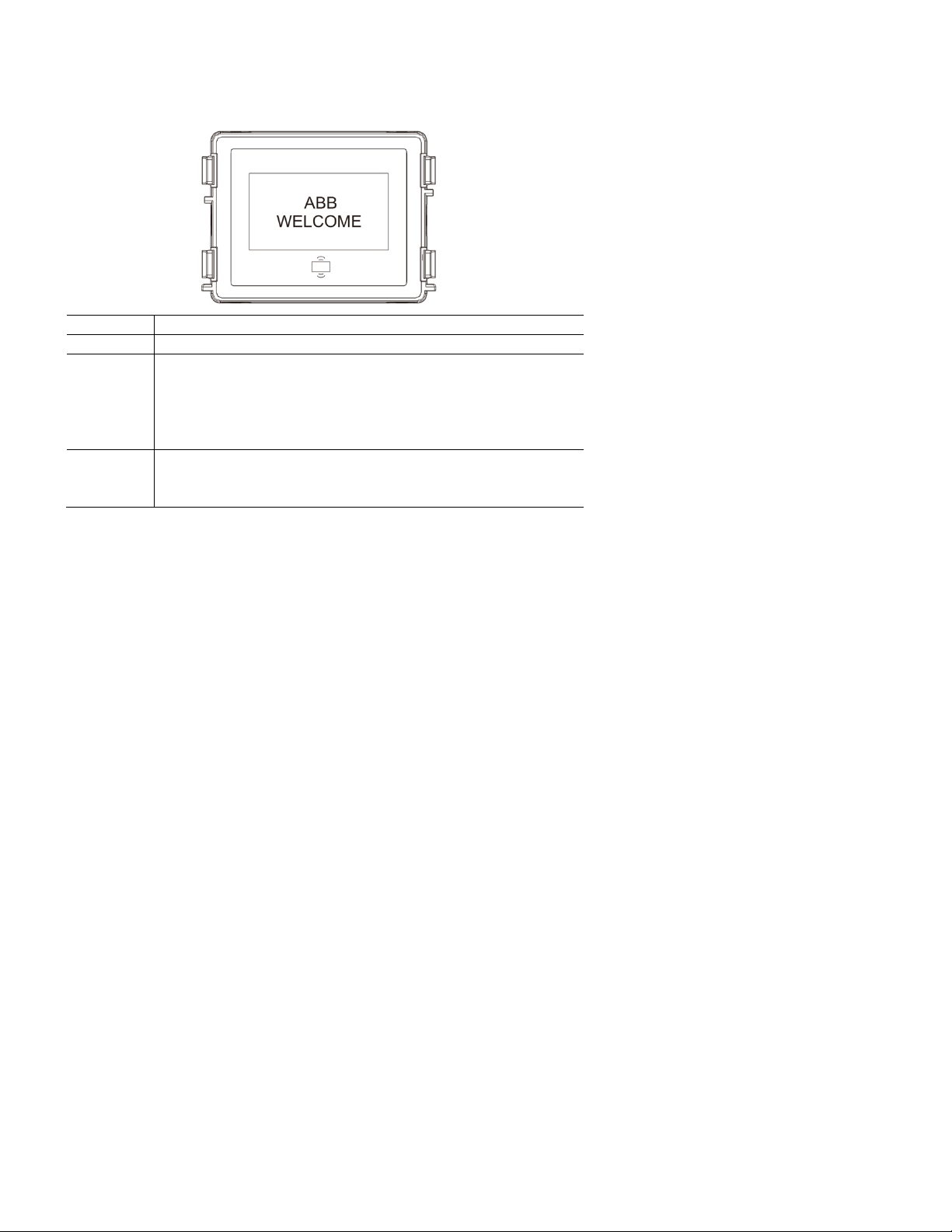
ABB Welcome
— 23 —
No.
Functions
1
LCD display
2
Support ID or IC card.
Swipe the registered card to release the door lock. The card can be
programmed through the module itself, or by using a PC to download the
program file. (M251021CR is accompanied by an ID card reader, while
the M251022CR is accompanied by an IC card reader.)
3
Support Wiegand output.
The default Wiegand format is 26 bits, but it can also be extended
to 34 bits.
®
*The display module must be connected after the audio module.
 Loading...