

Latch key safety limit switches
1 2 3 5 10
Current (A)
0.1
0.2
0.3
0.5
1
2
3
5
Millions of operating cycles
12 - 24
48
130
230
Technical data
General Data
Standards IEC 60947-1, IEC 60947-5-1, EN 60947-1, EN 60947-5-1, UL 508,
and CSA C22-2 No. 14
Certications - Approvals UL and CSA
Air temperature near the device
– during operation °C -25 ... +70
– for storage °C -30 ... +80
Climatic withstand According to IEC 68-2-3 and salty mist according to IEC 68-2-11
Mounting positions All positions are authorised
Shock withstand (according to IEC 68-2-27 and EN 60068-2-27) g Limit switch with small latch (key): 10 g
(1/2 sinusoidal shock for 11 ms) no change in Limit switch with rotative axis or lever: 40 g
contact position
Resistance to vibrations g 5 g (10 ... 500 Hz) no change in position of contacts > 100 μs
Protection against electrical shocks (acc. to IEC 536) Class II
Degree of protection (according to IEC 529 and EN 60529) UL Type 4 & IP65
Minimum actuation speed m/s Slow action contacts 0.060 / Snap action contacts 0.001
limit switches
Safety
Electrical Data
Rated insulation voltage U
– according to IEC 60947-1 and EN 60947-1 V 690 (degree of pollution 3)
– according to UL 508, CSA C22-2 No. 14 A600, Q600
Rated impulse withstand voltage U
(according to IEC 60947-1 and EN 60947-1)
Conventional free air thermal current I
(according to IEC 60947-5-1 and EN 60947-5-1) (0 < 40 °C)
Short-circuit protection - gG type fuses A 10
Rated operational current
/ AC-15 – acc. to IEC 60947-5-1 24 V - 50/60 Hz A 10
I
e
130 V - 50/60 Hz A 5.5
230 V - 50/60 Hz A 3.1
240 V - 50/60 Hz A 3
400 V - 50/60 Hz A 1.8
– according to UL 508, CSA C22 No.14 A600
Ie / DC-13 – acc. to IEC 60947-5-1 24 V - d.c. A 2.8
110 V - d.c. A 0.6
250 V - d.c. A 0.27
– according to UL 508, CSA C22 No.14 Q600
Positivity Contacts with positive opening operation as per IEC 60947-5-1 chapter 3
and EN 60947-5-1
Resistance between contacts mΩ 25
Mechanical durability Millions of operations > 1 million of operating cycles
Max. switching frequency Cycles/h 600
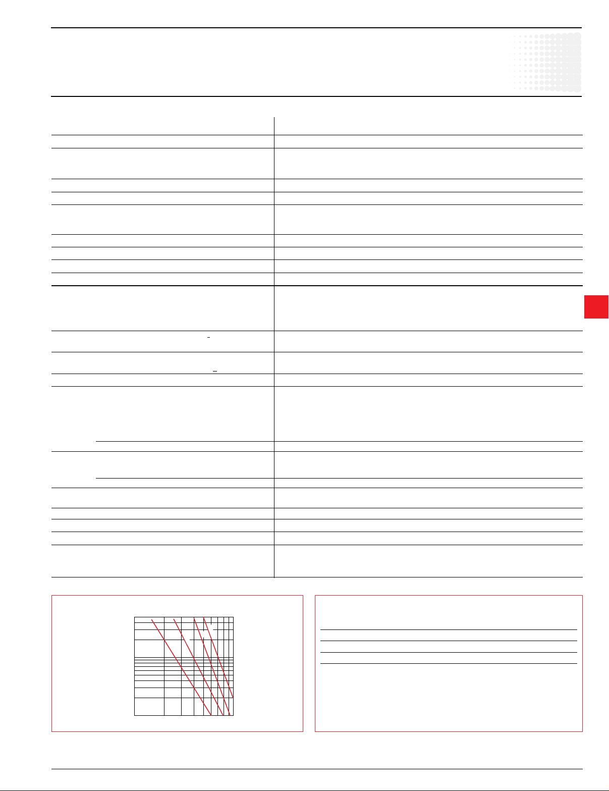
Electrical durability (according to IEC 60947-5-1 appendice C) Utilization categories AC-15 and DC-13 (see curves and values below)
– Max. switching frequency Cycles/h 3600
– Load factor 0.5
ElectricaldurabilityforAC-15utilizationcategory ElectricaldurabilityforDC-13utilizationcategory
Slow action Slow action
Power breaking for a durability of
5 million operating cycles
Voltage 24 V 12 W
Voltage 48 V 9 W
Voltage 110 V 6 W
i
kV 6
imp
A 10
th
9
Low Voltage Products & Systems 9.91
ABB Inc. • 888-385-1221 • www.abb.us/lowvoltage 1SXU000023C0202
Latch key safety limit switches
90˚
180˚
270˚
0˚
0˚...360˚
= =
Front translation
movement
Vertical translation
movement
Clearance = 2 to 3 mm
Gasket 1.6 mm thick
included
Vertical translation
movement
Clearance = 2 to 4 mm
Gasket 1.6 mm thick included
Front transition movement
Safety
limit switches
Implementation
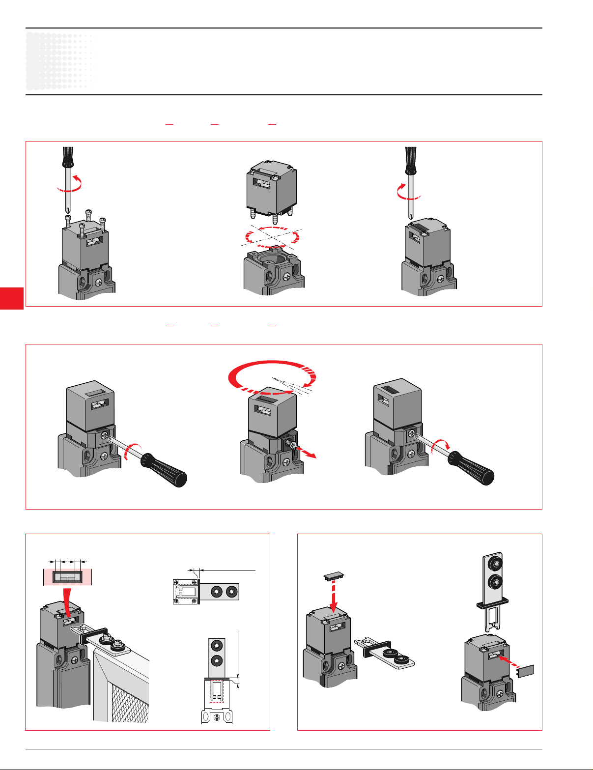
Limit switches with small latch (key) LS30P80...-S,LS31P80...-SandLS35P80...-S
• Head adjustment every 90°.
9
Limit switches with small latch (key) LS30P81...-S,LS31P81...-SandLS35P81...-S
• Pivoting head continuous between 0° to 360°.
Technical data
Adjusting the small latches (keys) Blanking off the window not used (NEMA 4x protection)
Clearances to be respected on installation
9.92 Low Voltage Products & Systems
1SXU000023C0202 ABB Inc. • 888-385-1221 • www.abb.us/lowvoltage
Safety
90˚
180˚
270˚
0˚
90˚
180˚
270˚
0˚
90˚
180˚
270˚
0˚
Heads P75 and P76
Head P81 Head P77
Head P80
A
F
B
C
C
D
E
C
limit switches
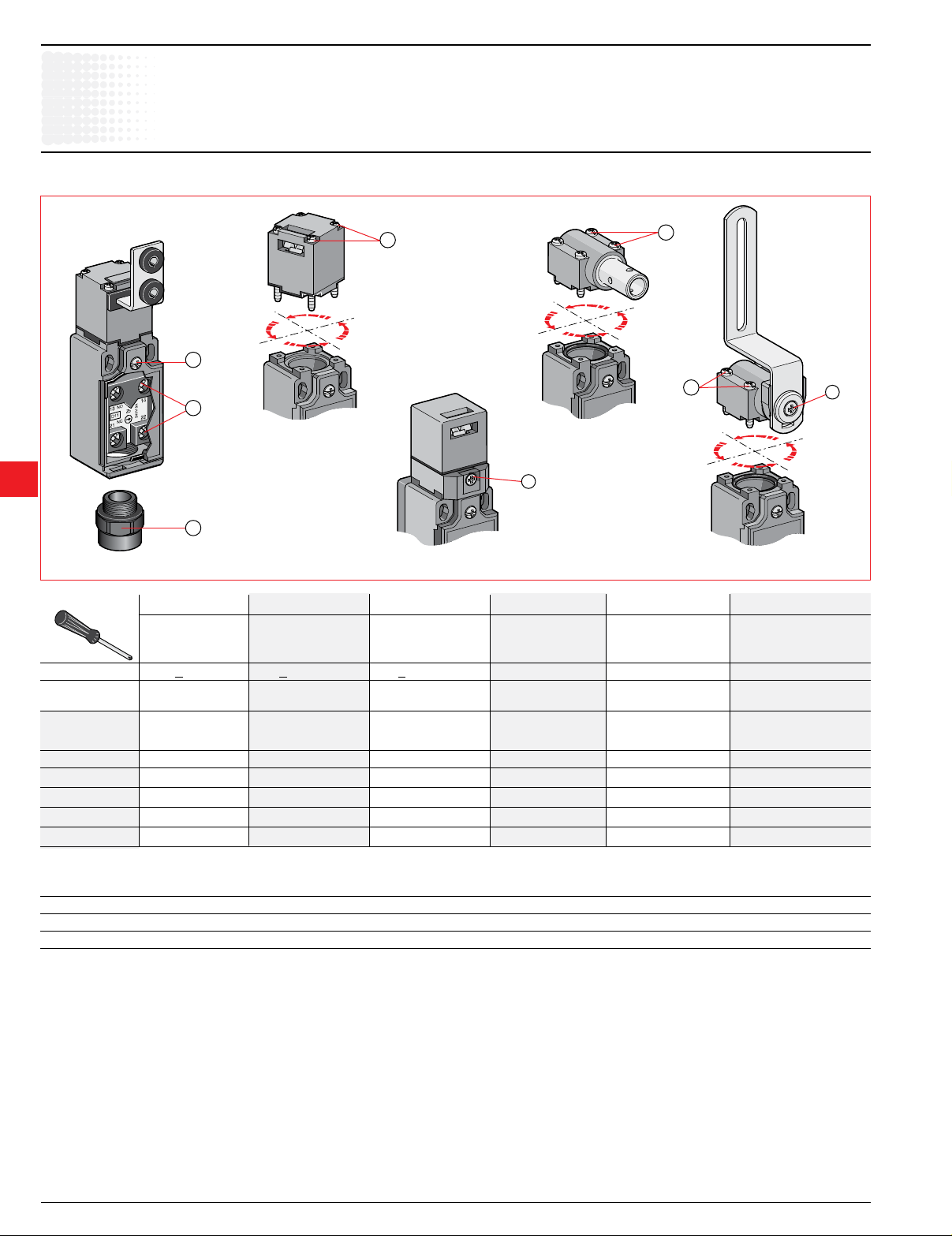
Tightening torques
9
Rotative axis safety limit switches
Technical data
A B C D E F
Contact block Closing Assembling Assembling Adjusting Cable
connecting the cover the operating the ush mounting the pivoting inlet by
terminals head right angle lever head 1/2" NPT adaptor
Screws
Tightening Recommended Max. Recommended Max. Recommended Max. Recommended Max. Recommended Max. Recommended Max.
torque N.m / lb.in N.m N.m / lb.in N.m N.m / lb.in N.m N.m / lb.in N.m N.m / lb.in N.m N.m / lb.in N.m
Limit
switches
M3.5 + pozidriv 2 ø3 + pozidriv 1 ø3 + pozidriv 1 M3.5 pozidriv 2 M3 Philips No. 1 –
LS35P80...-S 0.8 / 7 0.9 0.5 / 4.3 0.8 0.5 / 4.3 0.8 – – – – 17 / 150 18
LS35P81...-S 0.8 / 7 0.9 0.5 / 4.3 0.8 – – – – 0.3 / 2.63 0.5 17 / 150 18
LS35P75...-S 0.8 / 7 0.9 0.5 / 4.3 0.8 0.5 / 4.3 0.8 – – – – 17 / 150 18
LS35P76...-S 0.8 / 7 0.9 0.5 / 4.3 0.8 0.5 / 4.3 0.8 – – – – 17 / 150 18
LS35P77...-S 0.8 / 7 0.9 0.5 / 4.3 0.8 0.5 / 4.3 0.8 0.5 / 4.3 0.8 – – 17 / 150 18
Connecting data of contact blocks
Connecting terminals M3.5 (+,–) pozidriv 2 screw with cable clamp
Connecting capacity 1 or 2 x mm
2
/ AWG 0.5 mm2 / AWG 20 to 2.5 mm2 / AWG 14
Terminal marking According to EN 50013
9.94 Low Voltage Products & Systems
1SXU000023C0202 ABB Inc. • 888-385-1221 • www.abb.us/lowvoltage

Safety Limit Switches
L0538D
0
C C
C1
C2
F1
CP
P
O
P
A
P
P
L
C
L
L0539D
C C
0
C C
5.00
11-12
21-22
21.5 mm
3.5
31° 31°6° 6°
0°
21-22
13-14
90° 90°
15° 15°
21-22
13-14
C
C
C C
0
C
L0537D
L0544D
C
1-1
C
1-2
C
P
C
L
P
P
Key extraction
21-22
13-14
Key insertion
C
1-1
C
1-2
C
P
C
L
P
P
21-22
13-14
21-22
13-14
0
Actuation
and
Release
21-22
21-22
Contact closed
Contact open
Contacts identication (example)
Travel and Operating diagrams
Key
extraction
C: travel in millimetres C: travel in degrees C: travel in degrees
PO Free position:
position of the switch actuator when no
external force is exerted on it.
PA Operating position:
position of the switch actuator, under the
effect of force F1, when the contacts leave
their initial free position.
PP Positive opening position:
position of the switch actuator from which
positive opening is ensured.
L Max. travel position:
maximum acceptable travel position of the
switch actuator under the effect of a force
F1.
Note: C
C
= pre-travel of contact 21-22,
1-1
= pre-travel of contact 13-14.
1-2
C1 Pre-travel (average travel):
distance between the free position PO and
the operating position PA.
CP Positive opening travel:
minimum travel of the switch actuator, from
the free position, to ensure positive opening
operation of the normally closed contact
(N.C.).
C2 Over-travel (average travel):
distance between the operating position PA
and the max. travel position L.
CL Max. travel (maximum travel):
distance between the free position PO and
the max. travel position L.
Examples:
LS35P80L02-S LS35P76D11-S
Simultaneous slow action contacts non-overlapping slow action contacts
Diagram for non-overlapping slow
action contacts:
C: travel
Diagram for non-overlapping slow
action contacts:
Diagram Diagram
in millimetres / key travel in degrees / lever rotation
48
AC1300
C: travel
Contacts position

Safety
Stop
Gap
Stop
Gap
To foresee a mechanical stop unit
and a function gap
Gap: Setting of small latches (key),
page 9.75
R...
The small latch (key) shall be presented in the axis of the control head.
Correct
Wrong
Curve of connecting cable Cable gland orientation
Wrong
limit switches
9
Rotative axis safety limit switches
Technical data
Utilization cautions
9.96 Low Voltage Products & Systems
1SXU000023C0202 ABB Inc. • 888-385-1221 • www.abb.us/lowvoltage

Safety
limit switches
Safety limit switches
Technical data
Specications, directives, standards & EC conformity
Definitions
The ABB limit switches listed in this catalogue are developed and manufactured according to the rules set out in IEC international publications and EN European standards. In
most countries, the devices are not subject to further obligation for approval. In some
countries, however, the law stipulates obligation for approval.
Specifications
• InternationalSpecications
The International Electrotechnical Commission, IEC, which is part of the International
Standards Organization, ISO, publishes IEC publications which act as a basis for the
world market.
• EuropeanSpecications
The European Committee for Electrotechnical Standardization (CENELEC), grouping
18 European countries, publishes EN standards for low voltage industrial apparatus.
These European standards vary very little from IEC international standards and use
a similar numbering system. The same is true of national standards. Contradicting
national standards are withdrawn.
• HarmonizedEuropeanSpecications
The European Committees for Standardization (CEN and CENELEC), grouping 18
European countries, publish EN standards relating to safety of machinery.
• SpecicationsinCanadaandtheUSA
These are equivalent, but differ markedly from IEC, UTE, VDE and BS specications.
UL Underwriters Laboratories (USA)
CSA Canadian Standards Association (Canada)
Remark concerning the label issued by the UL (USA). Two levels of acceptance be-
9
tween devices must be distinguished:
"Recognized" Authorized to be included in equipment, if the equipment in
They bear the mark:
"Listed" Authorized to be included in equipment and for separate sale
They bear the mark:
European directives
The guarantee of free movement of goods within the European Community assumes
elimination of any regulatory differences between the member states. European
Directives set up common rules that are included in the legislation of each state while
contradictory regulations are cancelled.
There are three main directives:
• LowVoltageDirective73/23/EEC, amended by Directive 93/68/EEC concerning
electrical equipment from 50 to 1000 V a.c. and from 75 to
1500 VDC. This species that compliance with the requirements that it sets out is
acquired once the equipment conforms to the standards harmonized at European
level: EN 60947-1 and EN 60947-5-1 for limit switches.
• MachinesDirectives-89/392/EEC,91/368/EEC,93/44/EEC,93/68/EEC - dening main safety and health requirements concerning design and manufacture of the
machines and other equipment including safety components in European Union
countries.
• ElectromagneticCompatibilityDirective89/336/EEC, amended by Directive
92/31/EEC and Directive 93/68/EEC concerning all electrical devices likely to create
electromagnetic disturbances.
Signification of CE marking:
CE marking must not be confused with a quality label.
CE marking placed on a product is proof of conformity with the European Directives
concerning the product.
CE marking is part of an administrative procedure and guarantees free movement of
the product within the European Community.
Standards
• Internationalstandards
IEC 60947-1 Low-voltage switchgear and controlgear – Part 1: General
IEC 60947-5-1 Low-voltage switchgear and controlgear – Part 5: Control
IEC 60204-1 Electrical equipment of industrial machines – Part 1: General
IEC 60204-2 Electrical equipment of industrial machines – Part 2: Item
question has been entirely mounted and wired by qualied
personnel. They are not valid for use as "General purpose
products" as their possibilities are limited.
as "General purpose products" components in the USA.
Rules (NFC 63-001).
circuit devices and switching elements – Section 1: Electromechanical control circuit devices (NFC 63-146) – Chapter 3:
Special requirements for control switches with positive opening
operation.
requirements (≈ NFC 79-130).
designation and examples of drawings, diagrams, tables and
instructions (Appendices D and E of Publications
IEC 60204-1).
.
.
• EuropeanStandards
EN 50005 Low-voltage switchgear and controlgear for industrial use – Termi-
EN 50013 Low-voltage switchgear and controlgear for industrial use –
EN 50041 Low-voltage switchgear and controlgear for industrial use –
EN 50047 Low-voltage switchgear and controlgear for industrial use –
EN 60947-1 Low-voltage switchgear and controlgear for industrial use –
EN 60947-5-1 Low-voltage switchgear and controlgear for industrial use – Part
• HarmonizedEuropeanStandards
These standards are common to all European Union and EFTA (European Free Trade
Association) countries. They were prepared (prEN project) and written (EN nal text)
by the European standardization committees CEN or CENELEC.
Harmonized European standards were drawn up to allow denition of the rules and
technical means to be used to satisfy the main safety requirements on machines and
thus guarantee conformity with the Machines Directive.
Compliance with a harmonized European standard is presumption of conformity with
the relevant Directive.
European standards relating to machine safety are divided into groups (A, B and C
types).
Type A standards: basic standards: setting out design principles and the general
EN 292-1 Safety of machinery – Basic concepts, general principles for
EN 292-2 and Safety of machinery – Basic concepts, general principles for
EN 292-2/A1
EN 1050 Safety of machinery – Principles for risk assessment.
Type B standards: group standards:
B1: dealing with specic safety aspects.
EN 60204-1 Safety of machinery – Electrical equipment of machines – Part
EN 954-1 Safety of machinery – Safety-related parts of control systems –
B2: dealing with components and devices determining safety.
EN 1088 Safety of machinery – Interlocking devices associated with
Type C standards: specic standards or standards per machine family giving
EN 81-1 Safety rules for the construction and installations of lifts – Part
nal marking and distinctive number: General rules (NFC 63-030).
Terminal marking and distinctive number for particular control
switches (NFC 63-033).
Control switches – Position switches 42.5 x 80 – Dimensions
and characteristics.
Control switches – Position switches 30 x 55 – Dimensions and
characteristics.
Part 1: General rules (NFC 63-001).
5: Control circuit devices and switching elements – Section 1:
Electromechanical control circuit devices (NFC 63-146) – Chapter 3: Special requirements for control switches with positive
opening operation.
aspects valid for all machine types.
design – Part 1: Basic terminology, methodology.
design – Part 2: Technical principles and specications.
1: General requirements.
Part 1: General principles for design.
guards – Principles for design and selection.
detailed safety specications applicable to a machine or to a
group of machines.
1: Electric lifts.
Content of the "EC" Declaration of Conformity for Safety
Components
The "EC" Declaration of Conformity is intended to certify that the safety component
complies with the main safety and health requirements of
Machines Directive 89/392/EEC.
It must contain the following information:
– the name and address of the manufacturer or his representative established in the
European Community,
– the description of the safety component (brand, type, serial number, etc.),
– the safety function performed by the safety component if this is not obvious from the
description,
– when needed, the name and address of the notied organization and the number of
the type "CE" certicate,
– when needed, the name and address of the notied organization to which the le
has been sent as per article 8, paragraph 2, point c), rst hyphen,
– when needed, the name and address of the notied organization who performed the
check referred to in article 8, paragraph 2, point c), second hyphen,
– when needed, the reference to the harmonized standards,
– when needed, the national technical standards and specications used,
– identication of the signatory authorized to hire the manufacturer or his representa-
tive established in the European Community.
9.88 Low Voltage Products & Systems
1SXU000023C0202 ABB Inc. • 888-385-1221 • www.abb.us/lowvoltage

limit switches
Safety limit switches
Safety
Technical data
Control system categories as per EN 954-1
The main aim of all machine designers is to guarantee that the faults on safety-related control system parts or external disturbances cannot result
in a dangerous situation or a dangerous event on the machine.
The summarizing table below determines the category of the safety-related control system parts.
Categories
The parts of the safety-related control system
and / or its devices must be designed, manu-
B
1
2
3
4
Important: The safety categories apply to the entire control system and not to the individually considered safety components.
factured, selected, mounted and combined
according to proper procedures so as to
withstand expected inuences.
The requirements formulated in category B are
combined with use of tried and tested safety
components and principles.
The requirements formulated in category B
and use of tried and tested safety principles
apply.
The safety function(s) must be tested regularly
by the machine control system. Test frequency
must be adapted to the machine and to its
application.
The requirements formulated in category B
and use of tried and tested safety principles
apply.
The control system must be designed so
that:
a) a single fault in the control does not lead to
loss of the safety function and…
b)
b) if this is reasonably feasible, the single fault
must be detected by appropriate technical
means.
The requirements formulated in category B
and use of tried and tested safety principles
must be applied.
The control system must be designed so
that:
a) a single fault in the control does not lead to
loss of the safety function and…
b).
b) if possible the single fault must be detected
as soon as or before the next tripping of
the safety function or... (
c) if this was not possible, an accumulation
of faults must not lead to loss of the safety
function.
Summary of control
system requirements
– Occurrence of a fault may lead to pos-
– Occurrence of a fault may lead to possible
– Loss of the safety function is detected
– When a single fault occurs, the safety
– Some faults will be detected, but not
– Accumulation of undetected faults may
(see paragraph
.
– When faults occur, the safety function is
– The faults will be detected in time to
(see paragraph
see paragraph c).
Control system behavior
If a fault occurs, it may lead to possible
loss of the safety function.
sible loss of the safety function, but this
is less probable than in category B.
loss of the safety function between the
periodic test intervals.
at each test.
function is always guaranteed.
all.
lead to loss of the safety function.
always guaranteed.
prevent loss of the safety function.
Main principle for ensur-
ing safety
By selection of components conforming to
relevant standards.
By choice and use of
safety components and
principles.
By improvement of
safety circuit structure.
9
By improvement of
safety circuit structure.
By improvement of
safety circuit structure.
Low Voltage Products & Systems 9.89
ABB Inc. • 888-385-1221 • www.abb.us/lowvoltage 1SXU000023C0202

Safety limit switches
Safety
limit switches
Classication of a machine into categories to EN 954-1
Pursuant to the Machinery Directive 89/392/EEC, every machine must comply with
the relevant Directives and standards. Measures must be taken to keep the risk to
persons below a tolerable extent.
In the rst step, the project planner performs a risk evaluation to EN 1050 "Risk
Assessment". This must take into consideration the machine's ambient conditions
for instance. Any overall risk must then be assessed. This risk assessment must be
conducted in such a form as to allow documentation of the procedure and the result
9
Technical data
Risk assessment & determination of control system categories
achieved. The risk, dangers and possible technical measures to reduce risks and
dangers must be stipulated in this risk assessment. After stipulating the extent on
the risk, the category on the basis of which the safety circuits are to be designed is
determined with the aid of EN 954-1 "Safety-Related Components of Controls".
This determined category denes the technical requirements applicable to the
design of the safety equipment. There are ve categories (B, 1, 2, 3 and 4) whereby
B (standing for basic category) denes the lowest risk and, thus, also the minimum
requirements applicable to the controller.
9.90 Low Voltage Products & Systems
1SXU000023C0202 ABB Inc. • 888-385-1221 • www.abb.us/lowvoltage
 Loading...