

Page 1
ABB Power T&D Company Inc.
Power Automation and Protection Division
Coral Springs, FL 33065
Type KLF
Instruction Leaflet
41-748.21C
Effective: January 1997
Supersedes I.L. 41-748.21B, Dated December 1993
( | ) Denotes Changed Since Previous Issue
CAUTION
!
Before putting protective relays into service, make sure that all moving parts operate freely, inspect the contacts to see that
they are clean and close properly, and operate the relay to check the settings and electrical connections.
1. APPLICATION
These relays have been specially designed and
tested to establish their suitability for Class 1E
applications in accordance with the ABB Power
T&D Company program for Class 1E Qulification
Testing ad detailed in bulletin STR-1. Materials
have been selected and tested to insure that the
relays will perform their intended functions for their
design life when operated in a normal environment
as defined by ANSI standards when exposed to
radiation levels up to 104 rads, and when subjected
to seismic events producing a Shock Response
Spectrum within the limits of the relay rating.
“Class 1E” is the safety classification of the electronic equipment and systems in nuclear power
generating stations that are essential to emergency
shutdown of the reactor, containment isolation,
cooling the reactor, and heat removal from the containment and reactor, or otherwise are essential in
preventing significant release of radioactive material to the environment.
The KLF relay is a single-phase relay connected to
the ac side of a synchronous machine and contains
three units connected so that the operation of two
units sounds an alarm warning the operator of a
low excitation condition, and the additional opera-
Loss-of-Field Relay
(For Class 1E Application)
tion of the third unit sets up the trip circuit. The
relay can be applied without modification to all
types of synchronous machines, such as turbo generators, water wheel generators or motors.
The KLF relay is designed for use with 3-phase 3wire voltage supply and may use wye or delta-connected voltage transformers. The type KLF-1 relay
may be used to increase security during inadvertent loss-of-potential (such as due to a blown potential fuse).
2. CONSTRUCTION
The relay consists of two (2) air-gap transformers
(compensators), two tapped auto-transformers,
one reactor, one cylinder-type distance IT, directional unit with adjustable reactor, an under-voltage
unit with adjustable resistor, telephone relay with
solid state time delay circuit, and an ICS indicating
contactor switch.
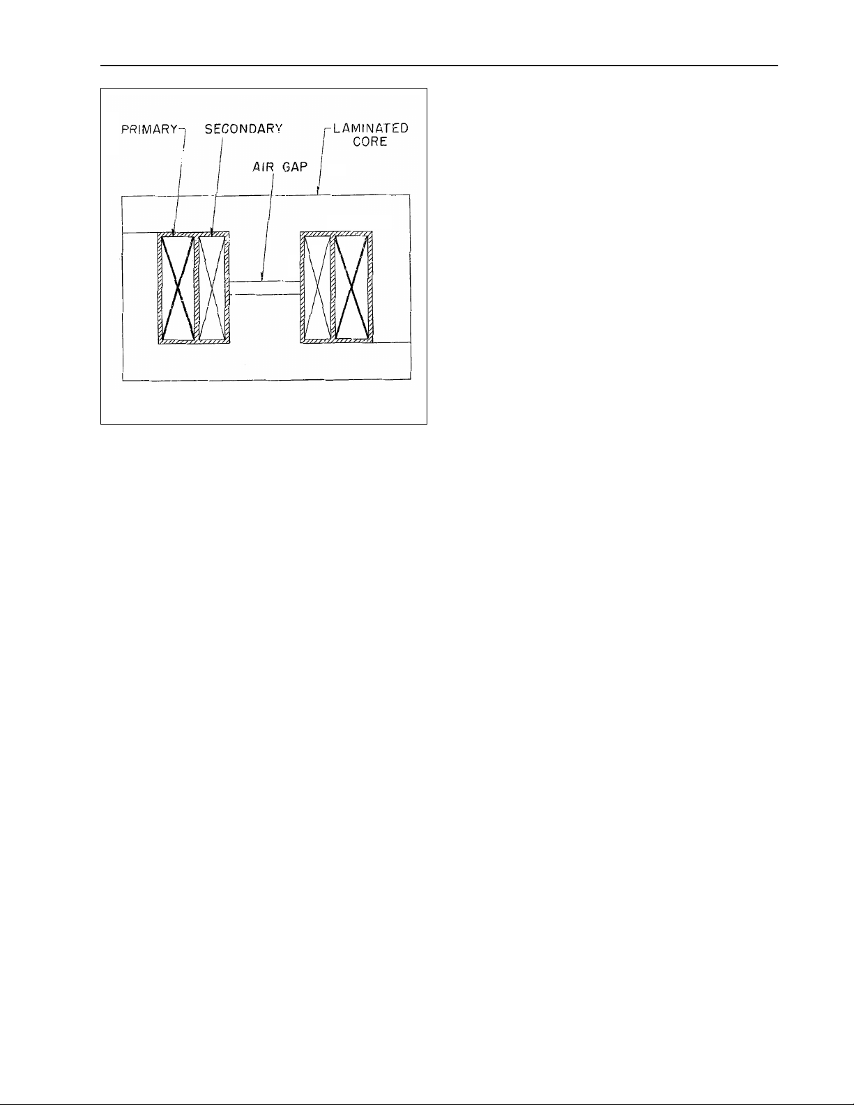
2.1 Compensator
The compensators, which are designated TA and
TC, are two (2) winding air-gap transformers (Fig-
ure 2). The primary or current winding of the
long-reach compensator TA has seven taps which
terminate at the tap block. They are marked 2.4,
3.16, 4.35, 5.93, 8.3, 11.5, 15.8. The primary winding of the short-reach compensator TC also has
seven taps which terminate at this tap block. They
are marked 0.0, 0.91, 1.27, 1.82, 2.55, 3.64, 5.1.
Voltage is induced in the secondary which is proportional to the primary tap and current magnitude.
This proportionality is established by the cross sectional area of the laminated steel core, the length of
an air gap which is located in the center of the coil,
and the tightness of the laminations. All of these
factors which influence the secondary voltage proportionality have been precisely set at the factory.
All possible contingencies which may arise during installation, operation or maintenance, and all details and
variations of this equipment do not purport to be covered by these instructions. If further information is desired
by purchaser regarding this particular installation, operation or maintenance of this equipment, the local ABB
Power T&D Company Inc. representative should be contacted.
Printed in U.S.A.
Page 2

41-748.21C
Front View Rear View
Figure 1. Type KLF Relay
The clamps which hold the laminations should not
be disturbed by either tightening or loosening the
clamp screws.
The secondary winding is connected in series with
the relay terminal voltage. Thus voltage, which is
proportional to the line current, is added vectorially
to the relay terminal voltage.
2.2Auto-Transformer
The auto-transformer has three taps on its main
winding, S, which are numbered 1, 2, and 3 on the
tap block. A tertiary winding M has four taps which
may be connected additively or subtractively to
inversely modify the setting by any value from -15
to +15 percent in steps of 3 percent.
2
The sign of M is negative when the R lead is above
the L lead. M is positive when L is in a tap location
which is above the tap location of the R lead. The
M setting is determined by the sum of per unit values between the R and L lead. The actual per unit
values which appear on the tap plate between taps
are 0,.03,.06, and.06.
The auto-transformer makes it possible to expand
the basic ranges of the long and the short reach
compensators by a multiplier of . Any relay
S
-------------1 M±
ohm setting can be made within±1.5 percent from
2.08 ohms to 56 ohms for the long-reach and
from.79 ohms to 18 ohms for the short-reach.
Page 3
Sub 1
185A181
Figure 2. Compensator Construction
2.3 Impedance Tripping Unit
The distance unit is a four pole induction cylinder
type unit. The operating torque of the unit is proportional to the product of the voltage quantities
applied to the unit and the sine of the phase angle
between the applied voltages. The direction of the
torque depends on the impedance phasor seen by
the relay with respect to its characteristic circle.
Mechanically, the cylinder unit is composed of four
basic components: A die-cast aluminum frame,
and electromagnet, a moving element assembly,
and a molded bridge. The frame serves as a
mounting structure for the magnetic core. The
magnetic core which houses the lower pin bearing
is secured by the frame by a locking nut. The bearing can be replaced, if necessary, without having
to remove the magnetic core from the frame.
The electromagnet has two sets of two series connected coils mounted diametrically opposite one
another to excite each set of poles. Locating pins
on the electromagnet are used to accurately position the lower pin bearing, which is mounted on the
frame, with respect to the upper pin bearing, which
is threaded into the bridge. The electromagnet is
secured to the frame by four mounting screws.
The moving element assembly consists of a spiral
spring, contact carrying number, and an aluminum
cylinder assembled to a molded hub which holds
the shaft. The hub to which the moving-contact
41-748.21C
arm is clamped has a wedge and cam construction, to provide low-bounce contact action. A
casual inspection of the assembly might lead one
to think that the contact arm bracket does not
clamp on the hub as tightly as it should. However,
this adjustment is accurately made at the factory
and is locked in place with a lock nut and should
not be changed. Optimum contact action is
obtained when a force of 4 to 10 grams pressure
applied to the face of the moving contact will make
the arm slip from the condition of reset to the point
where the clamp projection begins to ride up on
the wedge. The free travel can vary between 15° to
20°.
The shaft has removable top and bottom jewel
bearings. The shaft rides between the bottom pin
bearing and the upper pin bearing with the cylinder
rotating in an air-gap formed by the electromagnet
and the magnetic core. The stops are an integral
part of the bridge.
The bridge is secured to the electromagnet and
frame by two mounting screws. In addition to holding the upper pin bearing, the bridge is used for
mounting the adjustable stationary contact housing. This stationary contact has .002 to .006 inch
follow which is set at the factory by means of the
adjusting screw. After the adjustment is made the
screw is sealed in position with a material which
flows around the threads and then solidifies. The
stationary contact housing is held in position by a
spring type clamp The spring adjuster is located on
the underside of the bridge and is attached to the
moving contact arm by a spiral spring. The spring
adjuster is also held in place by a spring type
clamp.
When contacts close, the electrical connection is
made through the stationary contact housing
clamp, to the moving contact, through the spiral
spring and out to the spring adjuster clamp.
2.4 Directional Unit
The directional unit is an induction cylinder unit
operating on the interaction between the polarizing
circuit flux and the operating circuit flux.
Mechanically, the directional unit is composed of
the same basic components as the distance unit: a
die-cast aluminum frame, an electromagnet, a
moving element assembly, and a molded bridge.
The electromagnet has two series-connected
polarizing coils mounted diametrically opposite
one another; two series-connected operating coils
3
Page 4
41-748.21C
* Sub 4
3531A58
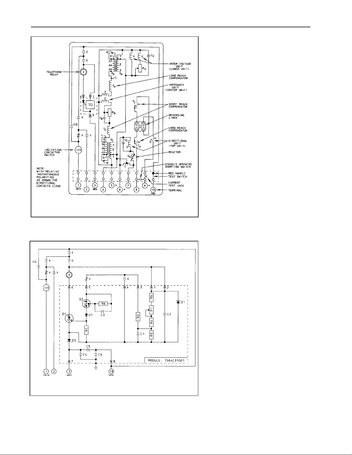
Figure 3. Internal Schematic of Type KLF Relay in FT-41 Case
*Denotes Change
mounted diametrically opposite one
another; two magnetic adjusting plugs;
upper and lower adjusting plug clips, and
two locating pins. The locating pins are
used to accurately position the lower pin
bearing, which is threaded into the
bridge. The electromagnet is secured to
the frame by four mounting screws.
The moving element assembly consists
of a spiral spring, contact carrying member, and an aluminum cylinder assembled to a molded hub which holds the
shaft. The shaft has removable top and
bottom jewel bearings. The shaft rides
between the bottom pin bearing and the
upper pin bearing with the cylinder rotating in an air gap formed by the electromagnet and the magnetic core.
The bridge is secured to the electromagnet and frame by two mounting screws.
In addition to holding the upper pin bearing, the bridge is used for mounting the
adjustable stationary contact housing.
The stationary contact housing is held in
position by a spring-type clamp. The
spring adjuster is located on the underside of the bridge and is attached to the
moving contact arm by a spiral spring.
The spring adjuster is also held in place
by a spring type clamp.
2.5 Undervoltage Unit
The voltage unit is an induction-cylinder
unit.
Mechanically, the voltage unit is composed, like the directional unit, of four
components: A die-cast aluminum frame,
and electromagnet, a moving element
assembly, and a molded bridge.
The electromagnet has two pairs of voltage coils. Each pair of diametrically
opposed coils is connected in series. In
addition one pair is in series with an
adjustable resistor. These sets are in
Sub 4
3533A29
parallel as shown in Figure 3. The
adjustable resistor serves not only to
shift the phase angle of the one flux with
Figure 4. KLF Time Delay Schematic
respect to the other to produce torque,
but it also provides a pickup adjustment.
4
Page 5
41-748.21C
Sub 3
1487B21
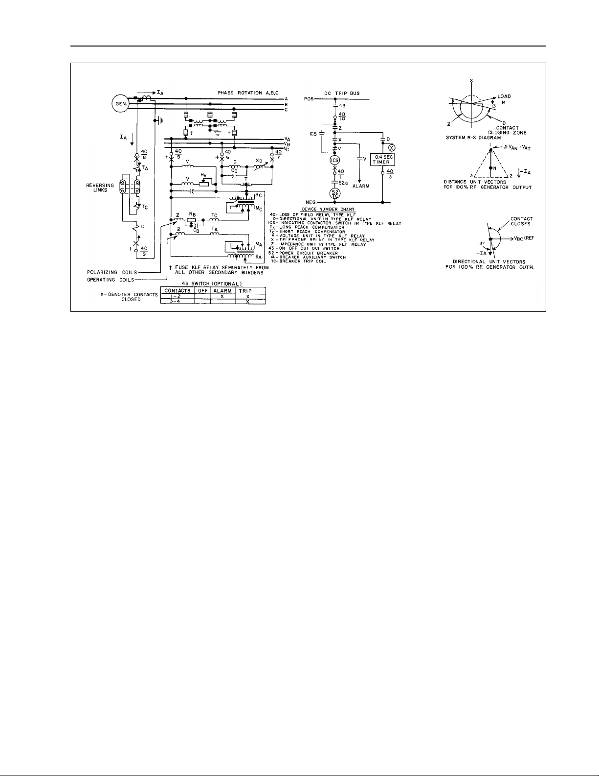
Figure 5. External Schematic of Type KLF Relay
Otherwise the undervoltage unit is similar in its
construction to the directional unit.
2.6 Solid State Time Delay Circuit
The telephone relay (x) is energized through a
solid state time delay circuit (TD) as shown in Fig-
ure 3. The solid state time delay circuit shown in
Figure 4 consists basically of an adjustable inte-
grating RC circuit with quick reset. The RC circuit
is adjusted to provide the voltage level to trigger
the SCR through a multi-layer silicon switch. The
SCR in turn energizes the relay.
2.7 Indicating Contactor Switch Unit (ICS)
The dc indicating contactor switch is a small clapper-type device. A magnetic armature, to which
leaf-spring mounted contacts are attached, is
attracted to the magnetic core upon energization of
the switch. When the switch closes, the moving
contacts bridge two stationary contacts, completing the trip circuit. Also during this operation two
fingers on the armature deflect a spring located on
the front of the switch, which allows the operation
indicator target to drop. The target is reset from the
outside of the case by a push rod located at the
bottom of the cover. The front spring, in addition to
holding the target, provides restraint for the armature and thus controls the pickup of the switch.
3. OPERATION
The relay is connected and applied to the system
as shown if Figure 5. The directional unit closes its
contacts for lagging VAR flow into the machine. Its
zero torque line has been set at -13° from the
R-axis. Its primary function is to prevent operation
of the relay during external faults. The impedance
unit closes its contacts when, as a result of reduction in excitation, the impedance of the machine as
viewed from its terminals is less than a predetermined value. The operation of both impedance and
directional units energize the time delay circuit
which operates the X unit after .4 ±.05 seconds.
The operation of impedance, directional and X unit
sounds an alarm, and the additional operation of
the under voltage unit trips the machine. This time
delay is to insure positive contact coordination
under all possible operating conditions. During a
seismic event which exposes the relay to a ZPA
level of 5.7g, the operate time of the X unit may
vary from .25 second to 1.25 seconds due to
bounce induced in the Z and the D contacts. During normal conditions, all contacts are open.
3.1 Principle of Distance Unit Operation
The distance unit is an induction cylinder unit having directional characteristics. Operation depends
on the phase relationship between magnetic fluxes
in the poles of the electromagnet.
5
Page 6
41-748.21C
Sub 2
185A331
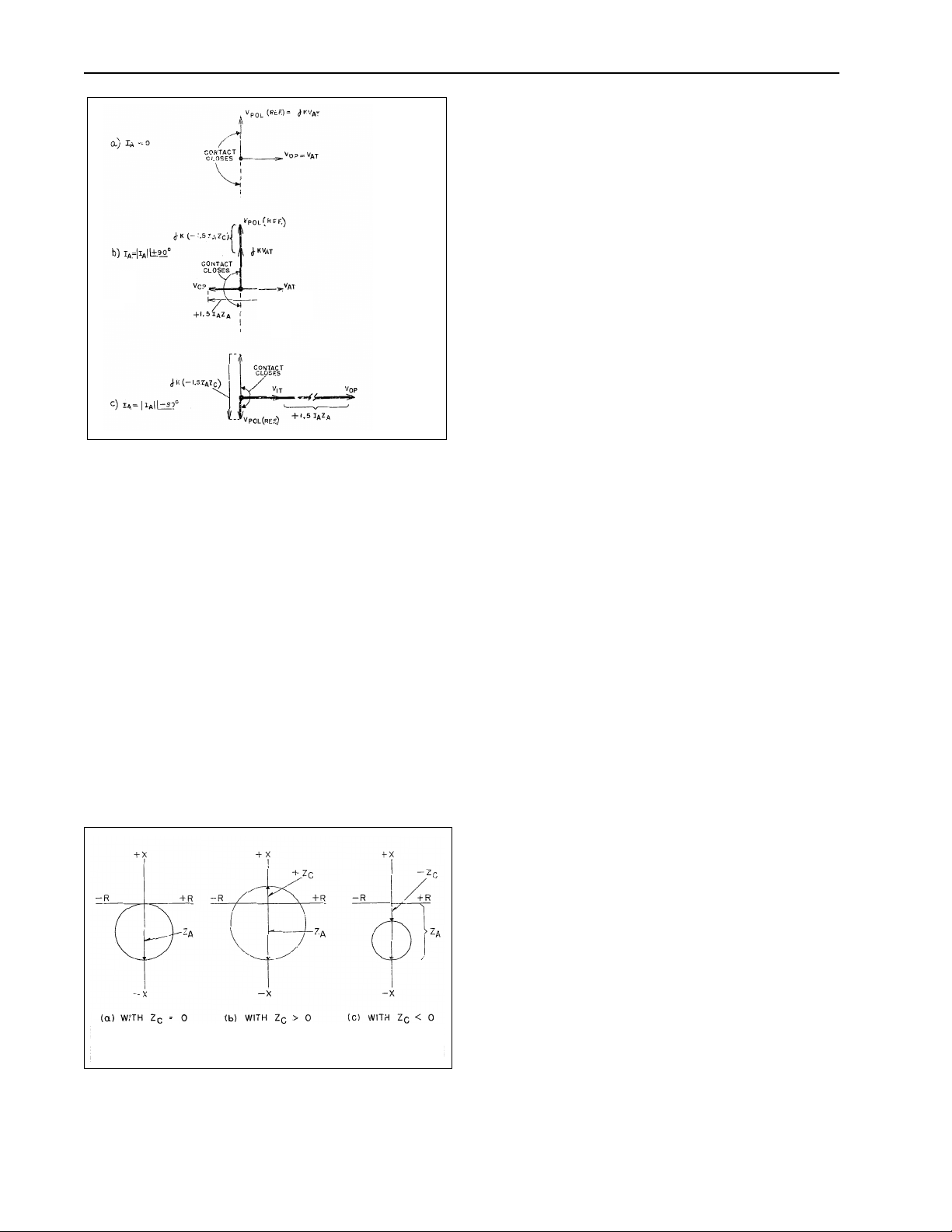
Figure 7. Effect of Compensator Voltages
(ZC is positive)
One set of opposite poles, designated as the operating poles are energized by voltage V1Tmodified
by a voltage derived from the long reach compensator TA. The other set of poles (polarizing) are
energized by the same voltage V1T except modified by a voltage derived from the short reach com-
pensator TC. The flux in the polarizing pole is so
adjusted that the unit closes its contacts whenever
flux in the operating set of poles leads the flux in
the polarizing set.
The voltage V1T is equal to:
V120.5 V
+ 1.5 V
==
1T
23
1N
(1)V
As shown in Figure 5, one-half of V23, voltage is
physically derived in the relay at midtap of a reac-
tor connected across voltage V23.
Reach of the distance unit is determined by com-
pensators TA and TC as modified by auto-transformer settings. Compensators TA and TC are
designed so the their mutual impedances ZA and
ZC have known and adjustable values as
described below under “CHARACTERISTICS” and
“SETTING CALCULATIONS”. The mutual imped-
ance of a compensator is defined here as the ratio
of secondary induced voltage to primary current
and is equal to T. Each secondary compensator
voltage is in series with the voltage V1T. Compen-
sator voltages are equal to 1.5 I1 ZAfor long reach
compensator and 1.5 I1 ZC for short reach compensator, where I, is the relay current.
Figure 6 shows how the compensation voltages
1.5 I1 ZA and 1.5 I1 ZC influence the R-X circle.
Notice that ZA independently determines the “long
reach”, while ZC independently determines the
“short reach”. With the reversing links in the nor-
mal position (+ZC) the circle includes the origin;
with the opposite link position (-ZC) the circle
misses the origin. The following paragraphs
explain this compensator action.
Referring to Figure 5 notice that resistor RB and
capacitor CB cause the polarizing voltage to be
shifted 90° in the leading direction. Thus, when the
current is zero, polarizing voltage V
leads the
POL
operating voltage VOP by 90° and of sufficient
magnitude to operate the relay. This means the
apparent impedance is along the X axis. Notice in
Figure 7(b) that the ZA compensation reverses the
operating voltage phase position. The relay balances when this voltage is zero. Note also this balance is unaffected by the ZC compensation, since
this compensation merely increases the size of
V
.
POL
Sub 2
185A182
Figure 6. R-X Diagram Characteristics with various
ZC - Compensator Settings.
6
For lagging current conditions notice Figure 7(c)
illustrates how V
is reversed by the ZC com-
POL
pensation. In this case the ZA compensation has
no effect of the balance point. This explains why
the reach point is fixed independently by ZC.
Figure 7 assumes that ZC is positive (circle
includes origin). If the current coil link is reversed,
Page 7

41-748.21C
the compensation becomes +1.5 IZC. In Figure
7(b) this change would result in V
POL
being
reduced rather than increased by the compensation. As the current increases V
will finally be
POL
reversed establishing restraining torque. Thus, the
current need not reverse in order to obtain a “short
reach” balance point. Instead the apparent impedance need only move towards the origin in the - X
circle region to find the balance point. Therefore
the circle does not include the origin with a
reversed link position.
4. CHARACTERISTICS
The type KLF relay is available in one range.
4.1 Distance Unit
The distance unit can be set to have characteristic
circles that pass through origin, include it, or
exclude it, as shown in Figure 6.
The ZAand ZC values are determined by compensator settings and modified by auto-transformer
settings, S, L, and R. The impedance settings in
ohms reach can be made for any value from 2.08
to 56 ohms for ZA, and from 0.79 ohm to 18 ohms
for ZC in steps of 3 percent.
The taps are marked as follows:
T
-------------------------------------------------------------------------------------
2.4 3.16 4.35 5.93 8.3 11.5 15.8,,,,,,
-------------------------------------------------------------------------------------
0.0 0.91 1.27 1.82 2.55 3.64 5.1,,,,,,
,()
S
ASC
----------------------
123,,
---------------------------------------------------------------------------------
values between taps .03, .06, .06±
A
T
C
MAMC,()
age. This voltage is equal to 1.5 V1N voltage. The
contacts can be adjusted to close over the range of
65 to 85 percent of normal system voltage. The
dropout ratio of the unit is 98 percent or higher.
4.4 Trip Circuit
The main contacts will safely close 30 amperes at
250 volts dc and the seal-in contacts of the indicating contactor switch will safely carry this current
long enough to trip a circuit breaker.
4.5 Trip Circuit Constant
Indicating Contactor Switch (ICS)
0.2 ampere rating
1.0 ampere rating
2.0 ampere rating
8.5 ohm dc resistance
.37 ohms dc resistance
.1 ohm dc resistance
4.6 Burden
Current
5 amps, 60 Hz
T
& T
A
C
Settings VA
MAX.
MIN.
Phase AB
S
= SC VA
A
1
2
3
18.0
14.4
13.9
Rating Watts + Rated
125
250
18.6
3.8
POTENTIAL
120 VOLTS, 60 Hz
Angle
of LAG
°
2
31°
39°
dc Circuit
Angle
of LAG
°
77
51°
Phase BC
Angle VA of LAG
2.6
5.9
6.6
12°
38°
42°
3.9
7.8
4.2 Directional Unit
The KLF relay is designed for potential polarization
with an internal phase shifter, so that maximum
torque occurs when the operating current leads the
polarizing voltage by approximately 13 degrees.
The minimum pickup has been set by the spring
tension to be approximately 1 volt and 5 amperes
at maximum torque angle.
4.3 Undervoltage Unit
The undervoltage unit is designed to close its contacts when the voltage is lower than the set value.
The undervoltage unit is energized with V1T-volt-
4.7 Thermal Ratings
Potential: 132 volts (L-L) continuous
Current: 8 amperes continuous
200 amperes for 1 second
5. SETTING CALCULATIONS
5.1 General Setting Recommendations
The KLF relay may be applied as a single-zone
device, or two relays may be used to provide
two-zone protection. The single-zone setting may
be fully offset (Zone 1) or may include the origin
(Zone 2). The two-zone application would require a
7
Page 8

41-748.21C
Zone 1 KLF and a Zone 2 KLF, approximately
equivalent to two-zone step-distance line protection. A generalized external schematic, which is
applicable to either Zone 1 or Zone 2 relays is
shown in Figure 10. The recommended settings
and relative advantages of these varioi4us configurations are summarized on Table 1.
The single-zone and two-zone setting recommendations are modified when two or more machines
are bussed at the machine terminals. The voltage
and time delay considerations are treated in detail
in other sections of this leaflet. The recommended
settings are outlined in Table 2.
5.2 Zone 2 Setting Calculations (Distance Unit)
Set the distance unit to operate before the
steady-state stability limit is exceeded. Also, to
allow maximum output without an alarm, set the
distance unit to allow the machine to operate at
maximum hydrogen pressure and 0.95 per unit
voltage (lowest voltage for which the capability
curve machine cannot be realized without exceeding the steady-state stability limit, set the distance
unit to operate before the steady-state limit is
exceeded. Capability curves similar to Figure 8 are
obtained from the generator manufacturer.
To determine the desired setting convert the capability curve Figure 8 of the impedance curve Figure
Since the angle remains the same, the impedance
plot conversion is:
Z1.4 33.6°, as shown in Figure 9.–∠=
After plotting the steady-state stability limit and the
machine capability curves on the R-X diagram, plot
the relay circle between the stability limit and the
capability curve. (Note in Figure 9 that the relay
circle cannot be plotted within the 60# -VT = 0.95
curve, since the machine is beyond the
steady-state stability limit for these conditions.)
This plot defines the desired reach ZA and radius
R of the relay circle. Then use the following procedure to select tap settings.
Z
base
---------------------------------kva()R
1000 kv()2R
C
V
ohms=
(2)
where
Z
= one per unit primary ohms/
base
as seen from the relay.
kv = rated phase-to-phase voltage
of the machine.
kVA = rated kVA of the machine.
R
R
= the current transformer ratio.
C
= the potential transformer ratio.
V
9 by calculating , where VT is the per unit
|VT2|
--------------------KVA()
C
terminal voltage and (KVA)c is the per unit output.
The angle of each point on the impedance curve
(from the horizontal) is the same angle as the corresponding point on the capability curve.
For example, from Figure 8, an output of 0.6 per
unit KW on 30# hydrogen pressure curve is -0.4
per unit reactive KVA. Therefore,
KVA()
C
0.6()20.4–()
+=
2
= 0.715 per unit
0.4–
and,
θTan 1
– 33.6°–==
----------
0.6
Converting to the impedance curve:
2
V
Z
T
==
--------------------KVA()
C
1.0
-------------
0.715
2
= 1.4 per unit
The actual settings, ZA and ZC, are:
ZA=(ZA per unit) x (Z
ZC=(ZC per unit) x (Z
= (ZR - ZA) x (Z
base
) (3)
base
)
base
) (4)
Where R = radius of circle in per unit.
The tap-plate settings are made according
to equations:
ZAor Z
()
C
=
TS
-------------1 M±
(5)
where:
T = compensator tap value.
S = auto-transformer primary tap value.
M = auto-transformer secondary tap
value.
(M is a per unit value determined by taking the sum
of the values between the L and the R leads. The
sign is positive when L is above R and acts to
8
Page 9

41-748.21C
2
lower the Z setting. The sign is negative when R is
above L and acts to raise the Z setting).
The following procedure should be followed to
obtain an optimum setting of the relay:
1. Select the lowest tap S which give a prod-
uct of 18.6SA greater than desired ZA and a product of 6SC greater than desired Z
C
2. Select a value of M that will most nearly
make it equal to:
TS
M
------- Z
1.–=
If the sign is negative, then the M taps are connected with the R lead above the L lead to raise
the setting.
5.3 Sample Calculations
Assume that a KLF relay is to be applied to the following machine:
3-phase, 60 hertz, 3600 rpm, 18 kV, rated at 0.9
pf, 183,500 KVA at 45#H2.
RC= 1400/1 RV= 150/1
Step 3:
TAS
-------------Z
A
M
A
1–
15.8 2×
-------------------
27.6
1– 1.145 1– +.145=====
Set M = +.15. Place R lead in 0, L lead in
upper .06. The relay setting is now:
ActualZ
TAS
--------------
A
1 M±
A
15.8 2×
-------------------
1 0.15+
31.6
----------
1.15
27.5== ==
This is 99.7% of the desired setting.
To set ZC= 3.29 ohms:
Step 1: The lowest tap SC for 6SC greater than
3.29 is SC = 1.
Set SC = 1
Step 2: TC nearest to
329,
----------- -
1
3.29 is 3.64=
Set TC in 3.64 tap.
Step 3:
M
TCS
C
---------------
C
Z
C
1–
3.64 1×
-------------------
3.29
1– 1.107 1– +.107== ==
If the recommended setting from Figure 9 is used:
ZA per unit = 1.68
ZC per unit = 2R - ZA = 2 x 0.94 - 1.68 = 0.20
(The relay circle in Figure 9 was obtained by trial
and error using a compass to get the desired
radius and offset.)
(1)
2
× 1400×
16.48Ω== =
se
1000 kv()
----------------------------- -
()R
kva
V
R
1000 18()
c
------------------------------------------------- -
183 500 150×,
(2)
Z
Z
A
per unit()Z
A
base
(1.68 ) 16.48()27.6Ω===
(3)
Z
Z
C
per unit()Z
C
()0.20()16.45()3.29Ω===
base
To set ZA= 27.6
Step 1: The lowest tap SA for 18.6 SA greater
than ZA = 27.6 is 2. Set SA in tap 2.
Step 2: TA nearest to = 13.8 is TA= 15.8
27.6
----------
2
Set TA in 15.8 tap
Hence, the nearest MC value is + .12. Now set R
lead in 0.03 tap and L lead in the upper .06 tap.
(Since MC has plus sign lead L must be over R.)
T
S
Then, , or
Z
C
C
----------------------
1M
+()
3.64 1×
C
-------------------
1 0.12+
C
3.25Ω===
98.8% of the desired value.
5.4 Undervoltage Unit
A. The undervoltage unit is usually set to a value
corresponding to the minimum safe system voltage for stability. This voltage depends on many
factors, but is usually between 70 and 80 percent
of normal system voltage. The undervoltage unit
is set at the factory for 77% of normal system
voltage, or 92 V
(equivalent to 80 volts on the
L-L
undervoltage unit). In cases where each generator is equipped with its own transformer (unit
connected system) the standard factory setting is
usually satisfactory for the undervoltage unit.
B. In applications where multiple units are con-
nected to the same bus, loss of field of one unit
may not depress the bus voltage to the point
where the undervoltage unit will operate if it has
the standard setting. The following recommenda-
9
Page 10

41-748.21C
TABLE 1
RECOMMENDED SETTINGS FOR KLF RELAY
ZONE 1 (ALONE) ZONE 2 (ALONE) BOTH ZONE 1 AND 2
IMPEDANCE SETTING
VOLTAGE SETTING
TD-1
TD-2
ADVANTAGES
See Figure 11 See Figure 12 See Figures 11 & 12
(a) Contact shorted or
(b) Set at 80% for
security
1/4 to 1 sec
(1 sec preferred)
Not required for
(a) above. For
(b) above use 1 Min.
Less sensitive to
stable system swings
1) More sensitive to
2) Can operate on
3) Provide alarm
80%
1/4 to 1 sec
(1 sec preferred)
1 Min.
LOF condition
partial LOF
features for
manual operation
Zone 1 voltage contact
shorted with Zone 2 set
at 80%
Zone 1 timer = 1/4 sec
Zone 2 timer = 1 sec
1 Min
(1) Same as (1), (2)
and (3) at left.
(2) Provides back-up
protection
SPECIAL SETTINGS FOR MULTI MACHINES BUSSED AT MACHINE TERMINALS
IMPEDANCE SETTING
VOLTAGE SETTING
TD-1
TD-2
TABLE 2
ZONE 1 (ALONE) ZONE 2 (ALONE) BOTH ZONE 1 AND 2
See Figure 11 See Figure 12 See Figures 11 & 12
(a) Contact shorted or
(b) Set at 87% for
security
1/4 to 1 sec
(1 sec preferred)
Not required for
(a) above. For
(b) above use 10 sec
for cond. cooled,
25 sec for conv.
cooled
10 sec for cond. cooled.
25 sec for conv. cooled.
87%
1/4 to 1 sec
(1 sec preferred)
Zone 1 voltage contact
shorted with Zone 2 set
at 87%
Zone 1 timer = 1/4 sec
Zone 2 timer = 1 sec
10 sec for cond. cooled.
25 sec for conv. cooled.
10
Page 11

41-748.21C
tions should be considered:
1. For cross-compound turbine generator applications, the dropout voltage (i.e., the voltage
at which the back contact of the undervoltage unit closes) of the undervoltage unit
should be set for 87% of normal voltage
(equivalent to 90 volts on the undervoltage
unit).
2. For waterwheel generator applications, with
multiple machine tied to a common bus, the
dropout voltage of the undervoltage unit
should be set at 87%.
3. For all applications where the alarm function
is not to be used the undervoltage unit contact should be jumped (shorted).
4. For industrial applications, with two or more
generators on the same bus, the undervoltage unit contact should be jumped (shorted)
and the alarm circuit not used.
5. For small Synchronous condenser and large
motor applications, the undervoltage unit
contact should, in general, be jumped
(shorted), and the alarm circuit not used. In
special cases the machine may be treated
as in 2, above, where knowledge exists of
expected undervoltage level.
6. For gas turbine units, with high generator
impedance, the undervoltage unit may not
operate. For these applications the undervoltage contacts should be short circuited.
C. The desired undervoltage unit setting is com-
puted by:
Setting = VIT = 1.5 V
IN
where VINis phase-to-neutral voltage.
NOTE: An electrical check of this particular
setting is outlined in this instruction
leaflet, under the heading “Acceptance
Check”.
5.5 Time Delay Considerations
It may be conservatively stated that the rotor structure and stator heating, as a result of a shorted
field can be tolerated for 10 seconds on a conductor-cooled machine and 25 seconds for a conventional machine. This time may be as low as 5
seconds for an open field (as opposed to a field
closed through a field discharge resistor or an
exciter armature) and as high as one minute where
the concern is protection of an adjacent tandem
compound unit against partial loss-of-excitation in
the faulted machine.
In view of the above considerations, it is often
desirable to use an external timer in conjunction
with the KLF Relay. The following examples are
applications where an external timer would be
desirable:
1. Cross-compound units, with undervoltage
unit setting of 90 volts, should use an external timer to assure tripping before thermal
damage can result. The timer is energized at
the alarm output and should be set for 10
seconds for a cross-compound conductor
cooled machine. For a conventionally cooled
cross-compound machine, the external timer
should be set for 25 seconds.
As an alternative to this, the KLF with
shorted undervoltage contacts may be
applied and the alarm feature not used. With
this arrangement, tripping takes place after
the 0.4 second time delay provided by the X
unit in KLF relay.
2. Machines connected to a common high voltage bus may be protected against loss of
voltage due to loss-of-excitation in an adjacent machine by using a one minute timer
driven by the alarm output of the loss-of-field
relay.
3. In some critical applications 2 zone
loss-offield protection may be desirable. In
this case, the Zone 1 KLF impedance circle
should be small and fully offset in the negative reactance region. The long-reach should
be set equal to synchronous reactance, Xd.
The short-reach should be set equal to
one-half transient reactance, XD1/2. The trip
circuit should trip directly, with no time delay.
The alarm circuit should operate a timer
which may be set from 0.4 - 1.0 seconds,
depending on user preference. If the condition persists, this timer permits tripping.
The second-zone KLF may be set with a
larger impedance characteristic and will
detect partial loss-of-field conditions. A typical setting would be to just allow the machine
to operate at maximum hydrogen pressure
11
Page 12

41-748.21C
and 9.5 per unit voltage. If a low voltage condition occurs, it is recommended that tripping
be accomplished through a timer set for 0.6
second. Added to the X unit operate time of
0.4 second, this gives an overall time of 1.0
second. If the voltage is maintained, then the
alarm circuit should start a “last-ditch” timer.
This timer may be set anywhere from 10 seconds to one minute depending on machine
type and user preference.
5.6 Performance During Reduced Frequency
During major system break-ups, it is possible that
the generators may be called upon to operate at
reduced frequency for long periods of time. During
this condition the loss-of-field relay should be
secure and not over-trip for load conditions. The
KLF relay has a favorable characteristic during this
condition, since its tripping characteristic becomes
more secure during reduced frequencies, as
shown in Figure 13.
6. SETTING THE RELAY
The type KLF relay requires a setting for each of
the two compensators TA and TC, for each of the
two auto-transformers, primaries SA and SC, and
for the undervoltage unit.
6.1 Compensator (TA and TC)
Each set of compensator taps terminates in inserts
which are grouped on a socket and form approximately three quarters of a circle around a center
insert which is the common connection for all the
taps. Electrical connections between common
insert and tap inserts are made with a link that is
held in place with two connectors screws, one in
the common and one in the tap.
A compensator tap setting is made by loosening
the connector screw in the center. Remove the
connector screw in the tap end of the link, swing
the link around until it is in position over the insert
for the desired tap setting, replace the connector
screw to bind the link to this insert, and retighten
the connector screw in the center. Since the link
and connector screws carry operating current, be
sure that the screws are turned to bind snugly.
Compensator TC requires an additional setting for
including or excluding the origin of R-X diagram
from the distance unit characteristic. If the desired
characteristic is similar to that shown on Figure 6b,
the links should be set vertically in the + TC arrow
direction. If a characteristic similar to that shown in
Figure 6c is desired, set links horizontally in the TC arrow direction.
6.2 Auto-Transformer Primary (SA and SC)
Primary tap connections are made through a single
lead for each transformer. The lead comes out of
the tap plate through a small hole located just
below the taps and is held in place on the proper
tap by a connector screw.
An S setting is made by removing the connector
screw, placing the connector in position over the
insert of the desired setting, replacing and tightening the connector screw. The connector should
never make electrical contact with more than one
tap at a time.
6.3 Auto-Transformer Secondary (MA and MC)
Secondary tap connections are made through two
leads identified as L and R for each transformer.
These leads comes out of the tap plate each
through a small hole, one on each side of the vertical row of M tap inserts. The lead connectors are
held in place on the proper tap by connector
screws.
Values for which an M setting can be made are
from -.15 to +.15 in steps of .03. The value of a
setting is the sum of the numbers that are crossed
when going from the R lead position to the L lead
position. The sign of the M value is determined by
which lead is in the higher position on the tap
plate. The sign is positive (+) if the L lead is higher
and negative (-) if the R lead is higher.
Z M L Lead R Lead
0.87 TS
0.89 TS
0.92 TS
0.94 TS
0.97 TS
TS
1.03 TS
1.06 TS
1.1 TS
1.14 TS
1.18 TS
+.15
+.12
+.09
+.06
+.03
0
-.03
-.06
-.09
-.12
-.15
Upper .06
Upper .06
Lower .06
Upper .06
.03
0
0
Lower .06
0
.03
0
0
.03
0
Lower .06
0
0
.03
Upper .06
Lower .06
Upper .06
Upper .06
An M setting may be made in the following manner: Remove the connector screws so that the L
and R leads are free. Determine from the following
table the desired M value and tap positions. Neither lead connector should make electrical contact
with more than one tap at a time.
12
Page 13

41-748.21C
6.4 Undervoltage Unit
The voltage unit is calibrated to close its contact
when the applied voltage is reduced to 80 volts.
The voltage unit can be set to close its contacts
from 70 volts to 90 volts by adjusting the resistor
located next to the directional unit (to the left of the
upper operating unit). The spiral spring is not disturbed when making any setting other than the calibrated setting of 80 volts.
The undervoltage unit range of 70 to 90 volts is
equivalent to 80 to 104 V
(or 67% to 87% nor-
L-L
mal system voltage). This is because the voltage
on the unit is equal to 1.5 times V
L-N
.
6.5 Directional Setting
There is no setting to be made on the directional
unit.
6.6 Indicating Contactor Switch (ICS)
No setting is required on the ICS.
7. INSTALLATION
The relays should be mounted on switchboard
panels or their equivalent in a location free from
dirt, moisture, excessive vibration, and heat.
Mount the relay vertically by means of the four
mounting holes on the flange for semi-flush mounting or by means of the rear mounting stud or studs
for projection mounting. Either a mounting stud or
the mounting screws may be utilized for grounding
the relay. The electrical connections may be made
directly to the terminals by means of screws for
steel panel mounting of the terminal studs furnished with the relay for thick panel mounting. The
terminal studs may be easily removed or inserted
by locking two nuts on the stud and then turning
the proper nut with a wrench.
For detailed FT Case information refer to I.L.
41-076.
8. ADJUSTMENTS AND MAINTENANCE
The proper adjustments to insure correct operation
of this relay have been made at the factory. Upon
receipt of the relay, no customer adjustments,
other than those covered under “SETTINGS,”
should be required.
8.1 Performance Check
The following check is recommended to insure that
the relay is in proper working order: Relay should
be energized for at least one hour.
A. Distance Unit (Z)
1. Connect the relay as shown in Figure 14 with
the switch in position 2 and the trip circuit
deenergized.
2. Make the following tap settings:
TA= 11.5 TC= 2.55
SA=2 SC=1
MA= -.03 MC= -.09
TC link in middle block should be set for +T
direction.
This setting corresponds to ZA = 23.7, ZC = 2.80
Adjust the phase shifter for 90° current lagging
the voltage.
3. With the terminal voltage at 80 volts,
increase current until contacts just close.
This current should be within ±3% of 2.25
amps (2.32 - 2.18 amps). This value corresponds to 1.5 ZA setting since the voltage as
applied to terminals 4 and 5 is equivalent to
1.5 VIN voltage, or
V
Z
--------- -
A
I
1N
1
80
1
× 23.7Ω== =
------ -
--------- -
1.5
2.25
4. Adjust phase shifter for 90° current leading
the voltage.
5. With the terminal voltage at 80 volts increase
current until contacts just close. This current
should be within ±3% of 19.0 amps. (19.6 -
18.4 amps.) This value corresponds 1.5Z
setting for the same reason as explained
above.
5. Contact Gap
The gap between the stationary contact and
moving contact with the relay in deenergized
position should be approximately.040”.
B. Directional Unit Circuit (D)
1. Connect the relay as shown in Figure 14 with
the switch in position 1 and the trip circuit
deenergized.
2. With a terminal voltage of 1 volt and 5
amperes applied, turn the phase shifter to
13° (current leads voltage). The contacts
should be closed. This is the maximum
torque position.
3. Raise the voltage to 120 volts and vary the
phase shifter to obtain the two angles where
C
C
13
Page 14

41-748.21C
the moving contact just makes with the left
hand contact. These two angles (where
torque reverses) should be where the current
leads the voltage by 283° and 103°, ± 4°.
4. Contact Gap
The gap between the stationary contact and
moving contact with the relay in deenergized
position should be approximately.020”.
C. Undervoltage Circuit
1. Connect the relay as shown in Figure 14 with
switch in position 2 and the trip circuit deenergized.
2. Decrease the voltage until the contacts close
to the left. This value should be 80 ± 3%
volts.
D. Reactor Check
Apply 120 volts ac across terminals 6 and 7. Mea-
sure voltage from terminal 6 to 4 and 7 to 4. These
voltages should be equal to each other within
± 1volt.
E. Solid State Time Delay Circuit
Then release the contacts and observe that they
open positively.
All contacts should be checked and cleaned if necessary. A contact burnisher Number 182A836H01
is recommended for this purpose. The use of abrasive material for cleaning contacts is not recommended, because of the danger of embedding
small particles in the face of the soft silver and
thus impairing the contact.
8.3 Repair Calibration
Relay should be energized for at least one hour.
A. Auto-transformer check
Auto-transformers may be checked for turns ratio
and polarity by applying ac voltage to terminals 4
and 5 and following the procedure below.
1. Set SA and SC on tap number 3. Set the “R”
leads of MA and MC all on 0.0 and disconnect the “L” leads. Adjust the voltage for 90
volts. Measure voltage from terminal 5 to the
tap #1 of SA. It should be 30 voltages (± 1).
From terminal 5 to tap #2 of SA should be 60
volts. The same procedure should be followed for taps #1 and #2 of SC.
Block the contacts of the Z unit closed. Apply 125
volts dc with positive at terminal 10 and negative at
terminal 3. Manually close the contacts of the D
unit. Using oscilloscope measure the time delay by
observing the voltage block waveform between the
relay terminal 3 (-) and terminal 1 (+). Operate time
should be 0.4 ± .05 second.
F. Indicating Contactor Switch (ICS)
Close the main relay contacts and pass sufficient
dc current through the trip circuit to close the contacts of the ICS. This value of current should not
be greater than the particular ICS nameplate rating. The indicator target should drop freely.
Repeat above except pass 85% of ICS nameplate
rating current. Contacts should not pickup and target should not drop.
8.2 Routine Maintenance
All relays should be inspected periodically. They
should receive a “Performance Check” at least
once every year or at such other time intervals as
may be dictated by experience to be suitable to the
particular application. A minimum suggest check
on the relay system is to close the contacts manually so that the breaker trips and the target drops.
2. Set SA and SC on 1 and adjust the voltage at
the relay terminals for 100 volts. Measure
voltage drop from terminals 5 to each of the
MA and MC taps. This voltage should be
equal to 100 (± 1) plus the sum of values
between R and tap being measured. Example 100 (1 + .03 +.06) = 109 volts
Transformers that have an output different
from nominal by more than 1.0 volt probably
have been damaged and should be
replaced.
B. Distance Unit (Middle Unit) Calibration
Make the following tap plate settings.
TA = 15.8; TC = 5.1
SA = SC = 1
Make MA= MC = -.15 settings:
“L” lead should be connected to the “O” insert.
“R” lead should be connected to the upper “.06”
insert. (-.03-.06 - .06 = -.15 between L & R)
For the most accurate calibration preheat relay
for at least an hour by energizing terminals 5, 6,
14
Page 15

41-748.21C
& 7 with 120 volts, 3 phase.
The links in the middle tap block should be set
for the +TC direction.
1. Contact Gap Adjustment
The spring type pressure clamp holding the
stationary contact in position should not be
loosened to make the necessary gap adjustments.
With moving contact in the opened position,
i.e., against right stop on bridge, screw in
stationary contact until both contacts just
make (use neon light for indication). Then
screw the stationary contact away from the
moving contact 1
of .040”.
1
turn for a contact gap
/
3
2. Sensitivity Adjustment
Using the connections of Figure 14 apply 10
volts ac 90° lagging, to terminals 4 and 5
pass .420 amperes through current circuit
(terminals 9 and 8). The spiral spring is to be
adjusted such that the contacts will just
close. Deenergize the relay. The moving
contact should return to open position
against the right hand stop.
C. Impedance characteristic Check
1. Maximum Torque Angle
Adjust resistor RB (mounted on the back of
the relay) to measure 8800 ohms. Applying
100 volts ac to terminals 5 and 4 and passing 5.2 amperes, through the current circuit
turn the phase shifter until the moving contact opens. Turn the phase shifter back (few
degrees) until contacts close. Note degrees.
Continue to turn the phase shifter until contact closes again. Note degrees. The maximum torque angle should be (± 3°)
computed as follows:
Degrees to Close Contacts at Left +
Degrees to Close Contacts at Right
-------------------------------------------------------------------------------------
2
Adjust resistor RB until the correct maximum-torque angle is obtained.
2. Impedance Check
a. Adjust voltage to be 90 volts.
For current lagging 90° the impedance
unit should close its contacts at 3.12 –
3.35 amp.
Reverse current leads, the impedance
unit should close its contacts at 9.7 – 10.3
amperes.
b. Reverse the links in the middle tap block
to -TC position. Apply current of 10 amps.
The contacts should stay open. Reverse
current leads to original position. The contacts should open when current is
increased above 9.7 – 10.3 amperes.
Set links back to +TC position. Change S
A
and SC to setting “2”. Keeping voltage at
90 volts, 90° lagging, check pick-up current. It should be 1.56 – 1.68 amperes.
Now set the phase shifter so that voltage
leads the current by 90°. Impedance unit
should trip now at 4.85 – 5.15 amperes.
c. Set TA = 11.5, TC = 2.55, SA = 2, SC = 1,
MA = -.03 MC = -.09. Set voltage at 90
volts leading the current by 90°. Impedance unit should trip at 2.61 – 2.45 amp.
Reverse current leads. Pickup should be
20.8 –22.1 amp.
Change SA, SC = 3. Check pickup. It
should be 6.95 – 7.35 amps. Reverse current leads. Pick-up should now be 1.74 –
1.63 amps.
D. Directional Unit (Top Unit)
1. Contact Gap Adjustment
The spring type pressure clamp holding the
stationary contact in position should not be
loosened to make the necessary gap adjustments.
With moving contact in the open position,
i.e., against right stop bridge, screw in stationary contact until both contacts just make.
Then screw the stationary contact away from
90°=
the moving contact 3/4 of one turn for a contact gap of .022”.
2. Sensitivity Adjustment
With reactor X having its core screwed out
by about 1/8 inch apply 1.00 volt to terminals
6 and 7. Observing polarities as per schematic, and 5 amperes current leading the
voltage by 13°, the spiral spring is to be
15
Page 16

41-748.21C
adjusted such that the contacts will just
close. The adjustment of the spring is
accomplished by rotating the spring adjuster
which is located on the underside of the
bridge. The spring adjuster has a notched
periphery so that a tool may be used to
rotate it. The spring type clamp holding the
spring adjuster should not be loosened prior
to rotating the spring adjuster.
3. Plug adjustment for Reversing of Spurious
Torques
a. Set TC = 0.0. Connect a heavy current
lead from TA center link to terminal 8.
b. Short circuit terminals 6 and 7.
c. Screw in both plugs as far as possible
prior to starting the adjustment.
d. Apply 80 amps only momentarily, and the
directional unit need not be cooled during
initial rough adjustment. But, the direc-
tional unit should be cool when final
adjustment is made.
e. When relay contact closes to the left,
screw out the right hand plug until spuri-
ous torque is reversed.
f. When plug adjustment is completed check
to see that there is no closing torque when
relay is energized with 40 amps and volt-
age terminals 6 and 7 short-circuited.
4. Maximum Torque Angle Check
With 120 volts and 5 amperes applied, vary
the phase shifter to obtain the two angles
where the moving contacts just close. These
two angles (where torque reverses) should
be where the current leads the voltage by
283° ±4 and 103° ± 1. Readjust the reactor
Xd if necessary.
E. Undervoltage Unit (Lower Unit)
NOTE: The moving contact is in closed posi-
tion to the left when deenergized.
1. Contact Gap Adjustments
the moving contact (use neon light for indication) and then continue for one more complete turn.
b. R.H. (Normally Open) Contact Adjustment
With moving contact arm against the left
hand stationary contact, screw the right hand
stationary contact until it just touches the
moving contact. Then back the right hand
contact out two-thirds of one turn to give
0.020 inch contact gap.
2. Sensitivity Adjustment
a. Apply voltage to terminals 4 and 5. With the
adjustable resistor, which is located at the
upper left hand corner, set for maximum
resistance (2500 ohms) adjust the spring so
that contacts make (to the left) at 70 volts.
The contacts should open when unit is energized with 71 or more volts.
b. Relay is shipped with 80 volts setting. This is
accomplished by lowering resistance value
until contacts make at 80 volts and open
when unit is energized with 81 or more volts.
The spring should not be used for this setting.
F. Solid State Time Delay Circuit
Refer to Figure 4 for the following test.
a. Connect a jumper between the “D” contacts
(top unit) and connect a switch between the
D-contact and relay terminal 10.
b. Connect a scope probe, common and exter-
nal trigger to relay terminals 1, 3 and contact
“D” respectively.
c. Connect a rated dc power supply between
relay terminals 10 (+) and 3 (-).
d. Turn on the dc power supply and then turn
on the switch. The voltage at terminal 1
should jump from 0 to the rated voltage after
a time delay of 0.4± 10% seconds. A trimpot
on the PC board can be adjusted to obtain
the desired time delay from 0.3 to 0.5 seconds.
a. L.H. (Normally Closed) Contact Adjustment
With the moving contact arm in the closed
position, against left hand side of bridge,
screw the left-hand contact in to just touch
16
G. Indicating Contactor Switch (ICS)
Initially adjust unit on pedestal so that armature
fingers do not touch the yoke in the reset position.
This can be done by loosening the mounting screw
Page 17

41-748.21C
in the molded pedestal and moving the ICS in the
downward direction.
1. Contact Wipe. Adjust the stationary contacts
so that both stationary contacts make with
the moving contacts simultaneously and
wipe 1/64” to 3/64” when the armature is
against the core.
2. Target. Manually raise the moving contacts
and check to see that the target drops at the
same time as the contacts make or up to
1/16” ahead. The cover may be removed
and the tab holding the target reformed
slightly if necessary. However, care should
be exercised so that the target will not drop
with a slight jar.
3. Pickup. Unit should pickup at 98% of rating
and not pickup at 85% of rating. If necessary
the cover leaf springs may be adjusted. To
lower the pickup current use a tweezer or
similar tool and squeeze each leaf spring
approximately equal by applying the tweezer
between the leaf spring and the front surface
of the cover at the bottom of the lower window.
If the pickup is low, the front cover must be
removed and the leaf springs bent outward
equally.
2. Disconnect the L-leads of sections MA and
M
C
3. Pass 10 amperes ac current in terminal 9
and out of terminal 8.
4. Measure the compensator voltage with an
accurate high resistance voltmeter (5000
ohms/volt).
5. Compensator A-voltage should be checked
between lead L
and terminal 5.
A
For TA = 15.8 the voltage measured should
be 23.7 volts (±3%).
6. Compensator C voltage should be checked
between lead LC and the fixed terminal on
the resistor which is mounted in the rear.
For TC = 5.1, the voltage should be 76.5
volts (±3%).
7. For all other taps the compensator voltage is
1.5IT (±3%).
Where I = relay current
T = tap setting
H. Compensator Check
Accuracy of the mutual impedance T of the com-
pensators is set within very close tolerances at factory and should not change under normal
conditions. The mutual impedance of the compensators can be checked with accurate instruments
by the procedure outlined below:
1. Set TA on the 15.8 tap
TC on the 5.1 tap
9. RENEWAL PARTS
Repair work can be done and the relay recertified
most satisfactorily at the factory. However, interchangeable parts can be furnished to the customers who are equipped for doing repair work. When
ordering parts, always give the complete nameplate data. Note that replacement parts are not
“certified” and repair work done outside the factory
can not be certified by ABB.
17
Page 18

41-748.21C
18
Sub 2
185A183
Figure 8. Typical Machine Capability Curves
Page 19

41-748.21C
Sub 2
185A184
Figure 9. Typical Machine Capability Curves and Sample KLF Relay Setting
19
Page 20

41-748.21C
3
Figure 10. Generalized External Schematic
Su
35
20
Sub 1
3491A03
Figure 11. Zone 1 Impedance Characteristic
Page 21

+X
-X
R
DIRECTIONAL ELEMENT
STEADY STATE STABILITY LIMIT
ZONE 2 RELAY
MACHINE CAPABILITY CURVE
MEL
(MAX. H2 PRESSURE)
Figure 12. Zone 2 Impedance Characteristic
41-748.21C
Sub 1
3491A03
NOTE - FOR 50 HZ RELAY ALL FREQUENCY
VALUES SHOULD BE MULTIPLIED BY
A FACTOR OF 0.8333
X
50 HERTZ
55 HERTZ
R
Figure 13. KLF Frequency Response for Impedance Unit
60 HERTZ
68 HERTZ
Sub 2
3491A08
21
Page 22

41-748.21C
22
Sub 2
1487B22
Figure 14. Diagram of Test Connections for KLF Relay
Page 23

41-748.21C
Figure 15. Outline and Drilling Plan for the Type KLF Relay in the FT-41 Case
Sub 4
3519A70
23
 Loading...