

Page 1
Page 2
41-923.4M
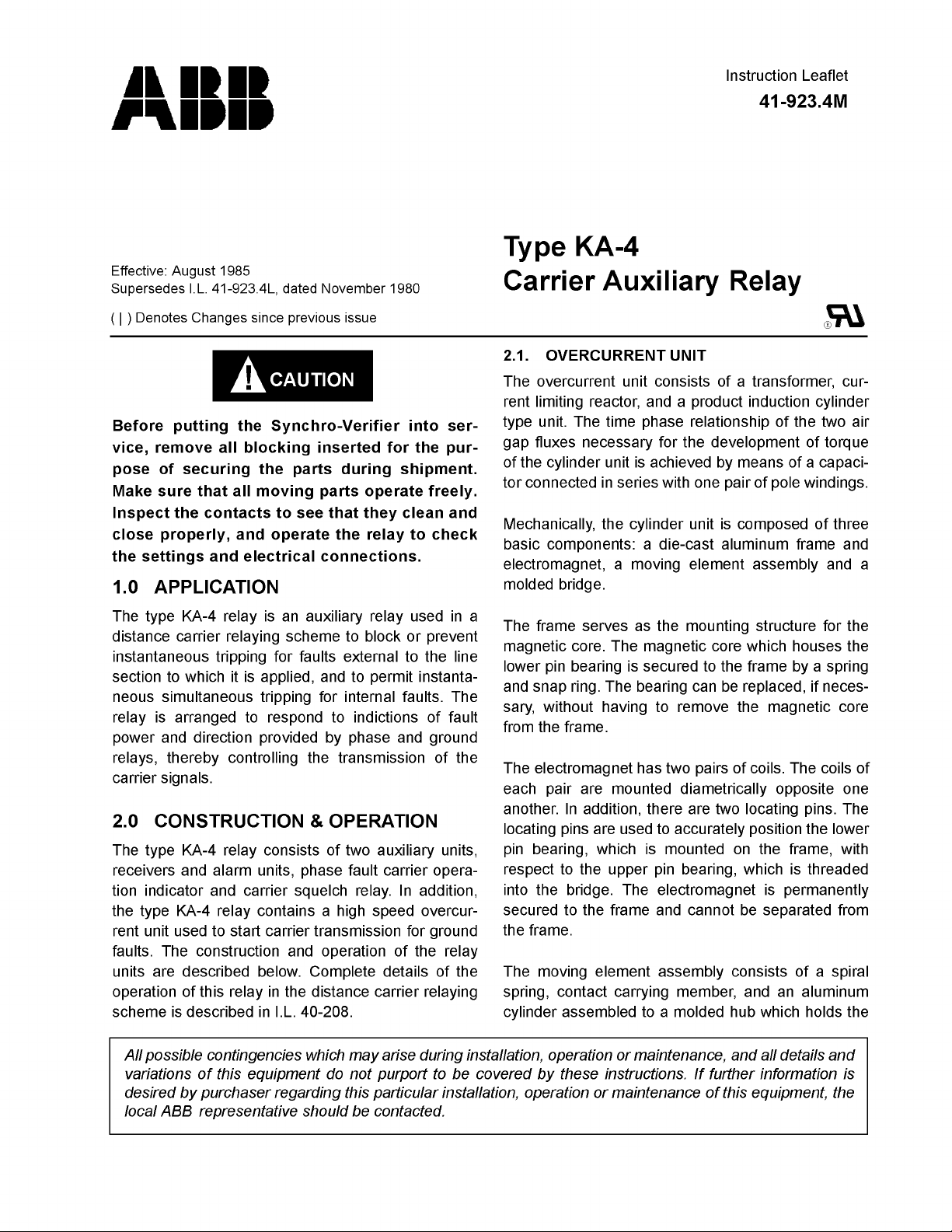
Figure 1. Type KA-4 Relay without case. (Front View)
2
Page 3
41-923.4M
Sub 3
629A389
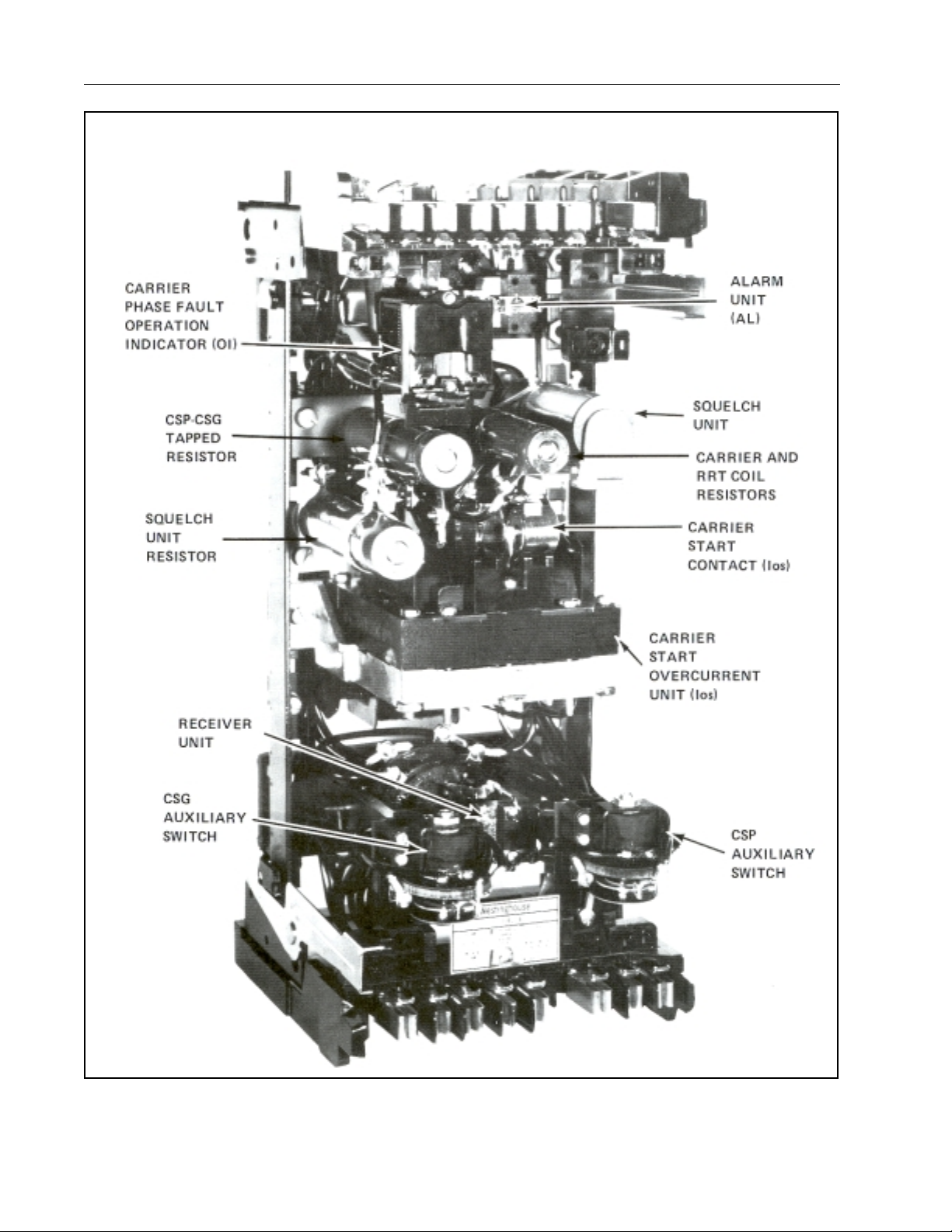
Figure 2.Internal Schematic of the Type KA-4 Relay for KR
Carrier Set.
Sub 9
629A476
Figure 3. Inter nal Schema tic of the Type KA-4 Re lay for TC
Carrier Set.
Sub 1
3491A17
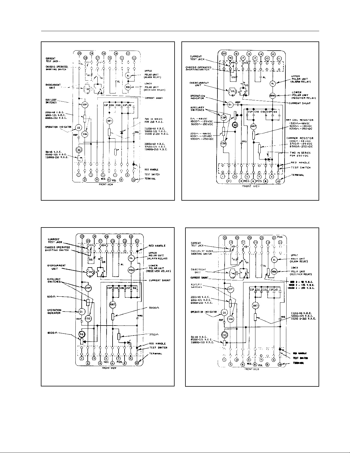
Figure 4.Internal Schematic of the Type KA-4 Relay with
Modified Carrier Stop to Terminal 11 for TC Carrier
Set.
Sub 1
349A16
Figure 5.Internal Schematic of the Type KA-4 Relay for the
TA-3 tones.
3
Page 4
41-923.4M
shaft. The shaft has remo va ble top and botto m jewel
bearings. The shaft rides between the bottom pin
bearing and the upper pin bearing with the cylinder
rotating in an air gap formed by the electromagnet
and the magnetic core.
The bridge is secured to the electromagnet and
frame by two mounti ng sc rews . In a ddi tio n t o h old in g
the upper pin bear ing, the bridge is used for mounting the adjustable stationary contact housing. The
stationary contact housing is held in position by a
spring type clamp. The spring adjuste r is located on
the underside of the bridge and is attached to the
moving contact arm by a spiral spring. The spring
adjuster is also held in place by a spring type clamp.
With the contacts closed, the el ectrical connec tion is
made through the stationary contact housing clamp,
to the moving contact, through the spiral spring out to
the spring adjuster clamp.
When the current in the overcurrent uni t exceeds the
pick-up value the contacts open, allowing positive
potential to be applied to the carrier transmitter.
A transformer and cu rrent limiting reactor is used i n
conjunction with the cylinder unit. The transformer
supplies one set of coils on the cylinder unit with voltage shifted by approximately 90° from the residual
current supplied directly to another set of coils. The
transformer and reactor are of the saturating type
which limits energy to the cylinder unit and reduces
the burden on the transmission line CT.
2.2. AUXILIARY UNITS
These are two solenoid- type cont actor switches designated as CSP and CSG. The plunger of the contactor switch has a circular conduc ting disc mou nted on
its lower end and as the pl unger travels upwar d, the
disc bridges three silver stationary contacts. The
CSP switch is ener gized by the operati on of t he sec ond zone or KD-10 distance relay, and the CSG
switch, by the operation of the directi onal and overcurrent units of the KRD-4 ground relay. The contacts
of the two switches are connected in parallel as
shown in the internal schematic. The operation of
either of these switches conn ects the carrier control
circuit to negative to stop carrier, and energizes the
RRT operating coil of the receiver relay unit.
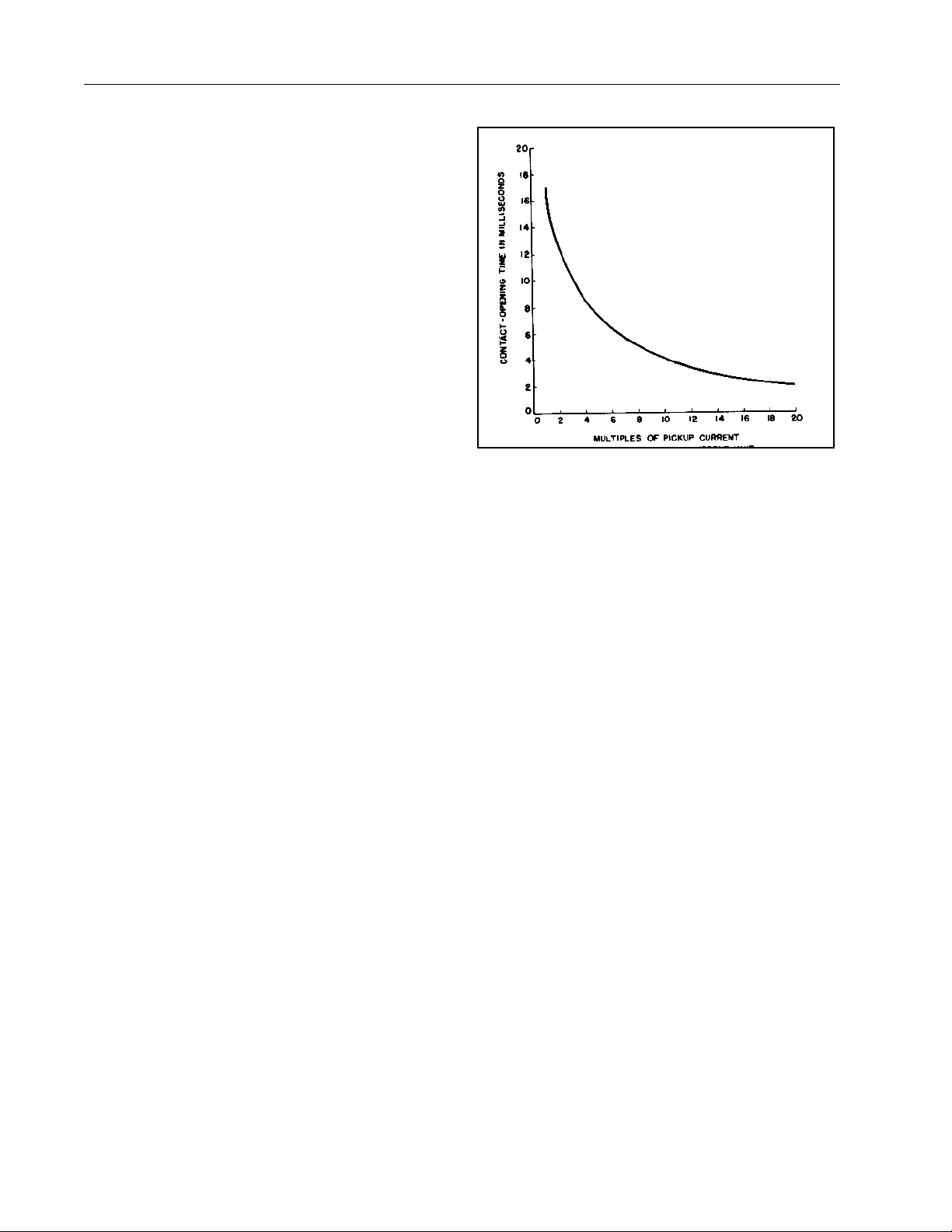
Figure 6.Typical Time Characteristics of c arrier start over-
current unit of the type KA-4 Relay.
2.3. RECEIVER UNIT
The receiver unit consists of an armature and contacts mounted on a leaf spring supporte d symmetrically within a magnet frame. The armature rides in
the front air-gap of the fr ame with the contacts projecting outside. The poles of a permanent magnet
clamp directly to each side of the frame. Two adjustable shunts are located across the rear air-gaps.
These change the reluctance of the magnetic path as
shown in Figure 7 so as to force some of the flux thru
the moving armature which is fastened to the fram e
midway between the two rear air gaps. Flux in the
armature polarizes it and creates a magnetic bias,
causing it to move towards either the left or right,
depending upon the adjustment.
Tw o st ati ona ry c onta ct sc re ws ar e m ount ed t o t he l eft
(front view) of the moving contact assembly and
adjusted for normally open contac ts. These co ntacts
are designated, RRP and RRG, and are connected in
the phase and ground trip circuit respecti vely. These
contacts are operate d by two concentric coils, RRT
and RRH, which are placed around the armature and
within the magnetic fra me. RRT is the operating coil
and receives its en ergy from the local battery when
either CSP or CSG is clo se d. R R H is th e h o ld ing c oil
and receives its en ergy from the carrier transmitted
either from the local tra nsmi tter or th e o ne a t th e en d
of the line section. These two coils are connect ed in
oppose each other with the operating coil, RRT oper-
4
Page 5
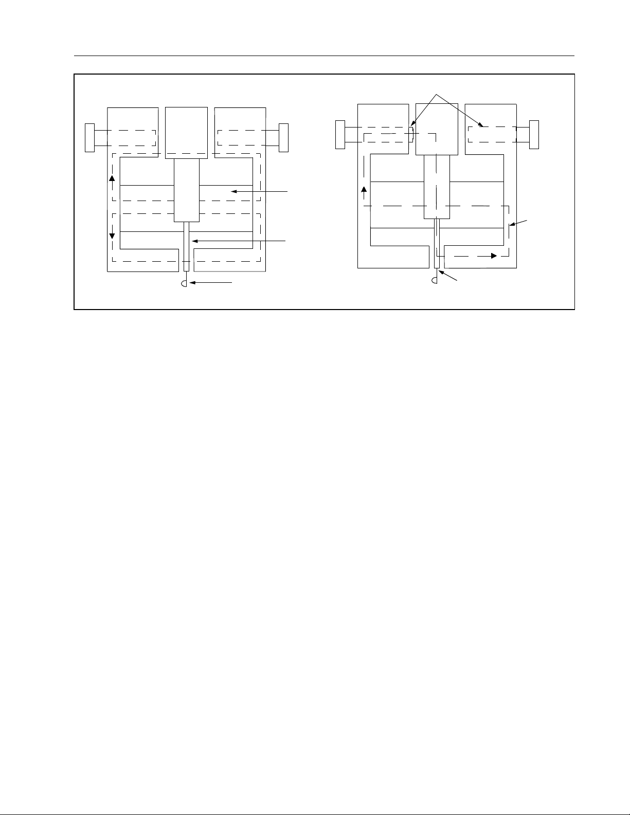
Shunt
41-923.4M
N
S
N
BALANCED AIR GAPS UNBALANCED AIR GAPS
S
Moving Contact
Figure 7. Permanent Magnet Flux Paths of Receiver and Alarm Units
Permanent
Magnet
Armature
ating to close the RRP and RRG contacts and trip;
and the holding co il, R RH to h old t he RRP and RRG
contacts open and block tripping. The restraining
torque of the RRH coil is sufficient to overcome th e
operating torque of the RRT coil. Consequently, RRP
and RRG contacts cannot c lose as long as RRH is
energized.
2.4. ALARM UNIT
The alarm unit is similar in construction to the
receiver unit except that it is energized by a single
coil and opera tes a singl e set of c ontac ts. T he c oil is
energized by the received carrier to close its contacts
and give an alarm. This unit has a higher pick-up
than that of the receiver unit in order to obtain a
direct check on the sensi tivity of the car rier transmitter-receiver. The failure of the alarm unit to pick-up
when carrier is started indicates insufficient output
from the transmitter receivers.
2.5. SQUELCH UNIT
The function of the squelch unit is to hold of the carrier for a period o f 15 0 m il lise co nds af ter th e B r eaker
“a” contact opens. This is to insure that all other ter minals of the line are tripp ed before allowing carrier
to be transmitted for any functions.
The squelch unit is a telephone type unit of slow
release type.
N
S
N
S
N
Additional
Flux Path
183A062
In these relays, an electromagnet attracts a right
angle iron bracket which in turn operates one normally open contact. The sl ow release is obtained by
a copper slug locat ed at the end opposite from the
armature. When the coil beco mes deenergized, the
change in flux through the slug results in an e lectromotive force and associated current in it. This current
produces a flux whic h aids the main flux and d elays
the release of the arm ature. When the coil is energized, the operation of the relay is not appreciably
delayed because the armature is operated by flux not
linking the slug.
2.6. OPERATION INDICATOR
The operation indicator gives a visual indication of a
carrier tripping op eration for phase faul ts by the distance relay through the RRP contac ts. For a groun d
fault carrier relaying ope ration, the indi cating conta ctor switch (ICS) located in the ground relay will drop a
target.
3.0 CHARACTERISTICS
The characteristics of the various elements of the
relays are as follows:
The pick-up and o perating values of thes e units are
given under “Adjustments and Maintenance”.
The time characteristic of the overcurrent unit is
5
Page 6

41-923.4M
For Use With KR-Set
CSP or CSG Coil
CSP & CSG Tapped Resistor
Carrier Resistor
RRT Operating Coil
RRT Coil Resistor
RRH Holding Coil
AL-Alarm Coil
Operation Indicator (1 amp.)
Squelch Unit Coil
Squelch Unit Adj. Resistor
For Use With TC-Set
CSP or CSG Coil
CSP & CSG Tapped Resistor
Carrier Resistor
RRT Operating Coil
RRT Coil Resistor
RRH Holding Coil
AL-Alarm Coil
Operation Indicator (1 amp.)
Squelch Unit Coil
Squelch Unit Adj. Resistor
For Use With TA-3 Tones
CSP or CSG Coil
CSP & CSG Tapped Resistor
Carrier Resistor
RRT Operating Coil
RRT Coil Resistor
RRH Holding Coil
AL-Alarm Coil
Operation Indicator (1 amp.)
Squelch Unit Coil
Squelch Unit Adj. Resistor
48V
Avg.
Ohms
27
200
2000
1100
1320
1700
500
0.1
3300
27
200
1000
1100
1320
20
0.1
3300
27
200
200
1100
1320
1700
500
0.1
3300
125
Avg.
Ohms
600
3750
1100
5000
1700
500
3300
-
8500
27
0.1
250
Avg.
Ohms
435
6000
19000
1100
11200
1700
500
0.1
3300
1500
the rear mounting stud or studs for projec tion mounting. Either a mounting stud or the mounting screws
may be utilized for grounding the relay. The electrical
connections may be made directly to the terminals by
means of screws for steel panel mounting or to the
terminal studs furnished with the rela y for thick panel
mounting. The terminal studs may be easily removed
or inserted by lock ing two nuts on the st ud and then
turning the proper nut with a wrench.
The carrier relaying schematic (supplied with the carrier order) should be consulted for details of the
external connections of these relays.
27
600
3750
1100
5000
4
20
4
0.1
3300
-
8500
45
6000
1100
11200
20
0.1
3300
15000
6.0 ADJUSTMENTS & MAINTENANCE
-
The proper adjustments to insure correct operation of
this relay have been made at the factory. Upon
4
receipt of the relay, no customer adjustments, other
than those covered under “SETTINGS”, should be
required.
6.1. ACCEPTANCE CHECK
27
600
4000
1100
5000
1700
500
0.1
3300
-
8500
435
6000
10600
1100
11200
1700
500
0.1
3300
15000
The following check is recommended to insure that
the relay is in proper working order.
6.1.1. Overcurrent Unit
Pass 0.5 amperes of altered current through relay
terminals 16 and 17, the contact should pickup within
.475 and .525 amp.
shown in figure 6.
The pick-up value of the overcurrent unit can be
changed from the factory adjusted value of 0.5
amperes to any value up to 1 amp. by increasing
spring restraint.
4.0 SETTINGS
There are not settings to be made
5.0 INSTALLATION
The relays should be mounted on switchbo ard panels or their equivalent in a location free from dirt,
moisture, excessive vibration, and heat. Mount the
relay vertically by means of the four mounting holes
on the flange for semi-flus h mou nting or by mea ns of
6
6.1.2. Auxiliary Units (CSP and CGS)
Each contactor switch has a section of a tapped
resistor in series with it, and will pick up positively
when rated control voltage is applied across the coil
and its section of the resistor.
These units should o per at e a t 24 v olts f or the 48 -vol t
relay, 60 volts for the 125-volt relay, and 120 volts for
250-volt relay. These units have an interm ittent rating, and should not be energized for more than a few
seconds.
6.1.3. Operation Indicator (OI)
With the polar unit contacts closed, apply direct cur rent to the operation indicator relay terminals. The
operation indicator should pick-up a nd drop the indicator target between 1 ampere and 1.2 amperes dc.
Page 7

41-923.4M
6.1.4. Squelch Unit (SQ)
Apply rated dc voltage to relay terminals that will
energize the squelch unit and note contact operation.
6.1.5. Blocking Zener Diode
Apply rated dc voltage in series with 10,000 ohm
resistors across te rminal s 8 a nd 9 wi th pos itiv e on 9 ,
the current leakage fl ow should not exceed .25 mA.
Reserve polarity of the applied voltage; the current
flow should be equ al to the applied voltage divide d
by the series resistance.
6.2. FOR RELAYS TO BE USED WITH
TC-TYPE CARRIER
6.2.1. Receiver Unit
Connect a jumper between the middle and left-hand
contact connection of the CS G or CSP switch. The
CSG switch is locate d on the left-hand pe destal and
CSP is located on the right-hand pedestal on the
relay (front view). Apply rated voltage across the
RRT coil and the RRT coil resistor, observing polarity
as shown in the internal schematic. The armature
should move to the left.
To the holding coil (RRH) relay terminals, apply direct
current observing pol arity. Increase the current until
the armature moves to the right.
The armature should move to the right at approximately 60 mA. Now reduce the current and the armature should move to the left at approximately 40 mA.
6.2.2. Alarm Unit (AL)
Connect direct curren t to the alarm unit relay terminals. Increase the cu rrent until the contacts p ick-up.
The contacts should pick up at approximately 80 mA.
Now reduce the current and the contacts should
open at 40 to 60 mA.
6.3. FOR RELAYS TO BE USED WITH
TYPE KR CARRIER OR TA-3 TONES
6.3.1. Receiver Unit
Connect a jumper between the middle and left-hand
contact connection of the CSG or CSP switch.
CSG switch is locate d on the left-hand pe destal and
CSP is located on the right-hand pedestal on the
relay (front view). Apply rated voltage across the
RRT coil and the RRT coil resistor, observing polarity
as shown in the internal schematic. The armature
should move to the left.
To the holding coil (RRH) relay terminals, apply direct
current observing correct polarity. Increase the current until the armature mov es to the right. The armature should move t o the r ight at a pprox imately 6 mA .
Now reduce the current and the armature should
move to the left at approximately 4 mA.
6.3.2. Alarm Unit (AL)
Connect direct curren t to the alarm unit relay terminals. Increase the curren t until the contacts pickup.
The contacts should pick up at approximately 8 mA.
Now reduce the current and the contacts should
open at 4 to 6 mA.
7.0 ROUTINE MAINTENANCE
All relays should be inspected periodically and the
operation should be checked at least once every
year or at such other tim e intervals as may be dictated by experience to be suitable to the particular
application.
All contacts should be periodically cleaned. A contact
burnisher Style # 182A836H01 i s recommended for
this purpose.
ing contacts is not recommended
danger of embedding small particles in the face of
the soft silver and thus impairing the contact.
7.1. CALIBRATION
Use the following procedure for calibrating the relay if
the relay has been taken apart for repairs or the
adjustments have been disturbed. This procedure
should not be used unless it is apparent that the relay
is not in proper working order. (See “Acceptance
Check”).
7.1.1. Overcurrent Unit
The upper bearing screw should be screwed down
until there is appr oximately 1/6 4” clearanc e between
it and the top of the shaft bearing. Securel y lock in
position with the lock nut. T he lower bearing po sition
is fixed and cannot be adjusted.
The use of abrasive mater ial for clean-
, because of the
7
Page 8

41-923.4M
With the moving contact in the normally closed position, i.e., against the right side of the bridg e, screw i n
the stationary conta ct until both contacts just close .
Then screw in the stationary contact a pproximately
one-quarter turn farther to provide the correct
amount of follow for KR & TC type carrier, one-half
turn for TA-3 tones.
The clamp holding the stationary contact housing
need not be loosened for the adjustment since the
clamp utilizes a spring- type action i n holding the s tationary contact in position.
The sensitivity adjustment is made by varying the
tension of the spiral spring attached to the moving
element assembly. The spring is adjusted by pl acing
a screwdriver or simila r tool into one of the notches
located on the periphery of the spring adjuster and
rotating it. The spring adjuster is located on the
underside of the bridge and is held in place by a
spring type clamp that d oes no t have to be lo osene d
prior to making the necessary adjustments.
Pass 0.5 amp of ac t hrough relay terminals 16 and
17. Adjust the spring until the contact just opens. In a
similar manner the pick- up value can be adjusted for
any value between .5 and 1.0 amp.
250-volt relay. These units have an interm ittent rating, and should not be energized for more than a few
seconds.
7.1.3. Squelch Unit
Check operation with timer. Adjust series resistor to
measure approximately 5000 ohms for 125 Vdc
relays and for 13000 ohms for 250 Vdc relay. With
armature closed, adjust the residual air gap to be
.002” – .003”. Contact gap should measure from
.020” to .035”. Check for dropout time betwe en .140
and .160 seconds. If ne cessary dropout ti me can be
adjusted by changing the residu al air gap. After final
adjustment the gap should be at lease .002”. The
pickup time should be below 16 milliseconds at -20%
rated dc voltage. If nec essary readjust series resistor.
7.1.4. Operation Indicator
The operation indicator s hould pickup and drop the
indicator target when the current is between 1 and
1.2 amperes dc.
Make sure that the target drops freel y when the uni t
operates.
7.1.2. Auxiliary Units (CSP and CSG)
The two contactor switches, CSP and CSG, have
adjustable plunger trave l. Adjust the stationary core
and the moving core of 1/64” when the switch is
picked up. This can be done by turning the relay
upside-down and screwing up the core screw of the
switch until the conta cts just separate. Then back off
the core screw approximately one turn and lock in
place. This prevents the moving core from striking
and sticking to th e stationary core beca use of residual magnetism. Adjust the contact clearance for
approximately 1/32” by me ans of the two small nuts
on either side of the Micarta disc.
Each contactor switch has a section of a tapped
resistor in series with it, and will pick up positively
when rated trip circuit voltages is applied across the
coil and its section of the resi stor.
The units should operate at 24 volts for the 48-volt
relay, 60 volts for the 125-volt rel ay and 120 v olts for
7.2. ZENER DIODE TEST
7.2.1. F orw ard Chara ct eri st ics
Pass 200 mA of dc current through terminals 8 and 9
with positive on terminal 8. Measure voltage drop
across terminal s 8 an d 9 with pos i tiv e o n 9 . T he vo ltage drop should not exceed 3.5 volts.
7.2.2. Reverse Characteristics –
Breakdown Voltage
The breakdown Voltage is determined by increas ing
voltage across terminal s 8 and 9 with positive on 9.
Place 10,000 ohm resistor in series with ammeter.
Increase voltage until current reads .25 mA. Measure
dc voltage across terminals 8 and 9. The voltage
should be between 16 0 a nd 2 40 v olts for 48 an d 12 5
Vdc rated relay s; and 320 to 480 volts for 250 Vdc
rated relays.
circuit.
DO NOT
exceed 3.0 mA current in the
8
Page 9

41-923.4M
7.3. FOR RELAY TO BE USED WITH
TC-TYPE CARRIER
7.3.1. Receiver Unit
Back off contact screws so that they do not make
contact. Screw magnetic shunts into the all- out position (5 or 6 screw threads showing.) The armature
should remain against whichever side it is pushed
with this adjustment.
Adjust the stationary contacts for a contact gap of
approximately .020” . This can be done by inse rting a
.010” steel thickness gage between the large rivet
head on the moving armature and the right-hand pole
face (a .010” travel of the rivet hea d is eq ual to .02 0”
travel of the moving contacts). Using an indicating
light in each contact circuit, adjust the upper and
lower stationary contacts to touch the moving contact
at the same time. W it h th e fe el er ga uge r emo ved th e
contact gap is 0.20” and the moving contacts close
simultaneously.
Connect a jumper between the middle and left-hand
contact connection of the CS G or CSP switch. The
CSG switch is located on the right-hand pedestal and
CSP is located on the right-hand pedestal of the
relay (front view). Apply rated voltage across the
RRT coil and the RRT coil resistor observing p olarity
as shown in the internal schematic diagram. The
armature should move to the left.
To the holding coil, RRH, a pply 100 to 200 milliamperes dc current observing correct polarity. The
armature should no w move to the right. Deenergiz e
both coils and see that the armature stays up against
the right-hand side.
Run both shunt screws all the way in, and the n back
out the left-hand shunt scr ew approximately 6 turns.
Back out the right-hand shun t screw appr oximate ly 9
turns.
Re-energize the operating coil with rated voltage and
the holding coil wi th 40 milliamperes dc. Adjust the
right-hand shunt scre w until the armature moves to
the left. If the armature moves to the left, at a value of
holding coil current gre ater tha n 40 millia mpere s, the
right-hand shunt sc rew sho uld be turned out to lower
this value to the correct 40 milliampere point.
Increase the holding coil curren t to 60 milliamperes
and adjust the left -hand shunt screw unti l the armature resets, or moves to the right. If the armature
resets at a value of current less than 60 milliamperes, the left-hand shunt screw should be turned
out. This will increase the reset value of the armature
and provide for the correct 60 milliampere reset
value.
Minor adjustments of both shunt screws must be
made several times until the desire d oper ating poi nts
are obtained, since the adjustments of one shunt
screw affect the adjustment on the other shunt screw.
7.3.2. Alarm Unit
The contacts should close with 80 milliamperes dc
±
5% applied to the alarm coil. Adjust the contact
screws to obtain an .050” contact gap such tha t the
armature motion between the left and right-hand contacts is in the central part of the air gap betw een the
pole faces. Tighten the contact locking nuts. Approximate adjustments of the two magne tic shunt screws
are as follows:
Turn both shunt screws all the way i n. Th en back out
both shunt screws app roximately seven tu rns. Apply
80 milliamperes dc to the coil, observing correct
polarity, and screw in the left-hand shunt screw until
the armature moves to the right. If the armature
moves to the right at a value of current less than 80
milliamperes, screw the left -hand shunt out until the
armature moves to the right at 80 milliamperes.
Check the dropout poi nt by reducing the dc cu rrent.
The armature should move to the left between the
limits of 40 and 60 milliamperes. If it fai ls to do so,
adjust the right-hand shunt screw until it does. It will
then be necessary to recheck the pickup and dropout
points again and make any minor adjustmen ts to the
shunt screws that may be necessary until correct calibration is obtained.
In general, screwing in the left-hand shunt screw
reduces the pickup current of the relay. Screwing in
the right-hand shunt screw increases the dropout
current. This will in turn cause a change in the pickup
current, making necessary several slight readjustments of both shunt screws to obtain the desired calibration. The armature as finally calibrated should
pickup and dropout with a snappy action.
9
Page 10

41-923.4M
7.4. FOR RELAYS TO BE USED WITH
KR-TYPE CARRIER OR TA-3 TONES
7.4.1. Receiver Unit
Calibrate as outlined under TC Type Carrier. Apply
15 mA dc cu r re nt fo r po la ri t y check. Th e pi ck up v al ue
should be 4 milliamperes dc ( armature moves to left)
instead of 40 mA. T he calibration of re set (armature
moves to the right) should be done at 6 milliam peres
instead of 60 mA.
7.4.2. Alarm Unit
Calibrate as outlined under TC-type Carrier. Check
pick-up at 8 mA ±5% instead of 80 mA. Dropout
should be between 4 and 6 mA ins tead o f 40 an d 60
mA.
8.0 RENEWAL PARTS
Repair work can be done most satisfactorily at the
factory. However, interchangeable parts can be furnished to the custom ers who are equipped for doing
repair work. When ordering parts, always give the
complete nameplate data.
9.0 ENERGY REQUIREMENTS
9.1. CURRENT BURDEN AT 60 CYCLES
Power
Current
Amperes
0.5
5
20
40
60
†
Current lagging voltage
††
Current leading voltage.
9.2. RATING OF OVERCURRENT UNIT
Continuous rating 5 amperes. One second rating 100
amps.
Volt
Amperes
2.2
43
394
1240
2760
.
Factor
Angle
†
33°
†
70°
††
49°
39.2°
32.5°
††
††
10
Page 11

THIS P AGE LEFT BLANK
41-923.4M
11
Page 12

41-923.4M
12
Sub 4
5307D96
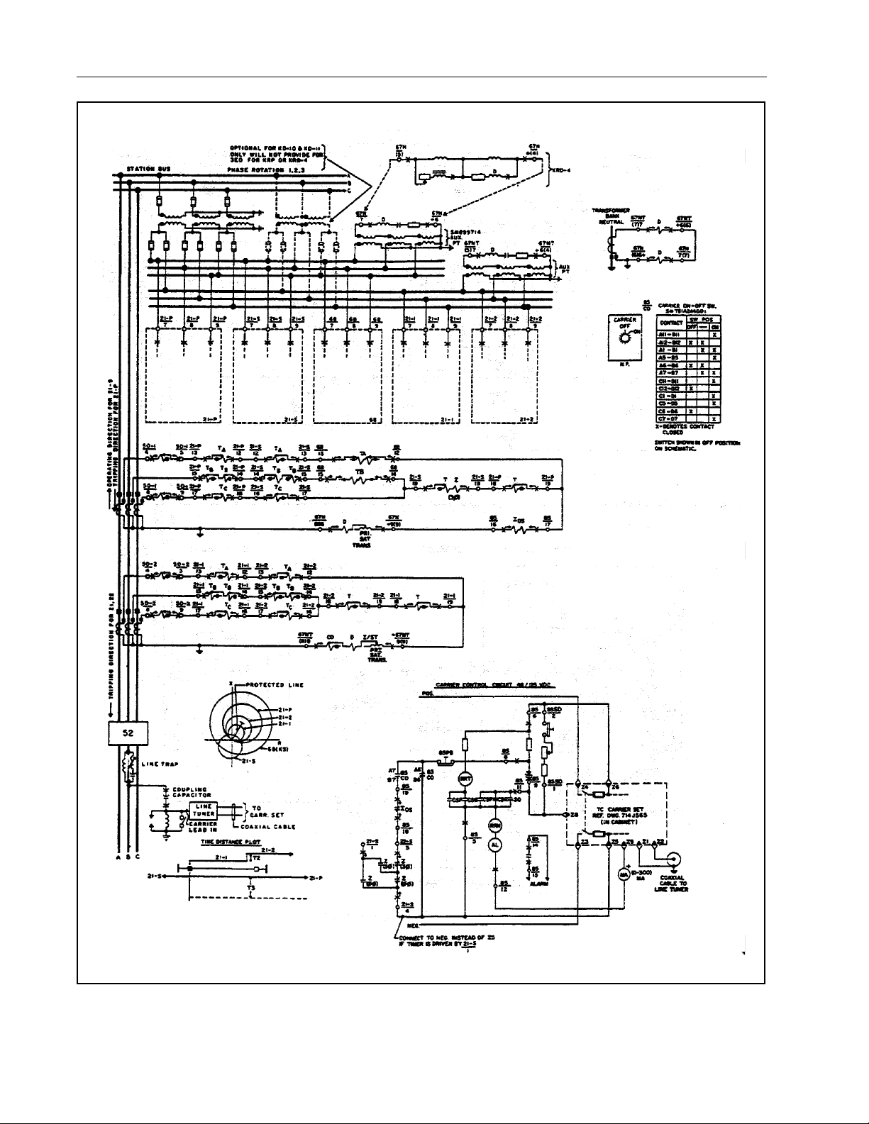
Figure 8. Typical External Schematic of a KA-4 Relay in a KD-4/TC Blocking System
Page 13

41-923.4M
Figure 8. Typical External Schematic of a KA-4 Relay in a KD-4/TC Blocking System
Sub 4
5307D96
13
Page 14
41-923.4M
14
Figure 9A. Typical External Schematic of a KA-4 Relay in a KD-10/TC Blocking System
Page 15

41-923.4M
Figure 9B. Typical External Schematic of a KA-4 Relay in a KD-10/TC Blocking System
15
Page 16

 Loading...