

Page 1
Options for ABB drives, converters and inverters
User’s manual
JPC-01 network communication adapter
English . . . . . . . . . . . . . . . . . . . . 3
3AUA0000072233 Rev A
Effective: 2012-06-26
2012 ABB Oy. All rights reserved.
Page 2

Page 3

JPC-01 User’s manual 3
JPC-01 User’s manual
About this manual
This manual introduces the installation and start-up of the JPC-01
network communication adapter module. This manual is intended
for the people who are responsible for installing, commissioning
and using a JPC-01 module with an ABB drive. The reader is
expected to have a basic knowledge of electrical fundamentals,
electrical wiring practices, the drive, and the use of the drive
control panel.
Safety instructions
WARNING! All electrical installation and maintenance
work on the drive should be carried out by qualified
electricians only.
The drive and adjoining equipment must be properly earthed.
Do not attempt any work on a powered drive. After switching off the
supply voltage, always allow the intermediate circuit capacitors to
discharge for 5 minutes before working on the drive, the motor or
the motor cable. It is good practice to check (with a voltage
indicating instrument) that the drive is in fact discharged before
beginning work.
These warnings are intended for all who work on the drive.
Ignoring the instructions can cause physical injury or death, or
damage the equipment.
For complete safety instructions see the drive manuals.
Page 4

4 JPC-01 User’s manual
Overview
The JPC-01 module is an RS232-to-RS485 converter with galvanic
isolation. It enables the use of a PC in a network configuration
(RS485) to communicate with ACSM1 drives.
The RS-232 side of the JPC-01 module acts as an interface
towards the JCU control unit via the RJ45 panel connector. The
RS-232 side also supplies power to the JPC-01 module.
The RS-485 side of the JPC-01 module acts as an interface
towards the PC tool network. It consists of a 4-pin removable
screw type connector and a termination switch for active
termination of the RS485 bus. Termination is required only at bus
ends.
The JPC-01 supports:
• daisy chained connection of the network cable,
• transmission speeds from 9.6 kbit/s in multiples up to
57.6 kbit/s,
• a maximum network length of 100 m, and maximum node-to-
node length of 30 m,
• a maximum of 31 drives in one network.
The recommended PC adapter is MOXA UPort 1150i USB to 1 port
RS-232/422/485 adapter with isolation.
Page 5
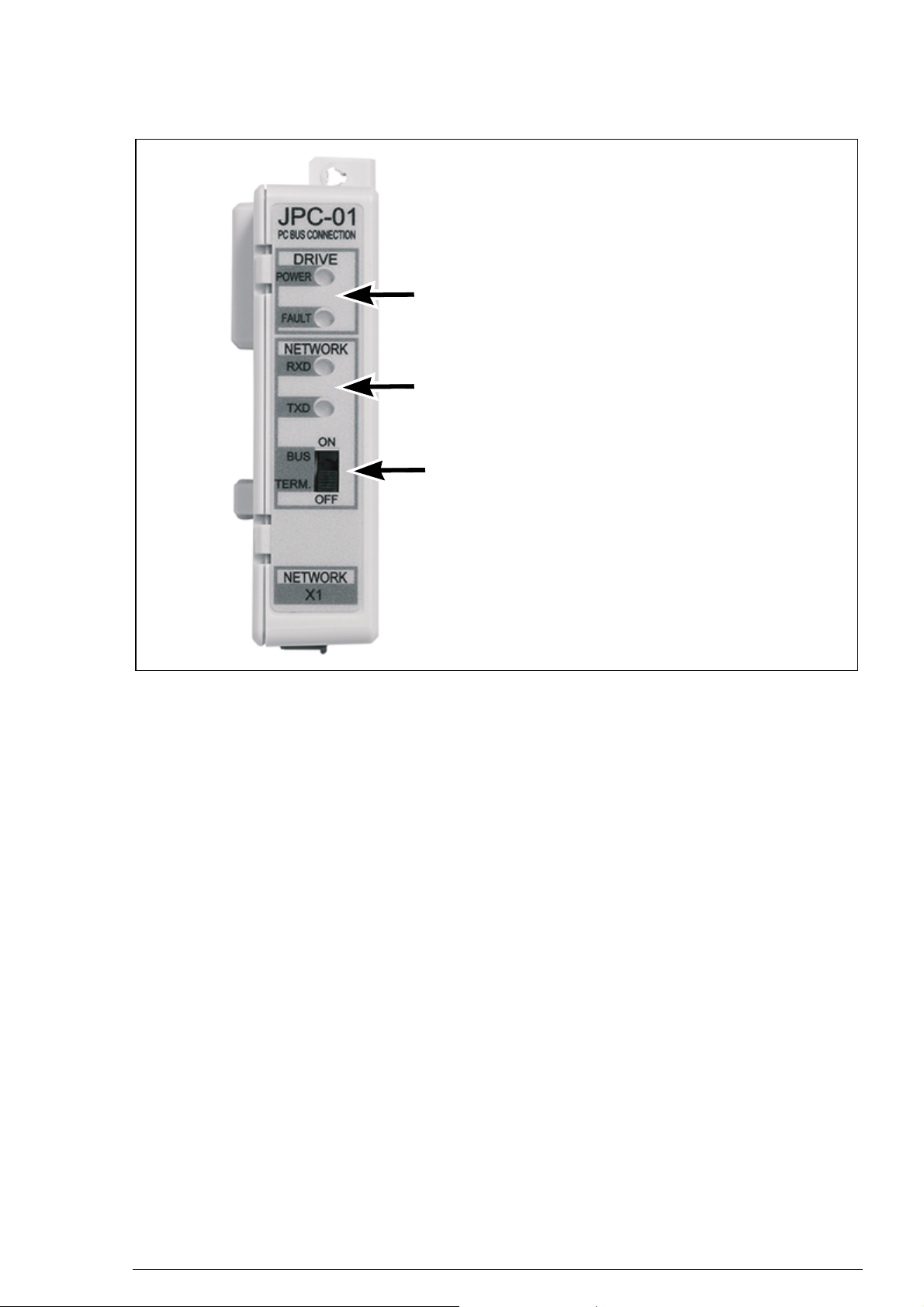
Layout
Drive status indication LEDs (see section
LED indications on page 11).
RS-485 network status indication LEDs
(see section LED indications on page 11).
Bus termination selection switch
ON – Bus termination on
OFF – Bus termination off
JPC-01 User’s manual 5
Page 6
6 JPC-01 User’s manual
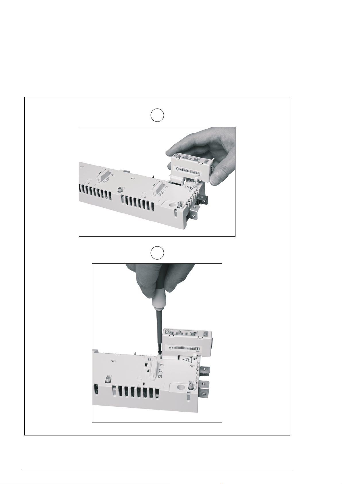
1
2
Installation
1. Insert the JPC-01 module to the panel port of the JCU control
unit.
2. Fasten the screw.
Page 7

JPC-01 User’s manual 7
JPC-01 #1 JPC-01 #2 JPC-01 #n
1234
SHLDB+A-
GND
1234
SHLDB+A-
GND
1234
SHLDB+A-
GND
RS-232
RS-485
PC
…
max. 31 nodes
RS-485 cabling is done in the bottom direction (parallel with the I/O
cabling). For details, see appropriate ACSM1 hardware manual.
The connection terminals are DATA-, DATA+, BGND, SH.
Page 8

8 JPC-01 User’s manual
Quick start-up with DriveStudio v1.6
In DriveStudio v1.6, parameter group 55 COMMUNICATION TOOL
is used for configuring the network. DriveStudio can be used for
setting the parameters of one drive at a time and for monitoring the
signals of several drives simultaneously.
With parameter 55.01 MDB STATION ID, the node number is set in
the range of 1…247. With parameter 55.02 MDB BAUD RATE, the
communication speed is defined. With the default setting, (0) Auto,
the initial speed at power-up or after communication loss is
9600 bit/s. Note: Parameter 55.02 must be set to (0) Auto when
using a control panel.
1. Ensure that your PC is connected to one of the drives at a time
when configuring the RS-485 network. There are three ways to
do the connection:
• Point-to-point connection from the PC directly to one of the
JCUs
• Each JPC-01 connected to its JCU but only one JCU
powered (network connection)
• Only one JPC-01 in the RS-485 chain connected to a JCU
(remaining JPC-01s detached from the JCU).
2. Set parameter 55.01 MDB STATION ID to a value between 1
and 31.
Page 9

JPC-01 User’s manual 9
3. Set parameter 55.02 MDB BAUD RATE to the value of
57600 bit/s.
4. Repeat the procedure (steps 1…3) for the remaining drives;
connect the drives to the PC tool network one by one.
Note: The new settings for parameters 55.01 and 55.02 become
valid when the communication is interrupted either by restarting
DriveStudio, removing the communication cable or restarting the
JCU.
5. After having configured group 55 for each drive, select OPC
Server Settings from the Edit menu.
6. Launch the ABBCOMSAP server configuration window from
the taskbar.
• COM Port shows all currently available COM ports.
• Default (247) defines the node number that DriveStudio
uses when it communicates with the drives. With the box
ticked, the node number used is 247 which represents a
broadcast message to each drive (no response). With the
box unticked, the node number range during the scan
Page 10

10 JPC-01 User’s manual
8 9 10 118
cycle is defined by the Start node and End node fields. By
limiting the range the scan takes less time to finish.
• Default Speeds defines the baud rate used during the
node scan cycle and normal communication. With the box
ticked, the node scan is performed at 9600 bit/s; the speed
is then increased to the maximum. With the box unticked,
the speeds are defined by the Scan Speed and Comm
Speed fields respectively.
• Leave the Default (247) and Default Speeds boxes ticked
(default) during the point-to-point connection (steps 1…3).
7. Check the COM port used from DriveStudio.
8. Untick the boxes Default (247) and Default Speeds in the
COM port used.
9. Change the setting of End node according to the maximum
number of nodes.
10. Change the setting of Scan Speed to 57600 bit/s.
11. Leave the setting of Comm Speed on 57600 bit/s.
12. Click OK.
13. Connect all drives to the RS-485 network.
14. Scan the network by selecting View – Refresh or restarting
DriveStudio.
15. DriveStudio will show all drives connected to the network.
Page 11

JPC-01 User’s manual 11
Fault tracing
LED indications
Indication of drive status
Name Color Meaning
POWER Green Drive powered
FAULT Red Drive faulted
Indication of network (RS-485) status
Name Color Meaning
RXD Green Receive data
TXD Green Transmit data
Technical data
Operating voltage: 24 V DC ± 10% (supplied by the drive)
Power consumption: max 1.2 W
Ambient conditions
Operating temperature: 0…60 °C
Storage temperature: -40…+70 °C
Max. relative humidity: 95% (non-condensing)
Lifetime: 100 000 h
Standards
Complies with EMC standard EN 61800-3:2004.
PCB materials are UL recognized.
All materials must be RoHS compatible.
Page 12

12 JPC-01 User’s manual
Dimensions
Page 13

Further information
Product and service inquiries
Address any inquiries about the product to your local ABB
representative, quoting the type designation and serial number of
the unit in question. A listing of ABB sales, support and service
contacts can be found by navigating to www.abb.com/drives
selecting Sales, Support and Service network.
and
Product training
For information on ABB product training, navigate to
www.abb.com/drives
and select Training courses.
Providing feedback on ABB Drives manuals
Your comments on our manuals are welcome. Go to
www.abb.com/drives
feedback form (LV AC drives).
and select Document Library – Manuals
Document library on the Internet
You can find manuals and other product documents in PDF format
on the Internet. Go to www.abb.com/drives
Library. You can browse the library or enter selection criteria, for
example a document code, in the search field.
and select Document
Page 14

Contact us
www.abb.com/drives
www.abb.com/drivespartners
3AUA0000072233 Rev A (EN) 2012-06-26
 Loading...