

Page 1
EN 1
—
SAF ET Y P R OD UC T S
GKey – Safety Lock
Excerpts from the original instructions
General description
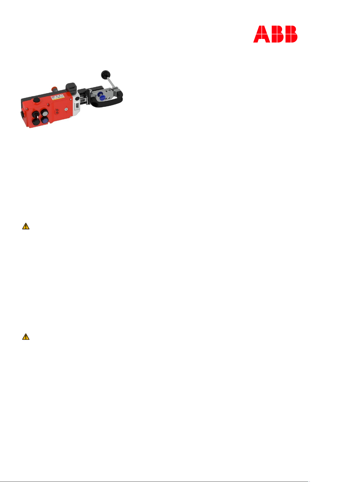
GKey safety lock incorporate an RFID interlock switch and is designed to fit to the leading edge of machine guard doors to provide robust
guard locking and double tamper resistant interlock mechanism. It is designed to provide position interlock detection for moving guards
and will keep the guard locked until a voltage is applied to the switch solenoid.
GKey safety lock will hold guards closed up to 3000 N. It can be used in conjunction with delay timers to provide the solenoid energize
signal only after a pre-determined time has run down. GKey housing can incorporate positions for mounting of standard 22 mm
pushbuttons, switches or lamps to facilitate machine request functions and diagnostics all in one housing. These pilot devices are ordered
separately.
Installation
Installation of all GKey safety locks must be in accordance with a risk assessment for the individual application.
Installation shall only be carried out by competent personnel and in accordance with these instructions.
Use 16-28 AWG copper conductors. Terminal torque 0.7 Nm.
Caution!
Make sure the Manual unlock function selector is in “Locked” position before putting the cover back on.
Mount the GKey rigidly to the fixed frame of the guard or machine. Fit the actuator to the moving part of the guard and align it to the
switch entry aperture.
1. M5 mounting bolts must be used to fix the switch and actuator mounting.
The tightening torque to ensure reliable fixing is 4.0 Nm.
Tightening torque for the lid screws and cable glands must be 1.5 Nm to ensure the IP seal.
Always fit the aperture plug to the unused entry aperture to prevent debris entering the switch mechanism.
2. Always fit a mechanical stop to the guard to prevent damage to the switch.
Ensure correct alignment of actuator and handle with front apertures of the switch and guide. Use alignment guides to ensure that the
actuator enters the switch without interfering with the sides of the aperture.
Do not mount adjacent switches or actuators closer than 100 mm.
3. The manual unlock function is achieved by using a tool and is to be used in exceptional circumstances. The release can be protected by
use of a tamper coating to prevent unintended operation. If operated, this tamper protection is damaged and must be restored to
ensure protection.
4. When fitting a handle, ensure that M6 mounting bolts are used to fix the mounting plate. The tightening torque to ensure reliable fixing
is 4.0 Nm.
Warning!
When cutting the panel to allow the movement of the rear handle:
• Consider the opening when calculating the safety distance
• Make sure that there are no remaining sharp cutting edges
Check after installation
After installation operation of all control circuits, the locking function and rear escape release functions shall be checked.
For applications with a run-down time after removing power, ensure that the correct timing allowance has been made before the solenoid
is energized.
[EN] The complete original instructions can be found at:
[DE] Die komplette Originalbetriebsanleitung ist zu finden unter:
[ES] La versión original de la instrucciones está disponible en:
[FR] La notice originale intégrale est disponible sur :
[IT] Le istruzioni originali complete si trovano qui:
[SV] Den kompletta bruksanvisningen i original finns på:
[ZH] 完整的原始说明可以在以下网址查阅:
www.abb.com/jokabsafety
Page 2
EN 2
Electrical connections
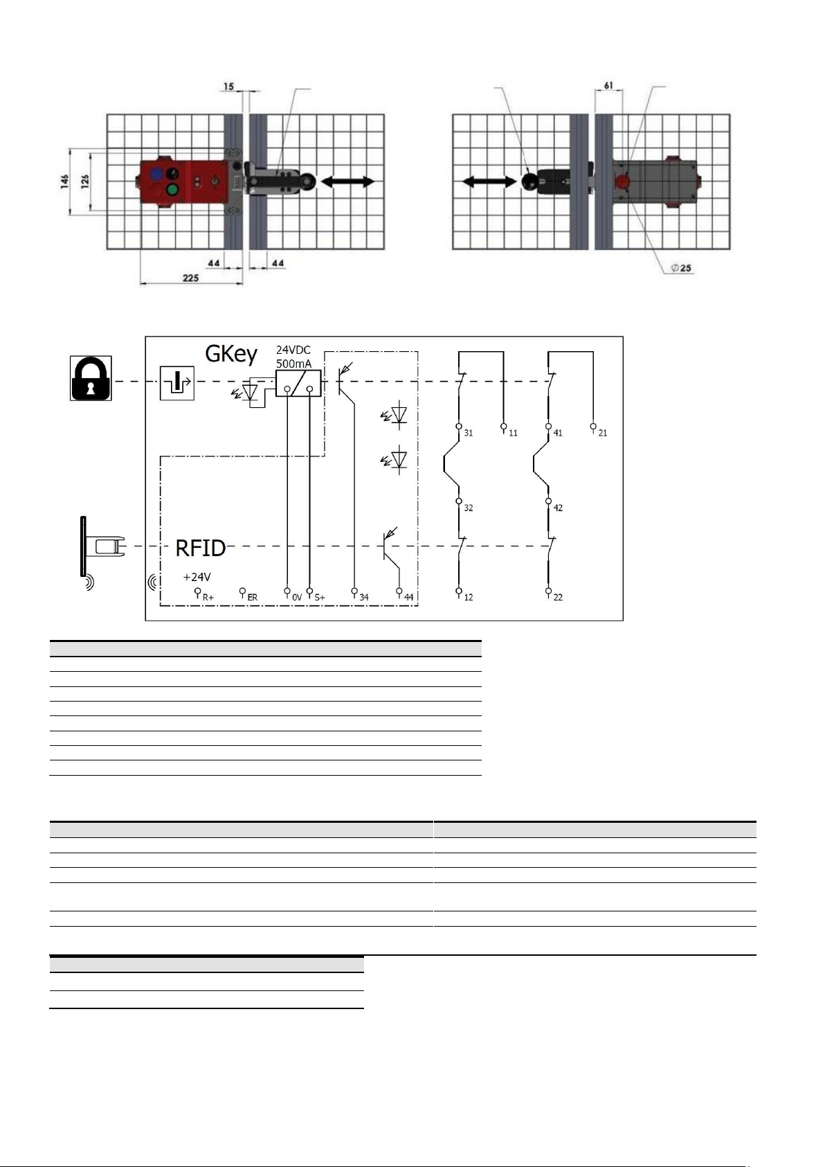
Terminal connections
0 V
Supply 0 V
R+
Supply +24 VDC
S+
Unlock signal (solenoid) +24 VDC in
11/12
Safety interlock and lock monitoring circuit
21/22
Safety interlock and lock monitoring circuit
44
Guard opened signal +24 VDC out
34
Guard unlocked signal +24 VDC out
ER
External Reset Signal
LED Diagnostics
There are two LED indicators on the GKey switch.
Safety lock state
LED 1 (Green/Yellow)
Comment
Guard Open
OFF Guard Closed + Locked
Steady green
Safety outputs ON
Guard Closed + Unlocked
Flashing green
Guard Closed + Misaligned/
Wrong actuator
Alternate flashing green/
yellow
Fault
Steady yellow
See Reset instructions (in complete original instructions)
Problem with reset procedure
Steady green and yellow
Make sure the RFID actuator is in contact with GKey (guard
closed) and cycle the power.
Solenoid state
LED 2 (Red)
Energized
ON
De-energized
OFF
Maintenance
Every month: Check correct operation of all circuits and the Lock function. If any part of the GKey product displays mechanical damage,
then remove and replace.
Every six months: Isolate power and remove cover. Check screw terminal tightness and check for signs of moisture ingress. Re-check
according to the installation instructions in this manual.
Lock closed
and locked
Red
Green
Yellow
Error
reset
Front
handle
Rear
handle
Escape release
button
Page 3
EN 3
Warning!
The safety functions and the mechanics shall be tested regularly.
Warning!
In case of breakdown or damage to the product, contact the nearest ABB Jokab Safety representative. Do not
try to repair the product yourself since it may accidentally cause permanent damage to the product, impairing
the safety of the device which in turn could lead to serious injury to personnel.
Manufacturer
Address
ABB AB, Jokab Safety
Varlabergsvägen 11
SE-434 39 Kungsbacka
Sweden
Technical data
Supply voltage
+24 VDC ±10 %
Power consumption
R+ 1.2 W (50 mA max.)
S+ 12 W (500 mA max.)
Safety circuits
+24 VDC, 200 mA max. switching
Auxiliary circuits (34 & 44)
+24 VDC, 200 mA max. output feed
Rated insulation voltage
500 VAC
Rated impulse withstand
1000 VAC
Holding force
Switch holding force (FZh)
F1 max. 3000 N
2307 N
Classification and coding level (EN ISO 14119)
Type 4 high
Actuator insertion distance for assured locking
5 mm
Sao (RFID)
10 mm
Sar (RFID)
20 mm
Operating frequency
1 Hz max.
Actuator entry minimum radius
175 mm
Body material
Die-cast metal aluminum alloy
Head material
Stainless steel
Mechanical actuator material
Stainless steel
Enclosure protection
IP65
Operating temperature
-25 °C to +40 °C
Mechanical life expectancy (B
10D
)
2.5 x 10⁶ cycles at 100 mA load
Vibration
IEC 60068-2-6, 10-55 Hz+1 Hz
Excursion: 0.35 mm, 1 octave/min
Safety / Harmonized standards
Conformity
European Machine Directive 2006/42/EC
EN 60947-5-3, EN ISO 13849-1, EN 62061,
EN ISO 14119, UL 508
EN ISO 13849-1
Performance level: PL e (If both channels are used in conjunction with a SIL3/PL e control
device)
Category 4, MTTF
d =
1100 a
Diagnostic coverage: DC = 99% (High)
EN 62061
(used as a subsystem)
Safety integrity level: SIL3
PFH (1/h) = 4.77E-10 (Corresponds to 4.8% of SIL3)
PFD = 4.77E-10 (Corresponds to 4.2% of SIL3)
Proof test interval T1 = 20 a
Operating assumptions
Days per year: dop = 365 d
Hours per day: hop = 24 h
Note: If the usage of the product differs from these assumptions (different load, operating frequency, etc.) the values must be
adjusted accordingly.
Certifications
cULus, TÜV Rheinland
Information for use in USA/Canada
Enclosure
Type 1
Maximum temperature
40 °C
Conductors
Use 16-28 AWG copper conductors (rated +90 °C)
Terminal torque
6 lb ins. (0.7 Nm)
Intended for same polarity use
Safety circuits (11-31 & 21-41)
A300 Pilot duty 240 V 3A
(PF 0.38 or greater tested for 6,000 cycles endurance)
Push button ratings (optional)
120 - 240 VAC, 1.5 - 1.0 A
24 - 125 VDC, 0.3 - 0.2 A
Use one polymeric conduit connection. Not suitable for connection to rigid metal conduit. (Earth bonding terminal inside enclosure
if required – use 16-12 AWG conductors)
Descriptions and examples show how the product works and can be used. It does not mean that it fulfills the requirements for all
types of machines and processes. The buyer/user is responsible for installing and using the product according to applicable
standards and regulations. We reserve the right to make changes to the product and the documentation without prior notice.
2TLC010049M0201_C
 Loading...