

Page 1

—
ABB MEASUREMENT & ANALYTICS |
CEMcaptain GAA610
Advanced emission gas monitoring system for marine
applications
—
GAA610
Introduction
GAA610
continuously monitoring SO2/CO2 emissions of
vessels.
Reducing maintenance hassles during ship
operation has been the guiding
development. An increased uptime is provided
with the GAA610
design as well as its innovative digital features
allowing for tailoring services to your needs.
It is proven for use on board by all major
classificatio
Annex IV requirements and NOx Technical Code
2008.
ABB has the right gas analyzer to allow vessels to
stay compliant with current and upcoming
regulations.
Additional Information
OPERATING INSTRUCTION | OI/GAA610-M -EN REV. B
-M
Measurement made easy
-M
-M is a multi-component analyzer system
Additional documentation on CEMcaptain GAA610-M
is available for download free of charge at
www.abb.com/analytical.
Alternatively simply scan this code:
principle for
-M by its robust and simple
n societies and complies with Marpol
Page 2

2 GAA610-M ADVANCED EMISSION GAS MONITORING SYSTEM | OI/GAA610-M-EN REV. B
Table of contents
1 Safety ........................................................................ 5
General information and instructions ................................. 5
Warnings .................................................................................. 5
Warranty provisions ............................................................... 5
Intended use ............................................................................ 6
Improper use ........................................................................... 6
Safety instructions ................................................................. 6
Requirements for safe operation .................................... 6
Personnel qualifications ................................................... 6
Special information and precautions ............................. 6
National regulations .......................................................... 6
Safety of the equipment and safe operation................. 6
Working with hazardous gases ........................................ 7
Protective lead connection ............................................... 7
Risks involved in opening the covers .............................. 7
When safe operation can no longer be assured ............ 7
Risks involved in opening the gas paths ........................ 7
Notes on data safety .............................................................. 7
Services and ports on the Ethernet interface ................ 7
Access authorizations ....................................................... 7
Manufacturer’s address ......................................................... 8
Service address ....................................................................... 8
2 Design and function ................................................. 9
Measuring principle ................................................................ 9
Device description .................................................................. 9
Type approvals ................................................................... 9
Measurement ranges ........................................................... 10
Inputs and outputs ............................................................... 10
Analog output .................................................................. 10
Digital output ................................................................... 10
System structure .................................................................. 11
System cabinet................................................................. 11
System schematic ............................................................ 12
Sample Gas Cooler SCC-C............................................... 13
Sample Gas Feed Unit SCC-F ......................................... 14
3 Product identification ............................................ 15
Name plate ............................................................................ 15
Plates and symbols .............................................................. 15
Scope of delivery .................................................................. 15
4 Transport and storage ............................................ 16
Safety instructions ............................................................... 16
Inspection .............................................................................. 16
Transporting the device ...................................................... 16
Transporting the analyzer cabinet ................................ 16
Unpacking the analyzer cabinet..................................... 16
Storing the device ................................................................ 17
Ambient conditions ......................................................... 17
Packaging .............................................................................. 17
Returning devices ................................................................. 17
5 Preparation for Installation ................................... 18
Safety instructions ...............................................................18
Installation – Overview .........................................................18
Requirements for the installation site ...............................18
Choosing the extraction point .......................................18
Wall tube installation .......................................................18
Short gas paths ................................................................19
Protection from adverse ambient conditions ..............19
Installation indoors ..........................................................19
Dimensions and space requirement ..............................19
Installation site stability..................................................19
Climatic Conditions .........................................................19
Backpurging Unit ................................................................. 20
Design of the back-purging unit ................................... 20
Distance to sampling probe .......................................... 20
Protection from adverse ambient conditions ............. 20
Instrument air supply ..................................................... 20
Power supply ........................................................................ 20
Sample gas inlet conditions ............................................... 20
Dimensions ............................................................................ 21
Analyzer cabinet ............................................................... 21
Type 40 probe tube and filter unit ................................ 22
Backpurging Unit ............................................................ 23
Material required for installation ....................................... 24
Gas sampling ........................................................................ 24
Gas lines............................................................................ 24
Mounting material........................................................... 24
Cable specification ......................................................... 24
6 Installation ............................................................... 25
Probe tube and filter unit installation ............................... 25
Before the installation .................................................... 25
Filter unit overview ......................................................... 25
Installation ....................................................................... 26
Sample gas line installation .................................................27
Installing the sample gas line .........................................27
Fundamentals for laying the sample gas line ..............27
Procedures for laying the sample gas line ................... 28
Permissible values for laying the sample gas line ...... 29
Back-purging unit installation............................................ 29
Before the installation .................................................... 29
Installation site ................................................................ 29
Connecting the compressed-air tubes ........................ 29
Analyzer cabinet installation .............................................. 30
Transporting the analyzer cabinet................................ 30
Unpacking the analyzer cabinet .................................... 30
Mounting the analyzer cabinet ...................................... 30
Connecting the condensate water drain of the cabinet air
conditioner............................................................................ 30
Page 3

GAA610-M ADVANCED EMISSION GAS MONITORING SYSTEM | OI/GAA610-M-EN REV. B 3
7 Gas connections ...................................................... 31
Position and design of the gas connections .................... 31
Connecting the gas lines ..................................................... 32
Connecting the heated sample gas line ....................... 32
Calibration gas ................................................................. 32
Connecting the condensate bottle ............................... 32
Connecting the sample gas outlet ................................ 32
8 Electrical connections ............................................. 33
Safety instructions ............................................................... 33
Protective lead connection ............................................. 33
Notes ...................................................................................... 33
Cable specification ............................................................... 33
Cable glands ..........................................................................34
Terminal assignment – Analyzer cabinet........................... 35
Electrical Data .................................................................. 37
Connecting the electrical leads ..................................... 38
Connecting the signal leads ........................................... 38
Connecting the power supply ........................................ 38
Terminal assignment – Sample gas probe ........................ 39
Electrical data ................................................................... 39
Electrical connection ....................................................... 39
Digital communication ........................................................ 39
Modbus® communication ............................................... 39
Ethernet communication ................................................ 39
9 Gas sampling with automatic back-purging ....... 40
General .................................................................................. 40
Filter plugging ...................................................................... 40
Pump suction increase ................................................... 40
Filter cleaning .................................................................. 40
Components for back-purging .......................................... 40
Control of the back-purging procedure ...................... 40
Start of the back-purging procedure ............................... 40
Start controlled by time ................................................. 40
Start controlled by event ............................................... 40
Manually controlled start ............................................... 40
Filter unit backpurging sequence .................................. 41
Switch over ....................................................................... 41
Cycle time .............................................................................. 42
Cycle time duration ......................................................... 42
Cycle time factory setting .............................................. 42
Optimum cycle time setting........................................... 42
Cycle time minimum value .............................................. 42
Event-controlled start of the back-purging procedure
by filter plugging ............................................................. 42
Adjustment of the cycle time ......................................... 42
Post-purge time .................................................................... 42
Post-purge time duration ............................................... 42
Guide for the post-purge time ....................................... 42
Adjustment of the post-purge time .............................. 42
10 Commissioning and operation .............................. 43
Safety instructions .............................................................. 43
When safe operation can no longer be assured ......... 43
Transportation restraints removal .................................... 43
Sample Gas Feed Unit SCC-F ......................................... 43
Sample Gas Cooler SCC-C .............................................. 43
Analyzer cabinet air conditioner ........................................ 44
Overload protection........................................................ 44
Principles of operation ................................................... 44
Start-up ................................................................................. 44
Prior to start-up............................................................... 44
Power supply activation ................................................. 44
Function check................................................................. 44
Date and time check ....................................................... 44
Warm-up phase .................................................................... 45
End of the warm-up phase ............................................. 45
Readiness, sample gas supply ....................................... 45
Calibration ........................................................................ 45
11 Operation ................................................................ 46
General................................................................................... 46
HMI priority ...................................................................... 46
Access lock ....................................................................... 46
LCD indicator ........................................................................ 47
Menu levels of the LCD indicator .................................. 47
LCD display ...................................................................... 47
Display of status messages ........................................... 48
Status LEDs ...................................................................... 48
Numeric keypad ............................................................... 49
Cancel keys ....................................................................... 49
Softkeys ............................................................................ 49
Entering text .................................................................... 50
Selecting and changing parameters .................................. 51
Value Input ........................................................................ 51
Key Entry........................................................................... 52
Password protection ........................................................... 53
Password Level ................................................................ 53
User Group ....................................................................... 53
Password .......................................................................... 53
Viewing Menu Items ........................................................ 54
Changing Menu Items ..................................................... 54
Change Privilege .............................................................. 54
Change password ........................................................... 54
Menu structure ..................................................................... 55
Basic Setup ........................................................................... 57
Setting the time zone, date and time........................... 57
Selecting user interface language ................................ 57
Page 4

4 GAA610-M ADVANCED EMISSION GAS MONITORING SYSTEM | OI/GAA610-M-EN REV. B
12 Diagnosis / Troubleshooting ................................ 58
Safety instructions ...............................................................58
The Dynamic QR Code..........................................................58
Application ........................................................................58
Handling ............................................................................58
Dynamic QR-Code Accessing .........................................58
Status messages ..................................................................59
Information available as digital output ........................59
Information displayed on the analyzer system ...........59
Possible status messages ...................................................59
“Status messages” table ................................................59
SCC-C – Sample gas cooler problems ............................... 66
SCC-F – Sample gas feed unit problems ........................... 67
AO2020 Gas analyzer problems .......................................... 67
AO2020-Uras26 problems .................................................. 68
Analyzer cabinet problems ................................................. 68
Analyzer cabinet air conditioner problems ...................... 69
Notify Service ........................................................................ 70
Who should you contact for further help? ................... 70
Before you notify Service … ........................................... 70
If the Service Dept. has been informed … .................... 70
Returning devices ................................................................. 70
13 Maintenance ............................................................ 71
Safety instructions ............................................................... 71
Maintenance plan ................................................................. 72
Spare parts ............................................................................ 72
Spare parts information ................................................. 72
Analyzer cabinet – Visual inspection .................................. 73
Visual inspection .............................................................. 73
Cleaning hints................................................................... 73
Status LEDs ...................................................................... 73
Calibrating the analyzer system ......................................... 74
Conversion of concentration values ............................. 74
Basics................................................................................. 74
Calibration – Principles ................................................... 74
Automatic calibration ..................................................... 75
Manual calibration ........................................................... 76
Basic calibration............................................................... 77
Measurement of calibration cells with test gas .......... 78
Checking the seal integrity ................................................. 78
When is the seal integrity check needed? .................... 78
Procedure .......................................................................... 78
Replacing the filter element in the filter unit .................... 79
Soot filter ............................................................................... 81
Changing of the filter filling and the filter element .... 81
Aqua stop filter ..................................................................... 82
Changing the aqua stop filter ........................................ 82
Ambient air filter (zero gas) ................................................ 82
Changing the ambient air filter ..................................... 82
Analyzer air conditioner ....................................................... 83
Compressor ...................................................................... 83
Inlet air filter ..................................................................... 83
Emptying the condensate collection bottle ..................... 83
SCC-C – Replace peristaltic pump hose ........................... 84
SCC-C – Clean condenser fins .............................................85
When should the condenser fins be cleaned? ............. 85
SCC-F – Replacing the diaphragm and valve plates ........ 86
Replacing the SCC-C ............................................................ 88
Remove the old SCC-C .................................................... 88
Prepare the new SCC-C .................................................. 89
Install the new SCC-C...................................................... 89
Replacing the SCC-F ............................................................ 90
Remove the old SCC-F .................................................... 90
Prepare the new SCC-F ....................................................91
Install the new SCC-F ...................................................... 92
Replacing the AO2020 ......................................................... 92
Remove the old AO2020 ................................................. 92
Prepare the new AO2020 ................................................ 93
Install the new AO2020 ................................................... 93
14 Decommissioning .................................................. 94
Safety instructions .............................................................. 94
Shutting Down the Analyzer System ................................. 94
Emptying the Condensate Collecting Bottle ................... 94
Transportation restraints activation ................................ 94
Sample Gas Feed Unit SCC-F ......................................... 94
Sample Gas Cooler SCC-C .............................................. 94
Ambient conditions ............................................................. 94
15 Recycling and disposal ...........................................95
16 Specification ...........................................................95
17 Additional documents ............................................95
18 Appendix ................................................................. 96
Fuses type 5×20mm ............................................................ 96
Location diagram ................................................................. 97
Piping diagram ..................................................................... 98
Return form ........................................................................... 99
Page 5
GAA610-M ADVANCED EMISSION GAS MONITORING SYSTEM | OI/GAA610-M-EN REV. B 5
DANGER
severe injury.
WARNING
severe injury.
CAUTION
moderate injury.
NOTICE
The signal word
‘NOTICE’
indicates possible material damage.
1 Safety
General information and instructions
These instructions are an important part of the product and
must be retained for future reference.
Installation, commissioning, and maintenance of the product
may only be performed by trained specialist personnel who have
been authorized by the ship operator accordingly. The specialist
personnel must have read and understood the manual and must
comply with its instructions.
For additional information or if specific problems occur that are
not discussed in these instructions, contact the manufacturer.
The content of these instructions is neither part of nor an
amendment to any previous or existing agreement, promise or
legal relationship.
Modifications and repairs to the product may only be performed
if expressly permitted by these instructions.
Information and symbols on the product must be observed.
These may not be removed and must be fully legible at all times.
The operating company must strictly observe the applicable
national regulations relating to the installation, function testing,
repair and maintenance of electrical products.
Warnings
The warnings in these instructions are structured as follows:
The signal word ‘DANGER’ indicates an imminent danger.
Failure to observe this information will result in death or
The signal word ‘WARNING’ indicates an imminent danger.
Failure to observe this information may result in death or
The signal word ‘CAUTION’ indicates an imminent danger.
Failure to observe this information may result in minor or
Note
‘Note’ indicates useful or important information about the
product.
Warranty provisions
Using the device in a manner that does not fall within the scope
of its intended use, disregarding this manual, using
underqualified personnel, or making unauthorized alterations
releases the manufacturer from liability for any resulting
damage. This renders the manufacturer's warranty null and void.
Page 6

6 GAA610-M ADVANCED EMISSION GAS MONITORING SYSTEM | OI/GAA610-M-EN REV. B
… 1 Safety
Intended use
The CEMcaptain GAA610-M analyzer system is designed for
continuous measurement of exhaust gases of marine diesel
engines. Measurement components are CO
and SO2 which are
2
sampled downstream of the scrubber.
Any other use is not as specified. The specified use also includes
taking note of this operating instruction.
Improper use
The following are considered to be instances of especially
improper use of the device:
• For use as a climbing aid, for example for mounting
purposes.
• For use as a bracket for external loads, for example as a
support for piping, etc.
• Material application, for example by painting over the
housing, name plate or welding/soldering on parts.
• Material removal, for example by spot drilling the
housing.
The analyzer system must not be used to measure flammable
gases or combustible gas/air or gas/oxygen mixtures.
The analyzer system must not be installed in hazardous
locations.
Safety instructions
Requirements for safe operation
In order to operate in a safe and efficient manner the device
should be properly handled and stored, correctly installed and
set-up, properly operated and correctly maintained.
Personnel qualifications
Only persons familiar with the installation, set-up, operation and
maintenance of comparable devices and certified as being
capable of such work should work on the device.
Special information and precautions
These include:
• The content of this operating instruction,
• The safety information affixed to the device,
• The applicable safety precautions for installing and
operating electrical devices,
• Safety precautions for working with gases, acids,
condensates, etc.
National regulations
The regulations, standards and guidelines cited in this operator's
manual are applicable in the Federal Republic of Germany. The
applicable national regulations should be followed when the
device is used in other countries.
Safety of the equipment and safe operation
The device was built and tested in accordance with
EN 61010 Part 1 ‘Safety regulations for electrical measuring,
control and laboratory equipment’ and it left the factory in
perfect condition.
To maintain this condition and to assure safe operation, read
and follow the safety instructions in this operating instruction as
well as applicable type approval standards of classification
societies.
Failure to do so can put persons at risk and can lead to device
damage as well as damage to other systems and devices.
Page 7

GAA610-M ADVANCED EMISSION GAS MONITORING SYSTEM | OI/GAA610-M-EN REV. B 7
Port
Description
22/tcp
No direct access to the device.
502/tcp
8100/tcp
terminated
Working with hazardous gases
Some gas components whose concentration is measured with
the analyzer system are hazardous to health.
For this reason, the sample gas must under no circumstances be
allowed to escape uncontrolled from the sample gas path in
either the measurement mode or when performing maintenance.
• The analyzer system must be checked for leaks regularly.
• The measured stack gas must be returned to the process or
discharged in a suitable exhaust duct.
• Ensure adequate ventilation of the room in which the
analyzer system is installed.
• The legal requirements for the maximum work place limit
values of the measurement and test gases must be observed.
Protective lead connection
The protective lead (ground) should be attached to the
protective lead connector before any other connection is made.
Risks of a disconnected protective lead
The device can be hazardous if the protective lead is interrupted
inside or outside the device or if the protective lead is
disconnected.
Risks involved in opening the covers
Current-bearing components can be exposed when the covers or
parts are removed, even if this can be done without tools.
Current can be present at some connection points.
When safe operation can no longer be assured
If it is apparent that safe operation is no longer possible, the
device should be taken out of operation and secured against
unauthorized use.
The possibility of safe operation is excluded:
• If the device is visibly damaged,
• If the device no longer operates,
• After prolonged storage under adverse conditions,
• After severe transport stresses.
Risks involved in opening the gas paths
Do not open any gas paths in the analyzer system or in the
integrated analyzers.
Doing so will damage gas path seal integrity.
If system-internal gas paths are opened, a seal integrity check
must be performed with a leak detector (thermal conductivity)
when the device is reassembled.
Notes on data safety
This product is designed to be connected to and to
communicate information and data via a network interface.
It is operator’s sole responsibility to provide and continuously
ensure a secure connection between the product and your
network or any other network (as the case may be).
Operator shall establish and maintain any appropriate measures
(such as but not limited to the installation of firewalls,
application of authentication measures, encryption of data,
installation of anti-virus programs, etc.) to protect the product,
the network, its system and the interface against any kind of
security breaches, unauthorized access, interference, intrusion,
leakage and / or theft of data or information.
ABB Ltd and its affiliates are not liable for damages and / or
losses related to such security breaches, any unauthorized
access, interference, intrusion, leakage and / or theft of data or
information.
Services and ports on the Ethernet interface
Used only for software updates.
Used for Modbus/TCP.
The device allows connection to any Modbus client. The port
must be activated via ECT, the port is delivered in a deactivated
state.
Used for test and calibration software Optima TCT Light.
Binary proprietary protocol.
The port is deactivated. It can be activated for TCT access via a
secure connection, and deactivated when the TCT access is
Access authorizations
Access to the calibration and to the menus used to change the
configuration of the instrument is restricted by password
protection.
It is recommended that the factory-set passwords be changed
by the operator, see Password protection on page 53.
Page 8

8 GAA610-M ADVANCED EMISSION GAS MONITORING SYSTEM | OI/GAA610-M-EN REV. B
… 1 Safety
Manufacturer’s address
ABB Automation GmbH
Measurement & Analytics
Stierstädter Str. 5
60488 Frankfurt am Main
Germany
Tel: +49 69 7930-4666
Email: cga@de.abb.com
ABB Engineering (Shanghai) Ltd.
Measurement & Analytics
No. 4528, Kangxin Highway, Pudong New District
Shanghai, 201319,
P.R. China
Tel: +86(0) 21 6105 6666
Fax: +86(0) 21 6105 6677
Email: china.instrumentation@cn.abb.com
Service address
If the information in this Operating Instruction does not cover a
particular situation, ABB Service will be pleased to supply
additional information as required.
Please contact your local service representative.
For emergencies, please contact:
Contact Center
www.abb.com/contacts
Page 9

GAA610-M ADVANCED EMISSION GAS MONITORING SYSTEM | OI/GAA610-M-EN REV. B 9
2 Design and function
Measuring principle
The GAA610-M is based on ABB’s proven NDIR (Non-Dispersive
Infrared) measurement technology.
The analyzer module Uras26 allows for reliable measuring and
monitoring of the limit values for SO
and CO2 and reports the
2
ratio as specified by the IMO (International Maritime
Organization), and it can be employed for continuous monitoring
of CO if required.
Therefore, additional devices, such as the sampling probe, the
sample gas line, the sample gas cooler, pumps and filters ensure
that the sample gas entry conditions of the connected gas
analyzer are met, and a proper measurement result is obtained
regardless of the process and the local conditions.
The sample handling system is specific for the applied
measuring principle.
The GAA610-M analyzer system is a complete turn-key solution
Device description
The GAA610-M is a multi-component analyzer system
continuously providing real-time data of relevant pollutants like
SO
/CO2 ratio.
2
It proves compliance of vessels to low emission limits of
emission control areas (ECA zones) and global limits.
The measurement can be used to control the exhaust gas
cleaning system on board, so called scrubber as well.
The GAA610-M is proven for use on board by all major
classification societies and complies with Marpol Annex IV
requirements and NO
Technical Code2008.
x
Reducing maintenance hassles during ship operation has been
the guiding principle for development. An increased uptime is
provided with the GAA610-M by its robust and simple design as
well as its innovative digital features allowing for tailored
services according your needs.
The GAA610-M analyzer system extracts the sample gas from the
exhaust gas stream.
The gas analyzer cannot process the sample without further
treatment as e.g. an excessive dust content, temperature and
dew point, excessive or insufficient pressure and interference
components in the sample gas can affect the operating ability of
the gas analyzer and distort the measurement result.
with the following components:
• Probe and filter unit for proper gas sampling
• Heated sample gas line for feeding the sample to the gas
analyzer
• Sample conditioning components like sample gas cooler,
filters and pump to ensure the gas conditions for reliable
measurement results
• AO2020-Uras26 gas analyzer (Advance Optima – AO2000
series) for measuring SO
and CO2
2
The sample conditioning components and the gas analyzer are
integrated into the analyzer cabinet of the analyzer system.
Available options are:
• Air conditioning unit for operation at ambient
temperature 5 to 55 °C (41 to 131 °F). Higher ambient
temperature during operation on request.
• Dual sampling for simultaneous measurement at two
different sampling locations (on request)
Type approvals
• DNV GL
• Lloyd's Register
• Bureau Veritas
• ABS Group
• Korean Register of Shipping (KR)
• ClassNK
Page 10

10 GAA610-M ADVANCED EMISSION GAS MONITORING SYSTEM | OI/GAA610-M-EN REV. B
Sample component
Standard measuring ranges
CO
2
SO
SO
2
O
2
CO (option)
… 2 Design and function
Measurement ranges
Sample components and measuring ranges
0 to 20 Vol.-%
0 to 250 ppm
2
0 to 500 ppm
/CO2 ratio Calculated
(option) 0 to 25 Vol.-%
0 to 500 ppm
Inputs and outputs
Analog output
The measured concentrations of CO2 and SO2 as well as the ratio
SO
/CO2 are available as 4 to 20 mA signals for further use in the
2
process control system.
Digital output
The following digital signals are provided for the process control
system of the ship:
• System failure / common alarm
• Maintenance
• Maintenance Request
• SO
meas. range feeback
Further digital signals can be added
2
Page 11
GAA610-M ADVANCED EMISSION GAS MONITORING SYSTEM | OI/GAA610-M-EN REV. B 11
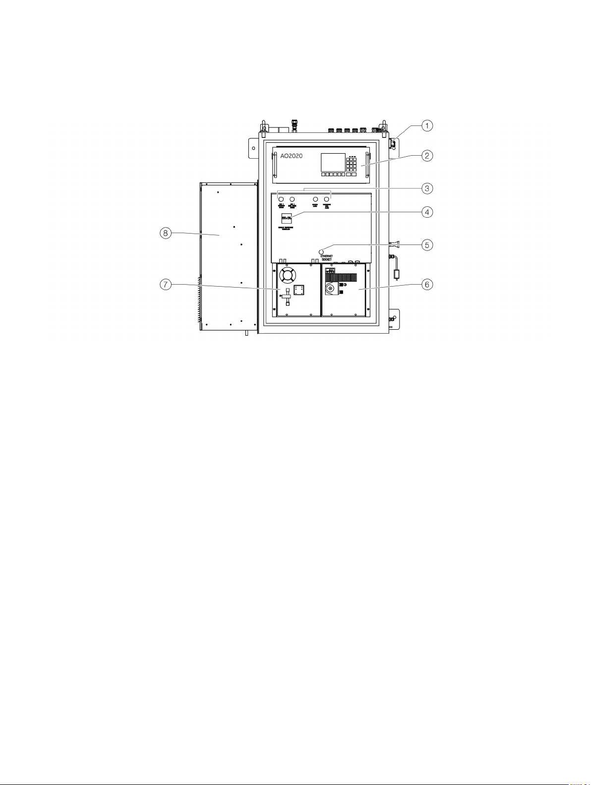
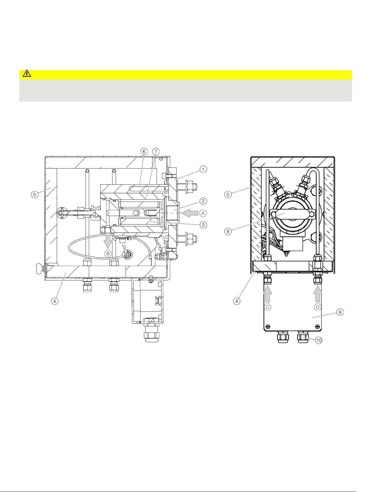
1
2
3
4
5
6
7
8
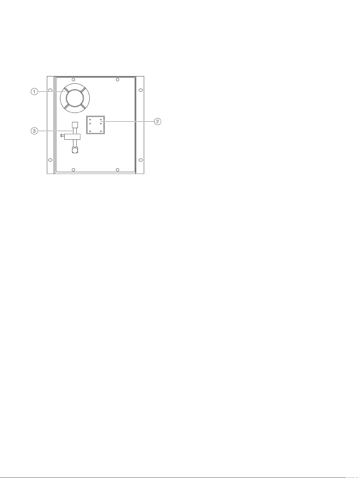
System structure
System cabinet
Main switch
Gas analyzer AO2020
Status indicators for measuring, back purge, general alarm, condensate
level
Heated sample gas line temperature controller
Figure 1: GAA610-M system cabinet
Front Door
The front door can be opened without any risks.
Behind the front door is the front panel, the Sample Gas Feed
Unit SCC-F and the Sample Gas Cooler SCC-C.
Front panel
On top is the NDIR gas analyzer AO2020-Uras26.
Below, on the left side of the status signal board, are signal
lamps as indication of activity of measuring point and backpurging.
Directly below them is the temperature controller for the heated
sample gas line.
In the middle of the status signal board are red LEDs for the
Common Alarm and for the condensate level alarm.
Below the alarm signals is an ethernet socket for maintenance
purpose.
Ethernet port
Sample Gas Cooler SCC-C
Sample Gas Feed Unit SCC-F
Cabinet air conditioner
Cabinet interior
The cabinet contains the sample conditioning components,
pump, valves, filters and gas analyzer.
It also contains the main switch, the power supply and the fuses
for all components, as well as the connection terminals for
analog and digital signals.
Page 12
12 GAA610-M ADVANCED EMISSION GAS MONITORING SYSTEM | OI/GAA610-M-EN REV. B
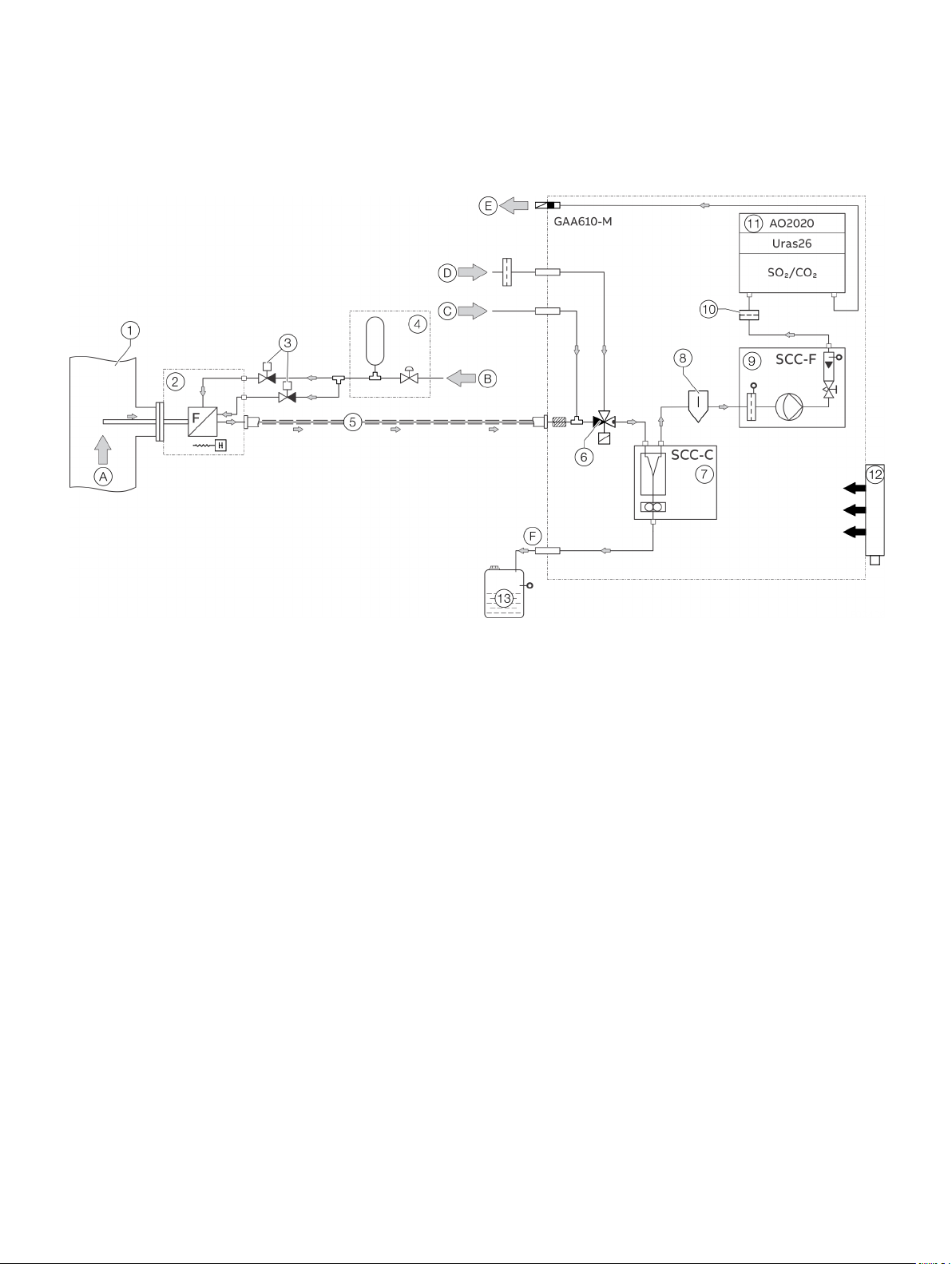
A
B
C
D
E
F
1
2
3
4
5
6
7
8
9
0
k
l
m
… 2 Design and function
… System structure
System schematic
Exhaust gas stream
Compressed instrument air inlet
Calibration gas inlet
Exhaust pipe
Heated sample probe with probe tube and filter unit
Backpurging solenoid valves
Backpurging air panel
Heated sample gas line
Sample gas solenoid valve
Sample gas cooler SCC-C
Figure 2: System schematic
Sample gas flow
The sample gas is extracted from the exhaust duct after the
scrubber by a heated sample probe.
The heated sample gas line is the connection and supplying line
between sample probe and analyzer cabinet. The probe and the
sample gas line are heated to avoid condensation.
To clean the filters in the sample probe a back-purging system
via the filter chamber can be integrated. The filters are cleaned
with pressurized air every 12 hours cyclically or automatically
when the flow is below the minimum value.
At the entrance of the analyzer cabinet there is a 3/2-way
solenoid valve. The gas flow goes to the gas cooler and via filter,
flow meter, pump and aqua stop filter to the gas analyzer.
See also Piping diagram on page 98.
Ambient air / zero gas inlet
Sample gas outlet
Condensate outlet
Oil/Soot removal filter
Sample gas feed unit SCC-F
Aqua stop filter
AO2020 gas analyzer with Uras26
Cooling unit for analyzer cabinet
10 l condensate bottle with condensate alarm switch
Sample probe
The sample probe is connected gas tight to the process with a
flange. The probe tube extracts the gas in the middle of the
exhaust duct.
An external heated filter separates the dust from the sample
gas. The Filter is heated by a self-limiting PTC heater to 180 °C
(356 °F). The filter is equipped with a ceramic filter element.
To clean the filters in the sample probe a back purging system
via the filter can be integrated.
Page 13
GAA610-M ADVANCED EMISSION GAS MONITORING SYSTEM | OI/GAA610-M-EN REV. B 13
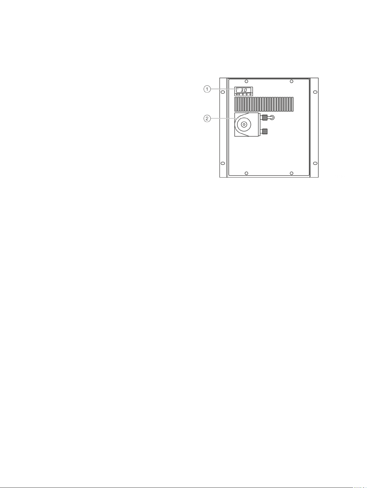
1
2
Heated sample gas line
The heated sample gas line is directly connected to the filter at
the probe. The core is a PTFE hose. The line is heated to 180 °C
(356 °F).
The temperature is controlled with a Pt100 resistance
thermometer and the power/temperature is adjusted with a
temperature controller installed in the cabinet. In case of a
deviation from the set value a message is generated and
displayed on the AO2020-Display.
Temperature controller
A Temperature controller is used to control the temperature of
the heated sample gas line.
An alarm signal is output as soon as the temperature drops
below the minimum temperature limit.
Solenoid valve
A solenoid valve is installed to switch between measuring gas
and ambient air during calibration and standby mode.
Aqua stop filter
The aqua stop filter is the final protection for the analyzer. The
aqua stop filter holds back any humidity.
AO2020-Uras26 gas analyzer
The AO2020-Uras26 gas analyzer is integrated into the analyzer
system for measuring CO
The main components are an infrared source (lamp), a sample
cell, a wavelength filter, and the infrared detector.
The sample gas is pumped into the sample cell, and the gas
concentration is measured electro-optically by its absorption of
a specific wavelength in the infrared wavelength range.
and SO2.
2
Sample Gas Cooler SCC-C
Temperature controller
Figure 3: Sample Gas Cooler SCC -C
The sample gas cooler defines the water content of the sample
at a certain dew point (typically 3 °C). Therefore, the temperature
of the sample falls from approx. 180 °C to the set point of the
sample gas cooler and condensation will occur. The condensate
is removed with a hose pump and collected in a separate bottle.
The sample gas cooler is controlled by the system and the
following signals can be output:
• Condensate level:
The level of the condensate collecting bottle is monitored
and a signal will output (displayed via a red lamp on the
front panel) when maintenance / emptying the bottle is
required.
• Fault cooler:
A status signal "fault cooler" is set if the cooler
temperature is too high. The signal is also provided as
"Failure" status signal.
• Failure alarm:
If a failure of the cooler is detected, the feed pump is
switched off and the system is set to system failure
mode. The system failure mode is displayed on the panel
and provided as a status signal.
Condensate pump
Page 14
14 GAA610-M ADVANCED EMISSION GAS MONITORING SYSTEM | OI/GAA610-M-EN REV. B
1
2
3
… 2 Design and function
… System structure
Sample Gas Feed Unit SCC-F
Condensate monitor
LED display and reset switch for
condensate and flow alarm
Figure 4: Sample Gas Feed Unit SCC-F
Flow monitor with needle valve
The sample gas feed unit sucks the sample from the exhaust gas
and continuously feeds the gas analyzer with the sample gas.
The pump is a diaphragm pump. If the pump fails a flow alarm
occurs.
Flow control
The flow meters monitor the sample gas flow through the
analyzer.
The following parameters are considered:
• Typical flow: 60 l/h
• Minimum flow level: 40 l/h
• Maximum flow level: 80 l/h
• Flow error: 10 l/h
If the flow violates a limit value an alarm is displayed on the front
panel. In addition, the sample probe is automatically
backpurged.
Page 15
GAA610-M ADVANCED EMISSION GAS MONITORING SYSTEM | OI/GAA610-M-EN REV. B 15
Products that are marked with the adjacent symbol
may
(domestic waste).
They should be disposed of through separate
collection of electric and electronic devices.
1
2
3
4
5
6
7
8 Permissible ambient temperature
9
0
k
l
m
Label / Symbol
Quantity
Description
Standard equipment
1
Analyzer cabinet
1
System documentation
Additional items delivered per order
1
Gas sampling probe tube type
1
Filter unit and 2
1
Sample gas line, heated
1
Condensate collection bottle
1
Wear
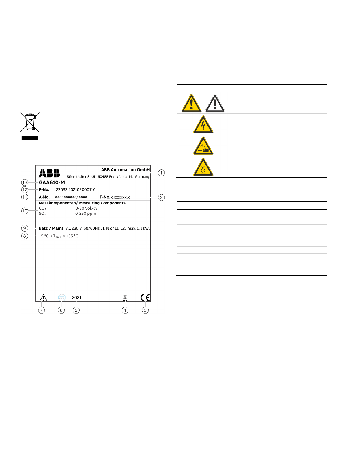
3 Product identification
Name plate
Note
The name plates displayed are examples. The device
identification plates affixed to the device can differ from this
representation.
Note
not be disposed of as unsorted municipal waste
The type plate is located at the top right of the right-hand side
panel of the analyzer cabinet near the cable glands.
Plates and symbols
The following labels and symbols are attached to the analyzer
system or to the individual components.
Meaning
Consult documentation, i.e. consult this
operating instruction.
Risk of electric shock!
Corrosive material!
Hot surface!
(Temperature > 60 °C)
Scope of delivery
Manufacturer, address
Serial number
CE marking
Disposal marking
Manufacture date
Type approval marking
‘Observe operating instruction’
symbol
Figure 5: Name plate (example)
range
Power supply
Measuring Components
Order number
Product configuration number
Model name
×
× set
×
×
×
×
×
40 (unheated)
-stage back-purging unit
parts set (optional)
Page 16
16 GAA610-M ADVANCED EMISSION GAS MONITORING SYSTEM | OI/GAA610-M-EN REV. B
CAUTION
cables to the analyzer cabinet.
NOTICE
the analyzer cabinet can be warped.
4 Transport and storage
Safety instructions
Injury hazard due to heavy weight
Depending on the version, the gas analyzer cabinet weighs
approx. 240 kg (529 lb)!
• A suitable lifting device (crane, block and tackle, lifting
truck, etc.) is required for transport, setting upright and
installation!
• Only use the handling lugs provided to connect any lift
Inspection
Check the devices immediately after unpacking for possible
damage that may have occurred from improper transport.
Details of any damage that has occurred in transit must be
recorded on the transport documents.
All claims for damages must be submitted to the shipper
without delay and before installation.
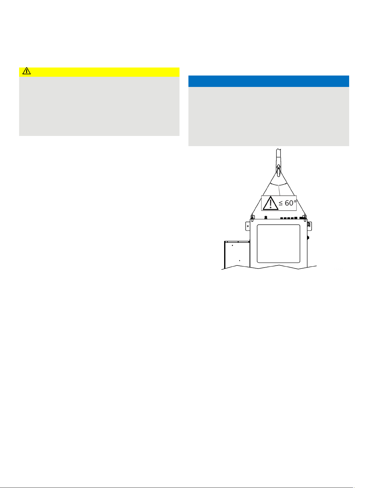
Transporting the device
Transporting the analyzer cabinet
Potential damage to the device!
Damage to the device due to improper transport.
• Use the handling lugs provided to connect any lift cables
to the analyzer cabinet.
• The lift cable must be long enough to have an angle of at
least 60° relative to the top of the cabinet when under
tension. If this is not done the handling lugs can be bent or
Figure 6: Lift-Up the analyzer cabinet
Note
It is strongly recommended that the analyzer cabinet is
transported by a specialist firm, transported in a horizontal
position!
Unpacking the analyzer cabinet
1. Lift out the analyzer cabinet from the shipping box.
2. Do not remove the plastic sheet in which the analyzer cabinet
is wrapped. Unpacking a cold analyzer cabinet can lead to
condensation.
3. Remove the plastic sheet only once the analyzer cabinet is at
room temperature. This takes at least 24 hours.
Page 17

GAA610-M ADVANCED EMISSION GAS MONITORING SYSTEM | OI/GAA610-M-EN REV. B 17
Storing the device
Bear the following points in mind when storing devices:
• Store the device in its original packaging in a dry and
dust-free location.
• Observe the permitted ambient conditions for transport
and storage.
• Avoid storing the device in direct sunlight.
• In principle, the devices may be stored for an unlimited
period. However, the warranty conditions stipulated in
the order confirmation of the supplier apply.
Ambient conditions
Ambient temperature during transport / storage
• 2 to 60 °C (35.6 to 140 °F);
• −20 to 70 °C (−4 to 158 °F) after draining and drying parts
in contact with condensate.
Max. permissible humidity
Year-round average max. 75%, short-term max. 95%,
occasional slight condensation is permitted.
Packaging
1. If the original packing material is no longer available, wrap
the device in bubble foil or corrugated cardboard.
When shipping overseas, also heat-seal the device air-tight in
0.2 mm thick polyethylene, including a desiccant (e.g. silica
gel). The amount of desiccant used should be adequate for
the package volume and the probable shipping time (at least
3 months).
2. Pack the device in an adequately large box lined with shock
absorbent material (e.g. foam material). The thickness of the
cushioning material should be adequate for the weight of the
device and the mode of shipping. The box should also be
lined with a double layer of bitumen paper for overseas
shipping.
3. Mark the box ‘Fragile! Handle with care!’.
Returning devices
Use the original packaging or a secure transport container of an
appropriate type if you need to return the device for repair or
recalibration purposes.
Fill out the return form (see Return form on page 99) and include
this with the device.
In accordance with the EU Directive governing hazardous
materials, the owner of hazardous waste is responsible for its
disposal or must observe the following regulations for shipping
purposes:
All devices delivered to ABB must be free from any hazardous
materials (acids, alkalis, solvents, etc.).
Address for the return:
Contact Center
www.abb.com/contacts
Page 18
18 GAA610-M ADVANCED EMISSION GAS MONITORING SYSTEM | OI/GAA610-M-EN REV. B
CAUTION
cables to the analyzer cabinet.
DANGER
locations.
1
2
3
4
5
5 Preparation for Installation
Safety instructions
Injury hazard due to heavy weight
Depending on the version, the gas analyzer cabinet weighs
approx. 240 kg (529 lb)!
• A suitable lifting device (crane, block and tackle, lifting
truck, etc.) is required for transport, setting upright and
installation!
• Only use the handling lugs provided to connect any lift
Note
• The system must be installed by ABB or by personnel trained
by ABB.
• When installing the analyzer system, in addition to this
operating instruction, comply with the information
contained in the drawings set.
• If there is shipping damage which points to improper
handling file a damage claim with the shipper (railway, mail
or freight carrier) within seven days.
• Make sure the enclosed accessories are not lost.
• Keep the packaging material for future shipping needs.
Requirements for the installation site
Risk of explosion
The analyzer system must not be installed in hazardous
Choosing the extraction point
The extraction point must be suitable for extracting a
representative specimen flow.
In case of emission monitoring of exhaust gases, the extraction
point is specified in accordance with responsible technical
inspection authority, e.g. classification society.
Wall tube installation
Installation – Overview
1. Prepare the gas sampling probe installation site, see
Choosing the extraction point on page 18.
2. Prepare the analyzer cabinet installation site, see
Requirements for the installation site on page 18.
3. Install the gas sampling probe and filter unit, see Probe tube
and filter unit installation on page 25.
4. Install the sample gas line, see Sample gas line installation
on page 27.
5. Install the back-purging unit (if applicable), see Back-purging
unit installation on page 29.
6. Install the analyzer cabinet, see Analyzer cabinet installation
on page 30.
7. Install the instrument air and test gas supply
(if applicable), see Gas connections on page 31.
8. Connect the gas lines to the analyzer cabinet, see
Connecting the gas lines on page 32.
9. Connect the electrical leads to the analyzer cabinet, see
Electrical connections on page 33.
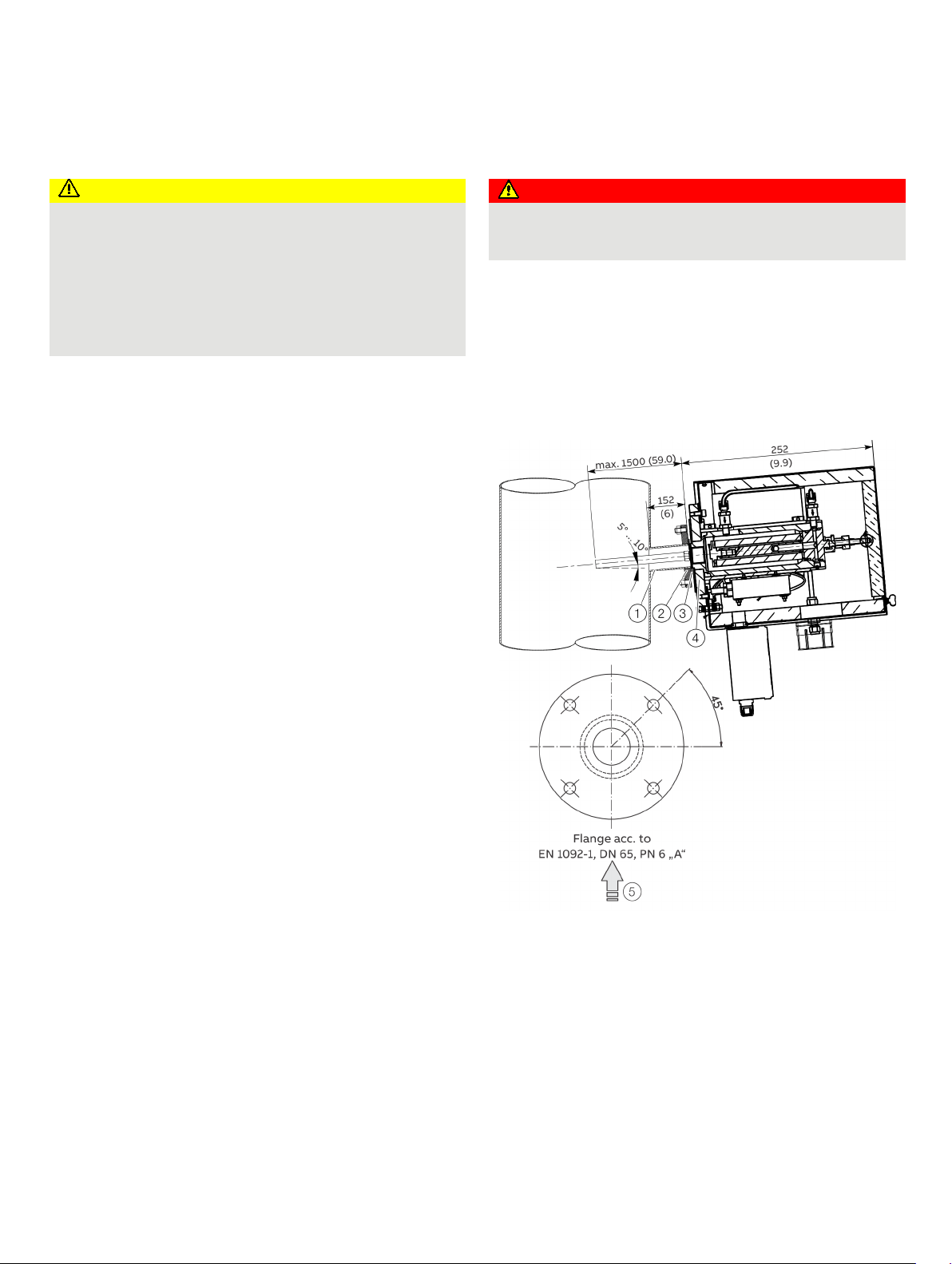
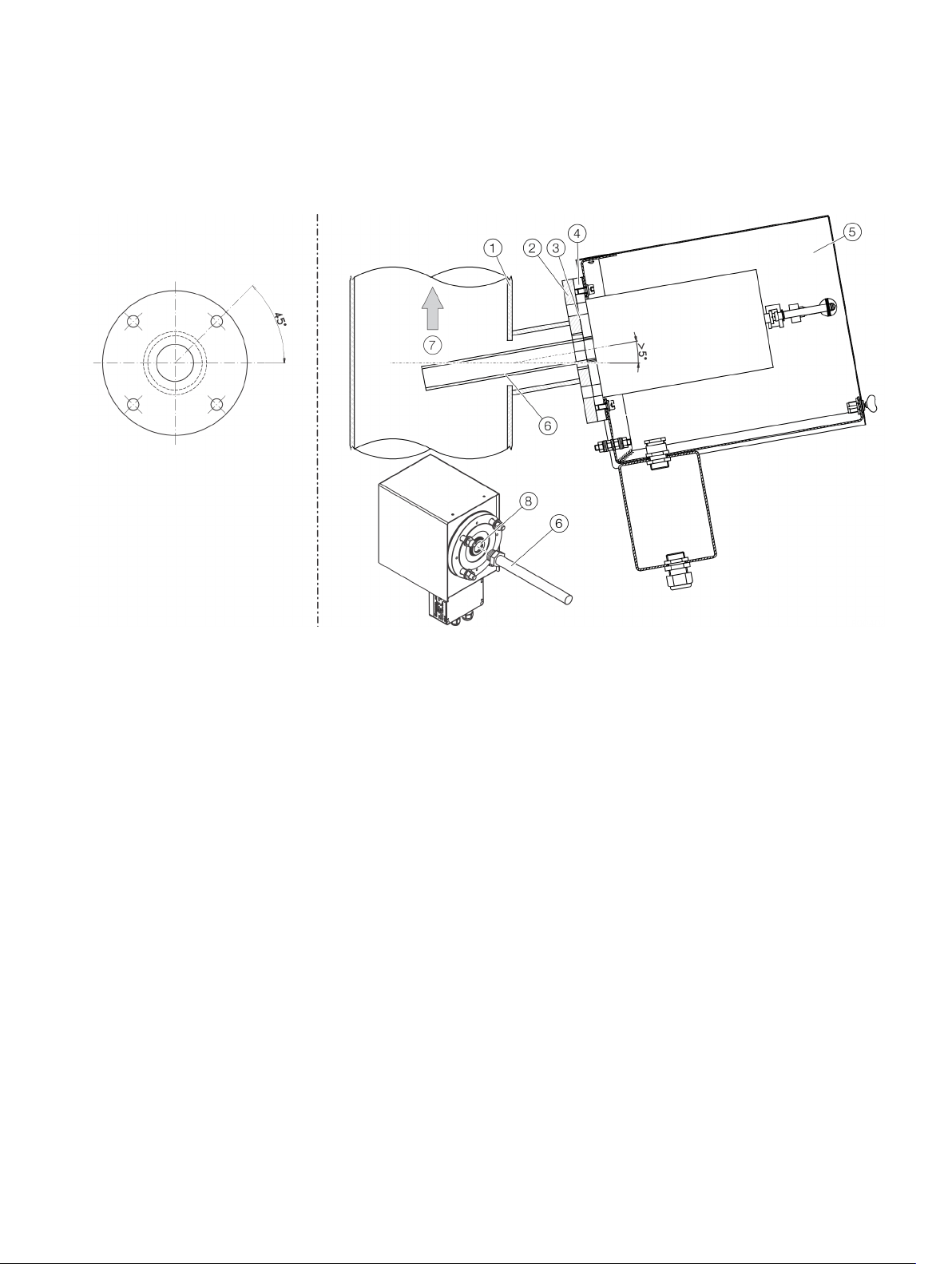
Wall tube
Wall tube mounting flange
Gasket
Figure 7: Wall tube installation, Dimensions in mm (inch)
Sample probe tube flange
Flow direction
Install the wall tube with mounting flange (DN 65, PN 6, facing
type A to EN 1092-1; not supplied) at the extraction point in such
a way that the sampling probe tube can be easily installed and
removed.
The sampling probe tube must be easily accessible to allow
maintenance work to be performed. Align the boreholes of the
mounting flange in relation to the flow direction
5 of the
process gas.
Page 19

GAA610-M ADVANCED EMISSION GAS MONITORING SYSTEM | OI/GAA610-M-EN REV. B 19
Short gas paths
The analyzer cabinet should be installed as close as possible to
the sampling site. A short sample gas line results in short T
times.
The sample gas line length is limited to 30 meters with 230 VAC
power on account of pressure drop build-up in the line and the
required electrical fusing.
The test gas cylinders should be installed as close as possible to
the analyzer system. Test gas cylinders are only required for
regular adjustment during operation if CEMS is not equipped
with internal gas filled cells.
Protection from adverse ambient conditions
Protect the gas analyzer cabinet from the following influences:
• Water spray
• Contact with chemicals
• Strong sunlight and heat radiation
• Strong air currents
• Heavy dust load
• Corrosive atmospheres
Installation indoors
The analyzer system is intended for installation aboard a ship.
Thereby, the installation location height is naturally limited to
sea level.
The analyzer cabinet is only suitable for installation indoors. An
air-conditioned room is recommended.
Dimensions and space requirement
Refer to Dimensions on page 21 in the drawings set.
Installation site stability
The installation site floor must be plane and the wall capable of
supporting the cabinets weight.
90
Climatic Conditions
Ambient temperature
In operation: 5 to 55 °C* (41 to 131 °F)*
* Higher ambient temperature during operation on request.
Ambient temperature during transport / storage
• 2 to 60 °C (35.6 to 140 °F);
• −20 to 70 °C (−4 to 158 °F) after draining and drying parts
in contact with condensate.
Max. permissible humidity
Year-round average max. 75%, short-term max. 95%,
occasional slight condensation is permitted.
IP rating
IP 54
Vibration resistance in accordance with IEC 60068-2-6
Vibrations according the below tested conditions showed
negligible influence on measurement value.
Test Fc:
±1.0 mm, 2
0.7 g at 13.2 Hz up to 100 Hz
Overvoltage category
II
Pollution degree
2
+3
Hz up to 13.2 Hz;
−0
Page 20
20 GAA610-M ADVANCED EMISSION GAS MONITORING SYSTEM | OI/GAA610-M-EN REV. B
GAA610-M – Instrument air inlet conditions
Quality
Oil free, dry with dew point < −20 °C (−4 °F)
Pressure
Min. 400 kPa (60 psig)
Max. 600 kPa (90 psig)
Air consumption
< 0.2 Nm3/day
NOTICE
• Only use dry and clean compressed air.
Power supply
Terminals
: L, N, PE or L1, L2, PE
Operating voltage
%
Frequency
50 / 60 Hz, ±3 Hz
External fuse
A
Power consumption
System cabinet
w
Air conditioner
W
Sampling probe
300 W
Heated sample gas line
W/m
DANGER
ignitable gas / air or gas / oxygen mixtures
GAA610-M – Sample gas inlet conditions
Temperature
Max. 500 °C (932 °F)
Pressure
850
… 5 Preparation for Installation
Backpurging Unit
Design of the back-purging unit
The back-purging unit consists of a protective cabinet with shutoff valve, 6 bar pressure reduction valve, solenoid valves for
back-purging, pressure regulator and 2 l compressed air receiver
(pressure buffer tank) for effective pressure pulses also with
lower airflow rate.
Distance to sampling probe
The distance between the back-purging unit and the sampling
probe should be as short as possible and must not exceed 2 m
(6.6 ft).
Protection from adverse ambient conditions
Protect the back-purging unit against:
• Water spray
• Contact with chemicals
• Strong sunlight and heat radiation
• Strong air currents
• Heavy dust load
• Corrosive atmospheres
• Vibration
Instrument air supply
Compressed air for back-purging
Power supply
-X60
230 V AC, ±10
25
500
1600
Approx. 90
Sample gas inlet conditions
Explosion hazard
Explosion hazard when measuring ignitable gas / air or
gas / oxygen mixtures
• The gas analyzer may not be used for the measurement of
to 1100 hPa (0.85 to 1.1 bar), (12.3 to 16 psi)
Damage to the sample conditioning components
If the compressed air is not dry and clean, this will result in
damage to the sample conditioning components (valves,
filters, sample gas cooler, sample gas feed unit) as well as to
the gas analyzer.
Page 21
GAA610-M ADVANCED EMISSION GAS MONITORING SYSTEM | OI/GAA610-M-EN REV. B 21
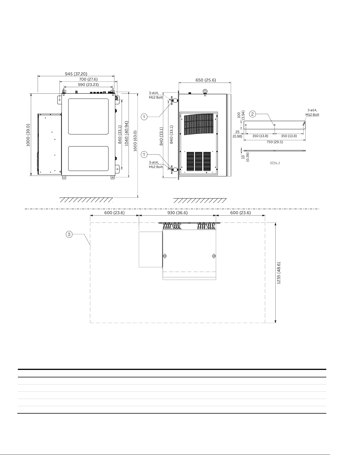
1
2
3
Component
Weight
Analyzer cabinet
240 kg (441 lb), depending on configuration
Probe tube type 40
Filter unit, heated, with protective case
20 kg (44 lb)
Back Purging Unit
Heated sample gas line type TBL01-S
1 kg/m (2.2 lb/m)
Dimensions
Analyzer cabinet
Vibration damper
Mounting plate for vibration dampers
Figure 8: Dimensions an alyzer cabinet, mm (in)
Weight of the individual system components
8 kg (18 lb)
Approx. 5 kg (11 lb)
Maintenance area
Page 22
22 GAA610-M ADVANCED EMISSION GAS MONITORING SYSTEM | OI/GAA610-M-EN REV. B
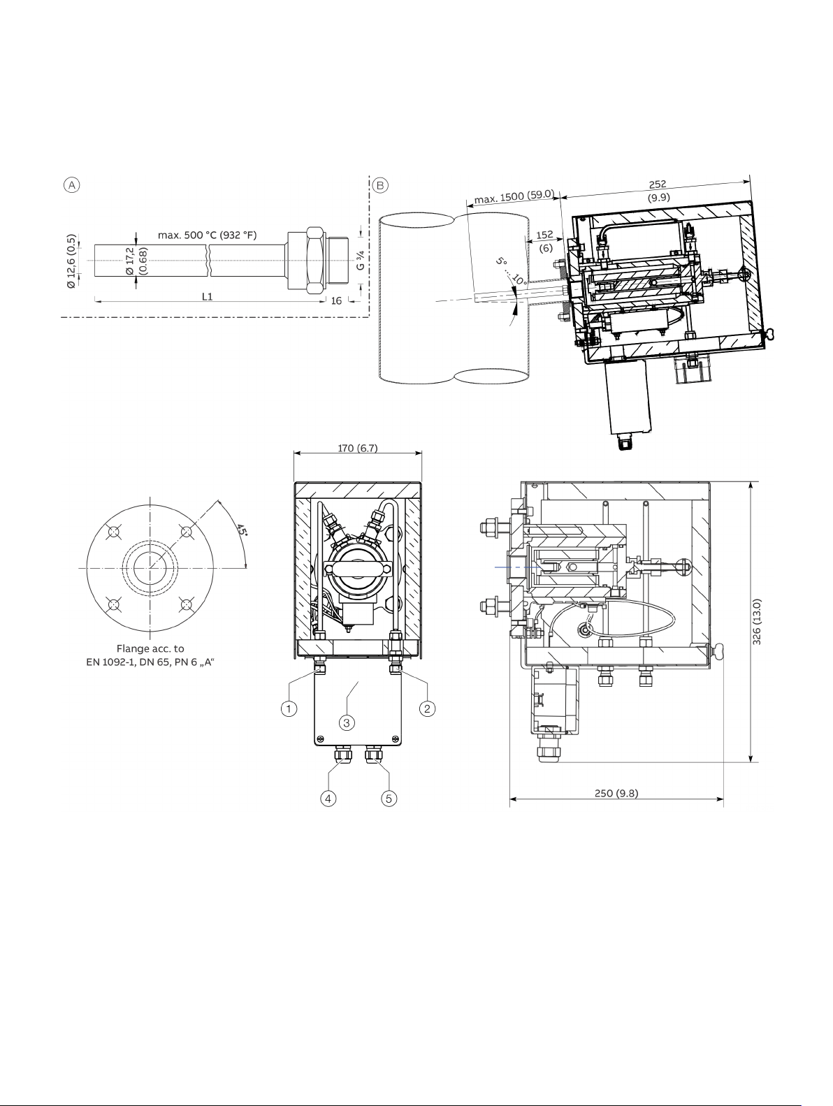
A
B
1
2
3
4
5
L1
… 5 Preparation for Installation
… Dimensions
Type 40 probe tube and filter unit
Type 40 probe tube
Backpurging air inlet from solenoid valve S0V2
Backpurging air inlet from solenoid valve S0V1
Sample gas outlet (heated sample gas line)
Figure 9: Type 40 probe tube and filter unit
Heated filter unit
Cable gland for heated filter unit power supply
Cable gland for heated filter unit alarm signal
500 mm (19.7 in) / 1000 mm (39.4 in)
Page 23
GAA610-M ADVANCED EMISSION GAS MONITORING SYSTEM | OI/GAA610-M-EN REV. B 23
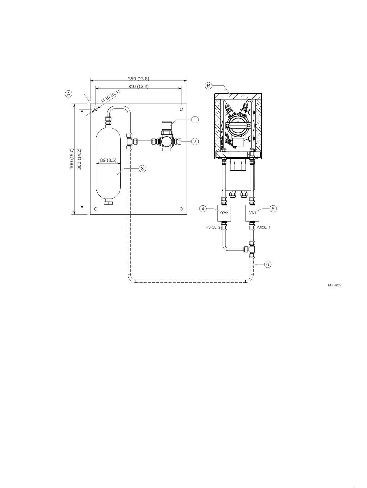
A
B
1
2
3
4
5
6
Backpurging Unit
Backpurging panel
Pressure regulator
Instrument air inlet, 10 mm O.D. Tube fitting for stainless steel pipe
Pressure buffer tank
Figure 10: Backpurging panel
Filter unit
Backpurging solenoid valve SOV2
Backpurging solenoid valve SOV1
Stainless steel pipe 10 mm O.D., to be intalled by customer
Page 24

24 GAA610-M ADVANCED EMISSION GAS MONITORING SYSTEM | OI/GAA610-M-EN REV. B
Gas line
Material
Sample gas
PTFE pipe 4/6×1 mm
Sample gas outlet
PTFE pipe 4/6×1 mm
Ambient air / Zero (N
2
PTFE pipe 4/6×1 mm
Calibration gases 1, 2, 3
PTFE pipe 4/6×1 mm
Instrument air
,
via tube fitting
Condensate collecting bottle
PVC tube 4/6×1 mm
Power supply lines
Analyzer cabinet supply
Connecting cables between analyzer cabinet and sample handling
components
Sample probe power supply
Probe Heater Alarm Signal
• Cable Type: 2×0.75 mm2
Back
Valves (SOV1/SOV2)
Signal lines (Connection between CEMS cabinet and scrubber system)
Analogue Signals to DCS
(only, if hardwired
connection is required)
• Cable Type: 6×1 mm2
Digital Signals to DCS
(only, if hardwired
connection is required)
(Measuring Range Feedback SO2)
Modbus Signal to DCS
Cable Entry: M20 Cable gland for customer supply
cable
Ethernet to DCS
supply
… 5 Preparation for Installation
Material required for installation
Note
The materials listed below are not included in the scope of
delivery of the device, and must be provided by the customer.
Gas sampling
Wall tube with mounting flange
DN 65, PN 6, facing type A to EN 1092-1.
Gas lines
(unheated line)
)
Stainless steel pipe, 10 mm
Mounting material
Screws and nuts to mount the analyzer cabinet on the wall.
A suitable lifting device (crane, block and tackle, lifting truck,
etc.) and lifting gear are required for transport and installation
of the analyzer cabinet.
For details regarding the size of the screws and nuts see the
‘Layout Plan’ in the drawings set.
Cable specification
Note
All cables entering the system must comply with the
flammability class VW1, FT1 or EN60332-1-2/-2-2.
• 230 V AC, 50 / 60 Hz, Single Phase NON-UPS
power supply; fuse (external) 25A
• Cable Entry: M25 Cable gland for customer
supply cable;
• Cable Type: 3×10 mm2
• Grounding cabl e: > 6 mm2
• 230 V AC 50/60 Hz;
• Cable Entry: M20 Cable gland for customer
supply cable;
• Cable Type: 3×2.5 mm2
• Cable Entry: M20 Cable gland for customer
supply cable
-purge Unit Solenoid
• Cable Entry: M20 Cable gland for customer
supply cable
• Cable Type: 2×1.5 mm2
• Shielded cables for the analog outputs
(current outputs)
• Cable Entry: M25 Cable gland for customer
supply cable
• Cable Entry: M20 Cable gland for customer
supply cable
• Cable Type: 2×1 mm2 (System failure)
• Cable Type: 2×1 mm2 (Maintenance)
• Cable Type: 2×1 mm
(Maintenance Request)
• Cable Type: 2×1 mm
Cable Entry: M20 Cable gland for customer
cable
2
2
Note
Further signal lines might be needed, please check your specific
wiring diagram.
Page 25
GAA610-M ADVANCED EMISSION GAS MONITORING SYSTEM | OI/GAA610-M-EN REV. B 25
CAUTION
• Two persons are required for transportation and mounting!
A
B
C
D
1
2
3
4
5
6
7
8
9
0
6 Installation
Probe tube and filter unit installation
Injury hazard due to heavy weight
The weight of the probe tube with filter unit amounts to approx. 18 to 20 kg!
Before the installation
• Observe the ‘Piping plan’ in the drawings set.
• Make sure that the wall tube is installed at the extraction point, see .
Filter unit overview
Sample gas inlet
Sample gas outlet
Backpurging air inlet from solenoid valve S0V2
Backpurging air inlet from solenoid valve S0V1
Flange
Internal thread connection for probe tube
Filter element
Figure 11: Filter unit
Housing with thermal Insulation
Cover with thermal insulation
Heater element
Filter housing
T-handle
Terminal box for heater power supply and status contact
Cable glands
Page 26
26 GAA610-M ADVANCED EMISSION GAS MONITORING SYSTEM | OI/GAA610-M-EN REV. B
Flange orientation
Filter unit
1
2
3
4
5
6
7
8
… 6 Installation
… Probe tube and filter unit installation
Installation
Duct wall
Flange
Flange gasket
Probe flange
Figure 12: Filter unit installation
Filter Unit
Probe tube
Flow direction
Sample gas inlet
1. Screw the probe tube 6 into the sample gas inlet 8 of the filter unit.
2. Insert the pre-assembled probe tube with filter unit in the wall tube and screw the flange of the filter unit to the flange of the wall
tube. Use the green seal from the accessories pack to seal the space between the flanges of wall tube and filter unit.
3. Mount the heating sleeve on the filter unit.
4. If applicable, install the compressed-air hoses between the filter unit and the back-purging unit.
Page 27
GAA610-M ADVANCED EMISSION GAS MONITORING SYSTEM | OI/GAA610-M-EN REV. B 27
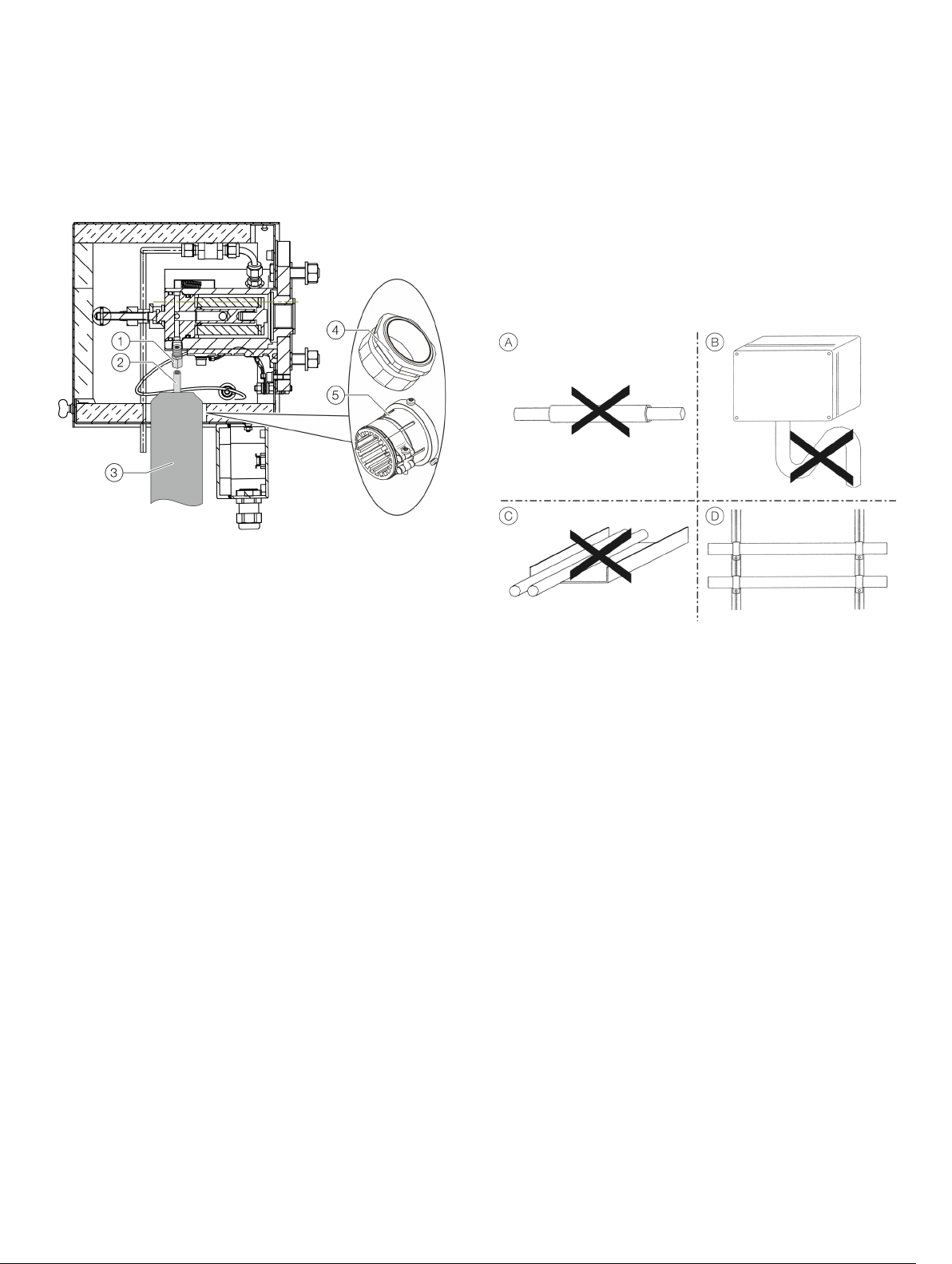
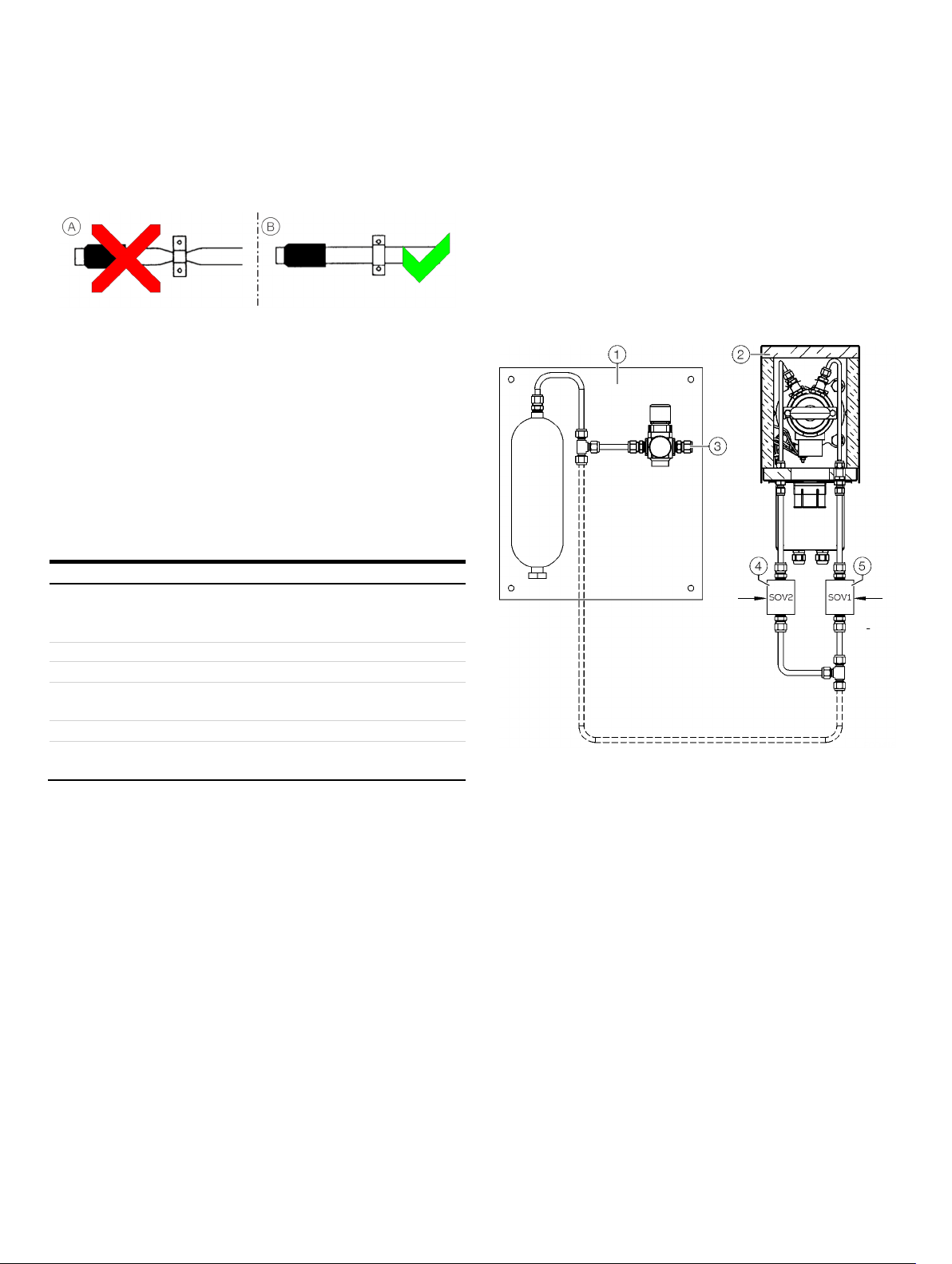
Connection of the heated sample gas line
Figure 13: Connection of the heated sample gas line
Note
The heated sample line must be strain relieved and must not be
hung on the fitting.
1. Mount ⅛“ NPT fitting
unit.
2. Attach heated sample line
moveable PG 42 cable conduit
3. Connect the line
1 at the sample gas outlet of the filter
3 on probe enclosure with
4 or mounting clamp 5.
2 with the fitting 1 gas-tight.
Sample gas line installation
Installing the sample gas line
• Observe the "Piping plan" in the drawings set.
• Connect the sample gas line to the filter unit/gas sampling
probe.
• Route the sample gas line through the opening provided in
the top of the cabinet.
Fundamentals for laying the sample gas line
Figure 14: Laying the sample gas line
A Do not lay the heated sample gas line in a thermowell.
B When laying the sample gas line, avoid the formation of
water locks, particularly at the sampling points.
C Do not lay the heated sample gas line in a cable tray together
with other electrical or pneumatic lines, especially not in an
enclosed cable tray.
D When laying the heated sample gas lines on exposed C-
profiles with BBS cable clips: Do not overtighten the cable
clips, in order to prevent damage to the sample gas line
through crushing.
Page 28
28 GAA610-M ADVANCED EMISSION GAS MONITORING SYSTEM | OI/GAA610-M-EN REV. B
Incorrect
Correct
Incorrect
Correct
Incorrect
Correct
Incorrect
Correct
Incorrect
Correct
… 6 Installation
… Sample gas line installation
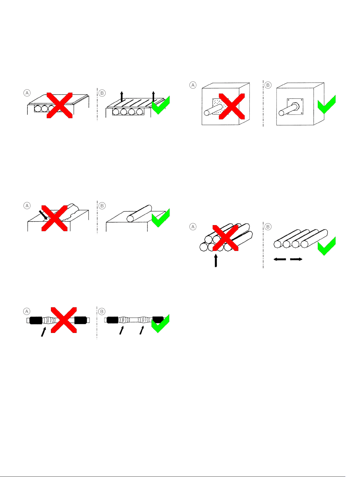
Procedures for laying the sample gas line
Wall break-through
Laying in ducts or shafts
Figure 15: Laying in ducts or shafts
A Do not lay the heated sample gas lines directly side-by-side
in an enclosed duct or shaft. This results in heat
accumulation.
B Ensure that the hoses do not touch. Maintain a distance of
25 mm. Provide adequate ventilation. Heat can be conducted
away as a result.
Soiling the heated sample gas line
Figure 18: Wall break-through
A Do not lay the heated sample gas line in a wall break-through
which is subsequently sealed with a sealing compound under
any circumstances. The sample gas line will be destroyed by
overheating in this case!
B When laying the heated sample gas line through a wall break-
through, use bulkhead plates with conduit thread cable
glands, in order to provide adequate cooling of the sample
gas line.
Laying several heated sample gas lines
Figure 16: Soiling
A Prevent powdery substances, adhesives or other thermally
insulating materials from soiling the heated sample gas line.
Otherwise, over\-heating will occur at these points.
B If soiling occurs, clean the materials and remedy the cause.
Heat can be conducted away again as a result.
Wrapping the heated sample gas line
Figure 17: Wrapping
A Avoid heat accumulation through wrapping the heated
sample gas line with other materials, otherwise the sample
gas line will overheat at these points. Do not cover the area
near the temperature sensor, otherwise the rest of the
sample gas line will cool down.
B Do not wrap the sample gas line. Ensure that the area near
the temperature sensor is exposed.
This results in error-free temperature measurement.
Figure 19: Bundling several gas lines
A Avoid bundling or laying several heated sample gas lines, so
that they touch each other. This results in overheating at the
contact points.
B Lay several heated sample gas lines separately with a
distance of at least 2.5 cm and provide adequate ventilation.
Heat can be conducted away as a result.
Page 29
GAA610-M ADVANCED EMISSION GAS MONITORING SYSTEM | OI/GAA610-M-EN REV. B 29
Incorrect
Correct
Characteristic
Permissible value
Type
W/m if other is used
Maximum line length
Minimum bending radius
300 mm
Maximum clip distance
Lowest laying temperature
−10 °C
Temperature of the
sheathing
1
2
3
4
5
Mounting brackets
Back-purging unit installation
Before the installation
Observe the ‘Piping plan’ in the drawings set.
Installation site
The distance between the back-purging unit and the sampling
probe should be as short as possible and must not exceed 2 m
(6.6 ft).
Figure 20: Mounting brackets
A Do not squeeze the heat insulation in mounting brackets
Connecting the compressed-air tubes
tightly together, so that the outer braiding is pressed on to
the heat conductor. If you disregard this, damage to the
protective braiding and the heated sample gas line may
occur.
B Tighten the BBS cable clips sufficiently but not excessively, in
order to prevent damage to the protective braiding and the
heated sample gas line.
Permissible values for laying the sample gas line
Heated, Type TBL01-S, regulated heating, 180 °C,
heating power 90 W/m (TBL01-S); approx. 100
230 V AC: max. 30 m
1.2 m with horizontal laying
3.5 m with vertical laying
max. 60 °C
Back-purging panel
Filter unit
Instrument air inlet
Figure 21: Connecting the back purging unit
Solenoid valve SOV2
Solenoid valve SOV2
1. Mount the solenoid valves on the filter unit as illustrated.
2. Connect the compressed-air pipes for purge air and control
air to the respective ports at the filter unit.
3. Connect the electrical cables of the solenoid valves to the
corresponding terminal strip in the analyzer cabinet. For
details see the wiring diagram or Terminal assignment –
Analyzer cabinet on page 35.
Page 30
30 GAA610-M ADVANCED EMISSION GAS MONITORING SYSTEM | OI/GAA610-M-EN REV. B
CAUTION
cables to the analyzer cabinet.
NOTICE
the analyzer cabinet can be warped.
NOTICE
following points:
… 6 Installation
Analyzer cabinet installation
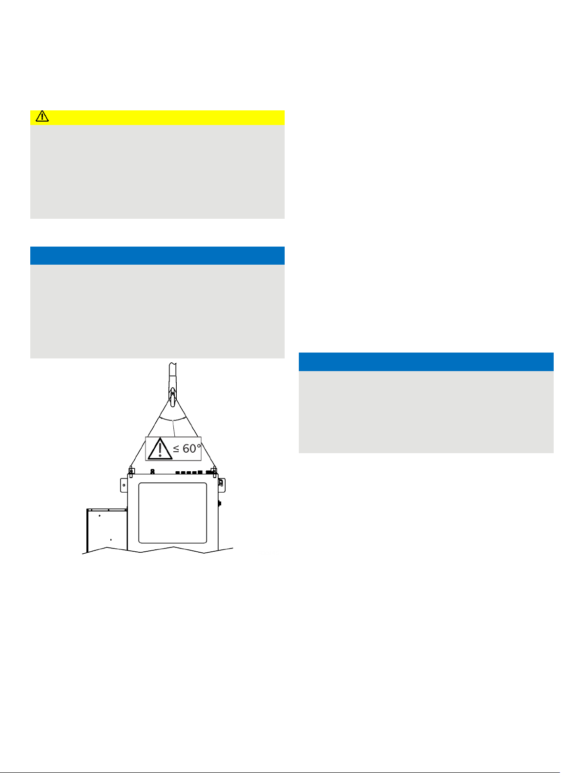
Injury hazard due to heavy weight
Depending on the version, the gas analyzer cabinet weighs
approx. 240 kg (529 lb)!
• A suitable lifting device (crane, block and tackle, lifting
truck, etc.) is required for transport, setting upright and
installation!
• Only use the handling lugs provided to connect any lift
Transporting the analyzer cabinet
Potential damage to the device!
Damage to the device due to improper transport.
• Use the handling lugs provided to connect any lift cables
to the analyzer cabinet.
• The lift cable must be long enough to have an angle of at
least 60° relative to the top of the cabinet when under
tension. If this is not done the handling lugs can be bent or
Mounting the analyzer cabinet
• Observe the installation site requirements.
• The loading capacity of the wall must be high enough to bear
the weight of the analyzer cabinet.
• Follow the ‘Layout plan’ in the drawings set.
• The vibration dampers are ready pre-installed. For easy
installation, the upper and lower vibration dampers are each
connected to a mounting plate. See also Dimensions on
page 21.
1. Mount the cabinet with the vibration dampers on the wall
and fix it to the screw holes provided on the mounting plate
using M12 Bolts.
2. Tighten all screws of the analyzer cabinet.
3. Ground the analyzer cabinet by means of the grounding bolt
(grounding cable ≥ 6 mm
Connecting the condensate water drain of the cabinet air conditioner
2
/≥ AWG 10).
Figure 22: Lift-Up the analyzer cabinet
Note
It is strongly recommended that the analyzer cabinet is
transported by a specialist firm, transported in a horizontal
position!
Unpacking the analyzer cabinet
1. Lift out the analyzer cabinet from the shipping box.
2. Do not remove the plastic sheet in which the analyzer cabinet
is wrapped. Unpacking a cold analyzer cabinet can lead to
condensation.
3. Remove the plastic sheet only once the analyzer cabinet is at
room temperature. This takes at least 24 hours.
Damage to the cabinet air conditioner
Damage to the cabinet air conditioner due to incorrect
connection of the condensate drain and overflow of the
condensate pan.
• When connecting the condensate water drain port (TP10)
of the analyzer cabinet air conditioner, observe the
• When routing the drain tube, caution should be taken to keep
it from kinking or being elevated above the exit point of the
air conditioner.
• The drain tube must be on a continuous downward slope. A
slight elevation of the tube could result in secondary trap.
Page 31

GAA610-M ADVANCED EMISSION GAS MONITORING SYSTEM | OI/GAA610-M-EN REV. B 31
Pos. Connection
Design
TSG2 Sample gas
T
TP7
Calibration gas inlet
—
Tube fitting for PTFE pipe 4/6 × 1 mm
TP8 Sample gas outlet / Analyzer cabinet
ATM vent
Tube fitting for
TP9
Condensate water drain port
—
Tube fitting DN 6 / 4 mm, PVDF
TP10 Condensate water drain port
10
— Instrument air inlet
10
or
compressed
(plus pressure gauge and shut-off valve)
7 Gas connections
Position and design of the gas connections
Figure 23: Gas connections GAA610-M
Additional Information
inlet For heated sample gas line TBL01 with outer diameter of
From air condition
Located at the backpurging panel, see Backpurging Unit
48 mm
Vent out room safety area
on page 23
ube fitting 4/6 × 1 mm
PTFE pipe 10/12 × 1 mm
mm tube
mm O.D. Tube fitting for stainless steel pipe
-air hose
Page 32

32 GAA610-M ADVANCED EMISSION GAS MONITORING SYSTEM | OI/GAA610-M-EN REV. B
… 7 Gas connections
Connecting the gas lines
Connecting the heated sample gas line
Connect the heated sample gas line as shown in system
schematic Figure 2 on page 12:
1. Lead the heated sample gas line through the TSG2 inlet
into the analyzer cabinet.
2. Mount the heated sample gas line in the holding clamp.
3. Connect the PTFE hose of the heated sample gas line to
the sample gas valve.
4. Insulate the PTFE hose of the heated sample gas line to
the sample gas valve with the insulation supplied.
5. Insulate the PTFE hose from the sample gas valve to the
SCC-C with the insulation supplied.
Calibration gas
Connect the gas lines according to the piping plan.
Connecting the condensate bottle
The Condensate bottle is connected to the sample gas cooler
and must be emptied when alarm of level switch is displayed.
Connecting the sample gas outlet
Observe the following points when connecting the exhaust air
pipe:
• The measured stack gas must be returned to the process
or discharged in a suitable exhaust duct.
• Use PTFE or stainless steel as the material for the exhaust
air line.
• Install the exhaust air line at a gradient, leading away
from the gas analyzer.
• At a maximum of 30 cm after the exhaust air outlet, the
exhaust air pipe must have an inside diameter of
≥ 10 mm!
If the exhaust air pipe is very long, its inside diameter
must be much larger than 10 mm, otherwise you might
have problems with pressure control in the gas analyzer.
• Do not install any throttle sections or shut-off valves in
the exhaust air line!
Note
Dispose of corrosive, toxic or combustion exhaust gases
according to the regulations!
Page 33

GAA610-M ADVANCED EMISSION GAS MONITORING SYSTEM | OI/GAA610-M-EN REV. B 33
WARNING
electrical connection.
Power supply lines
Analyzer cabinet supply
Connecting cables between analyzer cabinet and sample handling
components
Sample probe power supply
Probe Heater Alarm Signal
• Cable Type: 2×0.75 mm2
Back
Valves (SOV1/SOV2)
Signal lines (Connection between CEMS cabinet and scrubber system)
Analogue Signals to DCS
(only, if hardwired
connection is required)
• Cable Type: 6×1 mm2
Digital Signals to DCS
(only, if hardwired
connection is required)
Modbus Signal to DCS
Cable Entry: M20 Cable gland for customer supply
cable
Ethernet to DCS
customer supply
8 Electrical connections
Safety instructions
Risk of injury due to live parts.
Improper work on the electrical connections can result in
electric shock.
• Connect the device only with the power supply switched
off.
• Observe the applicable standards and regulations for the
The electrical connection may only be established by authorized
specialist personnel and in accordance with the connection
diagrams.
The electrical connection information in this manual must be
observed; otherwise, the IP rating may be adversely affected.
Ground the measurement system according to requirements.
Protective lead connection
The protective lead (ground) should be attached to the
protective lead connector before any other connection is made.
Risks of a disconnected protective lead
The device can be hazardous if the protective lead is interrupted
inside or outside the device or if the protective lead is
disconnected.
Notes
• Lay the signal lines separate from the power supply lines.
Carefully plan the combination of signal lines in cables.
• The analyzer system must be hardwired!
• When installing the electrical connections, comply with the
information contained in the drawings set. The connection
drawings in this chapter are only examples.
Cable specification
Note
All cables entering the system must comply with the
flammability class VW1, FT1 or EN60332-1-2/-2-2.
• 230 V AC, 50 / 60 Hz, Single Phase NON-UPS
power supply; fuse (external) 25A
• Cable Entry: M25 Cable gland for customer
supply cable;
• Cable Type: 3×10 mm2
• Grounding cabl e: > 6 mm2
• 230 V AC 50/60 Hz;
• Cable Entry: M20 Cable gland for customer
supply cable;
• Cable Type: 3×2.5 mm2
• Cable Entry: M20 Cable gland for customer
supply cable
-purge Unit Solenoid
• Cable Entry: M20 Cable gland for customer
supply cable
• Cable Type: 2×1.5 mm2
• Shielded cables for the analog outputs
(current outputs)
• Cable Entry: M25 Cable gland for customer
supply cable
• Cable Entry: M20 Cable gland for customer
supply cable
• Cable Type: 2×1 mm2 (System failure)
• Cable Type: 2×1 mm2 (Maintenance)
• Cable Type: 2×1 mm
(Maintenance Request)
• Cable Type: 2×1 mm
(Measuring Range Feedback SO2)
2
2
Cable Entry: M20 Cable gland for
cable
Note
Further signal lines might be needed, please check your specific
wiring diagram.
Page 34

34 GAA610-M ADVANCED EMISSION GAS MONITORING SYSTEM | OI/GAA610-M-EN REV. B
Pos.
Cable Gland
Usage
TE1
M25
Power supply
TE2 M20 Sample probe heater power supply
TS1
M25
Analogue signals to DCS
TS2 M20 Digital signals to/from DCS
TS3
M20
Modbus cable to DCS
TS4
M20 Backpurge unit SOV1 power supply
TS4-SOV2
M20
Backpurge unit SOV2 power supply
TS7 M20 Condensate
TS8
M20
Sample probe heater alarm signal
– Ground bolt for ground wire
… 8 Electrical connections
Cable glands
Figure 24: Locatio n of the cable Glands
-SOV1
bottle level alarm switch
Page 35

GAA610-M ADVANCED EMISSION GAS MONITORING SYSTEM | OI/GAA610-M-EN REV. B 35
1
2
3
4
5
6
7
8
9
0
k
*
Terminal assignment – Analyzer cabinet
Power supply
Power output for heated sample gas probe
Power output for heated sample gas line TBL01
Pt100 temperature sensor from heated sample gas line TBL01
Analogue outputs 4 to 20 mA
Ethernet interface
I/O for sample probe and backpurging
Digital input for condensate bottle level monitoring
Digital outputs
Digital input for SO2 measuring range control
Modbus® interface
SO2/CO2 ratio aff.: Ratio calculation of SO2/CO2 to ensure plausible values on zero level. Signal is to be used for ope ration.
Figure 25: Electrical conections –Overview
Page 36

36 GAA610-M ADVANCED EMISSION GAS MONITORING SYSTEM | OI/GAA610-M-EN REV. B
Terminal
Description
Terminal
Description
–X60
Main power supply and power out for heated sample gas probe
–X63
Digital outputs / System status signals
–
Power out for heated sample gas line
–
–X65
Analogue outputs
-X68
Ethernet port
… 8 Electrical connections
… Terminal assignment – Analyzer cabinet
Figure 26: Lo cation of the terminal strips on the back plate of th e analyzer cabin et
X64
X62 Backpurging, Condensat level, Pt100 Sample gas line
Page 37

GAA610-M ADVANCED EMISSION GAS MONITORING SYSTEM | OI/GAA610-M-EN REV. B 37
Power supply
Terminals -X60: L, N, PE or L1, L2, PE
Operating voltage
230 V AC, ±10 %
Frequency
Hz
External fuse
25 A
Power consumption
System cabinet
w
Air conditioner
1600 W
Sampling probe
W
Heated sample gas line
Approx. 90 W/m
Heated sample gas line
Terminals
Power supply:
-X64 – 1, 2, PE
Three-Wire Pt100:
-X62 – 9, 10, 11
Wire Pt100
9, 10, Bridge
between 10+11
Power supply output
AC
Maximum output current
12 A
Maximum output power
kW
Internal fuse protection
RCD 16 A, 30 mA
Sample gas probe & heated filter unit
Terminals
Power supply:
-X60 – 3, 4, PE
Probe heater alarm:
-X62 – 5, 6
Power supply output
AC
Maximum output current
1.3 A
Maximum output power
W
Internal fuse protection
6 A
Backpurging unit
Terminals
Valve 1:
-X62
1, 2 Valve 2:
-X62
3, 4
Power supply output
24 V DC
Maximum output current
A
Internal fuse protection
2 A slow blow
Current outputs
Terminals
CO2, 0 to 20 %
-X65 – 1+, 2−
SO2, 0 to 250 ppm:
-X65 – 3+, 4−
SO2/CO2 ratio, 0 to 250
-X65 – 5+, 6− —
-X65 – 7+, 8− Shield
-X65 – S
Current output
mA
Maximum load
750 Ω
Resolution
bit
Design
minus pin, electrically isolated, randomly
groundable
Digital inputs / outputs
Terminals
DO – System failure
-X63 – 1, 2
DO – Maintenance
-X63 – 3, 4 DO – Maintenance request
-X63 – 5, 6
DO – Measuring range feedback SO2
-X63 – 7, 8 DI – Measuring range request
-X63 – 9, 10
Shield
-X65 – S
Digital outputs (DO)
free contacts
(powerless status opened, fail safe),
DC,
A,
Digital inputs (DI)
Optoelectronic coupler
DC,
Control with floating contacts,
DC
or with open collector drivers PNP or NPN
Electrical Data
50 / 60 Hz, ±3
500
300
Two-
230 V
-X62 –
4 to 20
16
Joint
–
–
1
2.7
230 V
300
Potential-
max. 30 V
max. current 1
with internal power supply 24 V
with external voltage 12 to 24 V
Page 38

38 GAA610-M ADVANCED EMISSION GAS MONITORING SYSTEM | OI/GAA610-M-EN REV. B
… 8 Electrical connections
… Terminal assignment – Analyzer cabinet
Connecting the electrical leads
• Observe the cable specifications, see Cable specification on
page 33
• Observe the ‘Interface plan’ in the drawings set.
• When routing the electrical lines, follow all applicable national
safety regulations for the installation and operation of
electrical devices.
• Follow all regulations and standards for electrical
installations on board of ships and observe the local
conditions.
Connecting the signal leads
• Route the signal leads separately from the power supply
lines.
• Locate the analog and digital signal lines separately from
each other.
• Carefully plan the arrangement of signal leads in the cables
as well as the use of openings for cable connectors.
• Connect the signal leads to the terminal strips.
• Cable shielding should be connected according to local
regulations. Differences in potential and signal interference
must be taken into consideration.
Connecting the power supply
Note
An easily accessible mains isolator must be installed near the
analyzer cabinet in order to be able to completely disconnect the
latter from the power supply.
Mark the mains isolator in such a way that assignment to the
device to be separated can be clearly identified.
• Observe the power supply requirements.
• Before connecting the power supply, make sure the analyzer
system operating voltage is set to match the line voltage.
• The protective lead connector and protective lead should be
connected before any other connection is made. The analyzer
system can be hazardous if the protective lead is interrupted
inside or outside the system or if the protective lead is
disconnected.
• Connect
– the input wiring of the analyzer cabinet, see Terminal
assignment – Analyzer cabinet on page 35.
– the input wiring of the heated sample components
(temperature-resistant as needed)
– the input wiring of the back-purging unit (solenoid
valves) to the terminal strips.
Page 39

GAA610-M ADVANCED EMISSION GAS MONITORING SYSTEM | OI/GAA610-M-EN REV. B 39
1
2
Power supply
115 to 230 V AC
Power consumption approx. 300 VA
Heater element
PTC self limited
IP
65
Operating temperature
approx. 180°C
Low temperature threshold
°C
Pin
Signal
2
RxD 3 TxD 5 GND
Pin
Signal
2
RTxD-
3 RTxD+
5
GND
Pin Signal
1 Rx+
2
Rx−
Orange
3 TX+
6
TX−
Green
Terminal assignment – Sample gas probe
Heater sample gas probe
Figure 27: Electrical connection spample gas probe
Status contact
Electrical data
-Protection IP
150
Electrical connection
• Observe the cable specifications.
• Observe the ‘Interface plan’ in the drawings set.
• When routing the electrical lines, follow all applicable national
safety regulations for the installation and operation of
electrical devices.
• Follow all regulations and standards for electrical
installations on board of ships and observe the local
conditions.
• Connect the input wiring of the heated sample components
(temperature-resistant as needed).
Digital communication
Modbus® communication
Transmission of measured values and status signals as well
as analog input, digital input and digital output signals to
host systems, e.g. standard Windows applications via M-DDE
server.
Modbus slave protocol in the RTU (Remote Terminal Unit)
mode via the RS485 interface.
Figure 28: Modbus module
RS232 Interface
Version: 9-pin sub-D male connector
RS485 interface
Version: 9-pin sub-D female connector
Ethernet communication
Transmission of measured values and status signals as well as
analog input, digital input and digital output signals to host
systems, via Modbus/TCP.
Version: RJ45 connector, EIA/TIA 568B standard
Colour
Orange/White
Green/White
Page 40

40 GAA610-M ADVANCED EMISSION GAS MONITORING SYSTEM | OI/GAA610-M-EN REV. B
9 Gas sampling with automatic back-purging
General
Filter plugging
During operation of the analyzer system the dust which is
contained in the sample gas will accumulate in the probe filter of
the gas sampling system. This is uncritical if dust concentration
is low and only requires a cleaning of the filter periodically in
longer time intervals.
But if the dust concentration is high, the dust accumulation in
the filter will cause an increasing pressure loss, and the gas feed
of the sample gas pump decreases and also the sample gas flow,
and finally the filter is blocked in an extreme case.
Pump suction increase
At first this effect can be compensated by occasional
adjustment of the sample gas flow, which increases the suction
of the sample gas pump.
Components for back-purging
To carry out the automatic back-purging of the filter unit,
components are integrated in the analyzer system as follows:
• The back-purging air panel with 6 bar pressure reduction
valve, pressure regulator and 2 l buffer tank for effective
pressure pulses also with lower airflow rate
• Two solenoid valves (SOV1, SOV2)
• The gas sample probe with filter unit
• The GAA610-M control program.
Control of the back-purging procedure
The back-purging procedure is integrated into the GAA610-M
control program of the analyzer system.
The manual handling is carried out with the pushbutton ‘BackFlush’ on the analyzer system’s front plate.
The pump is strong enough, but if the fouling continues, the
needed suction for keeping up the required gas flow will increase
to such a high value, that several unfavorable effects will emerge
and can finally be accepted no longer.
Filter cleaning
If the suction exceeds a limit of about 300 mbar (accordingly the
absolute pressure falls below 700 mbar), the sampling system
filter has to be cleaned.
The filter units can be cleaned automatically by a back-purging
procedure with compressed air. This procedure is controlled by
the GAA610-M.
Start of the back-purging procedure
The start of the back-purging procedure can be carried out:
• Controlled by time
• Controlled by event. If the sample gas flow is too low, a
back-purge cycle is automatically started.
• Manually controlled.
Start controlled by time
After a cycle time has run down, the back-purging procedure will
start automatically. A cycle time of 12 hours is factory-set.
Start controlled by event
A flow fault during normal measuring operation will start the
automatic back-purging procedure.
After back-purging was started by event, the procedure will run
only once.
If the procedure is finished (waiting time 30 s) and the starting
event (flow fault) is still active, the back-purging procedure will
not start again, even not controlled by time, and a status
message will be generated. However, the back-purging
procedure can be started manually after 30 minutes.
Manually controlled start
The manual start of back-purging procedure can be executed
locally by pushing the ‘Back-Flush’ pushbutton on the analyzer
system’s front plate.
Page 41

GAA610-M ADVANCED EMISSION GAS MONITORING SYSTEM | OI/GAA610-M-EN REV. B 41
Step Duration
Function
Sample gas valve
−Y60
−Y61
Filter backpurging
valve −Y62
Display
Status signal
1.
12 h*
Measuring
Sample gas
Closed
Closed
Measure
off
2.
2 s
Switch over
Ambient air
Closed
Closed
Probe purging
Maintenance
3.
8 s
Back-purging probe filter
Ambient air
Closed
Open (pulsed)
Probe purging
Maintenance
4. 12
Back
Ambient air
Closed
Probe purging
Maintenance
5.
90 s**
Post-purging
Sample gas
Closed
Closed
Probe purging
Maintenance
6. 12
Measuring
Sample gas
Closed
Measure
off
Filter unit backpurging sequence
Probe tube
backpurging valve
s
h*
* Cycle time factory-set to 12 hours, can be adjusted.
** Post-purging time factory-set to 90 s
-purging probe tube
Open (pulsed)
Closed
Switch over
At first the sample gas valve −Y60 is switched over to position
‘Calibrate zero / Ambient Air’. This separates the sample gas
conditioning system and the analyzer system from the sampling
system and protects it against the back-purging pressure.
At the same time the status ‘Maintenance mode’ is activated and
all analog outputs and limits are set on hold.
• The display reports ‘Probe purging’.
• The Modbus signal ‘Sample line1 in purging’ is set to ‘1’.
• The Modbus signal ‘Line 1 in operation’ is set to ‘0’.
• The lamp ‘Line1 Measuring Status’ is off.
Back-purging probe filter
The back-purging procedure continues with the back-purging of
the probe filter. To increase the cleaning effect, the compressed
air is applied not continuously but by two 2 s pressure impulses
alternating with a 2 s interval each.
Back-purging probe tube
After this the probe tube is purged back in the same way with
two pressure impulses. A single pressure impulse of 4 s is
followed, to blow out the remaining dust from the tube.
Post-purging period
The calibration valve switch back to position ‘Measure’ will not
finish the back-purging procedure, because first the actual
sample gas must flow through the pneumatic system to purge it,
and the analyzer must adjust to the new actual measuring value.
A purge time of 90 s is factory-set.
End of the back-purging procedure
The back-purging procedure is not finished until the purge time
has expired. Now the analog outputs and limits are set free
again and they will take over the actual values. The message
‘Purge back active’ in the display as well as the status signal
‘Maintenance mode’ will vanish.
Page 42

42 GAA610-M ADVANCED EMISSION GAS MONITORING SYSTEM | OI/GAA610-M-EN REV. B
Response time (3 x T90, approx.)
Pneumatic system without sample gas line
27 s
plus analyzer Uras26
20 s
plus for each 10 m sample gas line I.D. = 4 mm
5 s
plus filter unit with probe tube 40, length = 1
45 s
… 9 Gas sampling with automatic back-purging
Cycle time
Cycle time duration
The cycle time is given as the time interval between two
automatic starts of the back-purging procedure. The higher the
dust concentration in the sample gas and the higher the sample
gas flow, the shorter this time interval must be set, to avoid a
blocking of the gas sampling probe filter.
Cycle time factory setting
The parameter ‘Cycle time’ is factory-set to 12 h.
Optimum cycle time setting
The cycle time should not be adjusted shorter than needed,
because during the back-purging procedure (approx.18 s) and
especially during the post-purge time (factory-set to 90 s) no
measurement can be made. The optimum time will have to be
found out by operational experience.
Cycle time minimum value
The cycle time should not be below a lower limit.
The back-purging procedure with cold compressed air causes a
cooling of the heated probe filter, and the filter temperature
regulation needs some time to correct this temperature
decrease.
As the filter heating regulation is a rather slow control loop, this
time will be relatively long. Therefore, the cycle time should not
fall below approx. 60 min.
Event-controlled start of the back-purging procedure by filter plugging
Should despite the time controlled back-purging a probe filter
blocking occur caused by temporary larger amounts of dust,
with the result of a sample gas flow decrease beneath the
admissible limit, an additional back-purging procedure is started
as a result, and the probe filter is purged free in between.
Adjustment of the cycle time
To adjust the cycle time the parameters of the AO2020 program
must be changed. Please contact ABB service.
Post-purge time
Post-purge time duration
The post-purge time at the end of the back-purging procedure
must be such, that the complete pneumatic system is flushed
with the actual sample gas and the analyzer gets time to take
over the actual measuring value again.
The needed post-purge time depends on the respective layout of
the system (i.e. the length of the sample gas line) and will have
to be adjusted individually. A post-purge time of 90 s is factoryset.
Guide for the post-purge time
A guide for the needed post-purge time is given in the table
below. Please add the times for the pneumatic system, the
analyzer and the sample gas line.
m
Example
For an analyzer system with filter unit and 15 m sample gas line
at 60 l/h sample gas flow the post-purge time is calculated as
follows:
Post-purge time = 27 s + 20 s + 1.5 x 5 s + 45 s = 99.5 s
Adjustment of the post-purge time
To adjust the post-purge time the parameters of the AO2020
must be changed. Please contact ABB service.
Page 43

GAA610-M ADVANCED EMISSION GAS MONITORING SYSTEM | OI/GAA610-M-EN REV. B 43
NOTICE
line voltage.
1
2
10 Commissioning and operation
Safety instructions
Damage to the analyzer system!
Damage to the analyzer system and its components due to
improper commissioning.
• The analyzer system must stand in its operating position
for about 24 hours prior to start-up.
• Before activating the power supply check once again that
the analyzer system operating voltage is set to match the
Note
Initial startup of the analyzer system should be performed by
trained personnel of the manufacturer or the supplier. ABB
recommends having the startup done by ABB personnel.
When safe operation can no longer be assured
If it is apparent that safe operation is no longer possible, the
device should be taken out of operation and secured against
unauthorized use.
The possibility of safe operation is excluded:
• If the device is visibly damaged,
• If the device no longer operates,
• After prolonged storage under adverse conditions,
• After severe transport stresses.
Transportation restraints removal
Sample Gas Feed Unit SCC-F transportation restraints
Sample Gas Cooler SCC-C transportation restraints
Figure 29: Pos ition of transportation restrain ts (Bottom view of analyzer cabine t)
Sample Gas Feed Unit SCC-F
Diaphragm Pumps transportation restraints:
Using a Ph2 crosshead screwdriver, remove the two M6×25
screws
diaphragm pumps base plate.
Note
Retain the screws in case the unit needs to be transported again
in the future.
Sample Gas Cooler SCC-C
Compressor transportation restraints:
Using an offset Ph2 crosshead screwdriver, loose the two
screws
plate to the point at which the compressor housing is in
contact with the base plate (noticeable resistance).
1 through the holes in the base plate from the
2 counter-clockwise through the holes in the base
Page 44

44 GAA610-M ADVANCED EMISSION GAS MONITORING SYSTEM | OI/GAA610-M-EN REV. B
NOTICE
the warranty.
… 10 Commissioning and operation
Analyzer cabinet air conditioner
Damage to the air conditioner
Damage to the air conditioner due to incorrect
commissioning.
• Do not attempt to operate the air conditioner while it is
horizontal or on its side, back or front. The refrigeration
compressor is filled with lubricating oil. This will cause
permanent damage to the air conditioner and also voids
If the air conditioner has been in a horizontal position, be certain
it is placed in an upright, vertical or mounting position for a
minimum of 5 minutes before operating.
Overload protection
The compressor is provided with automatic reset thermal
overload protection. This thermo-switch is located and mounted
inside the plastic enclosure clipped to the compressor.
The switch operates when the compressor overheats due to
clogged or dirty inlet air filter or if ambient air temperatures
exceed nameplate rating or if enclosure dissipated heat loads
exceed the rated capacity of the air conditioner.
The thermal overload switch will actuate and stop compressor
operation. The blowers will continue to operate, and the
compressor will restart after it has cooled to within the thermal
overload cut-in temperature setting.
Principles of operation
If electrical power to the air conditioner is interrupted and
reapplied immediately, (within 3 to 5 seconds), the compressor
may not restart due to the high back pressure of the
compressor. It takes a minimum of one (1) minute after
shutdown for the compressor suction and discharge pressures
to equalize in order for the air conditioner to restart.
Operating the air conditioner below the minimum ambient
temperature or above the maximum ambient temperatures
indicated on the nameplate voids all warranties.
The moisture that the enclosure air can contain is limited. If
moisture flows from the drain tube continuously this can only
mean that ambient air is entering the enclosure. Be aware that
frequent opening of the enclosure’s door admits humid air,
which the air conditioner must then dehumidify.
Start-up
Prior to start-up
Check analyzer system seal integrity.
Power supply activation
1. Make sure that all fuse switches are deactivated.
2. Turn on the analyzer system power supply with the main
switch.
3. Activate the fuse switches of the individual modules one
after the other.
Function check
The following events will occur after the power supply is turned
on:
1. The three ‘Power’, ‘Maint’ and ‘Error’ LEDs light up.
2. The different booting phases are displayed on the screen.
Also, the software version is displayed.
3. After a brief time, the screen switches to measurement
mode.
4. The STATUS MESSAGE softkey appears on the screen. This
indicates the possibility of a temperature or flow problem
during the warm-up phase.
• By pressing the soft key, the user can recall the status
message summary and view status message details.
Date and time check
A correct date and time setting are required for a proper
operation of functions such as automatic calibration and time /
date logging of error messages.
1. Select the date / time menu item:
‘MENU / Configure / System / Date / Time’
2. Check and, if necessary, correct the date and time according
to time on board.
3. The analyzer system is factory-set to the GMT+1 time zone.
Page 45

GAA610-M ADVANCED EMISSION GAS MONITORING SYSTEM | OI/GAA610-M-EN REV. B 45
Warm-up phase
The warm-up time for the system is approx. 2 to 4 hours.
The warm-up phase can take longer if the analyzer system was
not brought to room temperature before the power supply was
activated.
Note
During the warm-up phase measurement values can be outside
the ranges specified in the data sheet.
End of the warm-up phase
The warm-up phase is over when the temperature and flow
status messages are gone and the measured value drift is
acceptable. The latter depends on the size of the measurement
range.
Readiness, sample gas supply
At the end of the warm-up phase the analyzer system is ready for
operation and automatically activates the sample gas supply.
Calibration
Calibration should only be started after the warm-up phase.
Page 46

46 GAA610-M ADVANCED EMISSION GAS MONITORING SYSTEM | OI/GAA610-M-EN REV. B
1st user:
2nd user:
Remote HMI receives …
Local HMI receives …
Remote HMI level n
Priority with level n+1
Priority with level n
Local HMI level n
Priority with level n+1
—
Cancel: <BACK>
11 Operation
General
The AO2000 series gas analyzers have several user interfaces:
• The local operation user interface is the display and
control unit on the gas analyzer (‘local HMI’).
• The remote operation user interface is a PC running the
‘AO-HMI’ software (‘remote HMI’). For detailed
information on remote operation, see the ‘AO-HMI’
technical bulletin.
Note
The user interface is designated using the acronym ‘HMI’, which
stands for ‘human machine interface’.
HMI priority
A gas analyzer (or more accurately an analyzer module) can only
be operated via one HMI.
The password hierarchy controls which HMI has or retains
priority for operation (refer to the following table).
As a rule, the HMI with the level n+1 password has priority over
an HMI with the level n password. An exception is the local HMI
with level n password which has priority over a remote HMI with
a level n password.
Specifics for manual calibration
Manual calibration runs at level 0, thus no password is needed.
It is protected in the following manner from being stopped by
another HMI.
On entering the Calibrate menu the level 1 password is
automatically assigned.
Therefore, any other HMI must at least enter a level 2 password
in order to assume priority for operation. In this event the
calibration run would be stopped.
Access lock
Independent of the user interface priority adjustment it is
possible to completely lock the access to the operation of the
gas analyzer from a certain user interface (HMI).
This lock is effected by configuration of the function block
‘Access lock’.
The Technical Information ‘Function Blocks – Descriptions and
configuration’ contains complete information on the individual
function blocks.
Access denied
When a user tries to operate the gas analyzer via a locked HMI,
the following text is displayed after pressing the ‘MENU’ key:
Note
ACCESS DENIED !
The operation of the analyzer unit is not
permitted at this time.
If a second user with an HMI receives priority over another HMI,
all first user input not confirmed with the ‘ENTER’ key is lost and
processes in progress (e.g. calibration) will be stopped.
Access lock via password protection
As an alternative to the above-described complete access lock it
is possible to inhibit entering the main menu and thus switching
to the menu mode via password protection, see Password
protection on page 53.
Page 47

GAA610-M ADVANCED EMISSION GAS MONITORING SYSTEM | OI/GAA610-M-EN REV. B 47
1
2
3
4
5
6
7
8
LCD indicator
Status LED's
Numeric Keypad
Cancel Keys
Softkeys
Figure 30: LCD indicator
LCD display
Softkey Line
Information Field
Menu Line
The LCD indicator is located on the front face of the system
housing.
Menu levels of the LCD indicator
The LCD indicator operating modes have no effect on
measurement operations, i.e. gas analyzer measurement
functions continue while in menu mode.
Measurement mode
In the measurement mode the LCD display shows the actual
process values.
Menu mode
In menu mode the LCD display shows the menu or individual
menu items or parameters with the applicable values, as well as
operator prompts.
LCD display
The backlit graphics has a 320 x 240-pixel resolution.
The screen is divided into three panels:
• Menu line
• Information field
• Softkey line
The menu line
The menu line appears at the upper edge of the screen. A line
separates it from the information field.
It shows the current menu path and thus allows the operator to
see where the system is in the menu tree. Additionally it shows
the name of the analyzer being processed.
The information field in measurement mode
In the measurement mode the information field shows the
following information for each sample component in the
analyzer modules installed in the gas analyzer:
• Values in numeric form and as a bar graph
• The physical unit for the measured value
• The measurement component designation
• The measurement range lower and upper limit values on
the horizontal bar graph
• The analyzer type
• The analyzer name
Values from up to six sample components can be displayed
simultaneously.
It is user-configurable which measurement values are shown on
the screen and at which positions on the screen the
measurement values are displayed.
Page 48

48 GAA610-M ADVANCED EMISSION GAS MONITORING SYSTEM | OI/GAA610-M-EN REV. B
Status LED
Description
The green ‘
The yellow ‘
status signal is active.
The ‘STATUS MESSAGE’ softkey appears on the screen at the
same time.
The red ‘Error’ LED lights when the ‘Failure’ status signal or the
overall status signal is active.
The ‘STATUS MESSAGE’ softkey appears on the screen at the
same time.
… 11 Operation
… LCD indicator
In addition, the user can configure display elements that allow
to:
• Enter values, see Chapter ‘Configuration’ in the operating
instruction OI/AO2000.
• Actuate keys, see Chapter ‘Configuration’ in the operating
instruction OI/AO2000.
Note
For further information about the screen in the measurement
mode refer to Chapter ‘Configuration’ in the operating
instruction OI/AO2000.
The information field in menu mode
In menu mode the information field contains the menu or
individual menu items or parameters with the applicable values,
as well as operator prompts.
The softkey line
The softkey line appears at the lower edge of the screen. Its gray
background distinguishes it from the information field.
The softkeys are further explained in Softkeys on page 49.
Display of status messages
The softkey line also displays messages from the gas analyzer.
The blinking message display in the softkey line has the
following functions:
• It prompts for the ‘STATUS MESSAGE’ key to be pressed
whenever a status message is pending.
• It shows that a password is active.
• It shows that the gas analyzer is being controlled from a
remote HMI.
• It shows that an automatic calibration process is running in
the gas analyzer.
Display of status messages
When a status message is generated by the ‘Message insert’
function block its short text is displayed on the message display
as configured in the function block.
The Technical Information ‘Function Blocks – Descriptions and
configuration’ contains complete information on the individual
function blocks.
Status LEDs
The three LEDs next to the screen show the user the gas
analyzer’s status.
Power’ LED lights when the power supply is on.
Maint’ LED lights when the ‘Maintenance request’
Note
For detailed information on status messages and status signals
refer to Diagnosis / Troubleshooting on page 58.
Page 49

GAA610-M ADVANCED EMISSION GAS MONITORING SYSTEM | OI/GAA610-M-EN REV. B 49
Button
Description
The ‘
item and return to the previous menu level.
Only
unconfirmed items are not accepted.
The ‘
help text and messages.
The ‘
menu item and
measurement mode.
Only entries confirmed with the ‘
unconfirmed items are not accepted.
Softkey
Description
The ‘
to menu mode when in measurement mode.
The ;
page.
This button only allows forward scrolling.
T
The ‘
mode if the ‘Failure’ or ‘Maintenace Req.’ status is pending.
This button allows the operator to call up the status message
summary and view the status messages.
The user can also call up a detailed display for any message in
the log.
Note
For detailed information on the possible status messages and
status signals, see Diagnosis / Troubleshooting on page 58.
Numeric keypad
The numeric keypad is located to the right of the screen, under
the status LED’s.
Numerical entry
Numerical values can be entered directly with the numeric keys ‘0
to 9’, the decimal point key ‘.’ and the minus sign ‘−’.
Examples:
Test gas concentration, Date and time, Air pressure, Password
Note
Any digits displayed cannot be overwritten directly. They must
be deleted with the ‘BACKSPACE‘ or ‘CLEAR’ key before new
digits can be entered.
Entering text with the numeric keypad
The numeric keypad is also used to enter texts, such as sample
component or user names.
Refer to Entering text on page 50.
Cancel keys
The ‘Back’ and ‘Meas’ buttons located under the numeric keypad
are designated as cancel keys.
Back’ key allows the operator to cancel a function or menu
entries confirmed with the ‘ENTER softkey are stored;
Back’ button also allows the operator to clear gas analyzer
Meas button allows the operator to cancel a function or
to return to the measured value display in
ENTER softkey are stored;
Softkeys
The six buttons under the screen and the softkey line at the
lower edge of the screen are known as softkeys.
A softkey is the combination of the button and its designation in
the softkey line.
A softkey does not have any set function, but is assigned a
function for a given situation as shown in the softkey line of the
screen.
Pressing a softkey is the equivalent of pressing the button
assigned to the function; this process is illustrated by the quasithree-dimensional softkey representation on the screen.
Softkeys are also called buttons in this operating instruction.
Softkeys in Measurement Mode
In measurement mode, the softkey line contains the ‘MENU‘ and
‘>>’ softkeys.
The ‘STATUS MESSAGE’ softkey also appears if an error occurs.
MENU’ button is used to call up the main menu and switch
>>’ button allows the operator to scroll to the next display
he ‘Back’ button is used for backward scrolling.
STATUS MESSAGE’ button is displayed in measurement
Note
The gas analyzer automatically reverts to the measurement
mode to display values if the operator has not pressed a key in
menu mode in the last five minutes (‘time out’).
Page 50

50 GAA610-M ADVANCED EMISSION GAS MONITORING SYSTEM | OI/GAA610-M-EN REV. B
Softkey
Description
The operator uses the arrow keys to move the selection cursor
up or down, e.g. in menus or lists to choose vertically arranged
(menu) items.
The menu item selected is reversed, i.e. appearing as bright
characters on a dark background.
The operator uses the arrow keys to move the selection cursor
left or right, e.g. into or out of a submenu or to selec
items arranged next to each other.
The menu item selected is reversed, i.e. appearing as bright
characters on a dark background.
The operator can use the ‘
characters to the left of the cursor (as on a PC keyboard).
The operator can use the ‘
in a selected field.
The operator can use the ‘
for editing, trigger functions, confirm inputs, e.g.
pa
The ‘
line.
The operator can
sensitive help. The screen will then show a help message
explaining the menu item selected.
The operator can use the ‘
‘Back’, ‘Meas’
„BACKSPACE“
Select menu items:
„Calibration Data“, „Configure“
Enter numbers:
‘0’ to ‘9’
character
Button:
7 - 2
9
Button
Description
The ‘
move to the previous or next keypad page.
The ‘
uppercase and lowercase letters.
The ‘
Button
Description
The two arrow keys allow the operator to move the cursor left
and right in the entry line.
The operator can use the ‘
characters to the left of the cursor (as on a PC keyboard).
The ‘
… 11 Operation
… LCD indicator
The Softkeys in Menu Mode
In menu mode, a series of softkeys appears on the softkey line,
whose labeling and therefore function change based on the
situation.
Their descriptions and functions depend on the specific
situation.
Entering text
When text, such as sample components or user names, needs to
be entered an ‘image’ of the numeric keypad appears on the
screen.
The following characters are shown using a total of four pages:
• Letters A to Z and a to z
• Special characters * ( ) % & : < > / and spaces
• Digits 0 to 9
Each character is accessed using the button in the
corresponding position on the numeric keypad. Examples:
Letters: A L t Blank or space
rameterization.
ENTER’ button is always at the right margin of the softkey
use the ‘HELP’ button to access context-
BACKSPACE’ button to delete
CLEAR’ button to delete all characters
ENTER’ button to call up menu items
Back’ button to clear the help text.
t (menu)
Presentation of entries in this Operating Instruction
In this operating instruction, entries to be made by the operator
will not be identified by key symbols but by the following type
styles (these are examples only):
Press cancel keys:
Press softkeys: „MENU“, „HELP“, „ENTER“,
An input line appears at the lower edge of the screen for new
text to be entered or existing text to be modified.
Text is entered and modified in two ways:
• The operator enters text in input mode.
• The operator modifies already entered text in edit mode.
Softkeys in input mode
The softkeys in the input mode have the following functions:
PREV PAGE’ and ‘NEXT PAGE’ buttons allow the operator to
CAPS’ button allows the operator to switch between
EDIT’ key allows the operator to switch into edit mode.
Softkeys in Edit Mode
The softkeys in the edit mode have the following functions:
INPUT‘ button allows the operator to switch to entry mode.
BACKSPACE’ button to delete
Page 51

GAA610-M ADVANCED EMISSION GAS MONITORING SYSTEM | OI/GAA610-M-EN REV. B 51
Selecting and changing parameters
Value Input
Numeric and alphanumeric parameter values can be entered
directly via the keyboard using the value input.
Numbers on the keyboard are assigned to the individual
parameters; the assignment is specified above the respective
parameter (e.g.: ‘Press key <4>’).
The parameter is called up for editing by pressing the assigned
number key.
Example
Figure 31: Select parameters (Example)
1. Press the ‘4’ button to call up the parameter for editing.
Page 52

52 GAA610-M ADVANCED EMISSION GAS MONITORING SYSTEM | OI/GAA610-M-EN REV. B
… 11 Operation
• The LCD display will now display an entry field to change the
parameter value.
Figure 32: Change parameter value (Example)
2. Enter the new value using the numeric keypad and then press
the ‘ENTER’ to accept it.
Setup
The value input can be configured individually on the user pages,
for detailed information, see Chapter ‘Configuration’ in the
operating instruction OI/AO2000.
… Selecting and changing parameters
Key Entry
Using the key entry, preset parameter values can be selected
directly using the softkeys.
Numbers on the keyboard are assigned to the individual
parameters; the assignment is specified above the respective
parameter (e.g.: ‘Press key <4>’).
The parameter is called up for editing by pressing the assigned
number key.
Example
Figure 33: Select parameters
1. Press the ‘4’ button to call up the parameter for editing.
Page 53

GAA610-M ADVANCED EMISSION GAS MONITORING SYSTEM | OI/GAA610-M-EN REV. B 53
NOTICE
by appropriately trained personnel.
• The LCD display now shows the softkeys for selecting the
parameters for changing the parameter value.
Figure 34: Select parameter value
2. Select the new value using the corresponding softkey.
Setup
The key entry can be configured individually on the user pages,
for detailed information, see Chapter ‘Configuration’ in the
operating instruction OI/AO2000.
Password protection
Password protection consists of three elements:
• Password level,
• User group and
• Password.
Password Level
Each menu item is assigned a password level. Password levels
are numbered with 0, 1, 2 and 3.
Menu items are assigned to different password levels in order to
assure that specific menu items can only be changed by
authorized users.
User Group
The definition of a user group is that every user that belongs to
it has access entitlement at certain password levels, i.e. can
make changes to the menu items at these levels.
Some user groups are set-up at the factory.
A user group can be made up of one or more users.
Password
Damage to the configuration of the gas analyzer.
After entering the password for password level 3, you can
access all of the function block applications!
• Make sure that changes in password level 3 are only made
Note
The ‘Function Blocks – Descriptions and Configuration’ Technical
Information contains complete information on the ‘Function
Block’ concept as well as detailed descriptions of the individual
function blocks.
Every user group set-up in the system has a password. The
password consists of six digits which can be entered via the
numeric keypad.
Page 54

54 GAA610-M ADVANCED EMISSION GAS MONITORING SYSTEM | OI/GAA610-M-EN REV. B
User Group
Access to password levels
Password
Every user 0 None
Maintenance team
0, 1 471100
Specialist team
0, 1, 2
081500
Function block specialist
0, 1, 2, 3 325465
… 11 Operation
Factory setting
Passwords are pre-assigned for the factory-set user groups.
… Password protection
Duration of the change privilege
The change privilege remains in place until
• either the gas analyzer automatically switches to
measuring mode if the user does not actuate a button for
about five minutes (‘time-out’),
• or the user presses the ‘MEAS’ key twice in a row.
If the user presses the ‘MEAS’ key only once to switch back to
Viewing Menu Items
All users can view all menu items, regardless of password level,
without entering a password.
Changing Menu Items
All users can make changes to password level 0 menu items
without entering a password.
Password level 1, 2 and 3 menu items can only be changed if the
user belongs to the group authorized for that level and after the
user's password has been entered.
Note
Entering the main menu and thus switching to the menu mode
can be password protected, refer to Access lock on page 46.
Change Privilege
After entering the password the user is authorized to change any
measuring mode, the change privilege initially remains in place.
This is signaled by the flashing ‘Password active’ message
display.
In this way, the user does not need to enter the password again
before changing the menu items when switching back to menu
mode within the following approx. five minutes.
Note
The change privilege therefore refers to the time-limited
authorization to make changes to the menu items.
By contrast, the access right designates the principle
authorization defined by per configuration to make changes to
the menu items at certain password levels.
Change password
Refer to Chapter ‘Configuration’ in the operating instruction
OI/AO2000.
menu items on all password levels accessible at the user's level.
Page 55

GAA610-M ADVANCED EMISSION GAS MONITORING SYSTEM | OI/GAA610-M-EN REV. B 55
Menu structure
Note
For a detailed description of the individual parameters and menus, please refer to the chapter ‘Configuration’ in the operating
instruction OI/AO2000.
For reasons of brevity only the top-level parameters and functions are shown; the menu branches more extensively at most menu
items, e.g. into the various measurement components or into the selection and adjustment of values.
Password levels
For each menu item its password level (0, 1, 2, 3) is shown in the table.
For some menu items, individual sub-menu items are on a higher password level. These apply especially to those sub-menu items
which allow access to function block applications.
Note
The ‘Change password’ menu item is not assigned to a specific password level. In order to change a password the old password of
this password level must be entered.
Page 56

56 GAA610-M ADVANCED EMISSION GAS MONITORING SYSTEM | OI/GAA610-M-EN REV. B
… 11 Operation
… Menu structure
Page 57

GAA610-M ADVANCED EMISSION GAS MONITORING SYSTEM | OI/GAA610-M-EN REV. B 57
Parameter
Explanation
Timezone
The time zone can be selected either from the GMT
(Greenwich Mean Time) values or from the
continent/country/city list.
Date Date must be entered in month/day/year format.
Enter year with 4 digits.
Time Time must be entered in hour: minute:second
format. Enter seconds, too.
Basic Setup
Setting the time zone, date and time
Menu path
‘MENU / Configure / System / Date/Time’
Procedure
Definitions
• GMT = Greenwich Mean Time
• CET = Central European Time = GMT + 1 hour
• CEST = Central European Daylight-saving Time =
GMT + 2 hours
Daylight-saving time
The gas analyzer is automatically set to daylight-saving time.
Note
This applies only when the time zone has been selected from the
continent/country/city list and not from the GMT values list.
Condition as delivered
The gas analyzer is factory-set to the GMT+1 time zone.
Accept the time settings
Press the softkey SET TIME to accept the modified time
settings.
Selecting user interface language
Menu path
‘MENU / Configure / System / Language’
Language selection
Two user interface languages are factory-configured (per order)
in the gas analyzer.
In the menu item Language the user can switch between these
two languages.
Other languages
Other user interface languages can be loaded into the gas
analyzer using the SMT Software Migration Tool.
SMT can be found on the USB stick which is delivered with the
gas analyzer.
These language pairs are available:
English – German
English – French
English – Italian
English – Dutch
English – Spanish
English – Brazilian
English – Polish
German – Dutch
Page 58

58 GAA610-M ADVANCED EMISSION GAS MONITORING SYSTEM | OI/GAA610-M-EN REV. B
WARNING
qualified and specially trained personnel!
iOS App Store
Google Play
iOS App Store
Google Play
12 Diagnosis / Troubleshooting
Safety instructions
Risk of injury
Risk of injury due to improperly performed error correction.
The remedial measures described in this chapter require
special knowledge and may require work to be done on the
gas analyzer while it is open and under voltage!
• Work on the gas analyzer may only be performed by
The Dynamic QR Code
Application
Dynamic QR Code is a unique feature for displaying dynamically
generated QR codes on the gas analyzer display.
The QR code displayed contains static system information as
well as dynamically generated information regarding system
configuration and the status of the gas analyzer.
Static data for the identification of the device includes, for
example:
• Manufacturing number
• Production date
• Software version
• Serial numbers of the analyzer modules and assemblies
that have been installed
Dynamic data for diagnostic purposes in the case of a fault
include, for example:
• Status Messages
• Measured values
• Temperature, pressure and flow-rate values
• Drift values
• Analyzer-specific values
In combination with mobile devices (smartphone, tablet, etc.),
Dynamic QR Code represents an innovative communication path
for the user, enabling improved, case-specific assistance from
the ABB service team.
This helps to shorten response times in the event of a fault,
thereby increasing the availability of your gas analyzers.
Dynamic QR Code is compatible with both the ABB app “my
Installed Base” and standard QR Code scanner apps
Handling
The QR code is accessed in the Diagnostic Menu of the gas
analyzer and indicated on the display.
The QR Code Scanner App installed in the mobile device scans
the QR Code that is displayed. The text information that is then
displayed on the mobile device is sent to the local service
contact specified in the “Measurement Care” contract, by email
or other means of transmission.
Alternatively, it is possible to take a photograph of the displayed
QR code and send the photograph to the service contact.
Dynamic QR-Code Accessing
Menu Path
‘Menu/Diagnosis/Information/QR Code display’
Procedure
1. Select system overview or the required analyzer module.
2. Access the QR code by pressing ENTER.
3. Scan QR code.
4. Return to the menu selection by clicking on Back.
Recommended QR code scanner apps
ABB recommends using the following QR code scanner apps
(available free of charge for iOS and Android devices):
“my Installed Base" from ABB
”QR Scanner” from Kaspersky
Page 59

GAA610-M ADVANCED EMISSION GAS MONITORING SYSTEM | OI/GAA610-M-EN REV. B 59
Status Signals
No.
The status message number appears in the menu line display
Text Full text of the status message is shown in the detailed
S
x = Status message sets the overall status
A x
W x
F
x = Status message sets the "Maintenance Mode" individual status
Reaction/Comment
Explanations and corrective measures in case of status messages
No. Text
Run time error
1
Runtime error 1 to
Runtime error 21
System controller
101 System controller shut down at
102 System controller starts up at
103
Install Module:
For information
104
Remove Module:
For information
105
Reactivate Module:
For information
106
A user installed module:
For information
107
A user removed module:
For information
108 A user replaced module:
109 A password is active! To delete, press the
<MEAS> key on the measurement value display.
logged. See Password protection on page 53.
110
System booting.
Not logged
111
This system is currently under remote control
Not logged
112 Display/control unit
Please wait.
113
The system time was changed from -> to:
Not logged
114 The system is saving the changed parameters.
Please wait.
Status messages
Information available as digital output
• System Failure
• Maintenance
• Maintenance Request
• Meas. Range Feedback SO
• SO
Range CTRL
2
Possible status messages
Legend for the "status messages" table
2
Information displayed on the analyzer system
• Maintenance Mode
• Watchdog signal error (Communication error)
• Back-purging active
• Calibration active
• Condensate level alarm
• Cooler temperature limit
• Flow alarm min./max.
display
= Status message sets the "Error" individual status
= Status message sets the "Maintenance Request" individual status
“Status messages” table
S A W F Reaction/Remark
–21
Notify Service if these messages occur repeatedly.
For information, shows date and time
For information, shows date and time as well as warm or cold start
For information
For information on Password Protection see ‘Password protection’ section; not
synchronizing with analyzer.
Not logged
Page 60

60 GAA610-M ADVANCED EMISSION GAS MONITORING SYSTEM | OI/GAA610-M-EN REV. B
No. Text
116 The Profibus Module is mounted on the wrong
slot! The Profibus interface is therefore not
working. Please remount the Profibus Module on
slot X20/X21.
117 The configuration backup was saved.
118 The configuration backup was loaded. The
system has been restarted.
119 The system configuration could not be loaded!
This system therefore contains no configuration
now. Please enter menu: Configure/System/Save
Save configuration to load your backup
configuration. Or use SMT to re
configuration.
System bus
201 The selected system bus module could not be
found.
‘MENU / Diagnostic/Information / System overview’
203 The selected system bus module does not exist.
208 The system bus was not able to transfer data into
the database.
controller; update the system controller software.
209 The system bus connection
to this module is interrupted.
210 The system bus module configuration has
changed.
211 The system bus module has no m
memory.
214 The system is currently maintained
SMT.
215 The analyzer module has an internal
communication error!
216 The analyzer module has an internal program
error!
250 The selected analyzer module could not be found!
251
The connection to the analyzer has been lost!
x x Check the connectors and cabling.
252 The EEPROM data of the analyzer is faulty!
253
Communication with the analyzer is faulty!
x x Check the connectors and cabling.
254 The boot program of the analyzer is
Notify Service!
255 The program of the analyzer is defective! Notify
Service!
… 12 Diagnosis / Troubleshooting
… Possible status messages
S A W F Reaction/Remark
x x See message text
x x See message text
-insta ll your
x x Check plug connections and terminating resistors on the system bus. Make sure the
system bus module serial number is correctly entered:
x x Check plug connections and terminating resistors on the system bus.
x x The system bus module software version is not compatible with that of the system
x x Check the system bus connection to the indicated system bus module. Check the
power supply system of the indicated system bus module.
x x For information; the configuration data are automatically updated
ore on-board
with Optima
defective!
x x Check the system bus module configuration:
‘MENU / Diagnostic/Information / System overview’
x x Notify Service.
x x Notify Service.
x x Check the connectors and cabling.
x x Check the configuration with TCT.
x x Notify Service.
x x Notify Service.
Page 61

GAA610-M ADVANCED EMISSION GAS MONITORING SYSTEM | OI/GAA610-M-EN REV. B 61
No. Text
Analyzer modules
300 No new measured values from the
converter.
301 The measured value exceeds the range of the
analog/digital converter.
302 Offset drift exceeds half the permissible range.
303 Offset drift exceeds permissible range.
304 Amplification drift exceeds half the permissible
range.
exceeds
305 Amplification drift exceeds the permissible
range.
306 The offset drift between two calibrations
exceeds the permissible range.
% of the smallest
pursuant to the 27th and 30th BImSchV (Federal Regulation on Immissions)
307 The amplification drift between two
exceeds the permissible range.
308 A computational error occurred during the
calculation of the measured value.
309
The temperature regulator is defective.
x See the status message from the applicable temperature detector
310 Temperature correction was turned off for this
component because the temperature measured
value is invalid.
311
The pressure regulator is defective.
x x See the status message from the applicable pressure detector
312 The pressure correction turned off for this
component because of invalid measured pressure
value.
313 Cross-sensitivity correction is impossible for this
component because the correction value is
invalid.
314 Carrier gas correction is impossible for this
component because the correction value is
invalid.
Auxiliary detector
315 No new measured values from the analog/digital
converter.
316 The measured value exceeds the range of the
analog/digital converter.
317 A computational error occurred during
calculation of the measurement value.
S A W F Reaction/Remark
analog/digital
x x
calibrations
x x Notify Service.
x x Check the sample gas concentration. Notify Service.
x Check analyzer module and sample preparation.
Permissible range: 150 % of smallest installed measurement range; 50% of physical
measurement range for Uras26. Notify service when drift exceeds these values
x Manually calibrate the indicated detector at zero and end point. Check analyzer
module and sample preparation.
x x
x These messages are generated by automatic calibration. Check calibration for
x
Permissible range: 50 % the the detector sensitivity. Notify Service when drift
this value.
plausibility. Fix possible cause of implausibility. Manually calibrate the indicated
detector at zero (No. 306) and end point (No. 307).
Permissible range: 15 % of the smallest installed measuring range; 6
installed measuring range for measurements on plants subject to approval and
x x Notify Service.
x See the status message from the applicable temperature detector
x See the status message from the applicable pressure detector
x See the status message from the applicable correction detector
x See the status message from the applicable correction detector
x Notify Service.
x Notify Service.
x Notify Service.
Page 62

62 GAA610-M ADVANCED EMISSION GAS MONITORING SYSTEM | OI/GAA610-M-EN REV. B
No. Text
Uras
318 No new measured values from the analog/digital
converter.
Temperature regulator
324 Temperature is above or below upper and/or
lower limit value 1.
) is being
325 Temperature is above or below
lower limit value 2.
Pressure regulator
326 No new measured values from the analog/digital
converter.
327 The measured value exceeds the range of the
analog/digital converter.
328 A
the measurement value.
I/O devices
332 Auxiliary voltage failure on I/O board.
333
Unavailable I/O type configured.
x x Correct the configuration with the test and calibration software.
334 No new measured values from the analog/digital
converter.
335 The measured value exceeds the range of the
analog/digital converter.
If OK, check the configuration and calibration of the analog inputs.
336 A calculation error occurred during calculation of
the measurement value.
337
Broken analog output line
x x Check the analog output lines.
338 Line break in the digital input (moisture sensor).
339
Line break or short circuit in the analog input.
x x Check system cooler temperature.
340 Analog input value exceeds upper or lower limit
value 1.
341 Analog input value exceeds upper or lower limit
value 2.
… 12 Diagnosis / Troubleshooting
… Possible status messages
S A W F Reaction/Remark
x x Notify Service.
upper and/or
calculation error occurred during calculation of
x x Defective I/O board. Replace the board.
x Status messages during the warm-up phase.
If the Status messages appear following the warm-up phase: Check whether the
x
x x Notify Service.
x x Notify Service.
x x Notify Service.
x x Defective I/O board. Replace the board.
x x Check signals at analog inputs.
x x Check the configuration and calibration of the analog inputs and outputs.
x x Check moisture sensor in the system cooler.
permissible ambient temperature range (see Climatic Conditions on page 19
maintained. Check the analyzer module thermal link and replace if necessary.
x Check system cooler temperature.
x Check system cooler temperature.
Page 63

GAA610-M ADVANCED EMISSION GAS MONITORING SYSTEM | OI/GAA610-M-EN REV. B 63
No. Text
Flow monitor (pneumatic module)
342 The flow rate undershoots limit value 1
343 Flow rate undershoots limit value 2.
Automatic calibration is interrupted and disabled
Measured value
344 Measured value overshoots measuring range
value.
345 Measured value
value range.
Uras
378 The chopper wheel is blocked.
379
Chopper wheel speed not OK.
x x Notify Service.
380 IR source element or
381
High voltage in the preamplifier defective.
x x Notify Service.
382 Meas. value is influenced by shock.
Flow controller
398 No new measured values from the analog/digital
converter.
399 The measured value overshoots the range of the
analog/digital converter.
400 A calculation error occurred during
the measurement value.
401 The flow rate exceeds upper or lower limit value 1.
402
The flow rate exceeds upper or lower limit 2.
x x Check sample gas path. Notify Service.
403 The flow regulator controlled variable is out of
the valid range.
Calibration
500 System bus communication faulty.
501 Requested function is not available on the system
module.
502 A system error occurred in the system module
concerned.
Notify Service.
503 Amplification error during calibration. Calibration
impossible.
507 A combination of the following errors occurred:
Half Drift Limit, Drift Limit, Amplification or Delta
Drift.
S A W F Reaction/Remark
x Check sample preparation.
Alarm value 1 = 25 % of MRS.
x x Check sample preparation.
Alarm value 2 = 10 % of MRS.
Measured value > +130 % of MRS, not logged
undershoots the measurement
x x Notify Service.
electronics defective. x x Notify Service.
x x
calculation of
Measured value < −100 % of MRS, not logged
x x Notify Service.
x x Check the sample gas concentration. Check connectors in the gas analyzer. Notify
x x Notify Service.
x Check sample gas path. Notify Service.
x x Notify Service.
Check the analyzer module software version and perform an update if needed.
The calibration is interrupted.
Service.
x The calibration is interrupted.
Span gas concentration too low – check.
Page 64

64 GAA610-M ADVANCED EMISSION GAS MONITORING SYSTEM | OI/GAA610-M-EN REV. B
No. Text
Calibration (continuation)
508 Unknown error number.
controller software versions.
509 Automatic calibration started.
510
Automatic calibration ended.
For information
511 Automatic calibration interrupted externally.
512
Automatic calibration in progress.
x For information; not logged
513 System bus communication faulty during
automatic calibration.
514
External calibration started.
For information
515 External calibration ended.
516
External calibration in progress
x For information; not logged
517 Device being serviced.
518 The
the measured value is not stable.
519 Preamplifier overflow error: Calibration could not
be performed because of preamplifier override.
520
Initial zero calibration started.
For information
521 Initial zero calibration ended.
522
Initial zero calibration interrupted.
For information
523 Initial zero calibration incomplete. System bus
communication fault during calibration.
524
Initial zero calibration started.
x For information; not logged
525 Linearization impossible: Linearization did not
produce a valid result. Measurement
526 Linearization impossible: Linearization could not
be performed, i.e. the characteristic is linear.
527 Initial calibration for component:
528 Autocalibration not started, i.e. manual
calibration was running.
529 Calibration was stopped because no raw
measured values were recorded.
530 Calibration stopped because the pressure switch
did not detect any calibration gas.
531 Automatic validation started.
532
Automatic validation ended.
For information
533 Automatic validation externally interrupted.
534 Automatic validation in progress.
535 Automatic validation successful for:
536
Automatic validation out of limits for:
537 Automatic validation out of limits for:
… 12 Diagnosis / Troubleshooting
… Possible status messages
S A W F Reaction/Remark
Check software versions. Message during the automatic calibration. Check analyzer module and system
For information
For information
For information
x For information, e.g. during manual calibration, not logged
calibration could not be performed, because
For information
For information
See message text
See message text
For information
For information
x x
x x
For information
For information
x For information; not logged
x
Page 65

GAA610-M ADVANCED EMISSION GAS MONITORING SYSTEM | OI/GAA610-M-EN REV. B 65
No. Text
User
800 An external error occurred during:
801 A user
802 A user
during
803 A user
occurred during:
Miscellaneous Messages
1000 This function block has an error:
1001
Condensate penetration.
Overall message for guiding reaction to condensate penetration; not logged
1002 Flow rate too high at this point!
1003
Flow rate too low at this point!
x x Currently not used
System Cooler
1100 Cooler temperature too high.
1101 Cooler temperature too low.
1102 Condensate penetration in cooler.
1103 Flow rate too low in cooler.
1104 Cooler condensate level too high.
1105
Cooler condensate level too high.
x Empty the condensate bottle.
1106 Cooler reagent level too low.
S A W F Reaction/Remark
-Configured Messages
x x Default texts for the Message Generator function block are supplemented with the
-defined error occurred during: x x
-defined maintenance request occurred
-defined maintenance mode event
x x Is supplemented with a reference to the function block type.
x x Currently not used
x x Sample gas feed module pump is automatically turned off. Check the system cooler
x x
x x
x Check the system cooler and sample gas preparation system.
x
x
x
full text defined during function block configuration.
and sample gas preparation system.
x Fill the reagent container.
Page 66

66 GAA610-M ADVANCED EMISSION GAS MONITORING SYSTEM | OI/GAA610-M-EN REV. B
Problem
Cause
Remedy
Condensate in the Sample Gas Outlet
Ambient temperature <
•
Sample gas cooler overloaded
•
Sample gas inlet conditions
Cooler not running
Defective peristaltic pump
•
Status
Sample Gas Flow blocked
Defective pump hose
•
Cooling performance inadequate although
sample gas cooler not overloaded
•
•
• Clean condenser fins, see SCC-C – Clean condenser fins on page 85.
Compressor motor breaker tripped
•
•
•
•
Sample gas paths contaminated
•
sublimates. Ensure dust is removed before the sample gas enters the
•
Inaccurate Temperature Indication
Defective temperature controller
•
Condensate in gas outlet
Defective Sample Gas Cooler
Refrigerant escaping
•
Power supply disconnected
•
Defective motor breaker or winding, i.e. the
compressor motor is not running
•
•
•
service department for repair.
Condensate in the Sample Gas Outlet
Ambient temperature <
•
Display
error message Error 1
Sample gas cooler overloaded
•
followed. See Sample gas inlet conditions on page 20.
Display toggles between temperature and
error message Error 2
Defective peristaltic pump
•
… 12 Diagnosis / Troubleshooting
SCC-C – Sample gas cooler problems
-LED blinks with high temperature
5 °C
Heat the downstream assemblies.
Ensure sample gas inlet and operating specifications are followed.
See
on page 20.
Replace the peristaltic pump.
Replace hose, see SCC-C – Replace peristaltic pump hose on
page 84.
Provide adequate cooling air flow.
The fan should operate.
Eliminate the thermal overload caused by the sample gas flow or
excessive ambient temperature.
Clean condenser fins, see SCC-C – Clean condenser fins on page 85.
Ensure sample gas inlet conditions and operating specifications are
followed. See Sample gas inlet conditions on page 20.
Allow the compressor to cool before the next run.
Contamination can result from the failure to remove dust or
sample gas cooler; eliminate sublimates prior to this point.
Clean the sample gas lines and cooling system; consider the effects
of corrosion and reduced service life when using chemical cleaners
and flush with an inert gas in order to avoid any cleaning agent
influence on measurement results.
Replace temperature controller.
Send the sample gas cooler to the service department for service.
Reconnect the sample gas cooler power supply.
Measure the electrical resistance of the motor winding (guide value
is approx. 40 Ω).
If the difference is considerable (with measuring circuit open or
short-circuited), then the motor breaker should be replaced.
If the motor winding is defective, send the sample gas cooler to the
toggles between temperature and
5 °C
Heat the downstream assemblies.
Ensure sample gas inlet conditions and operating specifications are
Exchange the SCC-C unit or consult service contact.
Page 67

GAA610-M ADVANCED EMISSION GAS MONITORING SYSTEM | OI/GAA610-M-EN REV. B 67
Problem
Cause
Remedy
Sample Gas Feed Unit not working
Power supply interrupted
Reconnect the power supply.
Fuse blown
Replace fuse (2 A T).
Pump motor blocked
Replace SCC-F unit or consult service contact.
Defective pump
Replace SCC-F unit or consult service contact.
Defective diaphragm
Replace diaphragm (trained personnel only) see
diaphragm and valve plates on page 86, or consult service contact.
Drops of Condensate in the Condensate
Monit
Condensate being produced by the gas
analyzer system
Fluid from the process penetrating
Condensate collecting bottle full
• Check operability of the upstream condensate separation device and
•
•
•
•
lock.
Problem
Cause
Remedy
Blinking Measurement Value Readout
Measured signal violates measurement
range limits
Note
Measurement value > +130% MRS or measurement value <
Additionally, status messages 344 or 345 are generated.
Blinking
Readout
Problem in measured signal processing
•
Blinking
Problem in output current circuit
Identify cause (e.g. line break) and repair.
Power Supply Fuse Failure (only for Limas21
power supply)
Wrong voltage setting on power supply
•
Power supply defect
Contact Service.
Flow Problem
External gas lines or filters dirty, plugged or
leaking
•
•
•
•
Gas analyzer gas paths crimped or leaking
•
•
applicable) of the lines to the gas module.
Temperature Problem
Gas analyzer still in warm
The duration of the warm
installed in the system.
Uras26: Approx. 30 minutes without, approx. 2 hours with thermostat
Excessive air movement
•
• Install shielding against drafts.
Ambient temperature outside of
permissible range
•
•
SCC-F – Sample gas feed unit problems
or or Flow Monitor (Liquid Alarm)
AO2020 Gas analyzer problems
--E-- in Measurement Value
--E-- in mA Value Readout
• View status messages.
• Use the proper voltage setting
rectify cause.
Empty, clean and dry the upstream sample gas pipe and sample gas
conditioning units.
Empty, clean and dry the condensate monitor.
Replace filter diaphragm.
Press reset switch on the front panel to deactivate the condensate
Identify cause and repair.
Change the fuse (G fuse element per EN 60127-2, 4 A rating, slow-blow
for 115 VAC and 230 VAC).
SCC-F – Replacing the
–100% MRS.
-up phase
Disconnect the gas analyzer from the gas preparation system.
Blow out the gas lines with compressed air or clear them mec hanically.
Change the filter elements and packings.
Check gas line seal integrity.
• Disconnect the gas analyzer from the gas preparation system.
Check the analyzer module gas lines and the gas module lines for
crimping or loose connections.
Check the integrity of the analyzer module gas paths and (if
-up phase depends on which analyzer module is
Reduce the flow of air around the gas analyzer.
Protect the gas analyzer from cold and heat sources such as the sun,
ovens and vats.
Maintain the permissible ambient temperature range:
Page 68

68 GAA610-M ADVANCED EMISSION GAS MONITORING SYSTEM | OI/GAA610-M-EN REV. B
Problem
Temperature Problem
Unstable Readings
Hz, 0.5 g at
lines to the gas module.
Problem
Cause
Solution
Flow to analyzer not
Solenoid valve plugged
Untie sampling line on both ends of the solenoid valve and carefully
clean the valve from both sides with compressed air
End piece of sampling probe black /
plugged
Accumulation of hydrocarbons
Untie
line with compressed air from the top of the stack to the black /
plugged end
Humidity in one of the filter elements
Gas cooler malfunctioning
Check function of the gas cooler. If not working,
cooler problems"
Gas flow to analyzer disrupted
Water trap closed after contact with
condensate
Replace the water trap
"Temperature Alarm" in status signal board
blinking red
Heating in sampling probe or sampling line
damaged
Pt100
Temperature controller defective
Temperature controller needs to be replaced by service personnel
… 12 Diagnosis / Troubleshooting
AO2020-Uras26 problems
Cause Remedy
Faulty temperature sensor or heater
connections
Defective thermal link Check thermal link continuity and replace if necessary.
Vibration • Take measures to reduce vibration.
Gas path leakage Check the integrity of the analyzer module gas paths and (if applicable) of the
Loss of sensitivity Check the sensitivity variation:
Uneven emitter modulation • Remove the emitter.
Check the connecting lines and plugs.
Check the line seating in the insulated jackets.
Permissible vibration levels: for analyzer max. 0.04 mm at 5 to 55
55 to 150 Hz; when installed in cabinet max. 0.01 m/s2 at 0.1 to 200 Hz.
• Indication < 75%: The “Maintenance request” status signal appears.
The detector involved will need to be changed soon.
• Indication < 50%: The “Failure” status signal appears.
Replace the detector involved.
CAUTION
The emitter temperature is approx. 60 °C in the thermostat version of the
Uras26!
• Replace the AO2020 unit or consult service contact.
• Have the emitter and modulator assembly checked by the service
department.
Analyzer cabinet problems
constant / too low
sampling line from solenoid valve before cleaning the complete
see above "Sample gas
broken, needs to be replaced by service personnel
Page 69

GAA610-M ADVANCED EMISSION GAS MONITORING SYSTEM | OI/GAA610-M-EN REV. B 69
Problem
Cause
Remedy
Unit won’t cool
•
•
•
on
•
•
•
• Loss of refrigerant
•
Compressor tries to start but won’t run
•
•
•
• Bad run/start capacitor
•
Unit blows breakers
•
• Short in system
•
Getting water in enclosure
•
• Drain tube kinked
•
•
• Mounting gasket damaged
•
Analyzer cabinet air conditioner problems
• Low line voltage at start.
Clogged fins on coil(s)
Dirty filter
Blowers not running
Compressor not running
Compressor runs, but has bad valves
Should be ±10 % of rated voltage.
Compressor motor stuck
Bad contactor
Bad overload switch
Undersized breaker/fuse or not time
delayed
Drain plugged
Enclosure not sealed (allowing humidity
in)
Clean fins and filter, see Cleaning and changing the inlet air filter
page 83.
Check air conditioner.
Check air conditioner.
Check air conditioner.
Check condensate drain.
Check gasket between air conditioner and analyzer cabinet.
Page 70

70 GAA610-M ADVANCED EMISSION GAS MONITORING SYSTEM | OI/GAA610-M-EN REV. B
… 12 Diagnosis / Troubleshooting
Notify Service
Who should you contact for further help?
Please contact your local service representative. For
emergencies, please contact:
To find your local ABB contact visit:
www.abb.com/contacts
For more information visit:
www.abb.com/measurement
Before you notify Service …
Before contacting the service department regarding a
malfunction or a status message, please check whether there is,
in fact, a fault in the sense that the gas analyzer is not complying
with the metrological data (refer to data sheet).
If the Service Dept. has been informed …
If the Service department has been informed due to an error or a
status message, please provide the following data:
• The production number (P-No.) of the system housing
where the malfunctioning or faulty component is installed
– the production number is located on the name plate of
the system housing as well as in the analyzer data sheet;
• the software version of the system controller and the
system modules – the software version is located in the
menu:
‘MENU / Diagnostic/Information / System overview’
• an exact description of the problem or status as well as
the status message number.
That way, the service staff will be able to quickly help you.
Please also have the analyzer data sheet ready – it contains
important information that will help the Service staff find the
cause of the malfunction.
Returning devices
Use the original packaging or a secure transport container of an
appropriate type if you need to return the device for repair or
recalibration purposes.
Fill out the return form (see Return form on page 99) and include
this with the device.
In accordance with the EU Directive governing hazardous
materials, the owner of hazardous waste is responsible for its
disposal or must observe the following regulations for shipping
purposes:
All devices delivered to ABB must be free from any hazardous
materials (acids, alkalis, solvents, etc.).
Address for the return:
Contact Center
www.abb.com/contacts
Page 71

GAA610-M ADVANCED EMISSION GAS MONITORING SYSTEM | OI/GAA610-M-EN REV. B 71
WARNING
only !
WARNING
performed at regular intervals.
CAUTION
measures for disposal.
13 Maintenance
Safety instructions
Risk of injury
Risk of injury due to maintenance work being carried out
incorrectly.
The work described in this chapter require special knowledge
and may require work to be done on the gas analyzer while it
is open and under voltage!
• Maintenance work on the gas analyzer should be
performed by qualified and specially trained personnel
Risk of injury due to harmful gases
Some of the gases measured with the analyzer system are
harmful to health.
Therefore, the sample gas must not escape from the gas path
during normal operation and maintenance works.
• A seal integrity check of the analyzer system has to be
Risk of injury due to corrosive condensates
Condensates are often corrosive.
• When working with corrosive reagents note the hazard
information and safety precautions contained in the
applicable material safety data sheets.
• Neutralize condensates and follow the prescribed
Page 72

72 GAA610-M ADVANCED EMISSION GAS MONITORING SYSTEM | OI/GAA610-M-EN REV. B
Maintenance work
Interval
Further information
6 months
12 months
Visual inspection of the analyzer cabinet.
See Page
Check status of LEDs for error signals.
X
Zero
See Page
Automatic calibration:
Zero
calibration cells.
See Page
Cleaning of ceramic filter from the sampling probe.
X X
See Page 79
Replace the
X
See Page
Clean/replace the air condition filter
See Page
Replacing the hose at the hose pump from the sample gas cooler SCC
X
See Page
Clean the condenser fins from the sample gas cooler SCC
See Page
Replacing the diaphragm and valve plates of the
sample gas feed unit SCC
See Page
Replace the aqua stop filter
See Page
Seal integrity check
X
See Page
Adjustment of calibration cells with test gas
X
See Page 74
Change of ambient air filter
X*
See Page
Description
Demand for one year
Order number
Air filter for analyzer cabinet air conditioner
1×
3KXG839230U0100
Spare
1× 3KXG839231U0100
Spare Parts kit for Oil/Soot removal filter
1×
3KXG839196U0100
Flexible tube set for sample gas cooler SCC
2× 90P1007
Spare parts set for sample gas feed unit SCC-F
1x
8018551
Aqua stop
1x 8018512
Ambient air filter (Zero gas filter)
1x
768322
… 13 Maintenance
Maintenance plan
The maintenance work described must be carried out at the specified maintenance intervals, pursuant to the maintenance schedule.
Note
Prior to performing any maintenance works on the analyzer system be sure to activate the ‘Maintenance Mode’ on the ‘Control Panel’
screen thus setting the ‘Maintenance Mode’ status signal.
Be sure to reset this setting after finishing the maintenance work.
Daily Weekly
Every
Every
X
-point calibration with ambient air X
-point calibration with ambient air and end-point calibration with
X
oil/soot filter (if applicable)
X*
-C
-C X
-F
X
X
* Depending on the environmental conditions.
Spare parts
73
74
74
81
83
84
85
86
82
78
82
Parts kit for heated sample probe
-C
filter
Spare parts information
Spare parts information can be found on the Internet using the address www.online.abb.com.
Page 73

GAA610-M ADVANCED EMISSION GAS MONITORING SYSTEM | OI/GAA610-M-EN REV. B 73
Pos.
Device, module
Nominal condition
1
Main switch
ON
2 Gas analyzer display: Measured values, flow
value, status messages, cabinet temperatur
Green LED ‘Power’ ON
3
Indicator light ‘Common Alarm’
OFF
4 Indicator light ‘Condensate Level Alarm’
OFF 5
Sample gas cooler temperature
3 °C 6 Level of condensate collection bottle
See
7
Air filter of analyzer air conditioner
See page 83
8 Sample gas flow
40 to 80 l/h
9
LEDs ‘Condensate alarm’ and ‘Flow alarm’
LEDs OFF
0
Heated line temperature controller
180
k
Push button ‘Measuring point’
ON l Push button ‘Backpurge Status’
OFF
Status LED
Description
The green ‘
The yellow ‘
status signal is active.
The ‘STATUS MESSAGE’ softkey appears on the screen at the
same time.
The red ‘Error’ LED lights when the ‘Failure’ status signal or the
overall status signal is active.
The ‘STATUS ME
same time.
Analyzer cabinet – Visual inspection
Figure 35: Frontview of the analyzer system
Visual inspection
Status LEDs
The three LEDs next to the screen show the user the gas
analyzer’s status.
Power’ LED lights when the power supply is on.
Maint’ LED lights when the ‘Maintenance request’
Note
For detailed information on status messages and status signals
refer to Possible status messages on page 59.
SSAGE’ softkey appears on the screen at the
page 83
°C, ±1 °C
Cleaning hints
• Never use water or any solvents to clean parts inside the
analyzer cabinet.
• Always operate the analyzer system with cabinet door closed.
Remove dust inside the analyzer cabinet using a broom and a
vacuum cleaner.
• Clean the outside of the analyzer cabinet with a wet towel
and mild cleaning agents. Pay attention that no droplets
invade the cabinet.
Page 74

74 GAA610-M ADVANCED EMISSION GAS MONITORING SYSTEM | OI/GAA610-M-EN REV. B
Notice
work and should work on the system.
VolC
volume fraction of the component
mC
molar mass of the component
ρC
density of the component in the reference state
ρT
density of the carrier gas in the reference state
mT
molar mass of the carrier gas
… 13 Maintenance
Calibrating the analyzer system
Impairment of the analyzer function
Impairment of the analyzer function due to improper
calibration.
• Only persons familiar with the calibration of comparable
analyzer systems are certified as being capable of such
Note
Calibration of the analyzer system has to be performed on board
every 6 to 12 months with test gas, in accordance to agreement
with respective certification class.
Conversion of concentration values
Care has to be taken, that the certified test gas used has to be
specified in % by volume. In case it is specified in volume by mole
there has to be a conversion as following:
XC mole fraction
XT mole fraction of the component in the reference state
Basics
The purpose of the calibration (adjustment) is to scale the
analyzer with a reference normal. This reference normal can be a
(certified) test gas or a built-in internal gas filled cell.
When calibrating SO
characteristics have to be considered. Firstly, SO
soluble gas, which means that parts of the gas may be solved in
water. On the other hand, SO
the infrared range. Therefore, it is important that the water
content in the measured gas is constant. This is achieved by the
gas cooler, which stabilizes the output to a constant dew point
of 3 °C below the entrance dew point. The error caused by the
overlay of the constant water signal is compensated in the
analyzer by shifting the zero point.
In continuous operation you will also get a lossless operation, as
long as the gas concentration and the inlet humidity do not vary
significantly.
with infrared analyzers, some
2
is overlaid by the water signal in
2
is a water-
2
Calibration – Principles
Preconditions
• Ambient air temperature: 5 °C to 40 °C
• If used, the flow from test gas bottle has to be as similar to
the flow via the membrane pump as possible. The flow of the
test gas bottle can be regulated via the pressure valve on top
of the bottle.
• Calibration should only be started after the warm-up phase
(Approx. 2.5 h)
Calibration control
The analyzer has two methods to control the calibration:
• Automatic calibration, see see page 75.
• Manual calibration, see see page 76.
In the following these are explained step by step.
Plausibility check during the calibration
If during calibration the gas analyzer finds implausible values
(e.g. if the span and zero values are equal), calibration is stopped
and an error message is generated. The values stored for the last
calibration remain in effect.
Output response and waiting period
If the Output Current Response parameter is set to Hold, current
output is halted for a specific time to allow the measurement
value to stabilize after automatic calibration is ended. By default,
this value is not hold.
The complete automatic zero-point calibration with ambient air
takes approx. 15 minutes and zero-point calibration with
ambient air and end-point calibration with calibration cells
approx. 25 minutes (Automatic calibration).
Test gases for zero calibration (without calibration cells)
A zero gas is required for zero calibration in any case. We
recommend using N
Test gases for end-point calibration without calibration
cells
A test gas is required for each detector for span calibration
without calibration cells. In the case of automatic and externally
controlled calibration, a test gas mixture is required for all
detectors since all are calibrated simultaneously. The span gas
concentration should be 80 to 100 % of the end value of the
largest measurement range.
No test gas is required for the automatic calibration.
for calibration.
2
Page 75

GAA610-M ADVANCED EMISSION GAS MONITORING SYSTEM | OI/GAA610-M-EN REV. B 75
Automatic calibration
Definition
Automatic calibration means:
Calibration with internal gas filled cells and ambient air. Zero and
span calibration run automatically after starting. No test gas is
required for the normal automatic calibration. During automatic
calibration, the system runs on ambient air.
Starting automatic calibration
Automatic calibration can be started in two ways:
• At time intervals determined by the internal clock
• Manually via the display and operation unit of the gas
analyzer
In the following the start is described in detail.
Internal start
Automatic calibration is normally started cyclically on a timecontrolled basis by the internal clock of the gas analyzer.
The cycle time and the start time of the automatic calibration
can be adjusted in the menu ‘MENU / Configure / Calibration
Data / Automatic Calibration’ (Password: 081500).
By default, a zero and endpoint calibration is performed daily at
7:00 am.
Manual start
When you reach the control page, you can start the calibration by
pressing key 6. You can also deactivate the automatic calibration
here. If this option is activated, the automatic calibration is no
longer performed.
You can also start the automatic calibration from the menu
‘MENU / Calibrate / Automatic Calibration / Zero & span cal.’
It is also recommended to perform the zero & end point
calibration here.
Message display
Figure 37: Status message ‘Autocal Running’
Figure 36: Control page
The automatic calibration can be manually started on the display
and control unit. The easiest way to start the automatic
calibration manually in the GAA610-M is from the control page.
You can find them in the overview by changing the pages with
‘>>’.
During automatic calibration an ‘Autocal Running’ message
blinks in the softkey line.
The calibration is completed. This can be checked in the logbook
‘MENU → Diagnostic/Information → Logbook’. The logbook
saves the last 500 events.
Page 76

76 GAA610-M ADVANCED EMISSION GAS MONITORING SYSTEM | OI/GAA610-M-EN REV. B
… 13 Maintenance
… Calibrating the analyzer system
Manual calibration
Definition
Manual calibration means:
Calibration with test gases. Zero and span are calibrated
separately by pressing the gas analyzer display and control unit
softkeys.
Test gases are dry gases, without any amount of water content.
The resulting zero-point shift switches the complete sensitivity
line parallel and adjusts the calibration to the operating
conditions.
Note
Before calibration let the system run with ambient air for at least
12 min.
Starting manual calibration
In the following, the calibration with test gas is explained by
using SO
the same.
The manual calibration can only be started using the menu
‘MENU / Calibrate / Manual Calibration’.
Zero Point
as an example. For other components the procedure is
2
Span Point
Figure 39: Stable end point
For the end point, the procedure is very similar. First select the
component and the option ‘Span gas’.
Now enter the concentration of the test gas you are using.
Please note that the test gas should have a concentration of
80 to 100 % of the measuring range. When you have confirmed
the concentration, you can give up the test gas using the test
gas connection.
From the first visible signal change wait at least 10 minutes
(Please do not purge the system with dry gas for more than
15 min.). After that, confirm your reading when the end point is
reached.
The system now performs the calibration for the span point.
Confirm the new measurement value again to save the
calibration.
The calibration is completed. This can be checked in the logbook
‘MENU → Diagnostic/Information → Logbook’. The logbook
saves the last 500 events.
Figure 38: Stable zero point
If you have opened the manual calibration, you must first select
the component. Then select the zero or end point. You should
start with the zero point.
In the next step, the concentration of the test gas can be
entered. For the zero point ambient air can be used, therefore
the concentration of SO
You must wait a little until the measured value is stable. If the
measured value no longer changes, confirm your setting.
The system now performs the calibration for the zero point.
Confirm the new measurement value again to save the
calibration.
is 0ppm. Confirm your settings.
2
Page 77

GAA610-M ADVANCED EMISSION GAS MONITORING SYSTEM | OI/GAA610-M-EN REV. B 77
Basic calibration
What does the basic calibration do?
A basic calibration of an analyzer module sets the module back in
an initial state. The offset drift and amplification drift are set to
zero. The drift history is lost. This should only be done by staff
who are aware of this function.
When should a basic calibration be performed?
Basic calibration of an analyzer module should be performed
only in exceptional cases when changes that affect calibration
have been made. This may be the case e.g. after exchanging
subassemblies. For the Uras26 analyzer module, a basic
calibration can be performed at the zero point for calibration to
the cooler dew point during commissioning at the sampling
point.
Check prior to a basic calibration
Prior to a basic calibration, check and ensure:
• That the gas analyzer is in proper operating condition
• That the sample conditioning units are in proper
operating condition
• That the correct test gases are being used.
• Before performing the basic calibration, the pressure
sensor should be calibrated.
Test gases
The zero and/or span calibration test gases are required for a
basic calibration.
Starting and performing the basic calibration
The basic calibration is performed for each sample component.
It is recommended to perform the basic calibration in zero and
endpoint.
If a new basic calibration is performed, it is recommended to
perform a pressure sensor calibration and a calibration reset
first.
Pressure Sensor Calibration
The pressure sensor calibration can be performed at ‘MENU /
Maintenance/Test / Analyzer spec. adjustm. / Atm. press. anlz’.
1. Confirm the module ‘URAS26’ and close the next message
with ‘BACK’.
2. Then enter the current atmospheric pressure and the
password. (Password: 081500)
3. After this, the sensor will be recalibrated. After the adjust all
gas components have to be gas calibrated.
Calibration Reset
The calibration reset can be performed at ‘MENU /
Maintenance/Test / Analyzer spec. adjustm. / Calibration Reset’.
This deletes the current data of the basic calibration.
Select the component and perform the reset. After that the basic
calibration can be performed.
Basic calibration
The basic calibration can be started in the menu ‘MENU /
Maintenance/Test / Analyzer spec. adjustm. / Basic Calibration’
(Password: 081500).
1. After entering the password, select the component and
the ‘Zero/span basic cal.’
2. Confirm your test gas concentration and wait until the
reading is stable as shown in Figure 39. The procedure for
the end point is the same.
3. After the basic calibration, you have to continue with
‘Measurement of calibration cells’.
Page 78

78 GAA610-M ADVANCED EMISSION GAS MONITORING SYSTEM | OI/GAA610-M-EN REV. B
… 13 Maintenance
… Calibrating the analyzer system
Measurement of calibration cells with test gas
Definition
The measurement of a calibration cell in the Uras26 analyzer
modules means:
Determining what calibration cell ‘deflection‘ is equivalent to
the calibration reading with test gas. The ‘deflection‘ is
stored as the ‘set point‘ of the calibration cell.
When should calibration cells be measured?
We recommend measuring the calibration cells once a year. We
recommend measuring the calibration cells:
• after end-point calibration of a sample component with
test gas or
• after any change in measurement range limits or
• after a Basic calibration.
Starting and performing the Measurement of calibration
cells
Checking the seal integrity
When is the seal integrity check needed?
Complete seal integrity check of the analyzer system is reserved
for certified service personnel.
It should be carried out regularly at least every 12 months.
It must be performed after gas paths within the analyzer system
have been opened and following a restart from cold.
The seal integrity check should be performed according to the
pressure-drop method using a U-tube manometer.
Procedure
1. Interrupt the sample gas supply.
2. Close the sample gas outlet.
3. Disconnect the sample gas line from the sample gas inlet and
connect a tee fitted with a shut-off valve.
4. Connect the U-tube manometer half filled with water to the
free end of the tee.
5. Blow air or nitrogen through the shut-off valve to a gauge
pressure of approx. 100 hPa (= 1000 mm water column).
6. Close the shut-off valve. The pressure should not chance
measurably in 1 minute (pressure drop ≤ 1 hPa). A sharp
pressure drop is a sign of a leak.
Figure 40: CO2 end point with calibration cell
Please note that before measuring the calibration cuvettes, the
zero and end points of the respective sample components must
be calibrated with test gases.
During the measurement, the system should use ambient air.
1. Open the menu ‘MENU / Maintenance/Test / Analyzer spec.
adjustm. / Measure cal. cell’.
2. Please wait until the measured value is stable (Figure 40).
3. If this is the case, confirm the setting with ‘ENTER’.
Page 79

GAA610-M ADVANCED EMISSION GAS MONITORING SYSTEM | OI/GAA610-M-EN REV. B 79
CAUTION
• Carefully open the weather protection case.
1
2
3
4
5
1
2
1
2
3
4
5
Replacing the filter element in the filter unit
Danger of burns
Danger of burns on the hot measuring probe.
• Switch off the power supply to the probe heater.
• Allow the measuring probe to cool down.
• Wear suitable protective gloves.
Filter housing
Filter holder
Filter retainer
Figure 41: Filter unit w ithout cover
Brige
T-handle
1. Turn off power supply to the probe heater (–F63).
2. Activate the ‘Maintenance Mode’ on the control panel.
3. Open the cover of the filter unit.
4. Turn the T-handle counter-clockwise direction.
– This pulls the filter holder via the filter retainer out of the
filter housing.
Bridge
Figure 42: Remove filter element
5. Turn the bridge clockwise
6. Pull out filter element
Filter element
A.
B.
Filter holding screw
Filter element
Gasket (2×)
Figure 43: Demount filter holder
O-ring (small)
O-ring (big)
7. Unscrew filter holding screw to remove the filter element.
– A number 14 wrench may be used to loosen the screw
8. Exchange the O-rings and the gaskets.
Page 80

80 GAA610-M ADVANCED EMISSION GAS MONITORING SYSTEM | OI/GAA610-M-EN REV. B
NOTICE
• Fasten the filter element only hand-tight.
1
2
1
2
3
4
5
… 13 Maintenance
… Replacing the filter element in the filter unit
9. Attach the new filter element and tighten it hand-tight with
the filter holding screw.
Damage to the filter element
Damage to the filter element due to improper installation.
Excessive force could break the filter element!
The Filter element might expand during the heating process.
Filter housing
Filter holder
Filter retainer
Brige
T-handle
Bridge
Abbildung 44: Insert the filter holder
Filter element
10. Insert
A the filter holder back into the Filter housing.
11. Turn the bridge counter-clockwise
A.
Figure 45: Pusch in the filter holder
12. Turn the T-handle in clockwise direction.
– This push the filter holder via the filter retainer in the
filter housing.
13. Press the filter into the housing until the two surfaces
aligned.
14. Turn the T-handle counterclockwise to remove the
mechanical force from the filter.
– Turn the T-handle until there is a gap between the filter
holder and the filter retainer.
15. Close the cover of the filter unit.
16. Turn on power supply to the probe heater (–F63).
17. Deactivate the ‘Maintenance Mode’ on the control panel.
A are
Page 81

GAA610-M ADVANCED EMISSION GAS MONITORING SYSTEM | OI/GAA610-M-EN REV. B 81
A
B
1
2
3
4
5
1
2
3
4
Soot filter
9. Screw the new filter element into the filter housing and seal
the upper opening.
Sample gas inlet from SCC-C
Coupling nut
Filter element
Filter housing
Figure 46: So ot filter
Sample gas outlet to SCC-F
Raschig rings
Condensate drain
The oil/soot removal filter is located behind the front door of the
analyzer cabinet.
Changing of the filter filling and the filter element
1. Activate the ‘Maintenance Mode’ on the control panel.
2. Turn off main switch.
3. Remove the hose from the sample gas inlet.
4. Open the condensate drain and dispose of escaping medium
in an environmentally friendly manner.
5. Close and seal the condensate drain.
6. Unscrew the filter housing.
7. Dispose of the soiled raschig rings in an environmentally
friendly manner.
8. Unscrew the soiled filter element from the filter housing and
dispose of it in an environmentally friendly manner.
Raschig rings
Seal
Figure 47: Replace filter element
Filter element
Filter housing
10. Fill the new raschig rings into the filter housing.
11. Screw the filter housing in the coupling nut.
12. Connect the hose to the sample gas inlet.
13. Turn on main switch.
14. Check the seal integrity according to the description in .
15. Deactivate the ‘Maintenance Mode’ on the control panel.
Page 82

82 GAA610-M ADVANCED EMISSION GAS MONITORING SYSTEM | OI/GAA610-M-EN REV. B
A
1
B
1
… 13 Maintenance
Aqua stop filter
Sample gas inlet from SCC-F
Aqua stop filter
Figure 48: Aqua stop filter
The aqua stop filter is located behind the right door of the
analyzer cabinet in the near of the sample gas solenoid valve.
Changing the aqua stop filter
1. Activate the ‘Maintenance Mode’ on the control panel.
2. Turn off main switch.
3. Remove the hose from the sample gas inlet and outlet.
4. Remove the used aqua stop filter.
5. Insert the new aqua stop filter in the sample gas line.
– Make sure the installation direction is correct
(gas inlet at the bottom)
6. Turn on main switch.
7. Check the seal integrity according to the description in
Checking the seal integrity on page 78.
8. Deactivate the ‘Maintenance Mode’ on the control panel.
Sample gas outlet to AO2020
Ambient air filter (zero gas)
Ambient air filter
Figure 49: Ambient air filter
The ambient air filter is located outside the analyzer cabinet at
the zero gas inlet.
Note
The exchange can be carried out during operation. Make sure
that the calibration does not start during this period.
Changing the ambient air filter
1. Remove the used ambient air filter.
2. Insert the new ambient air filter at the zero gas inlet.
– Make sure the flow direction is correct (Arrow to the
system).
Page 83

GAA610-M ADVANCED EMISSION GAS MONITORING SYSTEM | OI/GAA610-M-EN REV. B 83
CAUTION
measures for disposal.
Analyzer air conditioner
Compressor
The compressor requires no maintenance. It is hermetically
sealed, properly lubricated at the factory and should provide
years of satisfactory operating service.
Should the refrigerant charge be lost, recharging ports (access
fittings) on the suction and discharge sides of the compressor
are provided for recharging and/or checking suction and
discharge pressures.
Under no circumstances should the access fitting covers be
loosened, removed or tampered with.
Breaking of seals on compressor access fittings during warranty
period will void warranty on hermetic system.
Recharging ports are provided for the ease and convenience of
reputable refrigeration repair service personnel for recharging
the air conditioner.
Inlet air filter
Proper maintenance of the inlet air filter, located behind the
front cover, will assure normal operation of the air conditioner. If
filter maintenance is delayed or ignored, the maximum ambient
temperatures under which the unit is designed to operate will be
decreased.
If the compressor’s operating temperature increases above
designed conditions due to a dirty or clogged filter (or plugged
condenser coil), the air conditioner’s compressor will stop
operating due to actuation of the thermal overload cut-out
switch located on the compressor housing. As soon as the
compressor temperature has dropped to within the switch’s cutin setting, the compressor will restart automatically. However,
the above condition will continue to take place until the filter or
coil has been cleaned. It is recommended that power to the air
conditioner be interrupted intentionally when abnormally high
compressor operating temperature causes automatic shutdown of the unit. The above described shutdown is symptomatic
of a clogged or dirty filter, thus causing a reduction in cooling air
flow across the surface of the compressor and condenser coil.
Note
• Do not run the air conditioner for extended periods of time
with the filter removed. Particles of dust, lint, etc., can plug
the fins of the condenser coil which will give the same
reaction as a plugged filter. The condenser coil is not visible
through the filter opening, so protect it with a filter.
• Continued operation under the above conditions can and will
damage and shorten compressor life. The air conditioner is
available with an easily removable inlet filter to facilitate
necessary cleaning. There should be no reason to neglect this
necessary maintenance.
Cleaning and changing the inlet air filter
Aluminum washable air filters are designed to provide excellent
filtering efficiency with a high dust holding capacity and a
minimum amount of resistance to air flow. Because they are
constructed entirely of aluminum, they are lightweight and easy
to service. To achieve maximum performance from your air
handling equipment, air filters should be cleaned on a regular
basis.
Filter removal and installation:
The inlet air filter is located behind the front access cover.
1. To access the filter, loosen the access-cover screw.
2. Swing top edge of access cover forward.
3. Slide air filter up and out of retaining tabs.
– The filter may now be cleaned, or new filter installed.
Cleaning Instructions:
1. Flush the filter with warm water from the exhaust side to
the intake side. DO NOT USE CAUSTICS.
2. After flushing, allow filter to drain. Placing it with a corner
down will assure complete drainage.
3. Recoat the filters with RP Super Filter Coat adhesive.
When spraying filter do so from both sides for maximum
concentration of adhesive.
Note
It is recommended to exchange the filter once a year depending
on the environmental conditions!
Emptying the condensate collection bottle
Risk of injury due to corrosive condensates
Condensates are often corrosive.
• When working with corrosive reagents note the hazard
information and safety precautions contained in the
applicable material safety data sheets.
• Neutralize condensates and follow the prescribed
Empty the condensate collection bottle when the applicable
status message is displayed.
Page 84

84 GAA610-M ADVANCED EMISSION GAS MONITORING SYSTEM | OI/GAA610-M-EN REV. B
CAUTION
regulations on disposal should be complied with.
NOTICE
lubricated.
1
2
3
4
5
6
… 13 Maintenance
SCC-C – Replace peristaltic pump hose
Risk of injury due to corrosive condensates
Condensates are often corrosive. The hoses can contain
condensate residue. These materials can flow out when the
hose connections are opened.
• Take appropriate measures where needed to collect
residual condensates.
• Appropriate precautions should be taken, and relevant
Damage to components!
The hoses on the peristaltic pumps should never be
Remove the old hose:
3. Remove the hoses from the hose connections
4. Using the handles, press the moving belt
turn the s clip
2 in a clockwise direction as far as its limit
stop.
5. Remove the moving belt
old hose
3 by the hose connections 4 to release it from
1 from the pump head and pull the
the moving belt’s guides.
6. Press the pressure rollers
5 together and check the spring
pressure; if it is too weak, then the pressure springs and
possibly rollers should be replaced.
Fit a new hose:
7. Insert a new hose
the moving belt
8. Insert moving belt
guide
6 in the pump head; using the handles, press the
3 with hose connections in the guides on
1.
1 with the new hose in the dovetail
moving belt together while at the same time turning the sclip
2 counterclockwise until it engages.
9. Screw hoses to the hose connections
4.
• Take care not to kink or crush the hoses.
Restart the sample gas cooler:
10. Turn on main switch.
– The sample gas flow should only be restarted after the
lead time period.
11. Check the seal integrity according to the description in
Checking the seal integrity on page 78.
12. Deactivate the ‘Maintenance Mode’ on the control panel.
4.
1 together and
Moving belt
S-clip
Peristaltic pump hose
Figure 50: Replacing peristaltic pump hose
1. Activate the ‘Maintenance Mode’ on the control panel.
2. Turn off main switch.
Hose connections
Pressure rollers
Dovetail guide
Page 85

GAA610-M ADVANCED EMISSION GAS MONITORING SYSTEM | OI/GAA610-M-EN REV. B 85
1
SCC-C – Clean condenser fins
When should the condenser fins be cleaned?
Cooling performance is reduced by the accumulation of dust on
the condenser fins.
For this reason the condenser fins should be inspected regularly
and cleaned if any dust deposits are visible.
7. Press the cable lug of the protective leads onto the quick
terminal on the inside of the covering hood, put the covering
hood in place (taking care not to trap any cables or hoses),
and secure it in place with the 8 screws.
8. Close front cover (taking care not to trap cables or hoses),
and fasten it with the 4 screws.
9. Install the SCC-C in the analyzer cabinet.
10. Turn on main switch.
– The sample gas flow should only be restarted after the
lead time period.
11. Check the seal integrity according to the description in
Checking the seal integrity on page 78.
12. Deactivate the ‘Maintenance Mode’ on the control panel.
Condenser fins
Figure 51: Cleaning the condenser fins
1. Activate the ‘Maintenance Mode’ on the control panel.
2. Turn off main switch.
3. Remove the SCC-C from the analyzer cabinet.
4. Undo the 4 fastening screws on the front cover and open it
forwards (the front cover remains attached in the rebate of
the base plate).
5. Undo the 8 fastening screws on the covering hood, release
the cable lug of the protective leads from the quick terminal
on the inside of the covering hood, then lift the covering
hood off.
6. Carefully blow compressed air onto the condenser fins
1.
Page 86

86 GAA610-M ADVANCED EMISSION GAS MONITORING SYSTEM | OI/GAA610-M-EN REV. B
CAUTION
• Appropriate pre¬cautions must be taken.
1
2
3
4
5
6
7
8
9
0
k
l
… 13 Maintenance
SCC-F – Replacing the diaphragm and valve plates
When do the diaphragm and valve plates need to be replaced?
The diaphragm and valve plates in the diaphragm pump must be
replaced when the diaphragm pump no longer feeds gas
efficiently enough.
Risk of injury due to sample gas
The medium being fed may be corrosive and poisonous.
Residues from the gas that the pump has been feeding may
be found on the diaphragm and valve plates. These materials
can flow out when the diaphragm pump is opened.
• Take appropriate measures where needed to collect such
residues.
1. Activate the ‘Maintenance Mode’ on the control panel.
2. Turn off main switch.
Dismantle the diaphragm pumps:
3. Disconnect electrical connection
head screws
1 and remove mounting plate with the pumps
2, loosen two hex socket
from the sample gas feed unit’s casing.
Head cap
Head cap screws
Spacer plate
Structural diaphragm
Casing
Connecting rod
Figure 52: Diaphragm pump
Valve plates
Sealing rings
Counter weight
Eccentric
Belleville spring
Distance ring(s)
4. Take off the pump hoses and clean the outside of the pump.
Remove the pump head (see Figure 52):
5. Mark the head cap
1, spacer plate 3 and casing 5 with a
felt pen. This prevents the possibility of these parts being
fitted incorrectly when the pump is reassembled later.
6. Undo the four head cover screws
2 and remove the head
cap along with the spacer plate from the pump casing.
Replace diaphragm (see Figure 52):
7. Move the structural diaphragm
4 by rotating the fan
impeller to its upper return point.
8. Hold opposite sides of the structural diaphragm, raise it, and
then remove it by rotating in a counterclockwise direction.
• During this procedure you should take care to ensure that
the Belleville spring
k and the distance ring(s) l do not
fall from the structural membrane’s threaded bolt into
the casing.
9. Remove the Belleville spring
the structural diaphragm’s threaded bolt and retain them.
10. Check all the parts for dirt and, if necessary, clean them with
k and distance ring(s) l from
a dry cloth or compressed air.
• Do not use solvents for cleaning as they can attack the
plastic parts.
Page 87

GAA610-M ADVANCED EMISSION GAS MONITORING SYSTEM | OI/GAA610-M-EN REV. B 87
Reinstall diaphragm pumps:
11. Push the distance ring(s) and the Belleville spring in that
order onto the threaded bolt of the new structural
diaphragm.
• The disk edge of the spring must be aligned with the
structural diaphragm.
12. Move the connecting rod
13. Screw the new structural diaphragm with distance ring(s)
and Belleville spring in a clockwise direction onto the
connecting rod and hand-tighten it.
Replace valve plates (see Figure 52):
14. Separate head cap
15. Remove the valve plates 7 and the sealing rings
spacer plate
16. Check that the valve seats, spacer plate and head cap are
clean; if any of them display unevenness, scratches or
corrosion they should be replaced.
17. Insert the new valve plates in the valve seats on the spacer
plate. The valve plates for the compression and suction sides
are identical; the same applies to the upper and lower sides
of the valve plates.
18. Move the valve plates gently in a horizontal plane to ensure
that they are not locked.
19. Insert sealing rings in the spacer plate.
Fit the pump head:
20. Using the fan impeller, move the structural diaphragm to its
upper dead point.
21. Place the spacer plate
8 and the head cap 1 on the casing in accordance with the
markings.
22. Check that the head cap is centered correctly by moving it
gently sideways.
23. Tighten the head cap screws
24. Check that the pump moves freely by turning the fan
impeller.
25. Using the fan impeller, move the structural diaphragm to its
upper dead point.
26. Hand-tighten the head cap screws.
3.
6 to its upper return point.
1 from the spacer plate 3.
8 from the
3, the valve plates 7, sealing rings
2 crosswise only slightly.
27. Connect pump hoses.
28. Insert mounting plate with the pumps into the sample gas
feed unit’s casing and fasten it with the two hex socket head
screws. Connect electrical connection.
Start the sample gas feed unit again:
29. Turn on main switch.
– The sample gas flow should only be restarted after the
lead time period.
30. Check the seal integrity according to the description in
Checking the seal integrity on page 78.
31. Deactivate the ‘Maintenance Mode’ on the control panel.
Page 88

88 GAA610-M ADVANCED EMISSION GAS MONITORING SYSTEM | OI/GAA610-M-EN REV. B
CAUTION
lead connector before any other connection is made.
NOTICE
about 24 hours prior to commissioning.
… 13 Maintenance
Replacing the SCC-C
If there is a malfunction of the SCC-C, it may be necessary to
replace it. In the following, the individual points are described
step by step. Because this is a 1:1 exchange, no software
adjustments are required.
Risk of injury from electric shock
The SCC-C can be hazardous if the protective lead is
interrupted inside or outside the sample gas feed unit or if
the protective lead is disconnected.
• Follow all applicable national safety regulations for the
installation and operation of electrical devices as well as
the following safety precautions.
• The protective lead should be attached to the protective
The sample gas cooler should always be transported and
stored with the gas ports up. Otherwise the oil in the
compressor circuit could leak from the compressor cap. The
sample gas cooler must stand in its operating position for
Remove the old SCC-C
Figure 53: SCC-C cover screws
1. Switch off the entire system with the main switch.
2. Open the front cover plate by unscrewing the two screws
3. Disconnect the hose connections to the cooler (two on
top
4, one on the front 3).
4. Unscrew the four screws on the front that hold the cooler in
the housing.
5. Remove the four screws
four screws
the connections. The two upper screws
also have to be unscrewed.
6. Carefully remove the cover and disconnect the PE connection
to it.
7. Check that the device is free of power.
(Voltage measurement at –X1)
8. Disconnect the cables at –X1 2,3,4 and –X4 1,2.
9. Remove the cables from the housing and remove the cooler.
6 on the right side of the cooler to disconnect
5 on the top of the cooler and the
2 of the front panel
1.
Page 89

GAA610-M ADVANCED EMISSION GAS MONITORING SYSTEM | OI/GAA610-M-EN REV. B 89
Prepare the new SCC-C
Figure 54: Transport lo ck SCC-C
1. Unscrew the mounting brackets from the rear of the side
covers and screw them securely at the front of the side
covers, flush with the front cover, using the drill holes
provided for this purpose.
2. Using a Ph2 cross-head screwdriver, turn the two screws
counterclockwise through the holes
to the point at which resistance can be felt.
3. Remove the four screws (Figure 60
cooler and the four screws (Figure 60
the cooler to disconnect the connections. The two upper
screws (Figure 60
unscrewed.
4. Carefully remove the cover and disconnect the PE connection
to it.
5. The cooler can now be installed.
2) of the front panel also have to be
1 in the base plate up
5) on the top of the
6) on the right side of
Install the new SCC-C
1. Insert the prepared SCC-C into the housing of the GAA610-M.
2. Put the cables through the cable inlets of the SCC-C and
connect them. Make sure that the connection is correct. (−X1
for 230 V AC
Figure 55: Electrical connection SCC-C
3. Carefully place the cover on the cooler. While doing so,
connect the PE to the cover.
4. Screw the cover with the four screws on the top and the four
screws on the right side. Also remember the two screws on
the front.
5. Mount the SCC-C in the housing of the GAA610-M
(four screws on the front side)
6. Reconnect the hose connections.
7. Now wait 24 hours without starting up the system.
8. Turn on main switch.
9. Check the seal integrity according to the description in
Checking the seal integrity on page 78.
10. After heating up, everything should now work again as usual.
If necessary, perform an automatic calibration.
1 and –X4 for the signal 2).
Page 90

90 GAA610-M ADVANCED EMISSION GAS MONITORING SYSTEM | OI/GAA610-M-EN REV. B
CAUTION
lead connector before any other connection is made.
NOTICE
rating plate).
… 13 Maintenance
Replacing the SCC-F
If there is a malfunction of the SCC-F, it may be necessary to
replace it. In the following, the individual points are described
step by step. To replace the SCC-F, adjustments must be made
in the AO's menu.
Note
A qualified electrician is required for this work.
Risk of injury from electric shock
The SCC-F can be hazardous if the protective lead is
interrupted inside or outside the sample gas feed unit or if
the protective lead is disconnected.
• Follow all applicable national safety regulations for the
installation and operation of electrical devices as well as
the following safety precautions.
• The protective lead should be attached to the protective
Damage to the SCC-F
Damage to the SCC-F due to incorrect mains voltage setting.
• The sample gas feed unit voltage must be set to match the
line voltage before the power supply is connected (see
Remove the old SCC-F
Figure 56: SCC-F cover screws
1. Switch off the entire system with the main switch.
2. Open the front cover plate by unscrewing the two screws
3. Disconnect the hose connections
4. Unscrew the four screws on the front that hold the SCC-F in
the housing.
5. Unscrew all 8 screws
you have to unscrew the four screws
Pay attention to the PE on the cover.
6. Carefully remove the cover and disconnect the PE connection
to it.
7. Check that the device is free of power.
(Voltage measurement at –X1)
3 of the cover. To remove the cover,
4.
2 on the front side.
1.
Page 91

GAA610-M ADVANCED EMISSION GAS MONITORING SYSTEM | OI/GAA610-M-EN REV. B 91
Figure 57: Electrical connections SCC-F
8. When the cover is removed and the power is disconnected,
you can remove the marked connectors
the PE on the connection plate. All connections to the SCC-F
are now disconnected.
9. Remove the four screws that connect the SCC-F to the
GAA610-M.
10. The SCC-F can now be removed.
Prepare the new SCC-F
1. Pay attention to
Figure 59: Required connections SCC-F, electronics number
4. Remove the marked connectors
230 V setting
5. Make a note of your individual electronics number
6. The SCC-F can now be installed.
2 is selected.
1 and make sure that the
3.
Figure 58: T ransport lock SCC-F (Bottom view)
1. Unscrew the mounting brackets from the rear of the side
covers and screw them securely at the front of the side
covers, flush with the front cover, using the drill holes
provided for this purpose.
2. Use a Ph2 crosshead screwdriver to loosen the transport
lock
1 (two M6×25 mm screws) in the base plate.
3. Unscrew all 8 screws of the cover (Figure 56
cover and connection plate. Pay attention to the PE
connections.
3). Remove the
Page 92

92 GAA610-M ADVANCED EMISSION GAS MONITORING SYSTEM | OI/GAA610-M-EN REV. B
CAUTION
lead connector before any other connection is made.
… 13 Maintenance
… Replacing the SCC-F
Install the new SCC-F
1. Insert the prepared SCC-F into the housing of the GAA610-M
and fix it.
2. Plug the connectors into the circuit board. Make sure that the
connections are all correct (Figure 57). Secure the connectors
with the safety screws. Make sure that the PE to the
connection plate is properly connected.
3. Close the cover with all eight screws (Figure 56
remember the four screws at the front (Figure 56
3). Also
2). Make
sure that the PE to the cover is properly connected.
4. Reconnect the hose connections.
5. Turn on main switch.
6. Check the seal integrity according to the description in
Checking the seal integrity on page 78.
7. That the SCC-F work with the system, the new number must
be entered in the menu. Proceed as follows:
‘MENU /Configure / System / Setup system modules’
8. Select the Cooler, SCC-F Application.
Replacing the AO2020
If there is a malfunction of the AO2020, it may be necessary to
replace it. In the following, the individual points are described
step by step. To replace the AO2020, adjustments must be made
in the AO's menu.
Note
A qualified electrician is required for this work.
Risk of injury from electric shock
The AO2020 can be hazardous if the protective lead is
interrupted inside or outside the sample gas feed unit or if
the protective lead is disconnected.
• Follow all applicable national safety regulations for the
installation and operation of electrical devices as well as
the following safety precautions.
• The protective lead should be attached to the protective
Remove the old AO2020
9. Press ‘CHANGE’ (PW: 081500).
10. Now enter the individual electronics number you have noted.
Confirm your settings.
11. Save the changed configuration.
‘MENU /Configure / System / Save configuration’ ⇒ ‘ENTER’.
12. The system should now work as usual. (It is possible that you
will have to acknowledge the error messages that have
appeared after the system has been changed. This is
possible in the ‘STATUS MESSAGE’).
Figure 60: Front AO2020, mounting AO2020 on housing (right)
1. Switch off the entire system with the main switch.
2. Unscrew the four front screws
1 to be able to pull out the
AO2020.
3. Remove all connectors and hoses from the rear panel. Mark
the position so that there is no mix-up later.
4. Remove the holder for the cable tube.
5. Unscrew the four screws
2 on the front edge (left & right) of
the slide-in unit to remove the AO2020.
6. The AO2020 can now be removed.
Page 93

GAA610-M ADVANCED EMISSION GAS MONITORING SYSTEM | OI/GAA610-M-EN REV. B 93
Prepare the new AO2020
The new AO2020 is calibrated and ready for use. Only the gas
connections need to be screwed into the connection plate. Make
sure that the connections are gas tight.
Install the new AO2020
1. Insert the prepared AO2020 into the housing of the GAA610M and fix it.
2. Mount the holder for the cable tube.
3. Connect all plugs and hoses as previously marked.
4. Mount the rack with the four screws on the front side.
5. Turn on the main switch and wait for the system to power
up. Note that the system must heat up before it is ready for
operation.
6. The serial number of the SCC-F must now be entered in the
menu. Proceed as follows:
‘MENU /Configure / System / Setup system modules’
7. Select the Cooler, SCC-F Application.
8. Press ‘CHANGE’ (PW: 081500).
9. Now enter the individual electronics number you have noted.
Confirm your settings.
10. Save the changed configuration.
‘MENU /Configure / System / Save configuration’ ⇒ ‘ENTER’.
11. The system should now work as usual. (It is possible that you
will have to acknowledge the error messages that have
appeared after the system has been changed. This is
possible in the ‘STATUS MESSAGE’).
12. Check the seal integrity according to the description in
Checking the seal integrity on page 78.
13. If there are no errors and the system is heated up, perform
an automatic calibration. The system is now ready for
operation.
Page 94

94 GAA610-M ADVANCED EMISSION GAS MONITORING SYSTEM | OI/GAA610-M-EN REV. B
CAUTION
measures for disposal.
NOTICE
deposits in the individual units.
1
2
14 Decommissioning
Safety instructions
Risk of injury due to corrosive condensates
Condensates are often corrosive.
• When working with corrosive reagents note the hazard
information and safety precautions contained in the
applicable material safety data sheets.
• Neutralize condensates and follow the prescribed
Damage to components!
Damage to components due to improper decommissioning.
• Before being shut down the analyzer system should be
purged in order to prevent condensation and condensate
Shutting Down the Analyzer System
1. Flush the sampling probe, filter and sample gas line, e.g. by
drawing outside air from the sampling probe.
2. Purge the gas paths of the analyzer system for 30 minutes.
3. Turn off the analyzer system with main switch –Q60.
Emptying the Condensate Collecting Bottle
Empty the condensate collecting bottle and dispose of
condensates according to applicable regulations.
Note
Make sure the analyzer system is free of residual moisture that
can freeze if low temperatures are encountered during shipping
and storage.
Transportation restraints activation
Sample Gas Feed Unit SCC-F transportation restraints
Sample Gas Cooler SCC-C transportation restraints
Figure 61: P osition of transpo rtation restraints (Bottom view of anal yzer cabinet)
Sample Gas Feed Unit SCC-F
Diaphragm Pumps transportation restraints:
Using a Ph2 crosshead screwdriver, screw two M6x25 screws
through the holes
pumps base plate and tighten them.
Sample Gas Cooler SCC-C
Compressor transportation restraints:
Using an offset Ph2 crosshead screwdriver, turn the two
screws clockwise through the holes
the point at which the compressor housing is in contact with
the base plate (noticeable resistance).
Ambient conditions
Ambient temperature during transport / storage
• 2 to 60 °C (35.6 to 140 °F);
• −20 to 70 °C (−4 to 158 °F) after draining and drying parts
in contact with condensate.
Max. permissible humidity
Year-round average max. 75%, short-term max. 95%,
occasional slight condensation is permitted.
1 in the base plate into the diaphragm
2 in the base plate to
Page 95

GAA610-M ADVANCED EMISSION GAS MONITORING SYSTEM | OI/GAA610-M-EN REV. B 95
Products that are marked with the adjacent symbol
may
(domestic waste).
They should be disposed of through separate
collection of electric and electronic devices.
15 Recycling and disposal
Note
not be disposed of as unsorted municipal waste
This product and its packaging are manufactured from materials
that can be recycled by specialist recycling companies.
Bear the following points in mind when disposing of them:
• As of 8/15/2018, this product will be under the open
scope of the WEEE Directive 2012/19/EU and relevant
national laws (for example, ElektroG - Electrical
Equipment Act - in Germany).
• The product must be supplied to a specialist recycling
company. Do not use municipal waste collection points.
These may be used for privately used products only in
accordance with WEEE Directive 2012/19/EU.
• If there is no possibility to dispose of the old equipment
properly, our Service can take care of its pick-up and
disposal for a fee.
16 Specification
Note
The device data sheet is available in the ABB download area at
www.abb.com/analytical.
17 Additional documents
Note
All documentation, declarations of conformity, and certificates
are available in ABB's download area.
www.abb.com/analytical
Chapter ‘Configuration’ in the operating instruction OI/AO2000
Trademarks
Modbus is a registered trademark of Schneider Automation Inc.
PROFIBUS and PROFIBUS DP are registered trademarks of PROFIBUS &
PROFINET International (PI)
Windows is a registered trademark of Microsoft Corporation.
Page 96

96 GAA610-M ADVANCED EMISSION GAS MONITORING SYSTEM | OI/GAA610-M-EN REV. B
Marking
Function
Tripping characteristic
Tripping current
-F70
Fuse protection 24V DC control emergency shutdown system (-K60, -S60)
time-lag fuse
2A
-
Fuse protection 24V DC control of sample gas valve (
time
2A -F72
Fuse protection 24V DC control of blowback valves (-Y61,-Y62)
time-lag fuse
2A
-
Fuse protection 24V DC signal lamps (
time
2A -F74
Fuse protection 24V DC u-Remote CAN-Bridge (-D60)
time-lag fuse
2A
-
Fuse protection 24V DC relay for signal
time
0,5A -F
SCC-F: Fuse protection 230V entire unit and cooler SCC-C
time-lag fuse
6,3A
18 Appendix
Fuses type 5×20mm
F71
F73
F75
-Y60)
-H61,-H62,-H63,-H64)
doubling (-K61,-K62)
-lag fuse
-lag fuse
-lag fuse
Page 97

GAA610-M ADVANCED EMISSION GAS MONITORING SYSTEM | OI/GAA610-M-EN REV. B 97
Location diagram
Page 98

98 GAA610-M ADVANCED EMISSION GAS MONITORING SYSTEM | OI/GAA610-M-EN REV. B
… 18 Appendix
Piping diagram
Page 99

GAA610-M ADVANCED EMISSION GAS MONITORING SYSTEM | OI/GAA610-M-EN REV. B 99
Company:
Address:
Contact person:
Telephone:
Fax:
Email:
Type:
Serial no.:
Reason for the return/description of the defect:
Yes
No
If yes, which type of contamination (please place an X next to the applicable items):
combustible)
toxic
explosive
other toxic substances
radioactive
1. 2. 3.
Town/city, date
Signature and company stamp
Return form
Statement on the contamination of devices and components
Repair and/or maintenance work will only be performed on devices and components if a statement form has been completed and
submitted.
Otherwise, the device/component returned may be rejected. This statement form may only be completed and signed by authorized
specialist personnel employed by the operator.
Customer details:
Device details:
Was this device used in conjunction with substances which pose a threat or risk to health?
biological
corrosive / irritating
combustible (highly / extremely
Which substances have come into contact with the device?
We hereby state that the devices/components shipped have been cleaned and are free from any dangerous or poisonous substances.
Page 100

—
ABB MEASUREMENT & ANALYTICS |
CEMcaptain GAA610
Advanced emission gas monitoring system for marine
applications
—
ABB Measurement & Analytics
For your local ABB contact, visit:
www.abb.com/contacts
For more produc
t information, visit:
www.abb.com/analytical
OI/GAA610
-M-EN Re v. B 06.2021
—
GAA610
Introduction
GAA610
continuously monitoring SO2/CO2 emissions of
vessels.
Reducing maintenance hassles during ship
operation has been the guiding
development. An increased uptime is provided
with the GAA610
design as well as its innovative digital features
allowing for tailoring services to your needs.
It is proven for use on board by all major
classificatio
Annex IV requirements and NOx Technical Code
2008.
ABB has the right gas analyzer to allow vessels to
stay compliant with current and upcoming
regulations.
Additional Information
—
We reserve the right to make technical changes or modify the contents of this document
without prior noti
ce. With rega rd to purchase order s, the agreed part iculars shall prevail.
ABB does not accept any responsibility whatsoever for potential errors or possible lack of
information in this document.
We reserve all rights i n this document a nd in the subject
matter and illustrations contained
therein. Any reproduction, disclosure to third parties or utilization of its contents
– in whole
or in parts
– is forbidden without prior written consent of ABB.
© ABB 2021 3KXG141006R4201
 Loading...