

Page 1
Options for ABB drives, converters and inverters
User’s manual
FDNA-01 DeviceNet adapter module
Page 2

List of related manuals
See section Related manuals on page 16.
Page 3
User’s manual
FDNA-01 DeviceNet adapter module
Table of contents
1. Safety
4. Mechanical installation
5. Electrical installation
6. Start-up
3AFE68573360 Rev E
EN
EFFECTIVE: 2012-04-04
© 2012 ABB Oy
All Rights Reserved.
Page 4

Page 5

Table of contents 5
Table of contents
1. Safety
What this chapter contains . . . . . . . . . . . . . . . . . . . . . . . . . . . . . 11
Use of warnings . . . . . . . . . . . . . . . . . . . . . . . . . . . . . . . . . . . . . 12
Safety in installation . . . . . . . . . . . . . . . . . . . . . . . . . . . . . . . . . . 13
2. About the manual
What this chapter contains . . . . . . . . . . . . . . . . . . . . . . . . . . . . . 15
Applicability . . . . . . . . . . . . . . . . . . . . . . . . . . . . . . . . . . . . . . . . 15
Compatibility . . . . . . . . . . . . . . . . . . . . . . . . . . . . . . . . . . . . . . . 15
Target audience . . . . . . . . . . . . . . . . . . . . . . . . . . . . . . . . . . . . . 16
Purpose of the manual . . . . . . . . . . . . . . . . . . . . . . . . . . . . . . . . 16
Related manuals . . . . . . . . . . . . . . . . . . . . . . . . . . . . . . . . . . . . 16
Before you start . . . . . . . . . . . . . . . . . . . . . . . . . . . . . . . . . . . . . 17
Contents . . . . . . . . . . . . . . . . . . . . . . . . . . . . . . . . . . . . . . . . . . . 18
Terms and abbreviations used in this manual . . . . . . . . . . . . . . 19
General terms and abbreviations . . . . . . . . . . . . . . . . . . . . 19
DeviceNet terms and abbreviations . . . . . . . . . . . . . . . . . . . 20
3. Overview of the DeviceNet network and the FDNA-01
module
What this chapter contains . . . . . . . . . . . . . . . . . . . . . . . . . . . . . 23
DeviceNet network . . . . . . . . . . . . . . . . . . . . . . . . . . . . . . . . . . . 23
Example topology of the DeviceNet link . . . . . . . . . . . . . . . 24
FDNA-01 DeviceNet adapter module . . . . . . . . . . . . . . . . . . . . 25
Layout of the adapter module . . . . . . . . . . . . . . . . . . . . . . . 26
4. Mechanical installation
What this chapter contains . . . . . . . . . . . . . . . . . . . . . . . . . . . . . 27
Delivery check . . . . . . . . . . . . . . . . . . . . . . . . . . . . . . . . . . . . . . 27
Mounting the adapter module . . . . . . . . . . . . . . . . . . . . . . . . . . 28
5. Electrical installation
What this chapter contains . . . . . . . . . . . . . . . . . . . . . . . . . . . . . 29
Page 6

6 Table of contents
General cabling instructions . . . . . . . . . . . . . . . . . . . . . . . . . . . . 29
Connecting the module to the DeviceNet network . . . . . . . . . . . 30
Terminal block description . . . . . . . . . . . . . . . . . . . . . . . . . . 30
Connection examples . . . . . . . . . . . . . . . . . . . . . . . . . . . . . 30
Switching on the bus termination . . . . . . . . . . . . . . . . . . . . . . . . 31
6. Start-up
What this chapter contains . . . . . . . . . . . . . . . . . . . . . . . . . . . . . 33
Drive configuration . . . . . . . . . . . . . . . . . . . . . . . . . . . . . . . . . . . 34
DeviceNet connection configuration . . . . . . . . . . . . . . . . . . 34
FDNA-01 configuration parameters – group A (group 1) 35
FDNA-01 configuration parameters – group B (group 2) 47
FDNA-01 configuration parameters – group C (group 3) 48
Control locations . . . . . . . . . . . . . . . . . . . . . . . . . . . . . . . . . 49
Starting up ACS355 drives . . . . . . . . . . . . . . . . . . . . . . . . . . . . . 49
Parameter setting examples – ACS355 . . . . . . . . . . . . . . . . 50
ABB Drives profile . . . . . . . . . . . . . . . . . . . . . . . . . . . . . 50
ODVA AC/DC drive profile . . . . . . . . . . . . . . . . . . . . . . . 52
Starting up ACSM1 drives . . . . . . . . . . . . . . . . . . . . . . . . . . . . . 54
Parameter setting examples – ACSM1 . . . . . . . . . . . . . . . . 55
ABB Drives profile . . . . . . . . . . . . . . . . . . . . . . . . . . . . . 55
ODVA AC/DC drive profile . . . . . . . . . . . . . . . . . . . . . . . 57
Starting up ACS850 and ACQ810 drives . . . . . . . . . . . . . . . . . . 59
Parameter setting examples – ACS850 and ACQ810 . . . . . 60
ABB Drives profile . . . . . . . . . . . . . . . . . . . . . . . . . . . . . 60
ODVA AC/DC drive profile . . . . . . . . . . . . . . . . . . . . . . . 63
Starting up ACS880 drives . . . . . . . . . . . . . . . . . . . . . . . . . . . . . 65
Parameter setting examples – ACS880 . . . . . . . . . . . . . . . . 65
ABB Drives profile . . . . . . . . . . . . . . . . . . . . . . . . . . . . . 65
ODVA AC/DC drive profile . . . . . . . . . . . . . . . . . . . . . . . 67
Configuring the master station . . . . . . . . . . . . . . . . . . . . . . . . . . 70
EDS files . . . . . . . . . . . . . . . . . . . . . . . . . . . . . . . . . . . . . . . 70
Configuring an Allen-Bradley® PLC . . . . . . . . . . . . . . . . . . 71
7. Communication profiles
What this chapter contains . . . . . . . . . . . . . . . . . . . . . . . . . . . . . 77
Page 7

Table of contents 7
Communication profiles . . . . . . . . . . . . . . . . . . . . . . . . . . . . . . . 77
ODVA AC/DC drive profile . . . . . . . . . . . . . . . . . . . . . . . . . . . . . 79
ODVA output attributes . . . . . . . . . . . . . . . . . . . . . . . . . . . . 79
Run Forward & Run Reverse
(Control supervisor object) . . . . . . . . . . . . . . . . . . . . . . . 80
Fault Reset (Control supervisor object) . . . . . . . . . . . . . 80
Net Ctrl (Control supervisor object) . . . . . . . . . . . . . . . . 80
Net Ref (AC/DC drive object) . . . . . . . . . . . . . . . . . . . . . 80
Speed Reference (AC/DC drive object) . . . . . . . . . . . . . 80
Torque Reference (AC/DC drive object) . . . . . . . . . . . . 82
ODVA input attributes . . . . . . . . . . . . . . . . . . . . . . . . . . . . . 83
Faulted (Control supervisor object) . . . . . . . . . . . . . . . . 83
Warning (Control supervisor object). . . . . . . . . . . . . . . . 83
Running Forward (Control supervisor object) . . . . . . . . 83
Running Reverse (Control supervisor object) . . . . . . . . 83
Ready (Control supervisor object) . . . . . . . . . . . . . . . . . 83
Ctrl From Net (Control supervisor object) . . . . . . . . . . . 83
Ref From Net (AC/DC drive object) . . . . . . . . . . . . . . . . 83
At Reference (AC/DC drive object) . . . . . . . . . . . . . . . . 84
State (Control supervisor object) . . . . . . . . . . . . . . . . . . 84
Speed Actual (AC/DC drive object) . . . . . . . . . . . . . . . . 86
Torque Actual (AC/DC drive object). . . . . . . . . . . . . . . . 87
ABB Drives communication profile . . . . . . . . . . . . . . . . . . . . . . . 88
Control word and Status word . . . . . . . . . . . . . . . . . . . . . . . 88
Control word contents . . . . . . . . . . . . . . . . . . . . . . . . . . 88
Status word contents . . . . . . . . . . . . . . . . . . . . . . . . . . . 91
State machine . . . . . . . . . . . . . . . . . . . . . . . . . . . . . . . . 93
References . . . . . . . . . . . . . . . . . . . . . . . . . . . . . . . . . . . . . 94
Scaling . . . . . . . . . . . . . . . . . . . . . . . . . . . . . . . . . . . . . . 94
Actual values . . . . . . . . . . . . . . . . . . . . . . . . . . . . . . . . . . . . 95
Scaling . . . . . . . . . . . . . . . . . . . . . . . . . . . . . . . . . . . . . . 95
8. Communication protocol
What this chapter contains . . . . . . . . . . . . . . . . . . . . . . . . . . . . . 97
DeviceNet . . . . . . . . . . . . . . . . . . . . . . . . . . . . . . . . . . . . . . . . . 97
Object modeling and functional properties . . . . . . . . . . . . . . . . . 97
Page 8

8 Table of contents
Assembly objects . . . . . . . . . . . . . . . . . . . . . . . . . . . . . . . . . . . . 98
Basic speed control assembly . . . . . . . . . . . . . . . . . . . . . . . 98
Basic speed control plus drive parameters assembly . . . . . 99
Extended speed control assembly . . . . . . . . . . . . . . . . . . . 101
Extended speed control plus drive parameters assembly . 102
Basic speed and torque control assembly . . . . . . . . . . . . . 104
Basic speed and torque control
plus drive parameters assembly . . . . . . . . . . . . . . . . . . . . 105
Extended speed and torque control assembly . . . . . . . . . . 108
Extended speed and torque control
plus drive parameters assembly . . . . . . . . . . . . . . . . . . . . 109
ABB Drives profile with set speed assembly . . . . . . . . . . . 111
ABB Drives profile with set speed
plus drive parameters assembly . . . . . . . . . . . . . . . . . . . . 112
ABB Drives profile with set speed and
set torque assembly . . . . . . . . . . . . . . . . . . . . . . . . . . . . . . 115
ABB Drives profile with set speed and set torque
plus drive parameters assembly . . . . . . . . . . . . . . . . . . . . 116
Transparent 16 with one assembly . . . . . . . . . . . . . . . . . . 118
Transparent 16 with one assembly plus drive parameters 119
Transparent 16 with two assembly . . . . . . . . . . . . . . . . . . 121
Transparent 16 with two assembly plus drive parameters . 122
Transparent 32 with one assembly . . . . . . . . . . . . . . . . . . 125
Transparent 32 with one assembly plus drive parameters 126
Transparent 32 with two assembly . . . . . . . . . . . . . . . . . . 128
Transparent 32 with two assembly plus drive parameters . 130
Class objects . . . . . . . . . . . . . . . . . . . . . . . . . . . . . . . . . . . . . . 133
Identity object, class 01h . . . . . . . . . . . . . . . . . . . . . . . . . . 134
Class attributes (Instance #0). . . . . . . . . . . . . . . . . . . . 134
Instance attributes (Instance #1) . . . . . . . . . . . . . . . . . 135
Attribute explanations . . . . . . . . . . . . . . . . . . . . . . . . . . 135
DeviceNet object, class 03h . . . . . . . . . . . . . . . . . . . . . . . . 137
Class attributes. . . . . . . . . . . . . . . . . . . . . . . . . . . . . . . 137
Instance attributes . . . . . . . . . . . . . . . . . . . . . . . . . . . . 138
Connection object, class 05h . . . . . . . . . . . . . . . . . . . . . . . 138
Class attributes. . . . . . . . . . . . . . . . . . . . . . . . . . . . . . . 139
Page 9

Table of contents 9
Instance attributes . . . . . . . . . . . . . . . . . . . . . . . . . . . . 139
Acknowledge handler object, class 2Bh . . . . . . . . . . . . . . 141
Class attributes (Instance #0) . . . . . . . . . . . . . . . . . . . 141
Instance attributes (Instance #1) . . . . . . . . . . . . . . . . . 141
Motor data object, class 28h . . . . . . . . . . . . . . . . . . . . . . . 142
Class attributes (Instance #0) . . . . . . . . . . . . . . . . . . . 142
Instance attributes (Instance #1) . . . . . . . . . . . . . . . . . 143
Control supervisor object, class 29h . . . . . . . . . . . . . . . . . 143
Class attributes (Instance #0) . . . . . . . . . . . . . . . . . . . 144
Instance attributes (Instance #1) . . . . . . . . . . . . . . . . . 144
AC/DC-drive object, class 2Ah . . . . . . . . . . . . . . . . . . . . . 146
Class attributes (Instance #0) . . . . . . . . . . . . . . . . . . . 146
Instance attributes (Instance #1) . . . . . . . . . . . . . . . . . 146
Drive parameter object, Class 90h . . . . . . . . . . . . . . . . . . 147
Fieldbus configuration object 91h . . . . . . . . . . . . . . . . . . . 148
Class attributes . . . . . . . . . . . . . . . . . . . . . . . . . . . . . . 148
Instance #1: FDNA-01 configuration parameters
group A (group 1) . . . . . . . . . . . . . . . . . . . . . . . . . . . . . 148
Instance #2: FDNA-01 configuration parameters
group B (group 2) . . . . . . . . . . . . . . . . . . . . . . . . . . . . . 151
Instance #3: FDNA-01 configuration parameters
group C (group 3). . . . . . . . . . . . . . . . . . . . . . . . . . . . . 152
9. Diagnostics
What this chapter contains . . . . . . . . . . . . . . . . . . . . . . . . . . . . 155
LED indications . . . . . . . . . . . . . . . . . . . . . . . . . . . . . . . . . . . . 156
10. Technical data
What this chapter contains . . . . . . . . . . . . . . . . . . . . . . . . . . . . 159
FDNA-01 . . . . . . . . . . . . . . . . . . . . . . . . . . . . . . . . . . . . . . . . . 160
DeviceNet link . . . . . . . . . . . . . . . . . . . . . . . . . . . . . . . . . . . . . 161
11. Appendix A – Varying the number of drive parameters
What this chapter contains . . . . . . . . . . . . . . . . . . . . . . . . . . . . 163
Modification of the EDS file . . . . . . . . . . . . . . . . . . . . . . . . . . . 163
Page 10

10 Table of contents
Further information
Product and service inquiries . . . . . . . . . . . . . . . . . . . . . . . . . . 167
Product training . . . . . . . . . . . . . . . . . . . . . . . . . . . . . . . . . . . . 167
Providing feedback on ABB Drives manuals . . . . . . . . . . . . . . 167
Document library on the Internet . . . . . . . . . . . . . . . . . . . . . . . 167
Page 11

Safety 11
1
Safety
What this chapter contains
The chapter presents the warning symbols used in this manual and
the safety instructions which you must follow when installing an
optional module into a drive, converter or inverter. If ignored,
physical injury or death may follow, or damage may occur to the
equipment. Read this chapter before you start the installation.
Page 12
12 Safety
Use of warnings
Warnings caution you about conditions which can result in serious
injury or death and/or damage to the equipment and advise on how
to avoid the danger. The following warning symbols are used in
this manual:
Electricity warning warns of hazards from electricity
which can cause physical injury and/or damage to the
equipment.
General warning warns about conditions, other than
those caused by electricity, which can result in physical
injury and/or damage to the equipment.
Page 13

Safety 13
Safety in installation
These warnings are intended for all who install an optional module
into a drive, converter or inverter.
WARNING! Ignoring the following instructions can cause
physical injury or death, or damage to the equipment.
• Only qualified electricians are allowed to install and maintain
the drive, converter or inverter!
• Disconnect the drive, converter or inverter into which the
module will be installed from all possible power sources. After
disconnecting, always wait for 5 minutes to let the intermediate
circuit capacitors discharge before you proceed.
• Do not work on the control cables when power is applied to the
external control circuits of the drive, converter or inverter.
Externally supplied control circuits may carry dangerous
voltage.
Page 14

14 Safety
Page 15

About the manual 15
2
About the manual
What this chapter contains
This chapter introduces this manual.
Applicability
This manual applies to the FDNA-01 DeviceNet adapter module
(+K451), SW version 0.223 or later.
Compatibility
The FDNA-01 DeviceNet adapter module is compatible with the
following drives:
• ACS355
• ACSM1
• ACS850
• ACQ810
• ACS880.
The FDNA-01 DeviceNet adapter module is compatible with all
master stations that support the DeviceNet™ protocol.
Page 16

16 About the manual
Target audience
The reader is expected to have a basic knowledge of fieldbus
interface, electrical fundamentals, electrical wiring practices and
how to operate the drive.
Purpose of the manual
The manual provides information on installing, commissioning and
using an FDNA-01 DeviceNet adapter module.
Related manuals
The related manuals are listed below.
Drive user’s manuals
ACS355 drives (0.37…22 kW,
0.5…30 hp) user’s manual
Drive hardware manuals and
guides
ACSM1-204 regen supply modules
(5.3 to 61 kW) hardware manual
ACSM1-04 drive modules (0.75 to
45 kW) hardware manual
ACSM1-04 drive modules (55 to 110
kW) hardware manual
ACSM1-04Lx liquid-cooled drive
modules (55 to 160 kW) hardware
manual
ACS850-04 (0.37…45 kW)
hardware manual
ACS850-04 (55…160 kW, 75…200
hp) hardware manual
ACS850-04 (200…500 kW,
250…600 hp) hardware manual
ACQ810-04 drive modules
(0.37…45 kW, 0.5…60 hp) hardware
manual
ACQ810-04 drive modules (55 to
160 kW, 75 to 200 hp) hardware
manual
Code (English)
3AUA0000066143
3AUA0000053713
3AFE68797543
3AFE68912130
3AUA0000022083
3AUA0000045496
3AUA0000045487
3AUA0000026234
3AUA0000055160
3AUA0000055161
Page 17

About the manual 17
ACQ810-04 drive modules
(200…400 kW, 250…600 hp)
hardware manual
ACS880-01 (0.55 to 250 kW, 0.75 to
350 hp) hardware manual
Drive firmware manuals and
guides
ACSM1 motion control program
firmware manual
ACSM1 speed and torque control
program firmware manual
ACSM1 regen supply control
program firmware manual
ACS850 standard control program
firmware manual
ACQ810 standard pump control
program firmware manual
ACS880 primary control program
firmware manual
Option manuals and guides
FDNA-01 DeviceNet adapter module
user’s manual
You can find manuals and other product documents in PDF format
on the Internet. See section Document library on the Internet on
the inside of the back cover. For manuals not available in the
Document library, contact your local ABB representative.
Code (English)
3AUA0000055155
3AUA0000078093
3AFE68848270
3AFE68848261
3AUA0000052174
3AUA0000045497
3AUA0000055144
3AUA0000085967
3AFE68573360
Before you start
It is assumed that the drive is installed and ready to operate before
you start the installation of the adapter module.
In addition to conventional installation tools, have the drive
manuals available during the installation as they contain important
information not included in this manual. The drive manuals are
referred to at various points of this manual.
Page 18

18 About the manual
Contents
The manual consists of the following chapters:
• Safety presents the safety instructions which you must follow
when installing a fieldbus adapter module.
• About the manual introduces this manual.
• Overview of the DeviceNet network and the FDNA-01 module
contains a short description of the DeviceNet network and the
adapter module.
• Mechanical installation contains a delivery checklist and
instructions on mounting the adapter module.
• Electrical installation contains cabling and bus termination
instructions and instructions on connecting the module to the
DeviceNet network.
• Start-up presents the steps to take during the start-up of the
drive with the adapter module and gives examples of
configuring the master system.
• Communication profiles describes the communication profiles
used in the communication between the DeviceNet network,
the adapter module and the drive.
• Communication protocol describes the DeviceNet
communication protocol for the adapter module and the
configuration of the scanner.
• Diagnostics explains how to trace faults with the status LEDs
on the adapter module.
• Technical data contains the technical data of the adapter
module and the DeviceNet link.
• Appendix A – Varying the number of drive parameters
describes how to reduce the number of drive parameter
members in FDNA-01 assemblies by modifying the EDS file.
Page 19

About the manual 19
Terms and abbreviations used in this manual
General terms and abbreviations
Term Explanation
Command word See Control word.
Communication module Communication module is a name for a device
Control word 16-bit or 32-bit word from master to slave with
DCU profile Drive Control Unit profile, native profile used in
DTC Direct Torque Control is a motor control method
FBA profile Fieldbus Adapter profile, native profile used in
FDNA-01 DeviceNet
adapter module
LSW Least significant word
MSW Most significant word
Parameter An operating instruction for the drive.
Profile Adaptation of the protocol for certain application
RFG Ramp Function Generator
(eg, a fieldbus adapter) through which the drive
is connected to an external communication
network (eg, a fieldbus). The communication
with the module is activated with a drive
parameter.
bit-coded control signals (sometimes called the
Command word).
the ACS350 and ACS355 drives
for AC drives. DTC allows accurate control of
both motor speed and torque without pulse
encoder feedback from the motor shaft.
the ACQ810, ACS850 and ACSM1 drives
One of the optional fieldbus adapter modules
available for ABB drives. FDNA-01 is a device
through which an ABB drive is connected to a
DeviceNet serial communication bus.
Parameters can be read and programmed with
the drive control panel, drive PC tools or
through the adapter module.
field, for example, drives.
In this manual, drive-internal profiles (eg, DCU
or FBA) are called native profiles.
Page 20

20 About the manual
Term Explanation
Status word 16-bit or 32-bit word from slave to master with
bit-coded status messages
DeviceNet terms and abbreviations
Term Explanation
Change of State/Cyclic
Message
CIP™ Common Industrial Protocol (CIP) is an
EDS File Electronic Data Sheet (EDS) file identifies the
Input In the ODVA DeviceNet specification the word
I/O assembly selection Smart networked devices (like FDNA-01) can
MAC ID Every node on DeviceNet network has to have
Change of State/Cyclic Message is transmitted
by either the master or the slave. A Change of
State/Cyclic Message is directed towards a
single specific node (point-to-point). An
Acknowledge Message may be returned in
response to this message.
industrial protocol for industrial automation
applications. It is managed by ODVA.
properties of the device to the DeviceNet
Scanner. Each type of drive and application
program requires its own EDS file.
‘input’ is used to describe data flow from a
device (such as FDNA-01) to the network.
produce and/or consume more than one I/O
value. Typically, they produce and/or consume
one or more I/O value, as well as status and
diagnostic information. Each piece of data
communicated by a device is represented by an
attribute of one of the device’s internal objects.
Communicating multiple pieces of data
(attributes) across a single I/O connection
requires that the attributes be grouped or
assembled together into a single block.
a unique identifier. This node number is called
MAC ID (Media Access Control Identifier).
Page 21

About the manual 21
Term Explanation
ODVA™ ODVA stands for Open DeviceNet Vendor
Output In the ODVA DeviceNet specification the word
Poll Message Most DeviceNet Scanners as well as the FDNA-
Scanlist DeviceNet Scanner communicates with the
Association. ODVA is an independent
organization that promotes interoperativity
between different manufacturers’ DeviceNet
products. ABB is an Associate Member at
ODVA.
‘output’ is used to describe data flow from the
network into a device (such as FDNA-01).
01 module support two different data services.
These are Poll and Change of State/Cyclic
messages.
The Poll Command is an I/O Message that is
transmitted by the master. A Poll Command is
directed towards a single, specific slave (pointto-point, FDNA-01 always acts as a slave). A
master must transmit a separate Poll Command
Message for each of its slaves that is to be
polled. The Poll Response is an I/O Message
that a slave transmits back to the master when
the Poll Command is received.
DeviceNet slaves in a user-defined order. This
order of communication is the scanlist. The
scanlist contains a complete list of the slave
nodes and the order in which the slaves are
accessed.
Page 22

22 About the manual
Page 23

Overview of the DeviceNet network and the FDNA-01 module 23
3
Overview of the DeviceNet network and the FDNA-01 module
What this chapter contains
This chapter contains a short description of the DeviceNet network
and the FDNA-01 DeviceNet adapter module.
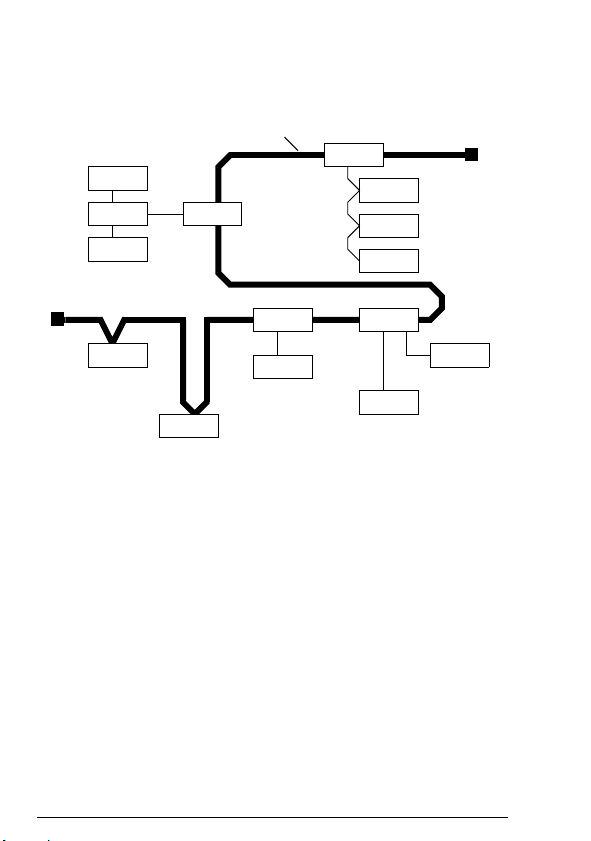
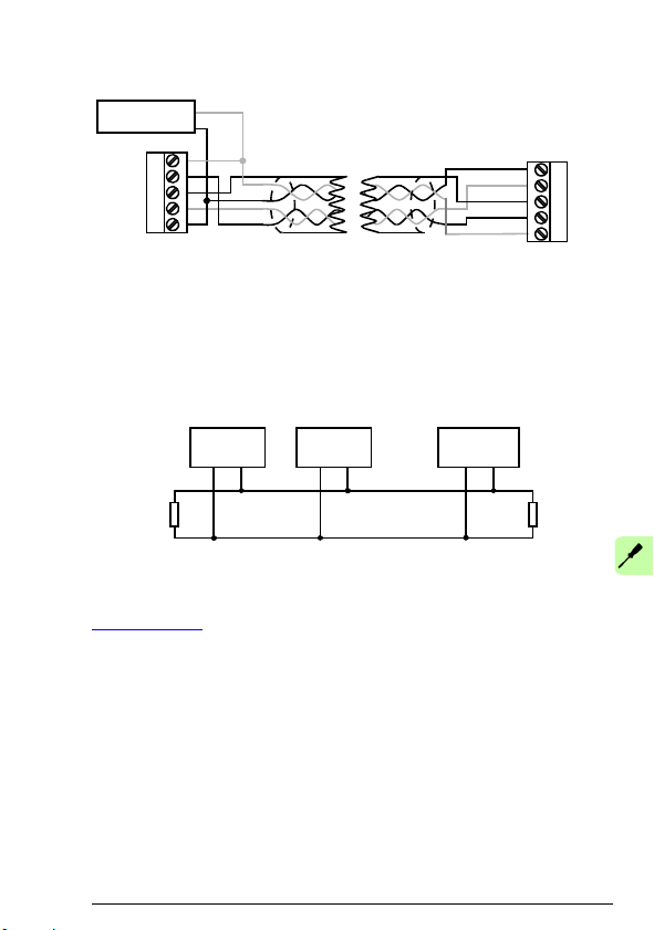
DeviceNet network
The DeviceNet network has a linear bus topology. Terminating
resistors are required on each end of the trunk line. Drop lines as
long as 6 metres (20 feet) each are permitted, allowing one or
more nodes to be attached. DeviceNet allows branching structures
only on drop lines.
The maximum length of the trunk cable depends on the data rate
and on the type of the cable used (see chapter Technical data).
Page 24
24 Overview of the DeviceNet network and the FDNA-01 module
Node
Node
Node
Node
Node
Tap
Tap
TapTap
Node
Node
Node
Node
Node
Node
Trunk li ne
Terminating
Resistor
Drop line
Example topology of the DeviceNet link
An example of an allowable topology is shown below.
Page 25

Overview of the DeviceNet network and the FDNA-01 module 25
FDNA-01 DeviceNet adapter module
The FDNA-01 DeviceNet Adapter module is an optional device for
ABB drives. It enables the connection of the drive to a DeviceNet
network. The drive is considered a slave in the DeviceNet network.
Through the adapter module you can:
• give control commands to the drive (for example, Start, Stop,
Run enable)
• feed a motor speed or torque reference to the drive
• give the actual value or reference of the process to the PID
controller of the drive
• read status information and actual values from the drive
• change drive parameter values
• reset a drive fault.
The adapter module acts as a class 2 slave only with predefined
master-slave connection set services. These include the explicit
messaging, the poll-response service and the change of state/
cyclic service. The DeviceNet commands and services supported
by the adapter module are described in chapter Communication
protocol.
The adapter module is mounted into an option slot on the motor
control board of the drive. See the drive manuals for the module
placement options.
Page 26
26 Overview of the DeviceNet network and the FDNA-01 module
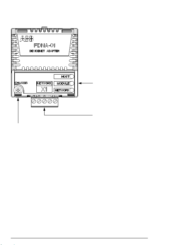
Diagnostic LEDs
(see chapter Diagnostics)
Bus connector X1
(see chapter Electrical
installation)
Mounting screw
Layout of the adapter module
Page 27
Mechanical installation 27
4
Mechanical installation
What this chapter contains
This chapter contains a delivery checklist and instructions on
mounting the adapter module.
WARNING! Follow the safety instructions given in this
manual and the drive documentation.
Delivery check
The option package for the adapter module contains:
• DeviceNet adapter module, type FDNA-01
• this manual.
Page 28

28 Mechanical installation
Mounting the adapter module
The adapter module is to be inserted into its specific position in the
drive. The module is held in place with plastic pins and one screw.
The screw also provides the electrical connection between the
module and drive frame for cable shield termination.
When the module is installed, the signal and power connection to
the drive is made through a 20-pin connector. (All drives do not use
all the available signals so the connector on the drive may have
fewer pins.)
Mounting procedure:
1. Insert the module carefully into its position on the drive.
2. Fasten the screw.
Note: It is essential to install the screw properly to fulfill the EMC
requirements and to ensure the proper operation of the module.
For more information on mounting, see the drive manuals.
Page 29
Electrical installation 29
5
Electrical installation
What this chapter contains
This chapter contains:
• general cabling instructions
• instructions on connecting the module to the DeviceNet
network
• instructions on switching on the bus termination.
WARNING! Before installation, switch off the drive power
supply. Wait five minutes to ensure that the capacitor bank
of the drive is discharged. Switch off all dangerous
voltages connected from external control circuits to the inputs and
outputs of the drive.
General cabling instructions
• Arrange the bus cables as far away from the motor cables as
possible.
• Avoid parallel runs.
• Use bushings at cable entries.
Page 30
30 Electrical installation
5
3
Male micro-style
SHLD
CAN_L
CAN_H
V-
1234
connector
4
1
2
X1
0 V
+24 V
Network
power supply
4
5
3
1
2
FDNA
5
V+
V+
3
2
Male mini-style
4
5
3
1
2
connector
4
51
0 V
+24 V
Network
power supply
SHLD
CAN_L
CAN_H
V-
1234
X1
FDNA
5
Connecting the module to the DeviceNet network
Connect the bus cable to terminal block X1 on the adapter module.
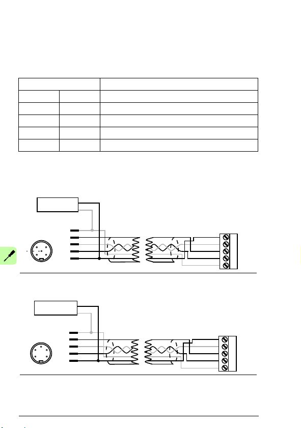
Terminal block description
X1 Description
1 V- Network power supply ground (0V DC)
2 CAN_L CAN_L bus line
3 SHLD Network cable shield
4 CAN_H CAN_H bus line
5 V+ Network power supply source (24V DC)
Connection examples
5-pin micro-style connector:
5-pin mini-style connector:
Page 31
Electrical installation 31
4321 5
SHLD
CAN_L
CAN_H
V-
1234
X1
FDNA
5
V+
0 V
+24 V
Network
power supply
Node 1 Node n
121
Ω
CAN_H
CAN_L
Scanner
121
Ω
1%
Metal Film
1/4 W
1%
Metal Film
1/4 W
…
Standard open-style screw connector:
Switching on the bus termination
The adapter module does not provide bus termination. The
DeviceNet network should be terminated at both ends of the trunk
cable with a 121 ohm, ¼ W, 1% metal film resistor. Connect the
resistor between the two signal wires (CAN_H, CAN_L) on the
DeviceNet cable, as shown in the figure below.
Further information on the DeviceNet protocol is available at
www.odva.org
.
Page 32

32 Electrical installation
Page 33

Start-up 33
6
Start-up
What this chapter contains
This chapter contains:
• information on configuring the drive for operation with the
adapter module
• drive-specific instructions on starting up the drive with the
adapter module
• examples of configuring the master station for communication
with the adapter module.
WARNING! Follow the safety instructions given in this
manual and the drive documentation.
Page 34

34 Start-up
Drive configuration
The following information applies to all drive types compatible with
the adapter module, unless otherwise stated.
DeviceNet connection configuration
After the adapter module has been mechanically and electrically
installed according to the instructions in chapters Mechanical
installation and Electrical installation, the drive must be prepared
for communication with the module.
The detailed procedure of activating the module for DeviceNet
communication with the drive depends on the drive type. Normally,
a parameter must be adjusted to activate the communication. See
the drive-specific start-up procedures starting on page 49.
Once communication between the drive and the adapter module
has been established, several configuration parameters are copied
to the drive. These parameters are shown in the tables below and
must be checked first and adjusted where necessary.
Note: Not all drives display descriptive names for the configuration
parameters. To help you identify the parameters in different drives,
the names displayed by each drive are given in grey boxes in the
tables.
Note: The new settings take effect only when the adapter module
is powered up the next time or when the fieldbus adapter refresh
parameter is activated.
Note: If communication between the adapter module and
DeviceNet master is established, changes to the configuration
parameters can be done also through Fieldbus configuration object
91h.
Page 35

Start-up 35
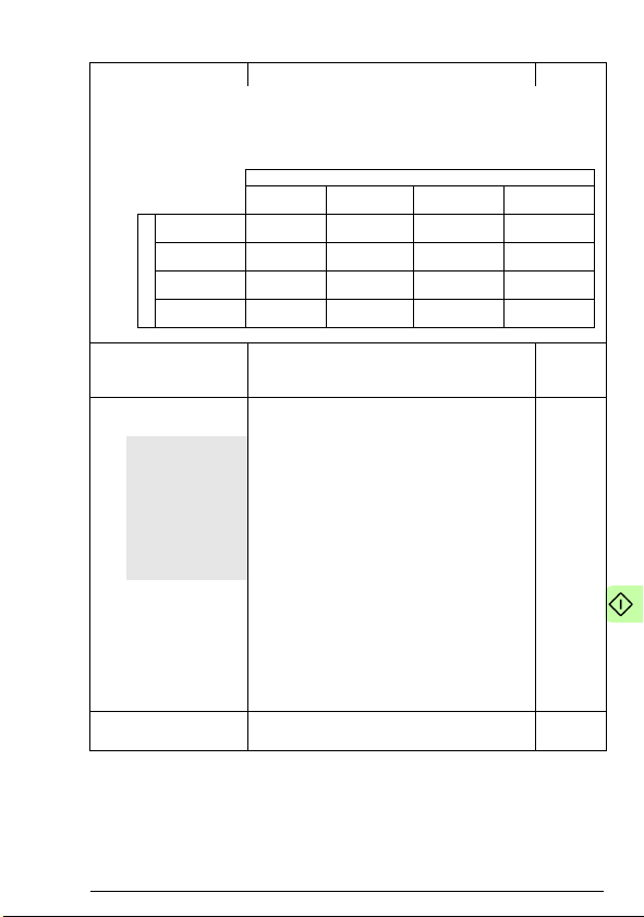
FDNA-01 configuration parameters – group A (group 1)
Note: The actual parameter group number depends on the drive
type. Group A (group 1) corresponds to:
• parameter group 51 in ACS355, ACSM1, ACS850 and
ACQ810
• parameter group 51 in ACS880 if the adapter is installed as
fieldbus adapter A or group 54 if the adapter is installed as
fieldbus adapter B.
No. Name/Value Description Default
01 FBA TYPE Read-only. Shows the fieldbus adapter type as
02 MAC ID Defines the MAC ID number for the drive the
ACS355:
FB PAR 2
ACSM1:
FBA PAR2
ACS850/ACQ810:
FBA par2
ACS880:
MAC ID
0…63 MAC ID
03 BAUD RATE Read-only. Indicates the detected
ACS355:
FB PAR 3
ACSM1:
FBA PAR3
ACS850/ACQ810:
FBA par3
ACS880:
Baud rate
0 = 125 kbit/s Communication speed is 125 kbit/s.
1 = 250 kbit/s Communication speed is 250 kbit/s.
2 = 500 kbit/s Communication speed is 500 kbit/s.
detected by the drive. Value cannot be adjusted
by the user.
If the value is 0 = None, the communication
between the drive and the module has not been
established.
adapter module is connected to. Each device
on the DeviceNet network must have a unique
MAC ID number.
communication speed in kbit/s.
1 = DeviceNet
63
0 = 125
kbit/s
Page 36

36 Start-up
No. Name/Value Description Default
04 DRIVE PROFILE Defines the communication used between the
ACS355:
FB PAR 4
ACSM1:
FBA PAR4
ACS850/ACQ810:
FBA par4
ACS880:
Drive profile
0 = Native prof Native profile of the drive selected
05 ODVA STOP
FUNC
ACS355:
FB PAR 5
ACSM1:
FBA PAR5
ACS850/ACQ810:
FBA par5
ACS880:
ODVA stop func
0 = Ramp stop Motor decelerates along the active deceleration
1 = Coast stop Motor comes to a stop by coasting.
module and the drive (not fie ldbus and module).
If a drive supports more than one drive profile,
this parameter is used to select the preferred
profile. Presently, to use the ODVA and ABB
Drives profiles, the drive must support a native
profile (eg, DCU or FBA). Transparent16 and
Transparent32 profiles may be used with any
drive profile.
Used with the ODVA AC/DC drive profile.
Determines how the motor is stopped when a
stop command is received via DeviceNet.
ramp.
0 =
Native
prof
0 = Ramp
stop
Page 37

Start-up 37
Name Output
instance
Input
instance
Default
input
size
(bytes)
Profile
Basic speed control 20 70 4 ODVA AC/DC drive
Extended speed
control
21 71 4 ODVA AC/DC drive
Basic speed and
torque control
22 72 6 ODVA AC/DC drive
Extended speed and
torque control
23 73 6 ODVA AC/DC drive
Basic speed control
plus drive parameters
120 170 24 ODVA AC/DC drive
Extended speed
control plus drive
parameters
121 171 24 ODVA AC/DC drive
Basic speed and
torque control plus
drive parameters
122 172 26 ODVA AC/DC drive
Extended speed and
torque control plus
drive parameters
123 173 26 ODVA AC/DC drive
ABB Drives profile
with set speed
801 851 4 ABB Drives
ABB Drives profile
with set speed and
set torque
802 852 6 ABB Drives
(continued)
No. Name/Value Description Default
06 OUTPUT
INSTANCE
ACS355:
FB PAR 6
ACSM1:
FBA PAR6
ACS850/ACQ810:
FBA par6
ACS880:
Output instance
Configures the output assembly instances used
by the adapter module. Tables below list the
supported assemblies and allowed
combinations. For the descriptions of the
assembly instances, see section Assembly
objects on page 98.
20
Page 38

38 Start-up
Name Output
instance
Input
instance
Default
input
size
(bytes)
Profile
(continued)
ABB Drives profile
with set speed plus
drive parameters
901 951 24 ABB Drives
ABB Drives profile
with set speed and
set torque plus drive
parameters
902 952 26 ABB Drives
ABB Drives profile
with set speed plus
drive parameters
901 951 24 ABB Drives
Transparent16 with
one
811 861 4 Transparent16
Transparent16 with
two
812 862 6 Transparent16
Transparent16 with
one plus drive
parameters
911 961 24 Transparent16
Transparent16 with
two plus drive
parameters
912 962 26 Transparent16
Transparent32 with
one
821 871 8 Transparent32
Transparent32 with
two
822 872 12 Transparent32
Transparent32 with
one plus drive
parameters
921 971 28 Transparent32
Transparent32 with
two plus drive
parameters
922 972 32 Transparent32
No. Name/Value Description Default
Page 39
Input
ODVA
(70-73; 170-173)
ABB DRIVES
(851-852; 951-952
TRANSPARENT16
(861-862; 961-962)
TRANSPARENT32
(871-872; 971-972)
Output
ODVA
(20-23; 120-123)
x
ABB DRIVES
(801-802; 901-902)
x
TRANSPARENT16
(811-812; 911-912)
x
TRANSPARENT32
(821-822; 921-922)
x
Start-up 39
No. Name/Value Description Default
Note: With ACSM1, ACQ810, ACS850 and ACS880, when using the ODVA
AC/DC drive or ABB Drives profile, make sure that drive parameter 50.04 FBA
REF MODESEL is set to SPEED. With ACSM1, ACS850 and ACS880, make
sure that 50.05 FBA REF2 MODESEL is set to TORQUE.
For alternative values, see column Output
instance in the table describing parameter 06
OUTPUT INSTANCE.
07 OUTPUT NUM
PAR S
ACS355:
FB PAR 7
ACSM1:
FBA PAR7
ACS850/ACQ810:
FBA par7
ACS880:
Output num pars
1…10 Number or drive parameter values to be
Some assembly instances support transferring
drive parameter values between the I/O
scanner and drive. Parameters 07 OUTPUT
NUM PARS and 09 INPUT NUM PARS specify
how many drive parameter values should be
included in the respective assembly instance.
Changing the numbers of the drive parameters
to values other than the defaults also changes
the lengths of the associated assembly
instances. This requires manual changes to
either the EDS file or I/O scanner configuration.
Before changing these parameters, consult
Appendix A – Varying the number of drive
parameters.
Note: This parameter is only used when the
output assembly instance is 120, 121, 122, 123,
901, 902, 911, 912, 921, 922. It must always be
set to the default, 10, except as described in
Appendix A – Varying the number of drive
parameters
included in the assembly instance
10
Page 40

40 Start-up
No. Name/Value Description Default
08 INPUT INSTANCE Configures the input assembly instances used
ACS355:
FB PAR 9
ACSM1:
FBA PAR9
ACS850/ACQ810:
FBA par9
ACS880:
Input instance
09 INPUT NUM
PAR S
ACS355:
FB PAR 9
ACSM1:
FBA PAR9
ACS850/ACQ810:
FBA par9
ACS880:
Input num pars
1…10 Number or drive parameter values to be
by the adapter module. See parameter 06
OUTPUT INSTANCE.
For alternative values, see parameter 06
OUTPUT INSTANCE.
See parameter 07 OUTPUT NUM PARS.
Note: This parameter is only used when the
input assembly instance is 170, 171 , 172, 173,
951, 952, 961, 962, 971, 972. It must always be
set to the default, 10, except as described in
Appendix A – Varying the number of drive
parameters.
included in the assembly instance
70
10
Page 41

Start-up 41
ODVA speed scale value1)Speed scale value of
drive parameter
2)
Unit
-5 123 32 RPM
-4 124 16 RPM
-3 125 8 RPM
-2 126 4 RPM
-1 127 2 RPM
0 (default) 128 1 RPM
1 129 0.5 RPM
2 130 0.25 RPM
3 131 0.125 RPM
4 132 0.06 25 RPM
5 133 0.03 125 RPM
1)
Use the ODVA speed scale value when reading/writing parameter ODVA
SPEED SCALE via AC/DC-drive object, class 2Ah. When written via the
AC/DC drive object, the new value takes effect immediately.
2)
Use the speed scale value of the drive parameter when reading/writing
parameter ODVA SPEED SCALE via the d rive control panel, Drive parameter
object, Class 90h and Fieldbus configuration object 91h. When written via
these methods, the new value takes effect after the drive is repowered or a
“Fieldbus Adapter Parameter refresh” is given.
No. Name/Value Description Default
10 ODVA SPEED
SCALE
ACS355:
FB PAR 10
ACSM1:
FBA PAR10
ACS850/ACQ810:
FBA par10
ACS880:
ODVA speed scale
Defines the speed scale in the ODVA AC/DC
drive profile. Units of reference and actual
speeds for the ODVA AC/DC drive profile are
given by the formula below. No effect on the
ABB Drives profiles.
Note: While a wide range of resolutions may be
configured, the actual performance is limited to
the performance capabilities of the drive.
Speed unit = RPM X 2
Table below shows how the values of drive
parameter ODVA SPEED SCALE correspond
to the ODVA Speed Scale units.
(-1 X ODVA speed scale value)
128
123…133 Speed scale value of the drive parameter
Page 42

42 Start-up
ODVA torque scale value1)Torque scale value of
drive parameter
2)
Unit
-5 123 32 N·m
-4 124 16 N·m
-3 125 8 N·m
-2 126 4 N·m
-1 127 2 N·m
0 (default) 128 1 N·m
1 129 0.5 N·m
2 130 0.25 N·m
3 131 0.125 N·m
4 132 0.0625 N·m
5 133 0.03125 N·m
1)
Use the ODVA torque scale value when reading/writing parameter ODVA
TORQUE SCALE via AC/DC-drive object, class 2Ah. When written via the
AC/DC drive object, the new value takes effect immediately.
2)
Use the torque scale value of the drive parameter when reading/writing
parameter ODVA TORQUE SCALE via the drive control panel, Drive
parameter object, Class 90h and Fieldbus configuration object 91h. When
written via these methods, the new value takes effect after the drive is
repowered or a “Fieldbus Adapter Parameter refresh” is given.
No. Name/Value Description Default
11 ODVA TORQUE
SCALE
ACS355:
FB PAR 11
ACSM1:
FBA PAR11
ACS850/ACQ810:
FBA par11
ACS880:
ODVA torque
scale
Defines the torque scale in the ODVA AC/DC
drive profile. Units of reference and actual
torques for the ODVA AC/DC drive profile are
given by the formula below. No effect on the
ABB Drives profiles.
Note: While a wide range of resolutions may be
configured, the actual performance is limited to
the performance capabilities of the drive.
(N·m = Newton x Meter)
Torque unit = N·m x 2
Table below shows how the values of drive
parameter ODVA TORQUE SCALE correspond
to the ODVA Torque Scale units.
(-1 X ODVA torque scale)
128
123…133 Torque scale value of the drive parameter
12
Reserved Not used by the adapter module. N/A
…
25
Page 43
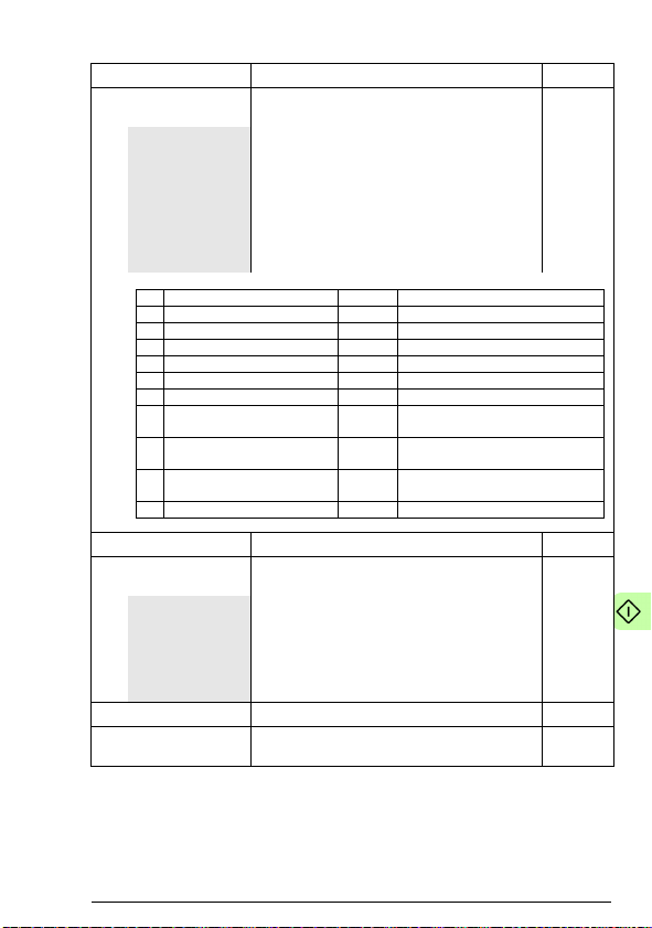
No. Name/Value Description Default
Bit Name Value Description
1 DUP_MAC_ERROR 0x0001 Duplicate MAC ID error
2 RX_QUEUE_OVERRUN 0x0002 Message receive queue is full.
3 TX_QUEUE_OVERRUN 0x0004 Message transmit queue is full.
4 IO_SEND_ERROR 0x0008 Transmitting I/O data has failed.
5 CAN_BUS_OFF 0x0010 Bus-off is detected.
6 CAN_OVERRUN 0x0020 CAN message was lost.
7 DNS_RESET 0x0040 DeviceNet driver of the module is
reset.
8 DNS_BUS_SENSE_ERROR 0x0080 No voltage detected in the
network.
9 DNS_SWITCH_ERROR 0x0100 DeviceNet driver reset failed due
to an invalid MAC ID or baud rate.
13 SYS_FILE_ERR 0x1000 Initialization with the drive failed.
26 UNRECOVER-
ABLE ERROR
ACS355:
FB PAR 26
ACSM1:
FBA PAR26
ACS850/ACQ810:
FBA par26
ACS880:
Unrecover. error
0…65535 Active unrecoverable errors
27 FBA PAR
REFRESH
ACS355/ACSM1:
FBA PAR
REFRESH
ACS850/ACQ810/
ACS880:
FBA par refresh
0 = Done Refreshing done
1 =
Refresh/Configure
Read-only. Shows information about the cause
of an unrecoverable error in the ad apter
module. Bit field parameter, that is, several
status bits can be set at a time. Value 0
indicates that there are no errors.
Validates any changed adapter module
configuration parameter settings. After
refreshing, the value reverts automatically to
0 = Done.
Note: This parameter cannot be changed while
the drive is running.
Refreshing
Start-up 43
0
0 = Done
Page 44

44 Start-up
No. Name/Value Description Default
28 PAR TABLE VER Read-only. Displays the parameter table
ACS355:
FILE CPI FW REV
ACSM1:
PAR TABLE VER
ACS850/ACQ810/
ACS880:
Par table ver
0x0000…0xFFFF Parameter table revision
29 DRIVE TYPE
CODE
ACS355:
FILE CONFIG ID
ACSM1:
DRIVE TYPE
CODE
ACS850/ACQ810/
ACS880:
Drive type code
0…65535 Drive type code of the fieldbus adapter module
30 MAPPING FILE
VER
ACS355:
FILE CONFIG
REV
ACSM1:
MAPPING FILE
VER
ACS850/ACQ810/
ACS880:
Mapping file ver
0…65535 Mapping file revision
revision of the fieldbus adapter module
mapping file stored in the memory of the drive.
In format xyz, where
x = major revision number
y = minor revision number
z = correction number
OR
in format axyz, where
a = major revision number
xy = minor revision numbers
z = correction number or letter.
Read-only. Displays the drive type code of the
fieldbus adapter module mapping file stored in
the memory of the drive.
mapping file
Read-only. Displays the fieldbus adapter
module mapping file revision stored in the
memory of the drive in decimal format.
Example: 0x107 = revision 1.07.
N/A
N/A
N/A
Page 45

Start-up 45
No. Name/Value Description Default
31 D2FBA COMM
STA
ACS355:
FBA STATUS
ACSM1:
D2FBA COMM
STA
ACS850/ACQ810/
ACS880:
D2FBA comm sta
0 = Idle Adapter is not configured.
1 = Exec.init Adapter is initializing.
2 = Time out Time-out has occurred in the communication
3 = Conf.err Adapter configuration error: Major or minor
4 = Off-line Adapter is off-line.
5 = On-line Adapter is on-line.
6 = Reset Adapter is performing a hardware reset.
32 FBA COMM SW
VER
ACS355:
FBA CPI FW REV
ACSM1:
FBA COMM SW
VER
ACS850/ACQ810/
ACS880:
FBA comm SW
ver
0x0000…0xFFFF Common program version of the adapter
Read-only. Displays the status of the fieldbus
adapter module communication.
Note: The value names may vary by drive.
between the adapter and the dr ive.
revision code of the common program revision
in the fieldbus adapter module is not the
revision required by the module or mapping file
upload has failed more than three times.
Read-only. Displays the common program
revision of the adapter module in format axyz,
where:
a = major revision number
xy = minor revision numbers
z = correction number or letter.
Example: 190A = revision 1.90A
module
0 = Idle
N/A
Page 46

46 Start-up
No. Name/Value Description Default
33 FBA APPL SW
VER
ACS355:
FBA CPI APPL
REV
ACSM1:
FBA COMM APPL
VER
ACS850/ACQ810/
ACS880:
FBA appl SW ver
0x0000…0xFFFF Application program revision of the adapter
Read-only. Displays the application program
revision of the adapter module in format axyz,
where:
a = major revision number
xy = minor revision numbers
z = correction number or letter.
Example: 190A = revision 1.90A
module
N/A
Page 47

Start-up 47
0Not used
1…99 Virtual address area of drive control.
Not used with the FDNA-01 module.
101…
9999
Parameter area of the drive
FDNA-01 configuration parameters – group B (group 2)
Note: The actual parameter group number depends on the drive
type. Group B (group 2) corresponds to:
• parameter group 55 in ACS355
• parameter group 53 in ACSM1, ACS850 and ACQ810
• parameter group 53 in ACS880 if the adapter is installed as
fieldbus adapter A or group 56 if the adapter is installed as
fieldbus adapter B.
No.1)Name/Value Description Default
01 DATA OUT 1
(master to drive)
ACS355:
FBA DATA OUT 1
ACSM1:
FBA DATA OUT1
ACS850/ACQ810/
ACS880:
FBA data out1
0 Not used
101…9999 Parameter index with format xxyy, where xx is
02…10DATA OUT 2…
DATA OUT 10
1)
The number of parameters in this group may vary by drive type and drive firmware.
In the output assembly instances that include
drive parameters, this parameter specifies
which parameter’s value is placed in location
DATA OUT 1 value received by the drive from
the DeviceNet network. Content is defined by a
decimal number in the range of 0 to 9999 as
follows:
Note: The FDNA-01 configuration parameters
are 16-bit parameters. If the mapped parameter
is a 32-bit parameter, it automatically reserves
two consecutive parameters. For example,
mapping a 32-bit parameter to parameter no. 1
also reserves parameter no. 2.
the parameter group number (1…99) and yy is
the parameter number index within that group
(01…99).
See parameter DATA OUT 1.0
0
Page 48

48 Start-up
0 Not used
1…99 Virtual address area of drive control.
Not used with the FDNA-01 module.
101…
9999
Parameter area of the drive
FDNA-01 configuration parameters – group C (group 3)
Note: The actual parameter group number depends on the drive
type. Group C (group 3) corresponds to:
• parameter group 54 in ACS355
• parameter group 52 in ACSM1, ACS850 and ACQ810
• parameter group 52 in ACS880 if the adapter is installed as
fieldbus adapter A or group 55 if the adapter is installed as
fieldbus adapter B.
No.1)Name/Value Description Default
01 DATA IN 1
(drive to master)
ACS355:
FBA DATA IN 1
ACSM1:
FBA DATA IN1
ACS850/ACQ810/
ACS880:
FBA data in1
0 Not used
101…9999 Parameter index with format xxyy, where xx is
02…10DATA IN 2…
DATA IN 10
1)
The number of parameters in this group may vary by drive type and drive firmware.
In input assembly instances that include drive
parameters, this parameter specifies which
parameter’s value is placed in location DATA IN
1 value sent by the drive to the DeviceNet
network. Content is defined by a decimal
number in the range of 0 to 9999 as follows:
Note: The FDNA-01 configuration parameters
are 16-bit parameters. If the mapped parameter
is a 32-bit parameter, it automatically reserves
two consecutive parameters. For example,
mapping a 32-bit parameter to parameter no. 1
also reserves parameter no. 2.
the parameter group number (1…99) and yy is
the parameter number index within that group
(01…99).
See parameter DATA IN 1.0
0
Page 49

Start-up 49
Control locations
ABB drives can receive control information from multiple sources
including digital inputs, analog inputs, the drive control panel and a
communication module (for example, the adapter module). ABB
drives allow the user to separately determine the source for each
type of control information (Start, Stop, Direction, Reference, Fault
Reset, and so on).
To give the fieldbus master station the most complete control over
the drive, the communication module must be selected as the
source for this information. The parameter setting examples below
contain the drive control parameters needed in the examples. For
a complete parameter list, see the drive documentation.
Starting up ACS355 drives
1. Power up the drive.
2. Enable the communication between the adapter module and
the drive by setting parameter 9802 COMM PROT SEL to EXT
FBA.
3. Set the FDNA-01 configuration parameters in parameter group
51.
At the minimum, set the required number in parameter 5102
MAC ID and the required baud rate in 5103 BAUD RATE. In
addition, select the communication profile in 5104 DRIVE
PROFILE. With the ODVA AC/DC drive profile select the way
in which the motor is stopped in 5105 ODVA STOP FUNC.
4. Define the process data transferred to and from the drive in
FDNA-01 parameter groups 54 and 55.
Note: If communication between the FDNA-01 and DeviceNet
master is established, changes to the configuration parameters
can be done also through Fieldbus configuration object 91h.
5. Validate the settings made in parameter group 51 by setting
parameter 5127 FBA PAR REFRESH to REFRESH.
Page 50

50 Start-up
6. Set the relevant drive control parameters to control the drive
according to the application. Examples of appropriate values
are shown in the tables below.
Parameter setting examples – ACS355
ABB Drives profile
This example shows how to configure the ACS355 drive to use the
ABB Drives profile with set speed and set torque plus drive
parameters assembly.
The used I/O assembly instances are 902 and 952.
The table below gives the recommended drive parameter settings.
Drive parameter Setting for
9802 COMM PROT SEL 4 = EXT FBA Enables communication between
5101 FBA TYPE DEVICENET
5102 FB PAR 2
(MAC ID)
5103 FB PAR 3
(BAUD RATE)
5104 FB PAR 4
(DRIVE PROFILE)
5105 FB PAR 5
(ODVA STOP FUNC)
5106 FB PAR 6
(OUTPUT INSTANCE)
5107 FB PAR 7
(OUTPUT NUM PARS)
5108 FB PAR 8
(INPUT INSTANCE)
ACS355 drives
2 Defines the MAC ID number of the
0 (= 125 kbit/s) Sets the baud rate for the
0 (= DCU Profile) Selects the profile used in the
0 (= Ramp) Motor decelerates along the active
902 Selects the ABB Drives profile with
10 Must always be set to 10, except as
952 Selects the ABB Drives profile with
Description
drive and adapter module.
1)
Displays the type of the adapter
module.
adapter module.
DeviceNet interface.
communication between drive and
adapter module.
deceleration ramp.
speed and torque plus drive
parameters output instance.
provided in Appendix A – Varying
the number of drive parameters.
speed and torque plus drive
parameters input instance.
Page 51

Start-up 51
Drive parameter Setting for
5109 FB PAR 9
(INPUT NUM PARS)
5110 FB PAR 10
(ODVA SPEED SCALE)
5111 FB PAR 11
(ODVA TORQUE SCALE)
5401 FBA DATA IN 1 104 Current
5402 FBA DATA IN 2 107 DC bus voltage
5403 FB DATA IN 3
…5410 DATA IN 10
5501 FBA DATA OUT 1 2205 Acceleration time 2
5502 FBA DATA OUT 2 2206 Deceleration time 2
5503 FB DATA OUT 3
…5510 DATA OUT 10
51.27 FBA PAR REFRESH 1 = REFRESH Validates the FDNA-01
1001 EXT1 COMMANDS 10 = COMM Selects the fieldbus interface as the
1003 DIRECTION 3 = REQUEST Allows control of rotation direction.
1103 REF1 SELECT 8 = COMM Selects the fieldbus reference 1 as
1604 FAULT RESET SEL 8 = COMM Selects the fieldbus interface as the
9904 MOTOR CTRL MODE 2 = VECTOR:
1002 EXT2 COMMANDS 10 = COMM Selects the fieldbus interface as the
1102 EXT1/EXT2 SEL 8 = COMM Enables external control location
1106 REF2 SELECT 8 = COMM Selects the fieldbus reference 2 as
ACS355 drives
10 Must always be set to 10, except as
128 Sets the scaling as 1 rpm for the
128 Sets the scaling as 1 Nm for the
0
0
TORQ
Description
provided in Appendix A – Varying
the number of drive parameters.
ODVA speed reference.
ODVA torque reference.
configuration parameter settings.
source of the start and stop
commands for external control
location 1.
the source for speed reference.
source for the fault reset signal.
Selects the vector control mode as
the motor control mode.
source of the start and stop
commands for external control
location 2.
1/2 selection through the fieldbus.
the source for torque reference.
Page 52

52 Start-up
Drive parameter Setting for
1601 RUN ENABLE 7 = COMM Selects the fieldbus interface as the
1)
Read-only or automatically detected/set
The start sequence for the parameter example above is given
below.
ACS355 drives
Description
source for the inverted Run enable
signal (Run disable).
Control word:
• 47Eh (1150 decimal) –> READY TO SWITCH ON
• 47Fh (1151 decimal) –> OPERATING (Speed mode)
or
C7Fh (3199 decimal) –> OPERATING (Torque mode).
ODVA AC/DC drive profile
The following example shows how to configure the ACS355 drive
to use the Extended speed and torque control assembly of the
ODVA AC/DC drive profile.
The used I/O assembly instances are 23 and 73.
The table below gives the recommended drive parameter settings.
Drive parameter Setting for
9802 COMM PROT SEL 4 = EXT FBA Enables communication between
5101 FBA TYPE DEVICENET
5102 FB PAR 2
(MAC ID)
5103 FB PAR 3
(BAUD RATE)
5104 FB PAR 4
(DRIVE PROFILE)
5105 FB PAR 5
(ODVA STOP FUNC)
ACS355 drives
5 Defines the MAC ID number of the
0 (= 125 kbit/s) Sets the baud rate for the
0 (= DCU Profile) Selects the profile used in the
0 (= Ramp) Motor decelerates along the active
Description
drive and adapter module.
1)
Displays the type of the adapter
module.
adapter module.
DeviceNet interface.
communication between drive and
adapter module.
deceleration ramp.
Page 53

Start-up 53
Drive parameter Setting for
5106 FB PAR 6
(OUTPUT INSTANCE)
5108 FB PAR 8
(INPUT INSTANCE)
5110 FB PAR 10
(ODVA SPEED SCALE)
5111 FB PAR 11
(ODVA TORQUE SCALE)
ACS355 drives
23 Selects the ODVA extended speed
73 Selects the ODVA extended speed
128 Sets the scaling as 1 rpm for the
128 Sets the scaling as 1 Nm for the
51.27 FBA PAR REFRESH 1 = REFRESH Validates the FDNA-01
1001 EXT1 COMMANDS 10 = COMM Selects the fieldbus interface as
Description
and torque control output instance.
and torque control input instance.
ODVA speed reference.
ODVA torque reference.
configuration parameter settings.
the source of the start and stop
commands for external control
location 1.
1003 DIRECTION 3 = REQUEST Allows control of rotation direction.
1103 REF1 SELECT 8 = COMM Selects the fieldbus reference 1 as
1604 FAULT RESET SEL 8 = COMM Selects the fieldbus interface as
9904 MOTOR CTRL MODE 2 = VECTOR:
TORQ
1002 EXT2 COMMANDS 10 = COMM Selects the fieldbus interface as
1102 EXT1/EXT2 SEL 1 = DI1 Selects digital input DI1 as the
1106 REF2 SELECT 8 = COMM Selects the fieldbus reference 2 as
1601 RUN ENABLE 7 = COMM Selects the fieldbus interface as
1)
Read-only or automatically detected/set
the source for speed reference.
the source for the fault reset
signal.
Selects the vector control mode as
the motor control mode.
the source of the start and stop
commands for external control
location 2.
source for the external control
location EXT1/EXT2 selection.
the source for torque reference.
the source for the inverted Run
enable signal (Run disable).
Page 54

54 Start-up
Note: In this example, digital input DI1 has been configured to
control whether to use the speed or torque control mode.
The start sequence for the parameter example above is given
below.
Control word:
• 0h (0 decimal) –> READY
• 1h (1 decimal) –> ENABLED (Running forward)
• 2h (2 decimal) –> ENABLED (Running reverse)
Starting up ACSM1 drives
1. Power up the drive.
2. Enable the communication between the adapter module and
the drive by setting parameter 50.01 FBA ENABLE to Enable.
3. Ensure that 50.04 FBA REF1 MODESEL is set to Speed and
50.05 FBA REF2 MODESEL is set to Torque.
4. Set the FDNA-01 configuration parameters in parameter group
51.
5. Define the process data transferred to and from the drive in
FDNA-01 parameter groups 52 and 53.
Note: If communication between the FDNA-01 and DeviceNet
master is established, changes to the configuration parameters
can be done also through Fieldbus configuration object 91h.
6. Validate the settings made in parameter groups 51, 52 and 53
by setting parameter 51.27 FBA PAR REFRESH to REFRESH.
7. Set the relevant drive control parameters to control the drive
according to the application. Examples of appropriate values
are shown in the tables below.
Page 55

Start-up 55
Parameter setting examples – ACSM1
ABB Drives profile
The following example shows how to configure the ACSM1 drive to
use the ABB Drives profile.
The used I/O assembly instances are 902 and 952.
The table below gives the recommended drive parameter settings.
Drive parameter Setting for
50.01 FBA ENABLE 1 = Enable Enables communication between
50.04 FBA REF1
MODESEL
50.05 FBA REF2
MODESEL
51.01 FBA TYPE DEVICENET1)Displays the type of the adapter
51.02 FBA PAR2
(MAC ID)
51.03 FBA PAR3
(BAUD RATE)
51.06 FBA PAR6
(OUTPUT INSTANCE)
51.07 FBA PAR7
(OUTPUT NUM PARS)
51.08 FBA PAR8
(INPUT INSTANCE)
51.09 FBA PAR9
(INPUT NUM PARS)
52.01 FBA DATA IN1 117 Motor temp
52.02 FBA DATA IN2 104 Motor current - MSW
52.03 FBA DATA IN3 0 Motor current - LSW
52.04 FBA DATA IN4 107 DC voltage - MSW
ACSM1 drives
Speed Selects speed as the adapter
Torque Selects torque as the adapter
6 Defines the MAC ID number of the
0 (= 125 kbit/s) Sets the baud rate for the DeviceNet
902 Selects the ABB Drives profile with
10 Must always be set to 10, except as
952 Selects the ABB Drives profile with
10 Must always be set to 10, except as
Description
drive and adapter module.
module REF1 type.
module REF2 type.
module.
adapter module.
interface.
speed and torque plus drive
parameters output instance.
provided in Appendix A – Varying
the number of drive parameters.
speed and torque plus drive
parameters input instance.
provided in Appendix A – Varying
the number of drive parameters.
Page 56

56 Start-up
Drive parameter Setting for
52.05 FBA DATA IN5 0 DC voltage - LSW
52.06 FBA DATA IN6 108 Encoder 1 speed - MSW
52.07 FBA DATA IN7 0 Encoder 1 speed - LSW
52.08 FBA DATA IN8…
52.10 FBA DATA IN10
53.01 FBA DATA OUT1 2503 Acceleration time - MSW
53.02 FBA DATA OUT2 0 Acceleration time - LSW
53.03 FBA DATA OUT3 2504 Deceleration time - MSW
53.04 FBA DATA OUT4 0 Deceleration time - LSW
53.05 FBA DATA OUT5 2408 Constant speed
53.06 FBA DATA OUT6 2410 Speed ref jog1
53.07 FBA DATA OUT7 2411 Speed ref jog2
53.08 FBA DATA OUT8…
53.10 FBA DATA OUT10
51.27 FBA PAR REFRESH 1 = REFRESH Validates the FDNA-01 configuration
10.01 EXT1 START FUNC 3 = FBA Selects the fieldbus interface as the
10.04 EXT2 START FUNC 3 = FBA Selects the fieldbus interface as the
24.01 SPEED REF1 SEL 3 = FBA REF1 Selects the fieldbus reference 1 as
32.01 TORQ REF1 SEL 4 = FBA REF2 Selects the fieldbus reference 2 as
34.02 EXT1 MODE 1/2SEL P. 2 . 1 2 . 1 5 =
34.03 EXT1 CTRL MODE1 1 = Speed Selects speed as the control mode
34.05 EXT2 CTRL MODE1 2 =Torque Selects torque as the control mode
ACSM1 drives
0
0
P.FBA MAIN
CW.15
Description
parameter settings.
source of the start and stop
commands for external control
location 1.
source of the start and stop
commands for external control
location 2.
the source for speed reference 1.
the source for torque reference 1.
Selects FBA Control word bit 15 as
the source for the external control
location EXT1/EXT2 selection.
for external control location 1.
for external control location 2.
Page 57

Start-up 57
Drive parameter Setting for
99.05 MOTOR CTRL
MODE
1)
Read-only or automatically detected/set
The start sequence for the parameter example above is given
below.
ACSM1 drives
0 = DTC Selects DTC as the motor control
Description
mode.
Control word:
• 47Eh (1150 decimal) –> READY TO SWITCH ON
• 47Fh (1151 decimal) –> OPERATING (Speed mode)
or
C7Fh (3199 decimal) –> OPERATING (Torque mode).
ODVA AC/DC drive profile
The following example shows how to configure the ACSM1 drive to
use the ODVA AC/DC drive profile.
The used I/O assembly instances are 23 and 73.
The table below gives the recommended drive parameter settings.
Drive parameter Setting for
50.01 FBA ENABLE 1 = Enable Enables communication between
50.04 FBA REF1
MODESEL
50.05 FBA REF2
MODESEL
51.01 FBA TYPE DEVICENET1Displays the type of the adapter
51.02 FBA PAR2
(MAC ID)
51.03 FBA PAR3
(BAUD RATE)
51.06 FBA PAR6
(OUTPUT INSTANCE)
ACSM1 drives
Speed Selects speed as the adapter
Torque Selects torque as the adapter
5 Defines the MAC ID number of the
0 (= 125 kbit/s) Sets the baud rate for the DeviceNet
23 Selects the ODVA extended speed
Description
drive and adapter module.
module REF1 type.
module REF2 type.
module.
adapter module.
interface.
and torque control output instance.
Page 58

58 Start-up
Drive parameter Setting for
51.08 FBA PAR8
(INPUT INSTANCE)
51.27 FBA PAR REFRESH 1 = REFRESH Validates the FDNA-01 configuration
10.01 EXT1 START FUNC 3 = FBA Selects the fieldbus interface as the
10.04 EXT2 START FUNC 3 = FBA Selects the fieldbus interface as the
24.01 SPEED REF1 SEL 3 = FBA REF1 Selects the fieldbus reference 1 as
32.01 TORQ REF1 SEL 4 = FBA REF2 Selects the fieldbus reference 2 as
34.01 EXT1/EXT2 SEL P. 2 . 1 . 0 = PI.DI
34.03 EXT1 CTRL MODE1 1 = Speed Selects speed as the control mode
34.05 EXT2 CTRL MODE1 2 =Torque Selects torque as the control mode
99.05 MOTOR CTRL
MODE
1)
Read-only or automatically detected/set
ACSM1 drives
73 Selects the ODVA extended speed
STATUS.0
0 = DTC Selects DTC as the motor control
Description
and torque control input instance.
parameter settings.
source of the start and stop
commands for external control
location 1.
source of the start and stop
commands for external control
location 2
the source for speed reference 1.
the source for torque reference 1.
Selects digital input DI1 as the
source for the external control
location EXT1/EXT2 selection.
for external control location 1.
for external control location 2.
mode.
Note: In this example, digital input DI1 has been configured to
control whether to use the speed or torque control mode.
The start sequence for the parameter example above is given
below.
Control word:
• 0h (0 decimal) –> READY
• 1h (1 decimal) –> ENABLED (Running forward)
• 2h (2 decimal) –> ENABLED (Running reverse)
Page 59

Start-up 59
Starting up ACS850 and ACQ810 drives
1. Power up the drive.
2. Enable the communication between the adapter module and
the drive by setting parameter 50.01 Fba enable to Enable.
3. Ensure that 50.04 Fb ref1 modesel is set to Speed (both
ACS850 and ACQ810) and 50.05 Fb ref2 modesel is set to
Torque (only ACS850).
4. Set the FDNA-01 configuration parameters in drive parameter
group 51.
5. Define the process data transferred to and from the drive in
FDNA-01 parameter groups 52 and 53.
Note: If communication between the FDNA-01 and DeviceNet
master is established, changes to the configuration parameters
can be done also through Fieldbus configuration object 91h.
6. Validate the settings made in parameter groups 51, 52 and 53
by setting parameter 51.27 FBA par refresh to Refresh.
7. Set the relevant drive control parameters to control the drive
according to the application. Examples of appropriate values
are shown in the tables below.
Page 60

60 Start-up
Parameter setting examples – ACS850 and ACQ810
ABB Drives profile
The following example shows how to configure the ACS850 or
ACQ810 drive to use the ABB Drives profile.
The used I/O assembly instances are 902 and 952.
The table below gives the recommended drive parameter settings.
Drive parameter Setting for
50.01 Fba enable 1 = Enable Enables communication between
50.04 Fb ref1 modesel Speed Selects speed as the adapter
50.05 Fb ref2 modesel Torque Selects torque as the adapter
51.01 Fba type DEVICENET
51.02 FBA par2
(MAC ID)
51.03 FBA par3
(BAUD RATE)
51.06 FBA par6
(OUTPUT INSTANCE)
51.07 FBA par7
(OUTPUT NUM PARS)
51.08 FBA par8
(INPUT INSTANCE)
51.09 FBA par9
(INPUT NUM PARS)
52.01 FBA data in1 123 Motor power
52.02 FBA data in2 0 Motor power - LSW
ACS850/ACQ810
drives
5 Defines the MAC ID number of the
0 (= 125 kbit/s) Sets the baud rate for the
902 Selects the ABB Drives profile with
10 Must always be set to 10, except as
952 Selects the ABB Drives profile with
10 Must always be set to 10, except as
Description
drive and adapter module.
module ref1 type.
module ref2 type (only with
ACS850).
1)
Displays the type of the adapter
module.
adapter module.
DeviceNet interface.
speed and torque plus drive
parameters output instance.
provided in Appendix A – Varying
the number of drive parameters.
speed and torque plus drive
parameters input instance.
provided in Appendix A – Varying
the number of drive parameters.
Page 61

Start-up 61
Drive parameter Setting for
52.03 FBA data in3 105 Motor current percent
52.04 FBA data in4 107 DC voltage
52.05 FBA data in5 0 DC voltage - LSW
52.06 FBA data in6 108 Encoder1 speed
52.07 FBA data in7 0 Encoder 1 speed - LSW
52.08 FBA data in8…
52.10 FBA data in10
53.01 FBA data out1 2204 Acc t ime 2
53.02 FBA data out2 0 Acceleration time 2 - LSW
53.03 FBA data out3 2205 Dec time 2
53.04 FBA data out4 0 Deceleration time 2 - LSW
53.05 FBA data out5 2606 Con st speed1
53.06 FBA data out6 2607 Con st speed2
53.07 FBA data out7 2608 Con st speed3
53.08 FBA data out8…
53.10 FBA data out10
51.27 FBA par refresh 1 = Refresh Validates the FDNA-01
10.01 Ext1 start func FB Selects the fieldbus interface as the
10.04 Ext2 Start func 3 = FB Selects the fieldbus as the source
12.01 Ext1/Ext sel P.2.22.15 = P.FBA
12.03 Ext1 ctrl mode 1 = Speed Selects speed as the operating
ACS850/ACQ810
drives
0
0
main cw.15
Description
configuration parameter settings.
source of the start and stop
commands for external control
location 1.
for start and stop commands for
external control location EXT2 (only
with ACS850).
Selects FBA Control word bit 15 as
the source for external control
location EXT1/EXT2 selection (only
with ACS850).
mode for external control location
EXT1.
Page 62

62 Start-up
Drive parameter Setting for
12.05 Ext2 ctrl mode 2 = Torque Selects torque as the operating
16.15 Menu set sel
(ACS850)
16.21 Menu selection
(ACQ810)
21.01 Speed ref1 sel FB Selects the fieldbus reference 1 as
24.01 Torq ref1 sel FBA ref2 Selects fieldbus reference 2 as the
1)
Read-only or automatically detected/set
ACS850/ACQ810
drives
2 = Load long
(ACS850)
2 = Full (ACQ810)
Description
mode for external control location
EXT2 (only with ACS850).
Load long parameter list. All
parameters will be displayed.
the source for speed reference 1.
source of the torque reference 1
(only with ACS850).
The start sequence for the parameter example above is given
below.
Control word:
• 47Eh (1150 decimal) –> READY TO SWITCH ON
• 47Fh (1151 decimal) –> OPERATING (Speed mode)
or
C7Fh (3199 decimal) –> OPERATING (Torque mode in
ACS850).
Page 63
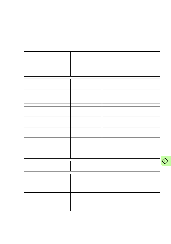
Start-up 63
ODVA AC/DC drive profile
The following example shows how to configure the ACS850 or
ACQ810 drive to use the ODVA AC/DC drive profile.
The used I/O assembly instances are 23 and 73.
The table below gives the recommended drive parameter settings.
Drive parameter Setting for
50.01 Fba enable 1 = Enable Enables communication between
50.04 Fb ref1 modesel Speed Selects speed as the adapter
50.05 Fb ref2 modesel Torque Selects torque as the adapter
51.01 FBA type DEVICENET1)Displays the type of the adapter
51.02 FBA par2
(MAC ID)
51.03 FBA par3
(BAUD RATE)
51.06 FBA par6
(OUTPUT INSTANCE)
51.08 FBA par8
(INPUT INSTANCE)
51.27 FBA par refresh 1 = Refresh Validates the FDNA-01
10.01 Ext1 start func 3 = FB Selects the fieldbus interface as the
10.04 Ext2 Start func 3 = FB Selects the fieldbus as the source
ACS850/ACQ810
drives
5 Defines the MAC ID number of the
0 (= 125 kbit/s) Sets the baud rate for the
23 Selects the ODVA AC/DC drive
73 Selects the ODVA AC/DC profile
Description
drive and adapter module.
module ref1 type.
module ref2 type (only with
ACS850).
module.
adapter module.
DeviceNet interface.
profile output instance.
input instance.
configuration parameter settings.
source of the start and stop
commands for external control
location 1.
for start and stop commands for
external control location EXT2 (only
with ACS850).
Page 64

64 Start-up
Drive parameter Setting for
12.01 Ext1/Ext2 sel DI1 Selects digital input DI1 as the
12.05 Ext2 ctrl mode 2 = Torque Selects torque as the operating
16.15 Menu set sel
(ACS850)
16.21 Menu selection
(ACQ810)
21.01 Speed ref1 sel FBA ref1 Selects the fieldbus reference 1 as
24.01 Torq ref1 sel FBA ref2 Selects fieldbus reference 2 as the
1)
Read-only or automatically detected/set
Note: For ACS850 in this example, digital input DI1 has been
configured to control whether to use the speed or torque control
mode.
The start sequence for the parameter example above is given
below.
ACS850/ACQ810
drives
2 = Load long
(ACS850)
1 = Full (ACQ810)
Description
source for external control location
EXT1/EXT2 selection (only with
ACS850).
mode for external control location
EXT2 (only with ACS850).
Load long parameter list. All
parameters will be displayed.
the source for speed reference 1.
source of the torque reference 1
(only with ACS850).
Control word:
0h (0 decimal) –> READY
1h (1 decimal) –> ENABLED (Running forward)
2h (2 decimal) –> ENABLED (Running reverse)
Page 65

Start-up 65
Starting up ACS880 drives
This example sets up the fieldbus adapter installed as fieldbus
adapter A. To set up the fieldbus adapter B, perform the same
tasks with the corresponding parameters in parameter groups 50,
54, 55, and 56.
1. Power up the drive.
2. Enable the communication between the adapter module and
the drive by setting parameter 50.01 FBA A enable to Enable.
3. Ensure that parameter 50.04 FBA A ref1 type is set to Speed
and parameter 50.05 FBA A ref2 type is set to Torque.
4. Set the FDNA-01 configuration parameters in drive parameter
group 51.
5. Define the process data transferred to and from the drive in
FDNA-01 parameter groups 52 and 53.
Note: If communication between the FDNA-01 and DeviceNet
master is established, changes to the configuration parameters
can be done also through Fieldbus configuration object 91h.
6. Validate the settings made in parameter groups 51, 52 and 53
by setting parameter 51.27 FBA par refresh to Refresh.
7. Set the relevant drive control parameters to control the drive
according to the application.
Examples of appropriate values are shown in the tables below.
Parameter setting examples – ACS880
ABB Drives profile
The following example shows how to configure the ACS880 drive
to use the ABB Drives profile.
The used I/O assembly instances are 902 and 952.
Page 66

66 Start-up
The table below gives the recommended drive parameter settings.
Drive parameter Setting for
50.01 FBA A enable 1 = Enable Enables communication between
50.04 FBA A ref1 type 4 = Speed Selects speed as the fieldbus A
50.05 FBA A ref2 type 3 = Torque Selects torque as the fieldbus A
51.01 FBA type DeviceNet
51.02 MAC ID 6 Defines the MAC ID number of the
51.03 Baud rate 0 = 125kbit/s Sets the baud rate for the DeviceNet
51.06 Output instance 902 Selects the ABB Drives profile with
51.07 Output num pars 10 Must always be set to 10. For
52.01 FBA data in1 1.7 Motor current - MSW
52.02 FBA data in2 0 = None Motor current - LSW
52.03 FBA data in3 1.11 DC voltage - MSW
52.04 FBA data in4 0 = None DC voltage - LSW
52.05 FBA data in5…
52.10 FBA data in10
53.01 FBA data out1 23.12 Acceleration time - MSW
53.02 FBA data out2 0 = None Acceleration time - LSW
53.03 FBA data out3 23.13 Deceleration time - MSW
53.04 FBA data out4 0 = None Deceleration time - LSW
53.05 FBA data out5…
53.10 FBA data out10
51.27 FBA par refresh 1 = Configure Validates the FDNA-01 configuration
ACS880 drives
0 = None
0 = None
Description
drive and adapter module.
reference 1 type.
reference 2 type.
1)
Displays the type of the adapter
module.
adapter module.
interface.
speed and torque plus drive
parameters output instance.
exceptions, see Appendix A –
Varying the number of drive
parameters.
parameter settings.
Page 67

Start-up 67
Drive parameter Setting for
19.11 Ext1/Ext2 selection 2 = MCW bit11: Ext
19.12 Ext1 control mode 1 2 = MCW bit11: Ext
19.14 Ext2 control mode 1 3 = Torque Selects torque control as the control
20.01 Ext1 commands 12 = Fieldbus A Selects fieldbus interface A as the
20.06 Ext2 commands 12 = Fieldbus A Selects fieldbus interface A as the
22.11 Speed ref1
selection
26.11 Torque ref1
selection
1)
Read-only or automatically detected/set
2)
Example
ACS880 drives
ctrl
ctrl loc
4 = FB A ref1 Selects fieldbus A reference 1 as the
5 = FB A ref2 Selects fieldbus reference 2 as the
Description
Selects FBA Control word bit 11 as
the source for the external control
location EXT1/EXT2 selection.
Selects speed control as the control
mode 1 for external control location
EXT1.
mode 1 for external control location
EXT2.
source of the start and stop
commands for external control
location EXT1.
source of the start and stop
commands for external control
location EXT2.
source for speed reference 1.
source for torque reference 1.
The start sequence for the parameter example above is given
below.
Control word:
• 47Eh (1150 decimal) –> READY TO SWITCH ON
• 47Fh (1151 decimal) –> OPERATING (Speed mode)
or
C7Fh (3199 decimal) –> OPERATING (Torque mode)
ODVA AC/DC drive profile
The following example shows how to configure the ACS880 drive
to use the ODVA AC/DC drive profile.
The used I/O assembly instances are 23 and 73.
Page 68

68 Start-up
The table below gives the recommended drive parameter settings.
Drive parameter Setting for
50.01 FBA A enable 1 = Enable Enables communication between
50.04 FBA A ref1 type 4 = Speed Selects Speed as the fieldbus A
50.05 FBA A ref2 type 3 = Torque Selects Torque as the fieldbus A
51.01 FBA type DeviceNet
51.02 MAC ID 6 Defines the MAC ID number of the
51.03 Baud rate 0 = 125kbit/s Sets the baud rate for the DeviceNet
51.06 Output instance 23 Selects the ABB Drives profile with
51.07 Output num pars 10 Must always be set to 10. For
51.27 FBA par refresh 1 = Configure Validates the FDNA-01 configuration
19.11 Ext1/Ext2 selection 3 = DI1 Selects digital input DI1 as the
19.12 Ext1 control mode 1 2 = Speed Selects speed control as the control
19.14 Ext2 control mode 1 3 = Torque Selects torque control as the control
20.01 Ext1 commands 12 = Fieldbus A Selects fieldbus interface A as the
ACS880 drives
Description
drive and adapter module.
reference 1 type.
reference 2 type.
1)
Displays the type of the adapter
module.
adapter module.
interface.
speed and torque plus drive
parameters output instance.
exceptions, see Appendix A –
Varying the number of drive
parameters.
parameter settings.
source for the external control
location EXT1/EXT2selection.
mode 1 for external control location
EXT1.
mode 1 for external control location
EXT2.
source of the start and stop
commands for external control
location EXT1.
Page 69

Start-up 69
Drive parameter Setting for
20.06 Ext2 commands 12 = Fieldbus A Selects fieldbus interface A as the
22.11 Speed ref1
selection
26.11 Torque ref1
selection
1)
Read-only or automatically detected/set
2)
Example
Note: In this example, digital input DI1 has been configured to
control whether to use the speed or torque control mode.
The start sequence for the parameter example above is given
below.
ACS880 drives
4 = FB A ref1 Selects fieldbus A reference 1 as the
5 = FB A ref2 Selects fieldbus reference 2 as the
Description
source of the start and stop
commands for external control
location EXT2.
source for speed reference 1.
source for torque reference 1.
Control word:
• 0h (0 decimal) –> READY
• 1h (1 decimal) –> ENABLED (Running forward)
• 2h (2 decimal) –> ENABLED (Running reverse)
Page 70

70 Start-up
Configuring the master station
After the adapter module has been initialized by the drive, the
master station must be prepared for communication with the
module. An example of an Allen-Bradley® PLC is given below. If
you are using another master system, refer to its documentation
for more information.
The example can be applied to all drive types compatible with the
module.
EDS files
The Electronic Data Sheet (EDS) files specify the properties of the
device for the DeviceNet scanner. The DeviceNet scanner
identifies the device by means of the product code, device type,
and major revision attributes. For more information, see Identity
object, class 01h on page 134.
To enable the use of different ABB drive types on the same
DeviceNet network, a unique product code has been given to each
drive type and application combination.
EDS files are available from the Document library
(www.abb.com/drives)
Note: Only one EDS file with the same DeviceNet product code
can be installed in the PLC at a time.
.
Page 71

Start-up 71
Configuring an Allen-Bradley® PLC
This example shows how to set up an Allen-Bradley CompactLogix
PLC with a 1769-SDN DeviceNet Scanner to use a drive equipped
with a FDNA-01 fieldbus adapter, using RSNetWorx and RSLogix
5000 to configure and control the network. Slight vendor-specific
differences may exist when using other programs or master
devices.
In this example, ACS880 is used as the drive.
1. Select and import the EDS file for the drive, for example,
ACS880_FDNA01_v2.23_eu.EDS. For more help on choosing
the correct file, refer to ABB EDS Selection Guide delivered
with the EDS files.
Note: Only one EDS file with the same Product ID can be
installed in the PLC at a time.
2. Add a drive to the network in RSNetWorx for DeviceNet.
Page 72

72 Start-up
3. Configure the device MAC address.
Page 73
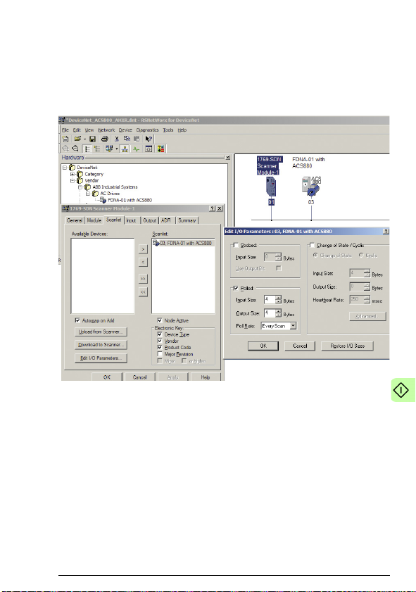
Start-up 73
4. Configure the DeviceNet Scanner. Add the drive to Scanlist
and edit I/O parameters. Select Polled or Change of
State/Cyclic. Then enter the input and output sizes of the I/O
assemblies that are used (for example, for Basic Speed
Control Assemblies 20 and 70, each size is set to 4 bytes.).
Page 74
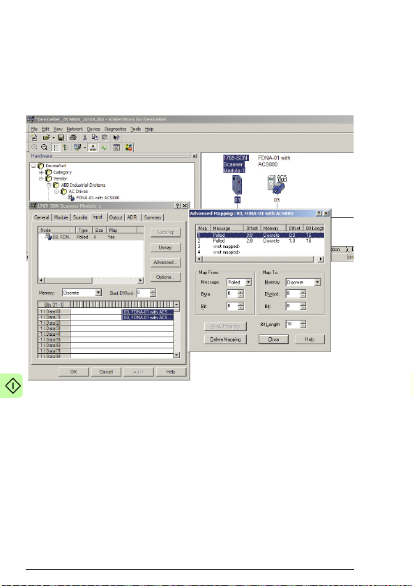
74 Start-up
5. For convenience, you can also edit the Input and Output
memory mappings. By default, the two 16-bit input words are
mapped into a single 32-bit double word. It is more convenient
to map them into separate double words. Output words can be
mapped similarly.
6. Download the scanner settings to the device in the online
mode.
Page 75

Start-up 75
7. Add your DeviceNet scanner to an RSLogix 5000 project. You
should get new Controller Tags Local:<slot>:I and
Local:<slot>:O. You can use them to access the data as
mapped above:
• Local:<slot>:O.Data[0] is the Control word
• Local:<slot>:O.Data[1] is the Reference
• Local:<slot>:I.Data[0] is the Status word
• Local:<slot>:I.Data[1] is the Actual value
Note: You may need to change the value of
Local:<slot>:O.CommandRegister.Run or
Local:<slot>:I.CommandRegister.Run to 1.
Page 76

76 Start-up
Page 77

Communication profiles 77
7
Communication profiles
What this chapter contains
This chapter describes the communication profiles used in the
communication between the DeviceNet network, the adapter
module and the drive.
Communication profiles
Communication profiles are ways of conveying control commands
(Control word, Status word, references and actual values) between
the master station and the drive.
With the FDNA-01 module, the DeviceNet network may employ
either the ODVA AC/DC drive profile or the ABB Drives profile.
Both are converted to the native profile (eg, DCU or FBA) by the
adapter module. In addition, two Transparent modes – for 16-bit
and 32-bit words respectively – are available. With the Transparent
modes, no data conversion takes place.
Page 78
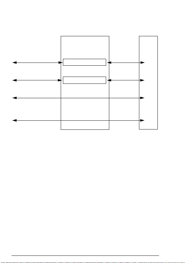
78 Communication profiles
FDNA-01 Drive
FDNA-01 profile
selection:
ABB Drives profile
Data conversion
ODVA AC/DC
Native profile
(eg, DCU,
FBA)
Data conversion
ODVA AC/DC
ABB Drives
Drive-specific profile
1)
(with 16-bit words)
Transparent32
Drive-specific profile
1)
(with 32-bit words)
DeviceNet
network
Transparent16
1)
Can be used if the native profile is supported by the drive.
Native profile
(eg, DCU,
FBA)
The figure below illustrates the operation of the profiles:
The following sections describe the Control word, the Status word,
references and actual values for the ODVA AC/DC drive and ABB
Drives communication profiles. Refer to the drive manuals for
details on the native profiles.
Page 79

Communication profiles 79
ODVA AC/DC drive profile
This section briefly describes the ODVA AC/DC drive profile.
Additional information can be obtained at www.odva.org
A DeviceNet node is modelled as a collection of abstract objects.
Each object represents the interface to and behavior of a
component within the product. The ODVA AC/DC drive profile
defines a collection of objects suitable for the control of the AC and
DC drives. The objects supported by the FDNA-01 DeviceNet
adapter are listed in Class objects on page 107.
The objects are defined by:
• Service
• Class
• Instance
• Attribute
• Behavior.
For example, to set the drive speed reference, the
Set_Attribute_Single service can be requested for the SpeedRef
attribute of the AC/DC drive object class. The resulting behavior is
that the reference speed of the drive is set to the requested value.
This is an example of explicit messaging, where each attribute of a
class is set individually. While this is allowed, it is inefficient.
Instead, implicit messaging using input and output assembly
instances is recommended. Implicit messaging allows the
DeviceNet Master to set or get predefined groups of attributes in a
single message exchange. The assembly instances supported by
the adapter module are listed and defined in Assembly objects on
page 74.
.
ODVA output attributes
This section briefly describes the instances found in the output
assemblies of the ODVA AC/DC drive profile. Note that all output
assembly instances do not support all attributes listed here.
Page 80

80 Communication profiles
Run Forward & Run Reverse (Control supervisor object)
These attributes are used to assert run and stop commands to the
Control supervisor object state machine according to the following
Run/Stop event matrix. See State (Control supervisor object) on
page 60.
RunFwd RunRev Trigger event Run type
00Stop N/A
0
→ 10 Run RunFwd
00
0
→ 10 → 1 No Action N/A
1 1 No Action N/A
0
→ 11 Run RunRev
11
Fault Reset (Control supervisor object)
This attribute resets a drive fault on a transition from zero to one if
the condition that caused the fault has been cleared.
Net Ctrl (Control supervisor object)
This attribute requests that the drive Run/Stop command is
supplied locally (Net Ctrl = 0) or by the network (Net Ctrl = 1).
Net Ref (AC/DC drive object)
This attribute requests that the drive Speed and Torque
References are supplied locally (Net Ref = 0) or by the network
(Net Ref = 1).
Speed Reference (AC/DC drive object)
This attribute is the speed reference for the drive. The units are
scaled by the Speed Scale attribute of the AC/DC drive object. See
Table 4. for details.
→ 1 Run RunRev
→ 0 Run RunFwd
Page 81

Communication profiles 81
Mf UsOsr
Dfr
×
×
=
Hz30
rpm1800
Hz60rpm1900
Mss
Mf UsOsr
Dfr =
×
×=×
×
=
UsOsr Dsr
×
=
Scalar mode
When the drive is operating in the scalar mode, the adapter
module provides the drive with a frequency reference. The ODVA
AC/DC drive profile uses rpm units for the Speed Reference. The
drive frequency reference is calculated as follows:
Mss
where
Dfr = Drive frequency reference in Hz
Osr = ODVA Speed Reference
Us = ODVA speed unit (see 10 ODVA SPEED SCALE on page 41)
Mf = Motor nominal frequency in Hz
Mss = Motor synchronous speed in rpm (not motor nominal speed)
For example, for a 4-pole 60 Hz motor (Mss = 1800 rpm) with a
unit of 1 rpm and an ODVA Speed Reference of 900, the drive
frequency reference is:
Vector mode
When the drive is operating in the vector mode, the adapter
module provides the drive with a speed reference. The ODVA
AC/DC drive profile uses rpm units for the speed reference. The
drive speed reference is calculated as follows:
where
Dsr = Drive Speed Reference in rpm
Osr = ODVA Speed Reference
Us = ODVA speed unit (see 10 ODVA SPEED SCALE on page 41)
Page 82

82 Communication profiles
450rpm 0.5rpm 900 UsOsr Dsr
=×=
×
UtOtr 100
Dtr
×
×
=
50
m
Nm1500100
UtOtr 100
Dtr =
×
×=×
×
=
For example, for an ODVA Speed Reference of 900 rpm with a unit
of 0.5 rpm, the drive speed reference is:
=
Torque Reference (AC/DC drive object)
This attribute is the torque reference for the drive. The units are
scaled by the Torque Scale attribute of the AC/DC drive object.
See Table 5. for details.
The adapter module provides the drive with a Torque Reference in
percent of the motor nominal torque. The ODVA AC/DC drive
profile uses Newton-meter (N·m) units for the Torque Reference.
The drive torque reference is calculated as follows:
Mt
where
Dtr = Drive torque reference in percent of motor nominal torque
Otr = ODVA Torque Reference
Ut = ODVA torque unit (see 11 ODVA TORQUE SCALE on page 42)
Mt = Motor nominal torque in Nm.
For example, for a 1000 Nm motor nominal torque with a unit of 1
Nm and an ODVA Torque Reference of 500, the drive torque
reference is:
N
Mt
1000
Page 83

Communication profiles 83
ODVA input attributes
This section briefly describes the instances found in the input
assemblies of the ODVA AC/DC drive profile. Note that all input
assembly instances do not support all attributes listed here.
Faulted (Control supervisor object)
This attribute indicates that the drive has experienced a fault. The
fault code may be read from the FaultCode attribute of the Control
supervisor object.
Warning (Control supervisor object)
This attribute indicates that the drive is experiencing a warning
condition. The warning code may be read from the WarnCode
attribute of the Control supervisor object.
Running Forward (Control supervisor object)
This attribute indicates that the drive is running in the forward
direction.
Running Reverse (Control supervisor object)
This attribute indicates that the drive is running in the reverse
direction.
Ready (Control supervisor object)
This attribute indicates that the Control supervisor object state
machine is in the Ready, Running or Stopping state. See State
(Control supervisor object) on page 60.
Ctrl From Net (Control supervisor object)
This attribute indicates if the Run/Stop command is being supplied
locally (Ctrl From Net = 0) or by the network (Ctrl From Net = 1).
Ref From Net (AC/DC drive object)
This attribute indicates if the Speed and Torque References are
being supplied locally (Ref From Net = 0) or by the network (Ref
From Net = 1).
Page 84

84 Communication profiles
At Reference (AC/DC drive object)
This attribute indicates that the drive is operating at the specified
Speed or Torque Reference.
State (Control supervisor object)
This attribute indicates the current state of the Control supervisor
object.
State Description State Description
0 Vendor Specific 4 Enabled
1 Startup 5 Stopping
2 Not Ready 6 Fault Stop
3 Ready 7 Faulted
Page 85

Non Existent
Star tup
Not Ready
Ready
Enabled
Faulted
Fault stop
Stopping
Power off
ALM=1
ALM=1
DEC=1
DEC=0
Power-on AND not RDY
ALM=1
FaultRst
FWD OR REV
ALM=1
DEC=0
Power on
Power on
Power-on
AND RDY
FWD OR REV
ALM = Alarm
DEC = Deceleration
FWD = Forward
REV = Reverse
RDY = Ready
Communication profiles 85
The ODVA state transition diagram is shown below:
Page 86

86 Communication profiles
f
Mss Dfa
Osa
×
×
=
900
1rpm60Hz
1800rpm30Hz
UsMf
MssDfa
Osa =
×
×
=
×
×
=
Speed Actual (AC/DC drive object)
This attribute indicates the actual speed at which the drive is
operating. The units are scaled by the SpeedScale attribute of the
AC/DC drive object. See Table 4. for details.
Scalar mode
When the drive is operating in the scalar mode, the drive provides
the adapter module with a frequency actual. The ODVA AC/DC
drive profile uses rpm units for the speed actual. The ODVA Speed
Actual is calculated as follows:
UsM
where
Osa = ODVA Speed Actual
Dfa = Drive frequency actual in Hz
Us = ODVA speed unit (see 10 ODVA SPEED SCALE on page 41)
Mf = Motor nominal frequency in Hz
Mss = Motor synchronous speed in rpm (not motor nominal speed)
For example, for a 4 pole 60 Hz motor (Mss = 1800 rpm) with a unit
of 1 rpm and a Drive frequency actual of 30 Hz, the ODVA Speed
Actual is:
Page 87

Communication profiles 87
Dsa
Osa =
900
rpm0.5
rpm450
Us
Dsa
Osa ===
MtDta
Ota
×
×
=
Vector Mode
When the drive is operating in the vector mode, the drive provides
the adapter module with a speed actual. The ODVA AC/DC drive
profile uses rpm units for the speed actual. The ODVA Speed
Actual is calculated as follows:
Us
where
Dsa = Drive speed actual in rpm
Osa = ODVA Speed Actual
Us = ODVA speed unit (see 10 ODVA SPEED SCALE on page 41)
For example, for a drive speed actual of 900 rpm with a unit of 0.5
rpm, the ODVA Speed Actual is:
Torque Actual (AC/DC drive object)
This attribute indicates the actual torque at which the drive is
operating. The units are scaled by the Torque Scale attribute of the
AC/DC drive object. See Table 5. for details.
The drive provides the adapter module with a torque actual in
percent of the motor nominal torque. The ODVA AC/DC drive
profile uses Newton-meter (N·m) units for the Torque Actual. The
ODVA Torque Actual is calculated as follows:
Ut100
where
Dta = Drive torque actual in percent of motor nominal torque
Ota = ODVA Torque Actual
Ut = ODVA torque unit
Mt = Motor nominal torque in Nm
(see 11 ODVA TORQUE SCALE on page 42)
Page 88

88 Communication profiles
500
Nm100050
t
MtDta
Ota =
×
×
=
×
×
=
For example, for a 1000 Nm motor nominal torque with a unit of 1
Nm and a drive torque actual of 50%, the ODVA Torque Actual is:
100
U
Nm1100
ABB Drives communication profile
Control word and Status word
The Control word is the principal means for controlling the drive
from a fieldbus system. It is sent by the fieldbus master station to
the drive through the adapter module. The drive switches between
its states according to the bit-coded instructions in the Control
word, and returns status information to the master in the Status
word.
The contents of the Control word and the Status word are detailed
below. The drive states are presented on page 93.
Control word contents
The table below shows the contents of the Control word for the
ABB Drives communication profile. The upper case boldface text
refers to the states shown in the state machine on page 93.
Bit Name Value STATE/Description
0 OFF1_
CONTROL
1 OFF2_
CONTROL
1 Proceed to READY TO OPERATE.
0 Stop along currently active deceleration
ramp. Proceed to OFF1 ACTIVE; proceed
to READY TO SWITCH ON unless other
interlocks (OFF2, OFF3) are active.
1 Continue operation (OFF2 inactive).
0 Emergency OFF, coast to stop.
Proceed to OFF2 ACTIVE; proceed to
SWITCH-ON INHIBITED.
Page 89

Communication profiles 89
Bit Name Value STATE/Description
2 OFF3_
CONTROL
3 INHIBIT_
OPERATION
4RAMP_OUT_
ZERO
5 RAMP_HOLD 1 Enable ramp function.
6RAMP_IN_
ZERO
1 Continue operation (OFF3 inactive).
0 Emergency stop, stop within time defined
with the drive parameter. Proceed to OFF3
ACTIVE; proceed to SWITCH-ON
INHIBITED.
Warni ng: Ensure motor and driven
machine can be stopped using this stop
mode.
1 Proceed to OPERATION ENABLED.
Note: Run enable signal must be active;
see drive documentation. If the drive is set
to receive the Run enable signal from the
fieldbus, this bit activates the signal.
0 Inhibit operation. Proceed to OPERATION
INHIBITED.
1 Normal operation. Proceed to RFG:
OUTPUT ENABLED.
0 Force the Ramp Function Generator output
to zero. Drive ramps to stop (current and
DC voltage limits in force).
Proceed to RFG: ACCELERATOR
ENABLED.
0 Halt ramping (Ramp Function Generator
output held).
1 Normal operation. Proceed to
OPERATION.
Note: This bit is effective only if the
fieldbus interface is set as the source for
this signal by drive parameters.
0 Force the Ramp Function Generator input
to zero.
Page 90

90 Communication profiles
Bit Name Value STATE/Description
7 RESET 0=>1 Fault reset if an active fault exists. Proceed
8…9 Reserved.
10 REMOTE_
CMD
11 EXT_CTRL_
LOC
12… 15Reserved.
to SWITCH-ON INHIBITED.
Note: This bit is effective only if the
fieldbus interface is set as the source for
this signal by drive parameters.
0 Continue normal operation.
1 Fieldbus control enabled.
0Control
1 Select External Control Location EXT2.
0 Select External Control Location EXT1.
word and reference not getting
through to the drive, except for CW bits
OFF1, OFF2 and OFF3.
Effective if the control location
parameterized to be selected from the
fieldbus.
Effective if the control location
parameterized to be selected from the
fieldbus.
Page 91

Communication profiles 91
Status word contents
The table below shows the contents of the Status word for the ABB
Drives communication profile. The upper case boldface text refers
to the states shown in the state machine on page 93.
Bit Name Value STATE/Description
0 RDY_ON 1 READY TO SWITCH ON.
0 NOT READY TO SWITCH ON.
1 RDY_RUN 1 READY TO OPERATE.
0 OFF1 ACTIVE.
2 RDY_REF 1 OPERATION ENABLED.
0 OPERATION INHIBITED.
3 TRIPPED 1 FAULT.
0 No fault.
4 OFF_2_STA 1 OFF2 inactive.
0 OFF2 ACTIVE.
5 OFF_3_STA 1 OFF3 inactive.
0 OFF3 ACTIVE.
6SWC_ON_
INHIB
7 ALARM 1 Warning/Alarm.
8AT_
SETPOINT
9 REMOTE 1 Drive control location: REMOTE (EXT1 or
1 SWITCH-ON INHIBITED.
0–
0 No warning/alarm.
1 OPERATION. Actual value equals
reference = is within tolerance limits, ie, in
speed control, speed error is 10% max. of
nominal motor speed.
0 Actual value differs from reference = is
outside tolerance limits.
EXT2).
0 Drive control location: LOCAL.
Page 92

92 Communication profiles
Bit Name Value STATE/Description
10 ABOVE_
LIMIT
11 EXT_CTRL_
LOC
12 EXT_RUN_
ENABLE
13…14Reserved.
1 Actual frequency or speed equals or
exceeds the supervision limit (set by the
drive parameter). Valid in both directions of
rotation.
0 Actual frequency or speed within
supervision limit.
1 External Control Location EXT2 selected.
Note concerning ACS880: This bit is
effective only if the fieldbus interface is set
as the target for this signal by drive
parameters. User bit 0 selection (06.30).
0 External Control Location EXT1 selected.
1 External Run Enable signal received.
Note concerning ACS880: This bit is
effective only if the fieldbus interface is set
as the target for this signal by drive
parameters. User bit 1 selection (06.31).
0 No External Run Enable signal received
15 FBA_ERROR 1 Communication error detected by the
fieldbus adapter module.
0 Fieldbus adapter communication OK.
Page 93

Communication profiles 93
MAINS OFF
Power ON (CW Bit0=0)
(SW Bit6=1)
(SW Bit0=0)
from any state
(CW=xxxx x
1
xx xxxx x
110
)
(SW Bit1=1)
n(f)=0 / I=0
(SW Bit2=0)
ABCD
(CW Bit3=0)
operation
inhibited
OFF1
(CW Bit0=0)
(SW Bit1=0)
(SW Bit0=1)
(CW Bit3=1
and
SW Bit12=1)
CD
(CW Bit5=0)
(SW Bit2=1)
(SW Bit5=0)
from any state from any state
Emergency Stop
OFF3
(CW Bit2=0)
n(f)=0 / I=0
Emergency OFF
OFF2
(CW Bit1=0)
(SW Bit4=0)
B
BCD
(CW Bit4=0)
(CW=xxxx x
1
xx xxx
1 1111
)
(CW=xxxx x
1
xx xx
11 1111
)
D
(CW Bit6=0)
A
C
(CW=xxxx x
1
xx x
111 1111
)
(SW Bit8=1)
D
from any state
Fault
(SW Bit3=1)
(CW Bit7=1)
(CW=xxxx x
1
xx xxxx x
111
)
(CW=xxxx x
1
xx xxxx
1111
and SW Bit12=1)
ABB Drives
Communication
Profile
SWITCH-ON
INHIBITED
NOT READY TO
SWITCH ON
READY TO
SWITCH ON
READY TO
OPERATE
OPERATION
INHIBITED
OFF1
ACTIVE
OPERATION
ENABLED
RFG: OUTPUT
ENABLED
RFG: ACCELERATOR
ENABLED
OPERATION
OFF2
ACTIVE
FAULT
OFF3
ACTIVE
state
condition
rising edge
the bitof
CW = Control word
SW = Status word
n = Speed
I = Input Current
RFG = Ramp Function
Generator
f= Frequency
State machine
The state machine for the ABB Drives communication profile is
shown below.
Page 94
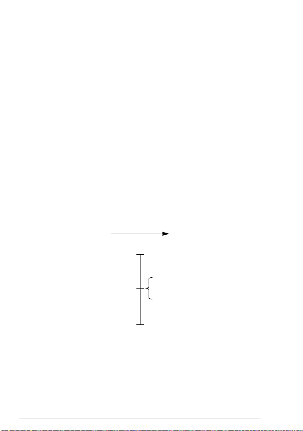
94 Communication profiles
DriveFieldbus
REFx MAX / Speed scale
-(REFx MAX) / Speed scale
0
REF2: -10000
REF1: -20000
REF2: 10000
REF1: 20000
REFx MIN
-(REFx MIN)
References
References are 16-bit signed two's complement integers. A
negative reference indicates a reverse direction of rotation.
ABB drives can receive control information from multiple sources
including analogue and digital inputs, the drive control panel and a
communication module (for example, FDNA-01). To have the drive
controlled through the fieldbus, the module must be defined as the
source for control information, for example, reference.
Scaling
References are scaled as shown below.
Note: The values of REF1 MAX and REF2 MAX are set with drive
parameters. See the drive documentation for further information.
In ACSM1, ACS850, ACQ810 and ACS880, the speed reference
(REFx) in decimal (0…20000) corresponds to 0 … 100% of the
speed scaling value (as defined with a drive parameter, eg,
ACS880 parameter 46.10 Speed scaling).
In ACS355, drive parameter REFx MIN may limit the actual
minimum reference.
Page 95
Communication profiles 95
0
REFx MAX
-(REFx MAX)
0
ACT2: -10000
ACT1: -20000
ACT2: 10000
ACT1: 20000
DriveFieldbus
Actual values
Actual values are 16-bit signed two's complement integers
containing information on the operation of the drive. A negative
reference indicates a reverse direction of rotation. The functions to
be monitored are selected with a drive parameter.
Scaling
Actual values are scaled as shown below.
Note: The values of REF1 MAX and REF2 MAX are set with drive
parameters. See the drive documentation for further information.
Page 96

96 Communication profiles
Page 97

Communication protocol 97
8
Communication protocol
What this chapter contains
This chapter describes the DeviceNet communication protocol for
the adapter module and the configuration of the scanner. For
detailed information on DeviceNet communication, refer to ODVA
DeviceNet Specifications Release 2.0.
DeviceNet
DeviceNet is a protocol based on the CAN technology. CAN
specifies the physical layer interface. DeviceNet specifies the
wiring and the data transfer through CAN.
The FDNA-01 module is a device acting as a Group 2 only Server
realizing the Predefined Master Slave Connection Set functionality.
The Off-line Connection Set functionality and Unconnected
Message Manager (UCMM) are not supported.
Object modeling and functional properties
One of the main features of DeviceNet is object modeling. A group
of objects can be described with a Functional Profile. The FDNA01 adapter module realizes the ODVA AC/DC drive Functional
Profile with additional features.
Page 98

98 Communication protocol
Assembly objects
I/O assembly instances may also be referred to as Block Transfer
of data. Intelligent devices realizing a Functional Profile, such as
FDNA-01, have several objects. Since it is not possible to transmit
more than one object data through a single connection, it is
practical and more efficient to group attributes from different
objects into a single I/O connection (for example, a polled
connection) using the assembly object. The assembly object acts
as a tool for grouping these attributes.
The assembly selections described above are, in fact, instances of
the assembly object class. The FDNA-01 adapter module uses
static assemblies (in other words, fixed groupings of different
object data only). The following tables describe the assembly
instances supported by the adapter module.
Basic speed control assembly
The Basic speed control assembly is defined by the ODVA AC/DC
drive profile. The format of the output assembly is:
Instance 20
Byte Bit 7 Bit 6 Bit 5 Bit 4 Bit 3 Bit 2 Bit 1 Bit 0
0 Fault
1
2 Speed Reference (Low Byte)
3 Speed Reference (High Byte)
Reset
The format of the input assembly is:
Instance 70
Byte Bit 7 Bit 6 Bit 5 Bit 4 Bit 3 Bit 2 Bit 1 Bit 0
0 Running1
1
2 Speed Actual (Low Byte)
3 Speed Actual (High Byte)
(Fwd)
Run Fwd
Faulted
Page 99

Communication protocol 99
Basic speed control plus drive parameters
assembly
The Basic speed control plus drive parameters assembly, defined
by ABB, adds configurable drive parameters to the Basic speed
control assembly of the ODVA AC/DC drive profile.
The format of the output assembly is:
Instance 120
Byte Bit 7 Bit 6 Bit 5 Bit 4 Bit 3 Bit 2 Bit 1 Bit 0
0 Fault
Reset
1
2 Speed Reference (Low Byte)
3 Speed Reference (High Byte)
4 DATA OUT 1 Value (Low Byte)
5 DATA OUT 1 Value (High Byte)
6 DATA OUT 2 Value (Low Byte)
7 DATA OUT 2 Value (High Byte)
8 DATA OUT 3 Value (Low Byte)
9 DATA OUT 3 Value (High Byte)
10 DATA OUT 4 Value (Low Byte)
11 DATA OUT 4 Value (High Byte)
12 DATA OUT 5 Value (Low Byte)
13 DATA OUT 5 Value (High Byte)
14 DATA OUT 6 Value (Low Byte)
15 DATA OUT 6 Value (High Byte)
16 DATA OUT 7 Value (Low Byte)
17 DATA OUT 7 Value (High Byte)
18 DATA OUT 8 Value (Low Byte)
19 DATA OUT 8 Value (High Byte)
20 DATA OUT 9 Value (Low Byte)
Run
Fwd
Page 100

100 Communication protocol
Instance 120
Byte Bit 7 Bit 6 Bit 5 Bit 4 Bit 3 Bit 2 Bit 1 Bit 0
21 DATA OUT 9 Value (High Byte)
22 DATA OUT 10 Value (Low Byte)
23 DATA OUT 10 Value (High Byte)
The format of the input assembly is:
Instance 170
Byte Bit 7 Bit 6 Bit 5 Bit 4 Bit 3 Bit 2 Bit 1 Bit 0
0 Running1
1
2 Speed Actual (Low Byte)
3 Speed Actual (High Byte)
4 DATA IN 1 Value (Low Byte)
5 DATA IN 1 Value (High Byte)
6 DATA IN 2 Value (Low Byte)
7 DATA IN 2 Value (High Byte)
8 DATA IN 3 Value (Low Byte)
9 DATA IN 3 Value (High Byte)
10 DATA IN 4 Value (Low Byte)
11 DATA IN 4 Value (High Byte)
12 DATA IN 5 Value (Low Byte)
13 DATA IN 5 Value (High Byte)
14 DATA IN 6 Value (Low Byte)
15 DATA IN 6 Value (High Byte)
16 DATA IN 7 Value (Low Byte)
17 DATA IN 7 Value (High Byte)
18 DATA IN 8 Value (Low Byte)
19 DATA IN 8 Value (High Byte)
(Fwd)
Faulted
 Loading...