

Page 1
Options for ABB drives, inverters and converters
User’s manual
FCAN-01 CANopen adapter module
Page 2

List of related manuals
See section Related manuals on page 16.
Page 3
User’s manual
FCAN-01 CANopen adapter module
Table of contents
1. Safety
4. Mechanical installation
5. Electrical installation
6. Start-up
3AFE68615500 Rev D
EN
EFFECTIVE: 2012-01-25
© 2012 ABB Oy
All Rights Reserved.
Page 4

Page 5

Table of contents 5
Table of contents
1. Safety
What this chapter contains . . . . . . . . . . . . . . . . . . . . . . . . . . . . . 11
Use of warnings . . . . . . . . . . . . . . . . . . . . . . . . . . . . . . . . . . . . . 12
Safety in installation . . . . . . . . . . . . . . . . . . . . . . . . . . . . . . . . . . 13
2. About the manual
What this chapter contains . . . . . . . . . . . . . . . . . . . . . . . . . . . . . 15
Applicability . . . . . . . . . . . . . . . . . . . . . . . . . . . . . . . . . . . . . . . . 15
Compatibility . . . . . . . . . . . . . . . . . . . . . . . . . . . . . . . . . . . . . . . 15
Target audience . . . . . . . . . . . . . . . . . . . . . . . . . . . . . . . . . . . . . 15
Purpose of the manual . . . . . . . . . . . . . . . . . . . . . . . . . . . . . . . . 16
Related manuals . . . . . . . . . . . . . . . . . . . . . . . . . . . . . . . . . . . . 16
Before you start . . . . . . . . . . . . . . . . . . . . . . . . . . . . . . . . . . . . . 17
Contents . . . . . . . . . . . . . . . . . . . . . . . . . . . . . . . . . . . . . . . . . . . 18
Terms and abbreviations used in this manual . . . . . . . . . . . . . . 19
Terms . . . . . . . . . . . . . . . . . . . . . . . . . . . . . . . . . . . . . . . . . 19
CANopen abbreviations . . . . . . . . . . . . . . . . . . . . . . . . . . . . 20
3. Overview of the CANopen protocol and the FCAN-01
adapter module
What this chapter contains . . . . . . . . . . . . . . . . . . . . . . . . . . . . . 23
CANopen protocol . . . . . . . . . . . . . . . . . . . . . . . . . . . . . . . . . . . 23
Topology of the CANopen link . . . . . . . . . . . . . . . . . . . . . . . . . . 24
FCAN-01 CANopen adapter module . . . . . . . . . . . . . . . . . . . . . 25
Layout of the adapter module . . . . . . . . . . . . . . . . . . . . . . . . . . 26
4. Mechanical installation
What this chapter contains . . . . . . . . . . . . . . . . . . . . . . . . . . . . . 27
Delivery check . . . . . . . . . . . . . . . . . . . . . . . . . . . . . . . . . . . . . . 27
Mounting the adapter module . . . . . . . . . . . . . . . . . . . . . . . . . . 28
5. Electrical installation
What this chapter contains . . . . . . . . . . . . . . . . . . . . . . . . . . . . . 29
Page 6

6 Table of contents
General cabling instructions . . . . . . . . . . . . . . . . . . . . . . . . . . . . 29
Connecting the module to the CANopen network . . . . . . . . . . . 30
Bus termination . . . . . . . . . . . . . . . . . . . . . . . . . . . . . . . . . . . . . 31
AC and DC parameters for the CANopen network . . . . . . . . . . . 32
Bus cable and termination resistors . . . . . . . . . . . . . . . . . . . 32
6. Start-up
What this chapter contains . . . . . . . . . . . . . . . . . . . . . . . . . . . . . 35
Drive configuration . . . . . . . . . . . . . . . . . . . . . . . . . . . . . . . . . . . 35
CANopen connection configuration . . . . . . . . . . . . . . . . . . . 36
Data transfer rates supported. . . . . . . . . . . . . . . . . . . . . 36
FCAN-01 configuration parameters – group A (group 1) 37
FCAN-01 configuration parameters – group B (group 2) 51
FCAN-01 configuration parameters – group C (group 3) 54
Additional information on the virtual address area
allocation . . . . . . . . . . . . . . . . . . . . . . . . . . . . . . . . . . . . 57
Control locations . . . . . . . . . . . . . . . . . . . . . . . . . . . . . . . . . 58
Starting up ACS355 drives . . . . . . . . . . . . . . . . . . . . . . . . . . . . . 58
Parameter setting examples – ACS355 . . . . . . . . . . . . . . . . 59
CiA 402 vl velocity mode with default PDO mapping . . . 59
Speed and torque control using ABB Drives
communication profile with parameter-configured PDO
mapping . . . . . . . . . . . . . . . . . . . . . . . . . . . . . . . . . . . . . 61
Starting up ACSM1 drives . . . . . . . . . . . . . . . . . . . . . . . . . . . . . 64
Parameter setting examples – ACSM1 . . . . . . . . . . . . . . . . 66
Using position control with the CiA 402 Profile Position
mode. . . . . . . . . . . . . . . . . . . . . . . . . . . . . . . . . . . . . . . . 66
Starting up ACS850 drives . . . . . . . . . . . . . . . . . . . . . . . . . . . . . 69
Parameter setting examples – ACS850 . . . . . . . . . . . . . . . . 70
CiA 402 Velocity mode with default PDO mapping . . . . 70
ABB Drives communication profile with parameter-
configured PDO mapping . . . . . . . . . . . . . . . . . . . . . . . . 72
Starting up ACS880 drives . . . . . . . . . . . . . . . . . . . . . . . . . . . . . 75
Parameter setting examples – ACS880 . . . . . . . . . . . . . . . . 76
CiA 402 Velocity mode with default PDO mapping . . . . 76
Configuring the master station . . . . . . . . . . . . . . . . . . . . . . . . . . 78
Page 7

Table of contents 7
EDS files . . . . . . . . . . . . . . . . . . . . . . . . . . . . . . . . . . . . . . . 78
Configuring an ABB AC500 PLC . . . . . . . . . . . . . . . . . . . . . 79
7. Communication profiles
What this chapter contains . . . . . . . . . . . . . . . . . . . . . . . . . . . . . 87
Communication profiles . . . . . . . . . . . . . . . . . . . . . . . . . . . . . . . 87
CANopen device profile CiA 402 . . . . . . . . . . . . . . . . . . . . . . . . 89
Device Control state machine . . . . . . . . . . . . . . . . . . . . . . . 89
Modes of operation . . . . . . . . . . . . . . . . . . . . . . . . . . . . . . . 90
Homing mode . . . . . . . . . . . . . . . . . . . . . . . . . . . . . . . . . . . 90
Profile position mode . . . . . . . . . . . . . . . . . . . . . . . . . . . . . . 91
Position demand value. . . . . . . . . . . . . . . . . . . . . . . . . . 91
Position actual value . . . . . . . . . . . . . . . . . . . . . . . . . . . 91
Interpolated position mode . . . . . . . . . . . . . . . . . . . . . . . . . 91
Profile velocity mode . . . . . . . . . . . . . . . . . . . . . . . . . . . . . . 91
Target velocity . . . . . . . . . . . . . . . . . . . . . . . . . . . . . . . . 92
Velocity actual value . . . . . . . . . . . . . . . . . . . . . . . . . . . 92
Profile torque mode . . . . . . . . . . . . . . . . . . . . . . . . . . . . . . . 92
Target torque . . . . . . . . . . . . . . . . . . . . . . . . . . . . . . . . . 92
Torque actual value . . . . . . . . . . . . . . . . . . . . . . . . . . . . 92
Velocity mode . . . . . . . . . . . . . . . . . . . . . . . . . . . . . . . . . . . 93
Target velocity of CiA 402 Velocity mode . . . . . . . . . . . 93
Control effort of CiA 402 Velocity mode . . . . . . . . . . . . . 93
Control word and Status word of the CiA 402 profile . . . . . . 93
State machine . . . . . . . . . . . . . . . . . . . . . . . . . . . . . . . . 99
ABB Drives communication profile . . . . . . . . . . . . . . . . . . . . . . 100
Control word and Status word . . . . . . . . . . . . . . . . . . . . . . 100
Control word contents . . . . . . . . . . . . . . . . . . . . . . . . . 100
Status word contents . . . . . . . . . . . . . . . . . . . . . . . . . . 103
State machine . . . . . . . . . . . . . . . . . . . . . . . . . . . . . . . 105
References . . . . . . . . . . . . . . . . . . . . . . . . . . . . . . . . . . . . 106
Scaling . . . . . . . . . . . . . . . . . . . . . . . . . . . . . . . . . . . . . 106
Actual values . . . . . . . . . . . . . . . . . . . . . . . . . . . . . . . . . . . 107
Scaling . . . . . . . . . . . . . . . . . . . . . . . . . . . . . . . . . . . . . 107
Page 8

8 Table of contents
8. Communication protocol
What this chapter contains . . . . . . . . . . . . . . . . . . . . . . . . . . . . 109
CAN data frame . . . . . . . . . . . . . . . . . . . . . . . . . . . . . . . . . . . . 109
FCAN-01 boot-up sequence and
Network Management (NMT) . . . . . . . . . . . . . . . . . . . . . . . 111
Process Data Objects (PDO) . . . . . . . . . . . . . . . . . . . . . . . . . . 113
Rx PDO1 . . . . . . . . . . . . . . . . . . . . . . . . . . . . . . . . . . . . . . . . . 114
Tx PDO1 . . . . . . . . . . . . . . . . . . . . . . . . . . . . . . . . . . . . . . . . . 115
Rx PDO6 . . . . . . . . . . . . . . . . . . . . . . . . . . . . . . . . . . . . . . . . . 116
Tx PDO6 . . . . . . . . . . . . . . . . . . . . . . . . . . . . . . . . . . . . . . . . . 117
Rx PDO21 . . . . . . . . . . . . . . . . . . . . . . . . . . . . . . . . . . . . . . . . 118
Tx PDO21 . . . . . . . . . . . . . . . . . . . . . . . . . . . . . . . . . . . . . . . . 119
Mapping format . . . . . . . . . . . . . . . . . . . . . . . . . . . . . . . . . . . . 120
PDO configuration via the CAN bus . . . . . . . . . . . . . . . . . . . . . 121
Service Data Objects (SDO) . . . . . . . . . . . . . . . . . . . . . . . . . . 124
SDO Download . . . . . . . . . . . . . . . . . . . . . . . . . . . . . . . . . 124
SDO Upload . . . . . . . . . . . . . . . . . . . . . . . . . . . . . . . . . . . . 125
Read Service (SDO Upload) . . . . . . . . . . . . . . . . . . . . . . . . . . 126
Initiate SDO Upload Protocol . . . . . . . . . . . . . . . . . . . . . . . 126
Write Service (SDO Download) . . . . . . . . . . . . . . . . . . . . . . . . 127
Initiate SDO Download Protocol . . . . . . . . . . . . . . . . . . . . 127
Abort SDO Transfer . . . . . . . . . . . . . . . . . . . . . . . . . . . . . . . . . 128
Abort SDO Transfer Protocol . . . . . . . . . . . . . . . . . . . . . . . 128
Abort code description . . . . . . . . . . . . . . . . . . . . . . . . . 129
CANopen Object Dictionary . . . . . . . . . . . . . . . . . . . . . . . . . . . 131
Object Dictionary Structure . . . . . . . . . . . . . . . . . . . . . . . . 131
Communication profile area (1000...1FFF) . . . . . . . . . . . . 132
Manufacturer-specific profile area (2000...5FFF) . . . . . . . . 142
Manufacturer-specific profile objects . . . . . . . . . . . . . . 142
Drive actual signals and parameters . . . . . . . . . . . . . . 143
Standardized device profile area (6000...9FFF) . . . . . . . . 145
9. Diagnostics
What this chapter contains . . . . . . . . . . . . . . . . . . . . . . . . . . . . 151
LED indications . . . . . . . . . . . . . . . . . . . . . . . . . . . . . . . . . . . . 151
Page 9

Table of contents 9
10. Technical data
What this chapter contains . . . . . . . . . . . . . . . . . . . . . . . . . . . . 153
FCAN-01 . . . . . . . . . . . . . . . . . . . . . . . . . . . . . . . . . . . . . . . . . 154
CANopen link . . . . . . . . . . . . . . . . . . . . . . . . . . . . . . . . . . . . . . 155
11. Appendix A – Dictionary structure and entries
What this chapter contains . . . . . . . . . . . . . . . . . . . . . . . . . . . . 157
Description of transmission type . . . . . . . . . . . . . . . . . . . . . . . 158
Description of PDO COB-ID entry . . . . . . . . . . . . . . . . . . . . . . 158
PDO mapping entry structure – example . . . . . . . . . . . . . . . . . 159
12. Appendix B – CANopen error codes
What this chapter contains . . . . . . . . . . . . . . . . . . . . . . . . . . . . 161
Error codes . . . . . . . . . . . . . . . . . . . . . . . . . . . . . . . . . . . . . . . 161
Further information
Product and service inquiries . . . . . . . . . . . . . . . . . . . . . . . . . . 171
Product training . . . . . . . . . . . . . . . . . . . . . . . . . . . . . . . . . . . . 171
Providing feedback on ABB Drives manuals . . . . . . . . . . . . . . 171
Document library on the Internet . . . . . . . . . . . . . . . . . . . . . . . 171
Page 10

10 Table of contents
Page 11

Safety 11
1
Safety
What this chapter contains
The chapter presents the warning symbols used in this manual and
the safety instructions which you must follow when installing an
optional module into a drive, converter or inverter. If ignored,
physical injury or death may follow, or damage may occur to the
equipment. Read this chapter before you start the installation.
Page 12
12 Safety
Use of warnings
Warnings caution you about conditions which can result in serious
injury or death and/or damage to the equipment and advise on how
to avoid the danger. The following warning symbols are used in
this manual:
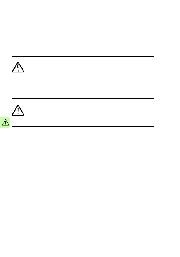
Electricity warning warns of hazards from electricity
which can cause physical injury and/or damage to the
equipment.
General warning warns about conditions, other than
those caused by electricity, which can result in physical
injury and/or damage to the equipment.
Page 13

Safety 13
Safety in installation
These warnings are intended for all who install an optional module
into a drive, converter or inverter.
WARNING! Ignoring the following instructions can cause
physical injury or death, or damage to the equipment.
• Only qualified electricians are allowed to install and maintain
the drive, converter or inverter!
• Disconnect the drive, converter or inverter into which the
optional module will be installed from all possible power
sources. After disconnecting, always wait for 5 minutes to let
the intermediate circuit capacitors discharge before you
proceed.
• Always ensure by measuring with a multimeter (impedance at
least 1 Mohm) that:
• there is no voltage between the input power terminals of
the drive, converter or inverter and the ground
• there is no voltage between the output power terminals of
the drive, converter or inverter and the ground.
• Do not work on the control cables when power is applied to the
external control circuits of the drive, converter or inverter.
Externally supplied control circuits may carry dangerous
voltage.
Page 14

14 Safety
Page 15

About the manual 15
2
About the manual
What this chapter contains
This chapter introduces this manual.
Applicability
This manual applies to the FCAN-01 CANopen adapter module
(+K457), SW version 1.046 or later.
Compatibility
The FCAN-01 CANopen adapter module is compatible with the
following drives:
• ACS355
• ACSM1
• ACS850
• ACS880.
Target audience
The reader is expected to have basic knowledge of fieldbus
interface, electrical fundamentals, electrical wiring practices and
how to operate the drive.
Page 16

16 About the manual
Purpose of the manual
The manual provides information on installing, commissioning and
using an FCAN-01 CANopen adapter module.
Related manuals
The related manuals are listed below.
Code (English)
Drive user’s manuals
ACS355 drives (0.37…22 kW,
0.5…30 hp) user’s manual
Drive hardware manuals and
guides
ACSM1-204 regen supply modules
(5.3 to 61 kW) hardware manual
ACSM1-04 drive modules (0.75 to
45 kW) hardware manual
ACSM1-04 drive modules (55 to
110 kW) hardware manual
ACSM1-04Lx liquid-cooled drive
modules (55 to 160 kW) hardware
manual
ACS850-04 (0.37…45 kW)
hardware manual
ACS850-04 (55…160 kW, 75…200
hp) hardware manual
ACS850-04 (200…500 kW,
250…600 hp) hardware manual
ACS880-01 (0.55 to 250 kW, 0.75
to 350 hp) hardware manual
3AUA0000066143
3AUA0000053713
3AFE68797543
3AFE68912130
3AUA0000022083
3AUA0000045496
3AUA0000045487
3AUA0000026234
3AUA0000078093
Page 17

About the manual 17
Code (English)
Drive firmware manuals and
guides
ACSM1 motion control program
firmware manual
ACSM1 speed and torque control
program firmware manual
ACSM1 regen supply control
program firmware manual
ACS850 standard control program
firmware manual
ACS880 primary control program
firmware manual
Option manuals and guides
FCAN-01 CANopen adapter
module user’s manual
3AFE68848270
3AFE68848261
3AUA0000052174
3AUA0000045497
3AUA0000085967
3AFE68615500
You can find manuals and other product documents in PDF format
on the Internet. See section Document library on the Internet on
the inside of the back cover. For manuals not available in the
Document library, contact your local ABB representative.
Before you start
It is assumed that the drive is installed and ready to operate before
you start the installation of the adapter module.
In addition to conventional installation tools, have the drive
manuals available during the installation as they contain important
information not included in this manual. The drive manuals are
referred to at various points of this manual.
Page 18

18 About the manual
Contents
The manual consists of the following chapters:
• Safety presents the safety instructions which you must follow
when installing a fieldbus adapter module.
• About the manual introduces this manual.
• Overview of the CANopen protocol and the FCAN-01 adapter
module contains a short description of the CANopen protocol
and the adapter module.
• Mechanical installation contains a delivery checklist and
instructions on mounting the adapter module.
• Electrical installation contains wiring and bus termination
instructions.
• Start-up presents the steps to take during the start-up of the
drive with the adapter module and gives examples of
configuring the master system.
• Communication profiles describes the communication profiles
used in communication between the CANopen network, the
adapter module and the drive.
• Communication protocol describes the communication on a
CANopen network.
• Diagnostics explains how to trace faults with the status LEDs
on the adapter module.
• Technical data contains the technical data of the adapter
module and the CANopen link.
• Appendix A – Dictionary structure and entries contains
information about PDO transmission and mapping.
• Appendix B – CANopen error codes contains reference tables
for decoding CANopen error messages.
Page 19

About the manual 19
Terms and abbreviations used in this manual
Terms
Term Explanation
Communication module Communication module is a name for a device
Command word See Control word.
Control word 16-bit or 32-bit word from master to slave with
FCAN-01 CANopen
adapter module
Object dictionary Local storage of all Communication Objects
Parameter Operating instruction for the drive. Parameters
Profile Adaptation of the protocol for certain application
Status word 16-bit or 32-bit word from slave to master with
(eg, a fieldbus adapter) through which the drive
is connected to an external communication
network (eg, a fieldbus). The communication
with the module is activated with a drive
parameter.
bit-coded control signals (sometimes called the
Command word)
One of the optional fieldbus adapter modules
available for ABB drives. FCAN-01 is a device
through which an ABB drive is connected to a
CANopen network.
(COB) recognized by a device
can be read and programmed with the drive
control panel, drive PC tools or through the
adapter module.
field, for example, drives. In this manual, driveinternal profiles (eg, DCU or FBA) are called
native profiles.
bit-coded status messages
Page 20

20 About the manual
CANopen abbreviations
Abbreviation Explanation
CAN Controller Area Network
CiA CAN in Automation, International User’s and
CMS CAN Message Specification; one of the service
COB Grouping of pre-defined data objects accessible
DBT Distributor; one of the service elements of the
EDS Electronic Data Sheet; a node-specific ASCII-
LMT Layer Management; one of the service
LSB Least significant bit/byte
MSB Most significant bit/byte
NMT Network Management; one of the service
OSI Open Systems Interconnection
PDO Process Data Object; a type of COB. Used for
Manufacturer’s Group
elements of the CAN Application Layer in the
CAN Reference Model
via the network.
CAN Application Layer in the CAN Reference
Model. It is the responsibility of the Distributor to
distribute COB IDs to the COBs that are used
by a CMS.
format file required when configuring the CAN
network. The EDS file contains general
information on the node and its dictionary
objects (parameters). EDS files for ABB Drives
are available at the Document library
(www.abb.com/drives
elements of the CAN Application Layer in the
CAN Reference Model. It serves to configure
parameters for each layer in the CAN
Reference Model.
elements of the CAN Application Layer in the
CAN Reference Model. It performs initialization,
configuration and error handling on a CAN
network.
transmitting time critical data, such as control
commands, references and actual values.
).
Page 21

About the manual 21
Abbreviation Explanation
RO Denotes read-only access.
RW Denotes read/write access.
SDO Service Data Object; a type of COB. Used for
transmitting non-time-critical data, such as
parameters.
Page 22

22 About the manual
Page 23

Overview of the CANopen protocol and the FCAN-01 adapter module 23
3
Overview of the CANopen protocol and the FCAN-01 adapter module
What this chapter contains
This chapter contains a short description of the CANopen protocol
and the FCAN-01 CANopen adapter module.
CANopen protocol
CANopen is a higher layer protocol based on the CAN (Control
Area Network) serial bus system and the CAL (CAN Application
Layer). CANopen assumes that the hardware of the connected
device has a CAN transceiver and a CAN controller as specified in
ISO 11898.
The CANopen Communication Profile, CiA 301, includes both
cyclic and event driven communication, which makes it possible to
reduce the bus load to minimum while still maintaining extremely
short reaction times. High communication performance can be
achieved at relatively low baud rates, thus reducing EMC problems
and cable costs.
CANopen device profiles define both direct access to drive
parameter and time critical process data communication. The
adapter module fulfills CiA (CAN in Automation) specification CiA
402 (CANopen device profile for drives and motion control).
Page 24
24 Overview of the CANopen protocol and the FCAN-01 adapter module
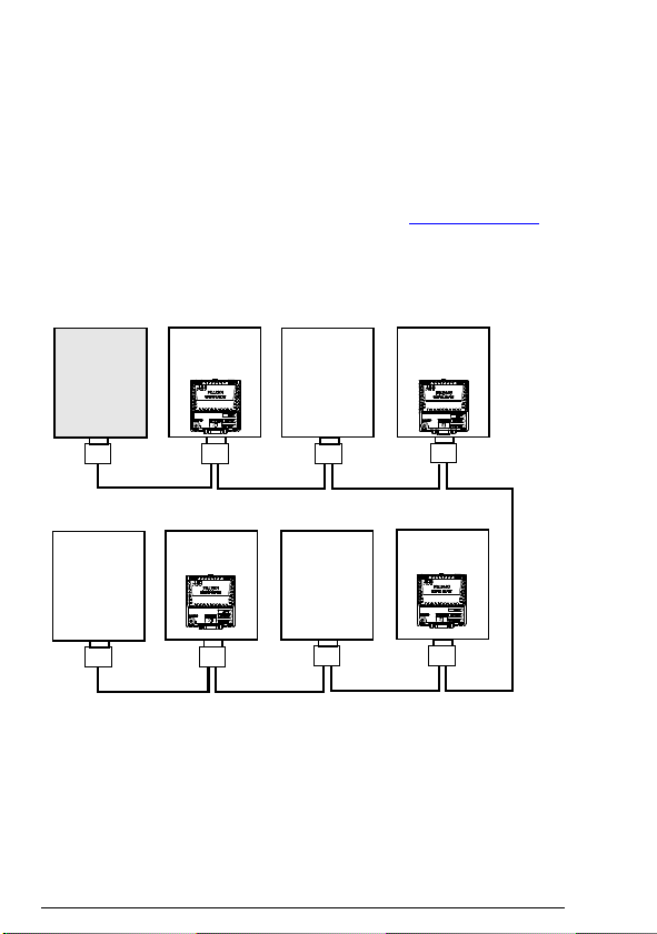
CANopen
master
ABB drive
Other slave
device
T = Termination
T
ABB drive
ABB drive
Other slave
device
Other slave
device
T
ABB drive
The physical medium of CANopen is a differentially driven two wire
bus line with common return according to ISO 11898. The
maximum length of the bus is limited by the communication speed.
The maximum theoretical number of nodes is 127. However, in
practice, the maximum number depends on the capabilities of the
used CAN transceivers.
Further information is available from the CAN in Automation
International Users and Manufacturers Group (www.can-cia.org
).
Topology of the CANopen link
The following figure describes the topology of the CANopen link.
Page 25

Overview of the CANopen protocol and the FCAN-01 adapter module 25
FCAN-01 CANopen adapter module
The FCAN-01 CANopen adapter module is an optional device for
ABB drives. It enables the connection of the drive to a CANopen
network. The drive is considered as a slave (server) on the
CANopen network.
Through the adapter module you can:
• give control commands to the drive
(for example, Start, Stop, Run enable)
• feed a motor speed, torque or position reference to the drive
• give a process actual value or a process reference to the PID
controller of the drive
• read status information and actual values from the drive
• change drive parameter values
• reset a drive fault.
The CANopen commands and services supported by the adapter
module are discussed in chapter Communication protocol. Refer to
the drive manuals as to which commands are supported by the
drive.
The adapter module is mounted into an option slot on the motor
control board of the drive. See the drive manuals for module
placement options.
Page 26
26 Overview of the CANopen protocol and the FCAN-01 adapter module
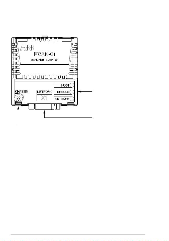
Diagnostic LEDs
(see chapter Diagnostics)
Bus connector X1
(see chapter Electrical
installation)
Mounting screw
Layout of the adapter module
The following figure describes the layout of the adapter module.
Page 27

Mechanical installation 27
4
Mechanical installation
What this chapter contains
This chapter contains a delivery checklist and instructions on
mounting the adapter module.
WARNING! Follow the safety instructions given in this
manual and the drive documentation.
Delivery check
The option package for the adapter module contains:
• CANopen adapter module, type FCAN-01
• this manual.
Page 28

28 Mechanical installation
Mounting the adapter module
The adapter module is inserted into its specific position in the drive.
The module is held in place with plastic pins and one screw. The
screw also provides the electrical connection between the module
and drive frame for cable shield termination.
When the module is installed, the signal and power connection to
the drive is made through a 20-pin connector. (All drives do not use
all the available signals so the connector on the drive may have
fewer pins.)
Mounting procedure:
1. Insert the module carefully into its position on the drive.
2. Fasten the screw.
Note: It is essential to install the screw properly to fulfill the EMC
requirements and to ensure the proper operation of the module.
For more information on mounting the adapter module, see the
drive manuals.
Page 29

Electrical installation 29
5
Electrical installation
What this chapter contains
This chapter contains:
• general cabling instructions
• bus termination instructions
• instructions on connecting the adapter module to the CANopen
network.
WARNING! Before installation, switch off the drive power
supply. Wait five minutes to ensure that the capacitor bank
of the drive is discharged. Switch off all dangerous
voltages connected from external control circuits to the inputs and
outputs of the drive.
General cabling instructions
• Arrange the bus cables as far away from the motor cables as
possible.
• Avoid parallel runs.
• Use bushings at cable entries.
Page 30
30 Electrical installation
5
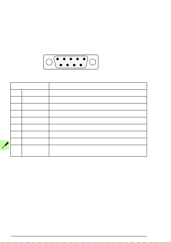
96
1
X1
SUB-D9
(male)
Connecting the module to the CANopen network
Connect the bus cable to connector X1 on the adapter module.
The connector pin allocation described below follows the CANopen
specification CiA 301.
X1 Description
1- Not in use
2 CAN_L CAN_L bus line (dominant low)
3 CAN_GND CAN ground
4- Not in use
5 CAN_SHLD Optional CAN shield
6 GND Optional ground
7 CAN_H CAN_H bus line (dominant high)
8- Not in use
9 CAN_V+ Optional CAN external power supply. Not supported
by FCAN-01.
Page 31

Electrical installation 31
CANopen
node
ON
CANopen
node
OFF
CANopen
node
ON
CANopen
node
OFF
Ter m . Ter m . Ter m. Te r m.
121 ohm
CAN_H
CAN_L
121 ohm
1%
Metal Film
1/4 W
1%
Metal Film
1/4 W
CANopen
node
CANopen
node
CANopen
node
…
Bus termination
Bus termination is required to prevent signal reflections from the
bus cable ends. The adapter module is not equipped with internal
bus termination. Therefore the first and last nodes of the bus must
be included with bus termination. Termination is done by
connecting one resistor between the CAN_H and CAN_L signals.
The nominal value for the terminating resistor is 120 ohms. The
resistors can be connected between the CAN_H and CAN_L wires
or a D-SUB connector with a built-on termination can be used.
In the following diagram, the built-on terminations of the D-SUB
connectors at the first and last nodes are switched on.
In the following diagram, the bus line is terminated with 121 ohm,
1 % (E96) resistors connected between the CAN_L and CAN_H
wires at each end.
Note: Further information on CANopen wiring is available from
www.can-cia.org
.
Page 32

32 Electrical installation
AC and DC parameters for the CANopen network
Bus cable and termination resistors
The cables, connectors, and termination resistors used in
CANopen networks must meet the requirements specified in ISO
11898.
The table below lists the standard values for DC parameters for
CANopen networks with less than 64 nodes:
Bus length
[m]
0…40 70 0.25…0.34 124 1000 at 40 m
40…300 < 60 0.34…0.6 150…300 > 500 at 100 m
300…600 < 40 0.5…0.6 150…300 > 100 at 500 m
600…1000 < 26 0.75…0.8 150…300 > 50 at 1 km
1)
Recommended cable for AC parameters: 120 ohm impedance and 5
ns/m line delay
Bus cable
Length-
related
resistance
[mohm/m]
1)
Cross-
section
2
[mm
]
Termination
resistance
[ohm]
Baud rate
[kbit/s]
With drop cables the recommended cable cross-section is
0.25…0.34 mm
In addition to the cable resistance, the real resistance of the
connectors should be taken into account in voltage drop
calculation. The transmission resistance of one connector should
2
.
be 2.5...10 mohm.
The following table lists the maximum bus cable length for different
node numbers (n), when
• minimum dominant value V
diff.out.min
• minimum differential input resistance R
• requested differential input voltage V
• minimum termination resistance R
= 1.5 V
diff.min
th.max
= 118 ohm.
T. mi n
= 20 kohm
= 1.0 V
Page 33

Electrical installation 33
Wire
cross-
section
2
[mm
Maximum length [m]
n = 32 n = 64 n = 100 n = 32 n = 64 n = 100
]
1)
Maximum length [m]
0.25 200 170 150 230 200 170
0.5 360 310 270 420 360 320
0.75 550 470 410 640 550 480
1)
Safety margin of 0.2
2)
Safety margin of 0.1
2)
Page 34

34 Electrical installation
Page 35

Start-up 35
6
Start-up
What this chapter contains
This chapter contains:
• information on configuring the drive for operation with the
adapter module
• drive-specific instructions on starting up the drive with the
adapter module
• examples of configuring the master station for communication
with the adapter module.
WARNING! Follow the safety instructions given in this
manual and the drive documentation.
Drive configuration
The following information applies to all drive types compatible with
the adapter module, unless otherwise stated.
Page 36

36 Start-up
CANopen connection configuration
After the adapter module has been mechanically and electrically
installed according to the instructions in chapters Mechanical
installation and Electrical installation, the drive must be prepared
for communication with the module.
The detailed procedure of activating the module for CANopen
communication with the drive depends on the drive type. Normally,
a parameter must be adjusted to activate the communication. See
the drive-specific start-up sections on pages 58, 64, 69 and 75.
Once communication between the drive and the adapter module
has been established, several configuration parameters are copied
to the drive. These parameters are shown in the tables below and
must be checked first and adjusted where necessary.
Note: Not all drives display descriptive names for the configuration
parameters. To help you identify the parameters in different drives,
the names displayed by each drive are given in grey boxes in the
tables.
An example on how to configure PDOs via the CAN bus is given in
section PDO configuration via the CAN bus.
Note: The new settings take effect only when the adapter module
is powered up the next time or when the fieldbus adapter refresh
parameter is activated.
Data transfer rates supported
The FCAN-01 CANopen adapter module supports the following
CANopen communication speeds: 50 kbit/s, 100 kbit/s, 125 kbit/s,
250 kbit/s, 500 kbit/s, 1 Mbit/s.
Note: 100 kbit/s is not recommended for a new installation.
Page 37

Start-up 37
FCAN-01 configuration parameters – group A (group 1)
Note: The actual parameter group number depends on the drive
type. Group A (group 1) corresponds to:
• parameter group 51 in ACS355, ACSM1 and ACS850
• parameter group 51 in ACS880 if the adapter is installed as
fieldbus adapter A or group 54 if the adapter is installed as
fieldbus adapter B.
No. Name/Value Description Default
01 FBA TYPE Read-only. Shows the fieldbus adapter type as
02 NODE ID Selects the node address of the module.
ACS355:
FB PAR 2
ACSM1:
FBA PAR2
ACS850:
FBA par2
ACS880:
Node ID
1…127 Node address
detected by the drive. Value cannot be adjusted
by the user.
If the value is 0 = None, the communication
between the drive and the module has not been
established.
Each device on the CANopen network must
have a unique node identifier. Used to define a
node identifier for the drive it is connected to.
setting
1 =
CANopen
3
Page 38

38 Start-up
No. Name/Value Description Default
03 BIT RATE Sets the bit rate for the CANopen interface.
ACS355:
FB PAR 3
ACSM1:
FBA PAR3
ACS850:
FBA par3
ACS880:
Bit rate
0 = 1 Mbit/s 1 Mbit/s
1 = 500 kbit/s 500 kbit/s
2 = 250 kbit/s 250 kbit/s
3 = 125 kbit/s 125 kbit/s
4 = 100 kbit/s 100 kbit/s
5 =50kbit/s 50kbit/s
04 CONF LOC Selects the source of the PDO configuration.
ACS355:
FB PAR 4
ACSM1:
FBA PAR4
ACS850:
FBA par4
ACS880:
Conf location
0 = Network PDO configuration via CAN bus: CANopen
1 = Parameters PDO configuration with drive parameters:
This is user selectable, but must be the same
on every node on the CANopen network.
Note: 100 kbit/s is not recommended for a new
installation.
Note: The first mapping entries of the Tx/Rx
PDO1 and Tx/Rx PDO6 are fixed in the
ACS355 drive.
Note: Make sure that the PLC does not
overwrite the selected configuration during the
initialization phase when the configuration is
taken from the FCAN-01 configuration
parameter groups.
objects 1400h, 1600h, 1405h, 1605h, 1414h,
1614h, 1800h, 1A00h, 1805h, 1A05h, 1814h
and 1A14h only.
adapter module configuration parameter group
A (group 1), group B (group 2) and group C
(group 3) (initial values).
setting
3 =125
kbit/s
0
Page 39

Start-up 39
No. Name/Value Description Default
05 PROFILE Selects the used communication profile used by
ACS355:
FB PAR 5
ACSM1:
FBA PAR5
ACS850:
FBA par5
ACS880:
Profile
0 = CiA 402 CANopen device profile CiA 402 selected
1 = ABB Drives ABB Drives profile selected
2 = Transp. 16 Transparent 16 profile selected
3 = Transp. 32 Transparent 32 profile selected
06 T16 SCALE Defines the reference multiplier/actual value
ACS355:
FB PAR 6
ACSM1:
FBA PAR6
ACS850:
FBA par6
ACS880:
T16 scale
0…65535 Reference multiplier/actual value divisor
the adapter module:
For more information on the communication
profiles, see chapter Communication profiles.
divisor for the adapter module. The parameter
is effective only when the Transparent 16 profile
is selected AND the drive is using the native
communication profile (for example, DCU or
FBA) and a 16-bit transparent Reference
1/Actual value 1.
With an ACS355 drive, the speed reference
from the PLC is multiplied by the value of this
parameter plus one. For example, if the
parameter has a value of 99 and a reference of
1000 given by the master, the reference will be
multiplied by 99 + 1 = 100 an d forwarded to the
drive as 100000. According to the DCU profile,
this value is interpreted as a reference of 100
rpm in the drive.
With ACSM1, ACS850 and ACS880, setting
this parameter to 65535 provides the
approximation of 1 ≈ 1 rpm.
setting
1 = ABB
Drives
99
Page 40

40 Start-up
No. Name/Value Description Default
07 RPDO1-COB-ID Defines the COB-ID for Rx PDO1.
ACS355:
FB PAR 7
ACSM1:
FBA PAR7
ACS850:
FBA par7
ACS880:
RPDO1-COB-ID
0 = Disable Rx PDO1 is not valid (disabled). COB-ID is
1 = Default Rx PDO1 is valid and configured to use the
385…1407 (dec) =
181h … 57Fh
08 RPDO1-TR TYPE Defines the Rx PDO1 transmission type. See
ACS355:
FB PAR 8
ACSM1:
FBA PAR8
ACS850:
FBA par8
ACS880:
RPDO1-TR type
0…255 (dec) Rx PDO1 transmission type. See section
Note: It is recommended to use the default
COB-ID.
80000200h + Node-ID.
default COB-ID (200h + Node-ID).
Rx PDO1 is valid and configured to use a
custom COB-ID defined with this parameter.
COB-ID must be within the allowed PDO COBID range (181h - 57Fh).
chapter Appendix A – Dictionary structure and
entries.
Description of transmission type on page 158.
setting
1
255
Page 41

Start-up 41
No. Name/Value Description Default
09 RPDO1-EV TIME Defines the event time (time-out time) for the
ACS355:
FB PAR 9
ACSM1:
FBA PAR9
ACS850:
FBA par9
ACS880:
RPDO1-EV time
0 = Disable Time-out supervision is disabled.
1…65535 (ms) Event time in ms
10 TPDO1-COB-ID Defines the COB-ID for Rx PDO6.
ACS355:
FB PAR 10
ACSM1:
FBA PAR10
ACS850:
FBA par10
ACS880:
TPDO1-COB-ID
0 = Disable Tx PDO1 is not valid (disabled). COB-ID is
1 = Default Tx PDO1 is valid and configur ed to use the
385…1407 (dec) =
181h … 57Fh
Rx PDO1 in the asynchronous transmission
mode. If the Rx PDO1 communication between
the adapter module and the bus master fails,
the adapter module sets the communication
between the module and the drive to the off-line
mode.
Event timer (time-out timer) elapses as a
multiple of 1 ms of the entry of this parameter.
Note: The time-out supervision is activated
upon a successful reception of an Rx PDO1.
Note: It is recommended to use the default
COB-ID.
80000180h + Node-ID.
default COB-ID (180h + Node-ID).
Tx PDO1 is valid and configured to use a
custom COB-ID defined with this parameter.
COB-ID must be within the allowed PDO COBID range (181h - 57Fh).
setting
0 =
Disable
1 =
Default
Page 42

42 Start-up
No. Name/Value Description Default
11 TPDO1-TR TYPE Defines the PDO1 transmission type. See
ACS355:
FB PAR 11
ACSM1:
FBA PAR11
ACS850:
FBA par11
ACS880:
TPDO1-TR type
0…255 (dec) PDO1 transmission type. See section
12 TPDO1-EV TIME Defines the event time for the Tx PDO1
ACS355:
FB PAR 12
ACSM1:
FBA PAR12
ACS850:
FBA par12
ACS880:
TPDO1-EV time
0 = Disable Event timer is disabled.
1…65535 (ms) Event time in ms.
13 RPDO6-COB-ID Defines the COB-ID for Rx PDO6.
ACS355:
FB PAR 13
ACSM1:
FBA PAR13
ACS850:
FBA par13
ACS880:
RPDO6-COB-ID
0 = Disable Rx PDO6 is not valid (disabled). COB-ID is
1 = Default Rx PDO6 is valid and configured to use the
385…1407 (dec) =
181h … 57Fh
chapter Appendix A – Dictionary structure and
entries.
Description of transmission type on page 158.
asynchronous transmission mode.
Event timer elapses as a multiple of 1 ms of the
entry of this parameter.
Note: It is recommended to use the default
COB-ID.
80000300h + Node-ID.
default COB-ID (300h + Node-ID).
Rx PDO1 is valid and configured to use a
custom COB-ID defined with this parameter.
COB-ID must be within the allowed PDO COBID range (181h - 57Fh).
setting
255
0 =
Disable
0 =
Disable
Page 43

Start-up 43
No. Name/Value Description Default
14 RPDO6-TR TYPE Defines the Rx PDO6 transmission type. See
ACS355:
FB PAR 14
ACSM1:
FBA PAR14
ACS850:
FBA par14
ACS880:
RPDO6-TR type
0…255 (dec) Rx PDO6 transmission type. See section
15 RPDO6-EV TIME Defines the event time (time-out time) for the
ACS355:
FB PAR 15
ACSM1:
FBA PAR15
ACS850:
FBA par15
ACS880:
RPDO6-EV time
0 = Disable Time-out supervision is disabled.
1…65535 (ms) Event time in ms.
16 TPDO6-COB-ID Defines the COB-ID for Tx PDO6.
ACS355:
FB PAR 16
ACSM1:
FBA PAR16
ACS850:
FBA par16
ACS880:
TPDO6-COB-ID
0 = Disable Tx PDO6 is not valid (disabled). COB-ID is
1 = Default Tx PDO6 is valid and configur ed to use the
385…1407 (dec) =
181h … 57Fh
chapter Appendix A – Dictionary structure and
entries.
Description of transmission type on page 158.
Rx PDO6 in the asynchronous transmission
mode. If the Rx PDO6 communication between
the adapter module and the bus master fails,
the adapter module sets the communication
between the module and the drive to the off-line
mode.
Event timer (time-out timer) elapses as a
multiple of 1 ms of the entry of this parameter.
Note: The time-out supervision is activated
upon a successful reception of an Rx PDO6.
Note: It is recommended to use the default
COB-ID.
80000280h + Node-ID.
default COB-ID (280h + Node-ID).
Tx PDO6 is valid and configured to use a
custom COB-ID defined with this parameter.
COB-ID must be within the allowed PDO COBID range (181h - 57Fh).
setting
255
0 =
Disable
0 =
Disable
Page 44

44 Start-up
No. Name/Value Description Default
17 TPDO6-TR TYPE Defines the Tx PDO6 transmission type. See
ACS355:
FB PAR 17
ACSM1:
FBA PAR17
ACS850:
FBA par17
ACS880:
TPDO6-TR type
0…255 (dec) Tx PDO6 transmission type. See section
18 TPDO6-EV TIME Defines the event time for the Tx PDO6
ACS355:
FB PAR 18
ACSM1:
FBA PAR18
ACS850:
FBA par18
ACS880:
TPDO6-EV time
0 = Disable Event timer is disabled.
1…65535 (ms) Event time in ms.
19 RPDO21-COB-ID Defines the COB-ID for Rx PDO21.
ACS355:
FB PAR 19
ACSM1:
FBA PAR19
ACS850:
FBA par19
ACS880:
RPDO21-COB-ID
0 = Disable Rx PDO21 is not valid (disabled). COB-ID is
1 = Default Rx PDO21 is valid and configured to use the
385…1407 (dec) =
181h … 57Fh
chapter Appendix A – Dictionary structure and
entries.
Description of transmission type on page 158.
asynchronous transmission mode.
Event timer elapses as a multiple of 1 ms of the
entry of this parameter.
Note: It is recommended to use the default
COB-ID.
80000400h + Node-ID.
default COB-ID (400h + Node-ID).
Rx PDO21 is valid and configured to use a
custom COB-ID defined with this parameter.
COB-ID must be within the allowed PDO COBID range (181h - 57Fh).
setting
255
0 =
Disable
0 =
Disable
Page 45

Start-up 45
No. Name/Value Description Default
20 RPDO21-TR
TYPE
ACS355:
FB PAR 20
ACSM1:
FBA PAR20
ACS850:
FBA par20
ACS880:
RPDO21-TR type
0…255 (dec) Rx PDO21 transmission type. See section
21 RPDO21-EV TIME Defines the event time (time-out time) for the
ACS355:
FB PAR 21
ACSM1:
FBA PAR21
ACS850:
FBA par21
ACS880:
RPDO21-EV time
0 = Disable Time-out supervision is disabled.
1…65535 (ms) Event time in ms.
Defines the Rx PDO21 transmission type. See
chapter Appendix A – Dictionary structure and
entries.
Description of transmission type on page 158.
Rx PDO21 in the asynchronous transmission
mode. If the Rx PDO21 communication
between the adapter module and the bus
master fails, the adapter module sets the
communication between the modu le and the
drive to the off-line mode.
Event timer (time-out timer) elapses as a
multiple of 1 ms of the entry of this parameter.
Note: The time-out supervision is activated
upon a successful reception of an Rx PDO21.
setting
255
0 =
Disable
Page 46

46 Start-up
No. Name/Value Description Default
22 TPDO21-COB-ID Defines the COB-ID for Tx PDO21.
ACS355:
FB PAR 22
ACSM1:
FBA PAR22
ACS850:
FBA par22
ACS880:
TPDO21-COB-ID
0 = Disable Tx PDO21 is not valid (disabled). COB-ID is
1 = Default Tx PDO21 is valid and configured to use the
385…1407 (dec) =
181h … 57Fh
23 TPDO21-TR
TYPE
ACS355:
FB PAR 23
ACSM1:
FBA PAR23
ACS850:
FBA par23
ACS880:
TPDO21-TR type
0…255 (dec) Tx PDO21 transmission type. See section
Note: It is recommended to use the default
COB-ID.
80000380h + Node-ID.
default COB-ID (380h + Node-ID).
Tx PDO21 is valid and configured to use a
custom COB-ID defined with this parameter.
COB-ID must be within the allowed PDO COBID range (181h - 57Fh).
Defines the Tx PDO21 transmission type. See
chapter Appendix A – Dictionary structure and
entries.
Description of transmission type on page 158.
setting
0 =
Disable
255
Page 47

Start-up 47
No. Name/Value Description Default
24 TPDO21-EV TIME Defines the event time for the Tx PDO21
ACS355:
FB PAR 23
ACSM1:
FBA PAR23
ACS850:
FBA par23
ACS880:
TPDO21-EV time
0 = Disable Event timer is disabled.
1...65535 (ms) Event time in ms.
25
Reserved Not used by the adapter module. N/A
…
26
27 FBA PAR
REFRESH
ACS355/
ACSM1:
FBA PAR
REFRESH
ACS850/ACS880:
FBA par refresh
0 = Done Refreshing done
1 =
Refresh/Configure
28 PAR TABLE VER Read-only. Displays the parameter table
ACS355:
FILE CPI FW REV
ACSM1:
PAR TABLE VER
ACS850/ACS880:
Par table ver
asynchronous transmission mode.
Event timer elapses as a multiple of 1 ms of the
entry of this parameter.
Validates any changed adapter module
configuration parameter settings. After
refreshing, the value reverts automatically to 0
= Done.
Note: This parameter cannot be changed while
the drive is running.
Refreshing
revision of the fieldbus adapter module
mapping file stored in the memory of the dri ve.
In format xyz, where:
x = major revision number
y = minor revision number
x = correction number
OR
in format axyz, where
a = major revision number
xy = minor revision numbers
z = correction number or letter.
Parameter table revision
setting
0 =
Disable
0 = Done
N/A
Page 48

48 Start-up
No. Name/Value Description Default
29 DRIVE TYPE
CODE
ACS355:
FILE CONFIG ID
ACSM1:
DRIVE TYPE
COD
ACS850/ACS880:
Drive type code
30 MAPPING FILE
VER
ACS355:
FILE CONFIG
REV
ACSM1:
MAPPING FILE
VER
ACS850/ACS880:
Mapping file ver
Read-only. Displays the drive type code of the
fieldbus adapter module mapping file stored in
the memory of the drive.
Drive type code of the fieldbus adapter module
mapping file
Read-only. Displays the fieldbus adapter
module mapping file revision stored in the
memory of the drive in decimal format.
Mapping file revision
setting
N/A
N/A
Page 49

Start-up 49
No. Name/Value Description Default
31 D2FBA COMM
STA
ACS355:
FBA STATUS
ACSM1:
D2FBA COMM
STA
ACS850/ACS880:
D2FBA comm sta
0 = Idle Adapter is not configured.
1 = Exec.init Adapter is initializing.
2 = Time out Time-out has occurred in the communication
3 = Conf.err Adapter configuration error: Major or minor
4 = Off-line Adapter is off-line.
5 = On-line Adapter is on-line.
6 = Reset Adapter is performing a hardware reset.
32 FBA COMM SW
REV
ACS355:
FBA CPI FW REV
ACSM1:
FBA COMM SW
VER
ACS850/ACS880:
FBA comm SW
rev
Read-only. Displays the status of the fieldbus
adapter module communication.
Note: The value names may vary by drive.
between the adapter and the dr ive.
revision code of the common program revision
in the fieldbus adapter module is not the
revision required by the module or mapping file
upload has failed more than three times.
Read-only. Displays the common program
revision of the adapter module in format axyz,
where:
a = major revision number
xy = minor revision numbers
z = correction number or letter.
Example: 190A = revision 1.90A
Common program version of the adapter
module
setting
0 = Idle
OR
4 = Offline
N/A
Page 50

50 Start-up
No. Name/Value Description Default
33 FBA COMM APPL
REV
ACS355:
FBA CPI APPL
REV
ACSM1:
FBA COMM APPL
VER
ACS850/ACS880:
FBA appl SW ver
Read-only. Displays the application program
revision of the adapter module in format axyz,
where:
a = major revision number
xy = minor revision numbers
z = correction number or letter.
Example: 190A = revision 1.90A
Application program revision of the adapter
module
setting
N/A
Page 51

FCAN-01 configuration parameters – group B (group 2)
CANopen
master
ABB drive
Control word (CW)
References
FBA DATA OUT
(Rx PDO)
0 Not used
1…99 Virtual address area of drive control
101…
9999
Parameter area of the drive
Note: The actual parameter group number depends on the drive
type. Group B (group 2) corresponds to:
• parameter group 55 in ACS355
• group 53 in ACSM1 and ACS850
• parameter group 53 in ACS880 if the adapter is installed as
fieldbus adapter A or group 56 if the adapter is installed as
fieldbus adapter B.
No.1)Name2)/Value Description Default
01 For ACS355:
Rx PDO1 word 2
For other drives:
Rx PDO1 word 1
ACS355:
FBA DATA OUT 1
ACSM1:
FBA DATA OUT1
ACS850/ACS880:
FBA data out1
Start-up 51
Selects data word 1 received by the drive over
the CANopen network. From the drive's
perspective this corresponds to Rx PDO
communication in CANopen.
Content is defined by a decimal number in the
range of 0 to 9999 as follows:
See also Additional information on the virtual
address area allocation on page 57.
Note: The FCAN-01 configuration parameters
are 16-bit parameters. If the mapped parameter
is a 32-bit parameter, it automatically reserves
two consecutive parameters. For example,
mapping of a 32-bit parameter to parameter no.
1 also reserves parameter no. 2.
Note: In ACS355 drives, Rx PDO1 word 1 and
Rx PDO6 word 1 are fixed and always mapped
to object 6040h Control word. The first
configuration parameters have effect on the 2nd
words of these PDOs in ACS355 drives.
0 = Not
used
Page 52

52 Start-up
No.1)Name2)/Value Description Default
0 = None Not used
1 = CW 16bit Control word (16 bits)
2 = Ref1 16bit Reference REF1 (16 bits)
3 = Ref2 16bit Reference REF2 (16 bits)
11 = CW 32bit Control word (32 bits)
12 = Ref1 32bit Reference REF1 (32 bits)
13 = Ref2 32bit Reference REF2 (32 bits)
101…9999 Parameter number with format xxyy, where:
02 For ACS355:
Rx PDO1 word 3
For other drives:
Rx PDO1 word 2
03 For ACS355:
Rx PDO1 word 4
For other drives:
Rx PDO1 word 3
04 For ACS355:
Rx PDO6 word 2
For other drives:
Rx PDO1 word 4
05 For ACS355:
Rx PDO6 word 3
For other drives:
Rx PDO6 word 1
06 For ACS355:
Rx PDO6 word 4
For other drives:
Rx PDO6 word 2
07 For ACS355:
Rx PDO21 word 1
For other drives:
Rx PDO6 word 3
08 For ACS355:
Rx PDO21 word 2
For other drives:
Rx PDO6 word 4
• xx is the parameter group number (1 to 99)
• yy is the parameter number index within that
group (01 to 99).
Note: In ACS880, choose Other to display a list
of mappable drive parameters.
See parameter 01 above. 0
See parameter 01 above. 0
See parameter 01 above. 0
See parameter 01 above. 0
See parameter 01 above. 0
See parameter 01 above. 0
See parameter 01 above. 0
Page 53

Start-up 53
No.1)Name2)/Value Description Default
09 For ACS355:
Rx PDO21 word 3
For other drives:
Rx PDO21 word 1
10 For ACS355:
Rx PDO21 word 4
For other drives:
Rx PDO21 word 2
11 For ACS355:
N/A
For other drives:
Rx PDO21 word 3
12 For ACS355:
N/A
For other drives:
Rx PDO21 word 4
1)
The number of parameters in this group may vary by drive type and drive firmware.
2)
For more information, see chapter Communication protocol.
See parameter 01 above. 0
See parameter 01 above. 0
See parameter 01 above.
Note: ACS355 has only ten FBA DATA OUT
parameters, indexes 1 to 10.
See parameter 01 above.
Note: ACS355 has only ten FBA DATA OUT
parameters, indexes 1 to 10.
0
0
Page 54

54 Start-up
CANopen
master
ABB drive
Status word (SW)
Actual values
FBA DATA IN
(Tx PDO)
0Not used
1…99 Virtual address area of drive control
101…
9999
Parameter area of the drive
FCAN-01 configuration parameters – group C (group 3)
Note: The actual parameter group number depends on the drive
type. Group C (group 3) corresponds to:
• parameter group 54 in ACS355
• group 52 in ACSM1 and ACS850
• parameter group 52 in ACS880 if the adapter is installed as
fieldbus adapter A or group 55 if the adapter is installed as
fieldbus adapter B.
No.1)Name2)/Value Description Default
01 For ACS355:
Tx PDO1 word 2
For other drives:
Tx PDO1 word 1
ACS355:
FBA DATA IN 1
ACSM1:
FBA DATA IN1
ACS850/ACS880:
FBA data in1
Data word 1 sent by the drive over the
CANopen network. From the drive's perspective
this corresponds to Tx PDO communication in
CANopen.
Content is defined by a decimal number in the
range of 0 to 9999 as follows:
See also Additional information on the virtual
address area allocation on page 57.
Note: The FCAN-01 configuration parameters
are 16-bit parameters. If the mapped parameter
is a 32-bit parameter, it automatically reserves
two consecutive parameters. For example,
mapping of a 32-bit parameter to parameter no.
1 also reserves parameter no. 2.
Note: In ACS355 drives, Tx PDO1 word 1 and
Tx PDO6 word 1 are fixed and always mapped
to object 6041h Status word. The first
configuration parameters have effect on the 2nd
words of these PDOs in ACS355 drives .
0 = Not
used
Page 55

Start-up 55
No.1)Name2)/Value Description Default
0 = None Not used
4 = SW 16bit Status word (16 bits)
5 = Act1 16bit Actual value ACT1 (16 bits)
6 = Act2 16bit Actual value ACT2 (16 bits)
14 = SW 32bit Status word (32 bits)
15 = Act1 32bit Actual value ACT1 (32 bits)
16 = Act2 32bit Actual value ACT2 (32 bits)
101…9999 Parameter number with format xxyy, where:
02 For ACS355:
Tx PDO1 word 3
For other drives:
Tx PDO1 word 2
03 For ACS355:
Tx PDO1 word 4
For other drives:
Tx PDO1 word 3
04 For ACS355:
Tx PDO6 word 2
For other drives:
Tx PDO1 word 4
05 For ACS355:
Tx PDO6 word 3
For other drives:
Tx PDO6 word 1
06 For ACS355:
Tx PDO6 word 4
For other drives:
Tx PDO6 word 2
07 For ACS355:
Tx PDO21 word 1
For other drives:
Tx PDO6 word 3
08 For ACS355:
Tx PDO21 word 2
For other drives:
Tx PDO6 word 4
• xx is the parameter group number (1 to 99)
• yy is the parameter number index within that
group (01 to 99).
Note: In ACS880, choose Other to display a list
of mappable drive parameters.
See parameter 01 above. 0
See parameter 01 above. 0
See parameter 01 above. 0
See parameter 01 above. 0
See parameter 01 above. 0
See parameter 01 above. 0
See parameter 01 above. 0
Page 56

56 Start-up
No.1)Name2)/Value Description Default
09 For ACS355:
Tx PDO21 word 3
For other drives:
Tx PDO21 word 1
10 For ACS355:
Tx PDO21 word 4
For other drives:
Tx PDO21 word 2
11 For ACS355:
N/A
For other drives:
Tx PDO21 word 3
12 For ACS355:
N/A
For other drives:
Tx PDO21 word 4
1)
The number of parameters in this group may vary by drive type and drive firmware.
2)
For more information, see chapter Communication protocol.
See parameter 01 above. 0
See parameter 01 above. 0
See parameter 01 above.
Note: ACS355 has only ten FBA DATA IN
parameters, indexes 1 to 10.
See parameter 01 above.
Note: ACS355 has only ten FBA DATA IN
parameters, indexes 1 to 10.
0
0
Page 57

Additional information on the virtual address area allocation
The drive virtual address area is allocated as follows:
Profile
1)
hm pp ip pv pt vl
Virtual address
Description
word
ence 1
ence 2
word
value 1
value 2
word
ence 1
ence 2
word
value 1
value 2
Data length
16-bit 6040h 6040h
16-bit - -
16-bit - -
16-bit 6041h 6041h
16-bit - -
16-bit - -
32-bit - -
32-bit - 607Ah
32-bit - -
32-bit - -
32-bit - 6064h
32-bit - -
1 Control
2Refer-
3Refer-
4Status
5Actual
6Actual
7…10 Reserved N/A - -
11 C ont ro l
12 Refer-
13 Refer-
14 Status
15 Actual
16 Actual
hm = homing mode
pp = profile position mode
ip = interpolated position mode
CiA 402
6040h 60 40h 6040h 6040h 6040h -
- 6071h 6042h 6042h 604 2h -
- - 2000h03 2000h03 -
6041h 60 41h 6041h 6041h 6041h -
- 6077h 6044h 6044h 604 4h -
- - - 2000h06 2000h06 -
------
- - - - - 2001h
60FFh - - - - 2002h
- - - - - 2003h
- - - - - 2004h
606Ch - - - - 2005h
- - - - - 2006h
pv = profile velocity mode
pt = profile torque mode
vl = velocity mode
ABB Drives
1)
ACS355 supports only vl.
1)
ACS850 and ACS880 support vl and
pt.
1)
ACSM1 supports hm, pp, pv, pt and vl.
Start-up 57
Transparent 16
Transparent 32
Page 58

58 Start-up
Control locations
ABB drives can receive control information from multiple sources
including digital inputs, analog inputs, the drive control panel and a
communication module (for example, FCAN-01). ABB drives allow
the user to separately determine the source for each type of control
information (Start, Stop, Direction, Reference, Fault reset, etc.).
To give the fieldbus master station the most complete control over
the drive, the communication module must be selected as the
source of this information. The drive-specific parameter setting
examples below contain the drive control parameters needed in
the examples. For a complete parameter list, see the drive
documentation.
Starting up ACS355 drives
1. Power up the drive.
2. Enable the communication between the adapter module and
the drive with parameter 9802 COMM PROT SEL.
3. Set the FCAN configuration parameters in drive parameter
group 51.
At the minimum, set the required node address in parameter
5102 NODE ID, the required bit rate in 5103 BIT RATE, select
the source of the PDO configuration in 5104 CONF LOC and
the communication profile in 5105 PROFILE.
4. With parameter 3018 COMM FAULT FUNC, select how the
drive reacts to a fieldbus communication break.
5. With parameter 3019 COMM FAULT TIME, define the time
between communication break detection and the selected
action.
6. If group 51 is selected as the source for the PDO configuration,
select the application specific configuration for the PDOs with
parameters 5107…5124.
Page 59

Start-up 59
7. If group 51 is selected as the source for the PDO configuration,
define the process data transferred to and from the drive in
FCAN-01 parameter groups 54 and 55.
Note: If the PDO configuration is written from the PLC,
parameters 5107…5124 are not used and the parameter
groups 54 and 55 display the process data selected in the
PLC.
8. To validate the settings made in parameter groups 51, 54 and
55, set parameter 5127 FBA PAR REFRESH to REFRESH.
9. Set the relevant drive control parameters to control the drive
according to the application.
Examples of appropriate values are shown in the tables below.
Parameter setting examples – ACS355
CiA 402 vl velocity mode with default PDO mapping
The following example shows how to configure a basic speed
control application that uses the CiA 402 profile. The start/stop
commands are according to the CiA 402 profile velocity control
mode.
Rx PDO1 and Tx PDO1 are enabled by default. In ACS355 drives,
the first mapping entries of Rx PDO1 and Tx PDO1 are fixed and
always mapped to objects 6040h and 6041h.
PDO Word 1 Length
Rx PDO1 6040h Control word 16 bits
Tx PDO1 6041h Status word 16 bits
Note: The Tx PDO1 default transmission type is 255 (acyclic) and
event time is 0. The event time should be changed with CANopen
object 1800h05 if the default transmission type is used.
Page 60

60 Start-up
The ACS355 parameters and recommended parameter settings
for the CANopen fieldbus communication are listed in the following
table.
Drive parameter Setting for ACS355
drives
9802 COMM PROT SEL 4 = EXT FBA Activates the communication
5101 FBA TYPE 32 (= CANopen)
5102 FBA PAR 2
(NODE ID)
5103 FBA PAR 3
(BIT RATE)
5104 FBA PAR 4
(CONF LOC)
5105 FBA PAR 5
(PROFILE)
3018 COMM FAULT
FUNC
3019 COMM FAULT
TIME
5127 FBA PAR
REFRESH
1001 EXT1
COMMANDS
1103 REF1 SELECT 1 = AI1
2)
3
3 (= 125 kbit/s)
2)
0 (= Network) CANopen objects (14xxh,
0 (= CiA 402) CiA 402 mode communication
1 = FAULT Sets the fieldbus communication
3.0 s Fieldbus communication loss
1 = REFRESH Fieldbus configuration
10 = COMM Communication module as the
2)
1601 RUN ENABLE 7 = COMM Communication module as the
1604 FAULT RESET
SEL
1)
Automatically detected
2)
Example
8 = COMM Communication module as the
Description
(fieldbus) module.
1)
Communication module type
Adapter module node ID
Bit rate used on the CANopen
network
16xxh, 18xxh and 1Axxh) as the
source for the PDO settings
profile
loss functionality.
supervision time-out
parameter settings activation
source for the start, stop and
direction commands
Analogue input as the source for
reference 1
source for the Run enable signal
source for the fault reset signal
Page 61

Start-up 61
The start sequence for the parameter example above is given
below.
Control word:
• Reset the fieldbus communication fault (if active).
• 7Eh (126 decimal) –> SWITCH ON DISABLED
• 7Fh (127 decimal) –> OPERATION ENABLED
Speed and torque control using ABB Drives communication profile with parameter-configured PDO mapping
This example shows how to configure a speed and torque control
application that uses the ABB Drives profile. In addition, some
application specific data is added to the communication.
The start/stop commands and references are according to the ABB
Drives profile. (For more information, see section ABB Drives
communication profile on page 100.)
When reference 1 (REF1) is used, reference value ±20000
(decimal) corresponds to the reference set with parameter 1105
REF1 MAX in the forward and reverse directions.
When reference 2 (REF2) is used, a reference value of ±10000
(decimal) corresponds to the reference set with parameter 1108
REF2 MAX in the forward and reverse directions.
The minimum and maximum 16-bit integer values that can be
given through the fieldbus are -32768 and 32767 respectively.
PDO Word 1 Word 2 Word 3 Word 4 Length
Rx PDO1 6040h
Tx PDO1 6041h
1)
According to the ABB Drives profile mode
2)
Example
Note: In ACS355 drives, the first mapping entries of PDOs 1 and 6 are fixed. See
Process Data Objects (PDO) on page 113.
Control
word
Stat us
word
6042h
Ta rg et
1)
velocity
6044h
vl control
1)
effort
2000h03
Reference
1)
1)
2
2000h06
Actual value
1)
1)
2
4001h23
Par. 0135
COMM
VAL UE 1
4001h06
Par. 0106
POWER
64 bits
2)
64 bits
2)
Page 62

62 Start-up
Note: The settings of the PDOs can be changed with CANopen
objects 14xxh, 16xxh, 18xxh and 1Axxh. The communication
parameter settings of CANopen objects 14xxh and 18xxh are valid
only to the next boot-up unless they are stored to the non-volatile
memory.
The ACS355 parameters and recommended parameter settings
for the CANopen fieldbus communication are listed in the following
table.
Drive parameter Setting for ACS355
9802 COMM PROT SEL 4 = EXT FBA Activates the communication
5101 FBA TYPE 32 (= CANopen)
5102 FBA PAR 2
(NODE ID)
5103 FBA PAR 3
(BIT RATE)
5104 FBA PAR 4
(CONF LOC)
5105 FBA PAR 5
(PROFILE)
3018 COMM FAULT
FUNC
3019 COMM FAULT
TIME
5107 FBA PAR 7
(RPDO1-COB-ID)
5108 FBA PAR 8
(RPDO1-TR TYPE)
5110 FBA PAR 10
(TPDO1-COB-ID)
drives
2)
3
2 (= 250 kbit/s)2) Bit rate used on the CANopen
1 (= Parameters) PDO configuration is done with
1 (= ABB Drives) ABB Drives profile mode (that is,
1 = FAULT Sets the fieldbus communication
3.0 s Fieldbus communication loss
1 (= Default) Rx PDO1 is enabled and
2552) Asynchronous transmission
1 (= Default) Tx PDO1 is enabled and
Description
(fieldbus) module.
1)
Communication module type
Adapter module node ID
network
FCAN-01 configuration
parameters, that is, ACS355
parameter groups 51, 55 and
54.
communication profile used by
the module)
loss functionality.
supervision time-out
configured to use the default
COB-ID.
mode is used by Rx PDO1.
configured to use the default
COB-ID.
Page 63

Start-up 63
Drive parameter Setting for ACS355
5111 FBA PAR 11
(TPDO1-TR TYPE)
5112 FBA PAR 12
(TPDO1-EV TIME)
drives
255 Asynchronous transmission
2)
100
5401 FBA DATA IN 1 5 (= Act1 16bit ) Actual value 1 as mapping
5402 FBA DATA IN 2 6 (= Act2 16bit ) Actual value 2 as mapping
5403 FBA DATA IN 3 106 Signal 106 POWER as mapping
5501 FBA DATA OUT 1 2 (= Ref1 16bi t) Reference 1 as mapping entry 2
5502 FBA DATA OUT 2 3 (= Ref2 16bi t) Reference 2 as mapping entry 3
5503 FBA DATA OUT 3 135 Signal 135 COMM VALUE 1 as
5127 FBA PAR
REFRESH
9904 MOTOR CTRL
MODE
1001 EXT1
COMMANDS
1002 EXT2
COMMANDS
1 = REFRESH Activates the fieldbus
2 = VECTOR: TORQ Selects the motor control mode.
10 = COMM Communication module as the
10 = COMM Communication module as the
1102 EXT1/EXT2 SEL 8 = COMM Communication module as the
1103 REF1 SELECT 8 = COMM Communication module as the
1106 REF2 SELECT 8 = COMM Communication module as the
Description
mode is used by Tx PDO1.
Transmission is triggered by the
event time.
Event time, that is, event time
elapses every 100 ms.
entry 2 in Tx PDO1
entry 3 in Tx PDO1
entry 4 in Tx PDO1
in Rx PDO1
in Rx PDO1
mapping entry 4 in Rx PDO1
configuration parameter
settings.
source for the start, stop and
direction commands in EXT1
mode
source for the start, stop and
direction commands in EXT2
mode
source for the control location
selection
source for reference 1
source for reference 2
Page 64

64 Start-up
Drive parameter Setting for ACS355
1601 RUN ENABLE 7 = COMM Communication module as the
1604 FAULT RESET
SEL
1)
Automatically detected
2)
Example
The start sequence for the parameter example above is given
below.
drives
8 = COMM Communication module as the
Description
source for the Run enable signal
source for the fault reset signal
Control word:
• Reset the fieldbus communication fault (if active).
• 47Eh (1150 decimal) –> READY TO SWITCH ON
• 47Fh (1151 decimal) –> OPERATING (Speed mode)
or
C7Fh (3199 decimal) –> OPERATING (Torque mode)
Starting up ACSM1 drives
1. Power up the drive.
2. Enable the communication between the adapter module and
the drive by setting parameter 50.01 FBA ENABLE to
ENABLE.
3. With parameter 50.02 COMM LOSS FUNC, select how the
drive reacts to a fieldbus communication break.
Note: This function monitors both communication between the
fieldbus master and adapter module and communication
between the adapter module and drive.
4. With parameter 50.03 COMM LOSS T OUT, define the time
between communication break detection and the selected
action.
Page 65

Start-up 65
5. Select application-specific values for parameters
50.04…50.11.
Examples of appropriate values are shown in the tables below.
6. Set the FCAN-01 configuration parameters in parameter group
51.
At minimum, set the required node address in parameter 51.02
NODE ID and the required bit rate in 51.03 BIT RATE, select
the source of the PDO configuration in 51.04 CONF LOC and
the communication profile in 51.05 PROFILE.
7. If group 51 is selected as the source for the PDO configuration,
select the application specific configuration for the PDOs with
parameters 51.07…51.24.
8. If group 51 is selected as the source for the PDO configuration,
define the process data transferred to and from the drive in the
FCAN-01 configuration parameter groups 52 and 53.
Note: If the PDO configuration is written from the PLC,
parameters 51.07…51.24 are not used and the parameter
groups 52 and 53 display the process data selected in the
PLC.
9. To validate the settings made in parameter groups 51, 52 and
53, set parameter 51.27 FBA PAR REFRESH to REFRESH.
10. Set the relevant drive control parameters to control the drive
according to the application.
See the parameter setting examples below.
Page 66

66 Start-up
Drive parameter Example setting
60.05 POS UNIT (Position unit) m
60.08 POS2INT SCALE 100
1000 / 100 = 10.00 m
60.05 POS UNIT
Physical value
60.08 POS2INT SCALE
Set point value
Parameter setting examples – ACSM1
Using position control with the CiA 402 Profile Position mode
This example shows how to configure a basic positioning
application for an ACSM1 motion control drive. The start/stop
commands and reference are according to the CiA 402 Profile
Position mode.
The parameter setting example results in the following PDO
configuration.
Note: Rx PDO1 and Tx PDO1 are enabled by default.
PDO Word 1 Word 2, 3 Length
Rx PDO1 6040h
Tx PDO1 6041h
Control word
Stat us wor d
The target position and actual value are defined as 32-bit integer
values; both are scaled as defined by drive parameter settings.
The target position (reference) and the position actual value are
scaled as follows:
607Ah
Target position
6064h
Position actual
value
48 bits
48 bits
Page 67

Start-up 67
The ACSM1 parameters and recommended parameter settings for
the CANopen fieldbus communication are listed in the following
table.
Drive parameter Setting for ACSM1
50.01 FBA ENABLE Enable Activates the communication
50.02 COMM LOSS
FUNC
50.03 COMM LOSS T
OUT
50.04 FBA REF1
MODESEL
51.01 FBA TYPE 32 (= CANopen)
51.02 FBA PAR2 (NODE
ID)
51.03 FBA PAR3 (BIT
RATE)
51.04 FBA PAR4 (CONF
LOC)
51.05 FBA PAR5
(PROFILE)
51.08 FBA PAR8
(RPDO1-TR TYPE)
52.01 FBA DATA IN1 4 (= SW 16bit) Status word (16-bit) as mapping
52.02 FBA DATA IN2 15 (= Act1 32bit) Position actual value (32-bit) as
drives
Fault Enables communication
1.0 s Defines the fieldbus
Position Defines the fieldbus reference
2)
3
3 (= 125 kbit/s)
1 (= Parameters) PDO configuration is d one with
0 (= CiA 402) CiA 402 communicatio n profile
255
2)
2)
Description
(fieldbus) module.
between the drive and the
fieldbus adapter module.
communication break
supervision time-out.
scaling.
1)
Communication module type
Adapter module node ID
Bit rate used on the CANopen
network
FCAN-01 configuration
parameter group A (group 1), B
(group 2) and C (group 3) (that
is, ACSM1 parameter groups
51, 52 and 53).
(that is, communication profile
used by the module)
Asynchronous transmission
mode is used by Rx PDO1.
entry 1 in Tx PDO1
mapping entries 2 and 3 in Tx
PDO1
Page 68

68 Start-up
Drive parameter Setting for ACSM1
drives
52.03 FBA DATA IN3 0 (reserved) Parameters in groups 52 and 53
53.01 FBA DATA OUT1 1 (= CW 16bit) Control word (16-bit) as
53.02 FBA DATA OUT2 12 (= Ref1 32bit) Position Reference (32-bit) as
53.03 FBA DATA OUT3 0 (reserved) Parameters in groups 52 and 53
51.27 FBA PAR
REFRESH
10.01 EXT1 START
FUNC
34.03 EXT1 CTRL
MODE 1
65.01 POS
REFSOURCE
REFRESH Activates the fieldbus
FBA Communication module as the
Position Selects the position control
Ref table Reference and other positioning
65.04 POS REF 1 SEL FBA REF1 Fieldbus reference 1 is the
1)
Automatically detected
2)
Example
Description
are 16-bit parameters. Mapping
of 32-bit parameters
automatically reserves also the
following cell (that is, the
mapping of 15 to parameter
52.02 reserves also the
parameter 52.03).
mapping entry 1 in Rx PDO1
mapping entries 2 and 3 in Rx
PDO1
are16-bit parameters. Mapping
of 32-bit parameters
automatically reserves also the
following cell (that is, the
mapping of 12 to parameter
53.02 reserves also the
parameter 53.03).
configuration parameter
settings.
source for the start, stop and
direction commands
mode for external control
location EXT1.
parameters are read from
reference set 1/2.
source for the position reference
when reference set 1 is used.
Page 69

Start-up 69
The start sequence for the parameter example above is given
below.
Control word:
• Reset the fieldbus communication fault (if active).
• 0Eh (14 decimal) –> SWITCH ON DISABLED
• 0Fh (15 decimal) –> OPERATION ENABLED
• 1Fh (31 decimal) –> MOVE TO NEW SETPOINT
Starting up ACS850 drives
1. Power up the drive.
2. Enable the communication between the adapter module and
the drive by setting parameter 50.01 FBA enable to Enable.
3. With parameter 50.02 Comm loss func, select how the drive
reacts to a fieldbus communication break.
Note: This function monitors both communication between the
fieldbus master and adapter module and communication
between the adapter module and drive.
4. With parameter 50.03 Comm loss t out, define the time
between communication break detection and the selected
action.
5. Select application-specific values for parameters
50.04…50.11.
Examples of appropriate values are shown in the tables below.
6. Set the FCAN-01 configuration parameters in drive parameter
group 51.
At minimum, set the required node address in parameter 51.02
NODE ID, the required bit rate in 51.03 BIT RATE, select the
source of the PDO configuration in 51.04 CONF LOC and the
communication profile in 51.05 PROFILE.
Page 70

70 Start-up
7. If group 51 is selected as the source for the PDO configuration,
select the application specific configuration for the PDOs with
parameters 51.07…51.24.
8. Define the process data transferred to and from the drive in the
FCAN-01 configuration parameter groups 52 and 53.
Note: If the PDO configuration is witten from the PLC,
parameters 51.07…51.24 are not used and the parameter
groups 52 and 53 display the process data selected in the
PLC.
9. To validate the settings made in parameter groups 51, 52 and
53, set parameter 51.27 FBA par refresh to Refresh.
10. Set the relevant drive control parameters to control the drive
according to the application.
See the parameter setting examples below.
Parameter setting examples – ACS850
CiA 402 Velocity mode with default PDO mapping
This example shows how to configure a basic speed control
application that uses the CiA 402 profile. The start/stop commands
are according to the CiA 402 profile velocity control mode.
Rx PDO1 and Tx PDO1 are enabled by default.
PDO Word 1 Length
Rx PDO1 6040h Control word 16 bits
Tx PDO1 6041h Status word 16 bits
Note: The Tx PDO1 default transmission type is 255 (acyclic) and
event time is 0. The event time should be changed with CANopen
object 1800h05 if the default transmission type is used.
Page 71

Start-up 71
The ACS850 parameters and recommended parameter settings
for the CANopen fieldbus communication are listed in the following
table.
Drive parameter Setting for ACS850
50.01 FBA enable Enable Activates the communication
50.02 Comm loss func Fault Enables fieldbus communication
50.03 Comm loss t out 3.0 s Defines the fieldbus
50.04 FBA ref1 modesel Speed Defines the fieldbus reference
51.01 FBA type CANopen
51.02 FBA par2 (NODE
ID)
51.03 FBA par3
(BIT RATE)
51.04 FBA par4 (CONF
LOC)
51.05 FBA par5
(PROFILE)
52.01 FBA data in1 4 (= SW 16bit) Status word (16-bit) as mapping
53.01 FBA data out1 1 (= CW 16bit) Control word (16-bit) as
51.27 FBA par refresh Refresh Activates the fieldbus
10.01 Ext1 start func FBA Communication module as the
drives
1)
2)
3
3 (= 125 kbit/s)
0 (= Network) CANopen objects (14xxh,
0 (= CiA 402) CiA 402 Velocity mode
2)
Description
(fieldbus) module.
fault monitoring.
communication break
supervision time-out.
scaling.
Communication module type
Adapter module node ID
Bit rate used on the CANopen
network
16xxh, 18xxh and 1Axxh) as the
source for the PDO settings
communication profile (that is,
communication profile used by
the module)
entry 1 in Tx PDO1
mapping entry 1 in Rx PDO1
configuration parameter settings
activation.
source for the start, stop and
direction commands
Page 72

72 Start-up
Drive parameter Setting for ACS850
12.03 Ext1 ctrl mode Speed Selects the speed control mode
21.01 Speed ref1 sel AI1 scaled
1)
Automatically detected
2)
Example
drives
2)
(Parameter 02.05)
Description
for external control location
EXT1.
Analog input as the source for
reference 1
The start sequence for the parameter example above is given
below.
Control word:
• Reset the fieldbus communication fault (if active).
• 7Eh (126 decimal) –> SWITCH ON DISABLED
• 7Fh (127 decimal) –> OPERATION ENABLED
ABB Drives communication profile with parameterconfigured PDO mapping
This example shows how to configure a speed control application
that uses the ABB drives profile.
The start/stop commands and references are according to the ABB
Drives profile. (For more information, see section ABB Drives
communication profile on page 100.)
Reference 1 (REF1) value ±20000 (decimal) corresponds to the
reference set with parameter 19.01 (Speed scaling) in the forward
and reverse directions.
The minimum and maximum 16-bit integer values that can be
given through the fieldbus are -32768 and 32767 respectively.
PDO Word 1 Word 2 Length
Rx PDO1 6040h
Tx PDO1 6041h
Control word
Stat us wor d
6042h
Target velocity
6044h
vl control effort
32 bits
32 bits
Page 73

Start-up 73
Note: The settings of the PDOs can be changed with CANopen
objects 14xxh, 16xxh, 18xxh and 1Axxh. The communication
parameter settings of CANopen objects 14xxh and 18xxh are valid
only to the next boot-up unless stored to the non-volatile memory.
The ACS850 parameters and recommended parameter settings
for the CANopen fieldbus communication are listed in the following
table:
Drive parameter Setting for ACS850
50.01 FBA enable Enable Activates the communication
50.02 Comm loss func Fault Enables fieldbus communication
50.03 Comm loss t out 3.0 s Defines the fieldbus
50.04 FBA ref1 modesel Speed Defines the fieldbus reference
51.01 FBA type CANopen
51.02 FBA par2 (NODE
ID)
51.03 FBA par3
(BIT RATE)
51.04 FBA par4 (CONF
LOC)
51.05 FBA par5
(PROFILE)
51.07 FBA par7
(RPDO1-COB-ID)
51.08 FBA par8
(RPDO1-TR TYPE)
51.10 FBA par10
(TPDO1-COB-ID)
drives
1)
2)
3
3 (= 125 kbit/s)
1 (= Parameters) PDO1 configuration is done with
1 (= ABB Dr ives) ABB Drives profile mode (that is,
1 (= Default) Rx PDO1 is enabled.
255
1 (= Default) Tx PDO1 is enabled.
2)
2)
Description
(fieldbus) module.
fault monitoring.
communication break
supervision time.
scaling.
Communication module type
Adapter module node ID
Bit rate used on the CANopen
network
FCAN-01 configuration
parameters group A (group1),
group B (group 2) and group C
(group 3), that is, A CS850
parameter groups 51, 52 and
53.
communication profile used by
the module)
Asynchronous transmission
mode is used by Rx PDO1.
Page 74

74 Start-up
Drive parameter Setting for ACS850
51.11 FBA par11
(TPDO1-TR TYPE)
52.01 FBA data in1 4 (= SW 16bit) 16-bit Status word as mapping
52.02 FBA data in2 5 (= Act1 16bit) 16-bit actual value as mapping
53.01 FBA data out1 1 (= CW 16bit) 16-bit Control word 1 as
53.02 FBA data out2 2 (= Ref1 16bit) 16-bit reference as mapping
51.27 FBA par refresh Refresh Activates the fieldbus
10.01 Ext1 start func FBA Communication module as the
12.03 Ext1 ctrl mode Speed Selects the speed control mode
21.01 Speed ref1 sel FBA ref1
1)
Automatically detected
2)
Example
drives
2)
255
(Parameter 02.26)
Description
Asynchronous transmission
mode is used by Tx PDO1.
entry 1 in Tx PDO1
entry 2 in Tx PDO1
mapping entry 1 in Rx PDO1
entry 2 in Rx PDO1
configuration parameter
settings.
source for the start, stop and
direction commands
for external control location
EXT1.
Fieldbus reference 1 as the
source for speed reference 1
The start sequence for the parameter example above is given
below.
Control word:
• Reset the fieldbus communication fault (if active).
• 47Eh (1150 decimal) –> READY TO SWITCH ON
• 47Fh (1151 decimal) –> OPERATING
Page 75

Start-up 75
Starting up ACS880 drives
1. Power up the drive.
2. Enable the communication between the adapter module and
the drive by setting parameter 50.01 FBA A enable to Enable.
3. With parameter 50.02 FBA A comm loss func, select how the
drive reacts to a fieldbus communication break.
Note: This function monitors both communication between the
fieldbus master and adapter module and communication
between the adapter module and drive.
4. With parameter 50.03 FBA A comm loss t out, define the time
between communication break detection and the selected
action.
5. Select application-specific values for parameters
50.04…50.11. Examples of appropriate values are shown in
the tables below.
6. Set the FCAN-01 configuration parameters in drive parameter
group 51.
At minimum, set the required node address in parameter 51.02
Node ID, the required bit rate in 51.03 Bit rate, select source of
the PDO configuration in 51.04 Conf location and the
communication profile in 51.05 Profile.
7. If the group 51 is selected as the source for the PDO
configuration, select the application specific configuration for
the PDOs with parameters 51.07…51.24.
8. Define the process data transferred to and from the drive in the
FCAN-01 configuration parameter groups 52 and 53.
Note: If the PDO configuration is written from the PLC, the
parameters 51.07…51.24 are not used and the parameter
groups 52 and 53 display the process data selected in the
PLC.
Page 76

76 Start-up
9. Save the valid parameter values to permanent memory by
setting parameter 96.07 Param save to Save.
10. To validate the settings made in the parameter groups 51, 52
and 53, set parameter 51.27 FBA par refresh to Configure.
11. Set the relevant drive control parameters to control the drive
according to the application.
Examples of appropriate values are shown in the tables below.
Parameter setting examples – ACS880
CiA 402 Velocity mode with default PDO mapping
This example shows how to configure a basic speed control
application that uses CiA 402 profile. The start/stop commands are
according to the CiA 402 profile velocity control mode.
Rx PDO1 and Tx PDO1 are enabled by default.
PDO Word 1 Length
Rx PDO1 6040h Control word 16 bits
Tx PDO1 6041h Status word 16 bits
Note: The Tx PDO1 default transmission type is 255 (acyclic) and
event time is 0. The event time should be changed with CANopen
object 1800h05 if the default transmission type is used.
Page 77

Start-up 77
The ACS880 parameters and recommended parameter settings
for the CANopen fieldbus communication are listed in the following
table.
Drive parameter Setting for ACS880
50.01 FBA A enable 1 = Enable Enables communication
50.02 FBA A comm loss
func
50.03 FBA A comm loss
t out
50.04 FBA A ref1 type 4 = Speed Defines the fieldbus A reference
51.01 FBA type CANopen
51.02 Node ID 3
51.03 Bit rate 3 = 125 kbit/s
51.04 Conf location 0 = Network CANopen objects (14xxh,
51.05 Profile 0 = CiA 402 CiA 402 Velocity mode
52.01 FBA data in1 4 = SW 16bit
53.01 FBA data out1 1 = CW 16bit
51.27 FBA par refresh 1 = Configure Activates the fieldbus
19.12 Ext1 control mode 12 = Speed Selects speed control as control
drives
1 = Fault Enables fieldbus communication
3.0 s Defines the fieldbus
1)
2)
2)
2)
2)
Description
between the drive and the
fieldbus adapter module.
fault monitoring.
communication break
supervision time.
1 scaling.
Communication module type
Adapter module node ID
Bit rate used on the CANopen
network
16xxh, 18xxh and 1Axxh) as the
source for the PDO settings
communication profile (that is,
communication profile used by
the module)
16-bit Status word as mapping
entry 1 in Tx PDO1
16-bit Control word 1 as
mapping entry 1 in Rx PDO1
configuration parameter
settings.
mode 1 for external control
location 1.
Page 78

78 Start-up
Drive parameter Setting for ACS880
20.01 Ext1 commands 21 = Fieldbus A Selects the fieldbus A interface
22.11 Speed ref1
selection
1)
Automatically detected
2)
Example
The start sequence for the parameter example above is given
below.
drives
AI1 scaled
2)
Description
as the source of the start and
stop commands for external
control location 1.
Analog input as the source for
reference 1
Control word:
• Reset the fieldbus communication fault (if active).
• 7Eh (126 decimal) –> SWITCH ON DISABLED
• 7Fh (127 decimal) –> OPERATION ENABLED
Configuring the master station
After the adapter module has been initialized by the drive, the
master station must be prepared for communication with the
adapter module. Examples of an ABB AC500 PLC are given
below. If you are using another master system, refer to its
documentation for more information.
The examples can be applied to all drive types compatible with the
adapter module.
EDS files
The Electronic Data Sheet (EDS) files specify the device properties
for the CANopen master (client). The EDS files for the FCAN-01
CANopen adapter module contain information on the supported
communication objects. The EDS files for ABB Drives are available
at the Document library (www.abb.com/drives
).
Page 79

Start-up 79
Configuring an ABB AC500 PLC
This example shows how to configure the communication between
an AC500 PLC and the adapter module using the Control Builder
Plus PS501 software version 2.1.0 and later.
Before you start, make sure that you have downloaded the FCAN01 EDS description file from the Document library.
1. Start the ABB Control Builder software.
2. On the Tools menu, select Device Repository.
3. In the opening window, click Install and browse for the EDS
file downloaded from the Document library.
Page 80

80 Start-up
4. Open or create the PLC project that is used to control the
drive.
5. Add the CM578-CN CANopen master device to the PLC
project if necessary.
6. Add the adapter module/drive to the CANopen network.
7. Configure the master properties such as baud rate, node ID
and heartbeat.
Page 81

Start-up 81
Page 82

82 Start-up
8. Configure the FCAN-01 properties:
• Select the node boot up sequence.
Page 83

• On the CANopen Remote Device tab,
• select the node ID for the device
• select Enable Expert Settings to configure the process
data mapping, node guarding and emergency settings for
the drive.
Start-up 83
Page 84

84 Start-up
• On the PDO Mapping tab, select the PDOs transferred
between the PLC and the drive.
• On the Receive PDO Mapping tab, select the variables
transferred from PLC to drive.
Page 85

Start-up 85
• On the Send PDO Mapping tab, select the variables
transferred from drive to PLC.
• On the Service Data Object tab, define the parameter values
that are sent to the drive when the communication is initialized.
Page 86

86 Start-up
• On the CANopen I/O Mapping tab, configure the I/O mapping.
Type names for the variables that refer to the signals of the
drive in the PLC program.
• Open the PLC program, compile the project and download it to
the PLC.
Make sure that the variable names defined for the signals of
the drive are used in the PLC program, otherwise the
communication will not work.
Page 87

Communication profiles 87
7
Communication profiles
What this chapter contains
This chapter describes the communication profiles used in
communication between the CANopen network, the adapter
module and the drive.
Communication profiles
Communication profiles are ways of conveying control commands
(Control word, Status word, references and actual values) between
the master station and the drive.
With the FCAN-01 CANopen adapter module, the CANopen
network may employ the CiA 402 profile (Device profile for drives
and motion control) or the ABB Drives profile. Both are converted
to the native profile (for example, DCU or FBA, detailed in the drive
manuals) by the adapter module. In addition, two Transparent
profiles – for 16-bit and 32-bit words respectively – are available.
With the Transparent modes, no data conversion takes place.
Note: The CiA 402 operation mode support is drive-specific. See
CANopen device profile CiA 402 on page 89 for more details.
The profile is selected from the drive with parameter 05 PROFILE
of the fieldbus configuration group A. For example, if parameter 05
PROFILE is set to 0, the Control word of the drive is set according
to the CiA 402 specification.
Page 88

88 Communication profiles
Data
conversion
CiA 402
FCAN-01
ABB Drives
Transparent 16
Transparent 32
Drive
Optional
reference,
actual value
scaling
1)
1)
CANopen
objects
2001h
...
2006h
CANopen
objects
6040h
6042h
6041h
6044h
2000h03
2000h06
607Ah
3)
6064h
3)
6071h
3)
6077h
3)
60FF
3)
606C
3)
Control word, reference, Status word
and actual values according to
CANopen profile CiA 402, ABB Drives
profile or drive-specific 16-bit words
Data
conversion
Select
2)
Control word, reference, Status wor d
and actual values according to drive-
specific 32-bit words
Select
2
1)
native profile (eg, DCU or FBA)
2)
Selection with FCAN-01 configuration parameters
(parameter 05 PROFILE of group A)
3)
Only with ACSM1 drives
The figure below illustrates the profile selection:
The following sections describe the Control word, the Status word,
references and actual values for the CANopen device profile CiA
402 and ABB Drives communication profiles. See the drive
manuals for details on the native profiles.
Page 89

Communication profiles 89
Homing
mode
Profile
Position
mode
Inter-
polated
Position
mode
2)
Profile
Velocity
mode
Profile
Torque
mode
Velocity
mode
2)
Not supported
1)
ACS355 supports only vl.
1)
ACS850 and ACS880 support vl and tq.
1)
ACSM1 supports hm, pp, pv, tq and vl.
Device Control state machine
Modes of operation
1)
CANopen device profile CiA 402
Device Control state machine
The start and stop of the drive and several mode-specific
commands are executed by the Device Control state machine.
This is described in figure below.
The Control word is the principal means for controlling the drive
from a fieldbus system. It is sent by the fieldbus master station to
the drive through the adapter module. The drive switches between
its states according to the bit-coded instructions in the Control
word, and returns status information to the master in the Status
word.
The contents of the Control word and the Status word are detailed
section Control word and Status word of the CiA 402 profile on
page 93.
Page 90

90 Communication profiles
Modes of operation
The operation mode defines the behavior of the drive. CiA 402
defines following operation modes:
• Homing mode
• Profile position mode
• Interpolated position mode
• Profile velocity mode
• Profile torque mode
• Velocity mode
The FCAN-01 CANopen adapter module supports minimal
implementation of the operation modes. Operation mode support is
drive-specific (see the figure at the beginning of this chapter). The
interpolated position mode is not supported.
In this chapter scalings of the reference and actual values are
described for each operation mode. Operation-mode-specific
objects are defined in section CANopen Object Dictionary on page
131.
In ACSM1 drives, the mode of operation is automatically selected
according to the control mode configured with parameter 34.03
EXT1 CTRL MODE, 34.04 EXT1 CTRL MODE2 or 34.05 EXT2
CTRL MODE1 (depending on the current control location). The
correct reference scaling must be selected with parameter 50.04
FBA REF1 MODESEL.
If the value of parameter 50.04 FBA REF1 MODESEL and 50.05
FBA REF2 MODESEL of ACSM1 is (5) AUTO, it is possible to set
the mode of operation with object 6060h. For more information,
see section Standardized device profile area (6000...9FFF) on
page 145.
Homing mode
Homing mode describes various methods of finding a home
position, or zero point. Either limit switches at the ends of travel or
a home switch in mid travel are used. Most of the methods also
use the index (zero) pulse from an encoder. For more information
on the homing mode and descriptions of the various homing
methods, see the drive manual.
Page 91

Communication profiles 91
Drive parameter (ACSM1) Example setting
60.05 POS UNIT (Position unit) m
60.08 POS2INT SCALE 100
1000 / 100 = 10.00 m
60.05 POS UNIT
Physical value
60.08 POS2INT SCALE
Set point value
Profile position mode
This mode enables the positioning of the drive to be controlled.
Position demand value
Position demand value defines the position set point. The position
set point is scaled as follows:
Position actual value
Position actual value defines the actual position of the application.
Position actual value is scaled as position demand value (see
above).
Interpolated position mode
Not supported with the FCAN-01 CANopen adapter module.
Profile velocity mode
The profile velocity mode is used to control the velocity of the drive
with no special regard of the position.
Page 92

92 Communication profiles
Drive parameter (ACSM1) Example setting
60.05 POS UNIT (Position unit) m
60.10 POS SPEED UNIT unit/s
60.11 POS SPEED2INT 100
1000 / 100 = 10.00 m/s
60.10 POS SPEED UNIT
Physical value
60.11 POS SPEED2INT
Set point value
Target velocity
Target velocity is the required velocity of the application. The target
velocity is scaled as follows:
Velocity actual value
Velocity actual value defines the actual velocity of the application.
Velocity actual value is scaled as target velocity (see above).
Profile torque mode
Profile torque mode enables the drive torque to be controlled
directly.
Target torque
Target torque is the required torque of the application. The value is
given per thousand of the rated torque, 10 = 1%.
Torque actual value
Torque actual value corresponds to the instantaneous torque in the
drive motor. The value is given per thousand of the rated torque,
that is 10 = 1%.
Page 93

Communication profiles 93
Velocity m ode
Basic mode to control the velocity of the drive with limits and ramp
functions.
Target velocity of CiA 402 Velocity mode
Target velocity is the required velocity of the application. The unit
of the target velocity is interpreted as rpm. 1 = 1 rpm.
Control effort of CiA 402 Velocity mode
Control effort is the actual velocity of the application. The unit of
the control effort is interpreted as rpm. 1 = 1 rpm.
Control word and Status word of the CiA 402 profile
Control word of CiA 402
Bit Description
0 Switch on
1 Enable voltage
2 Quick stop
3 Enable operation
4...6 Operation-mode-specific
7 Fault reset
8Halt
9...10 Reserved
11...15 Drive-specific bit
Page 94

94 Communication profiles
Operation-mode-specific bits
Bit Velocity
mode
4rfg
enable
5 rfg unlock Change
Profile
position
1)
mode
New
setpoint
set
immedi-
Profile
velocity
mode
Profile
torque
1)
mode
Reserved Reserved Homing
Reserved Reserved Reserved
ately
6 rfg use
ref
1)
Supported with ACSM1 only
2)
Supported with ACSM1, ACS850 and ACS880 only
3)
Not supported
abs / rel Reserved Reserved Reserved
2)
Homing
1)
mode
operation
start
Interpolated
position
3)
mode
Enable
ipmode
Reserved
Reserved
Page 95

Status word of CiA 402
Bit Description
0 Ready to switch on
1 Switched on
2 Operation enabled
3Fault
4 Voltage enabled
5 Quick stop
6 Switch on disabled
7 Warning
8 Drive-specific bit
9Remote
10 Target reached
11 Internal limit active
12…13 Operation-mode-specific
14…15 Drive-specific bit
Operation-mode-specific bits
Bit Velocity
mode
12 Reserved Set point
13 Reserved Following
1)
Supported with ACSM1 only
2)
Supported with ACSM1 and ACS850 only
3)
Not supported
Profile
position
1)
mode
acknowledge
error
Profile
velocity
1)
mode
Speed Reserved Homing
Max
slippage
error
Communication profiles 95
Profile
torque
mode
2)
Homing
1)
mode
attained
Reserved Homing
error
Interpolated
position
3)
mode
IP mode
active
Reserved
Page 96

96 Communication profiles
Device control commands are triggered by the Control word bits as
follows:
Device control commands
Command Control word bit
Fault
reset,
bit 7
Enable
operation,
bit 3
Quick
stop,
bit 2
Enable
voltage,
bit 1
Switch
on,
bit 0
State
transitions*
Shut down 0 x 1 1 0 2, 6, 8
Switch on 0 0 1 1 1 3
Switch on 0 1 1 1 1 3
Disable
voltage
0xx0x
1)
1)
7, 9, 10,
12
Quick stop 0 x 0 1 x 7, 10, 11
Disable
operation
Enable
operation
001115
011114
Fault reset x x x x 15
Bits marked with x are irrelevant.
1)
When Control word bit 3 (Enable operation) is 1, the drive does not
perform any tasks in the SWITCHED ON state. When bit 3 is 0, state
SWITCHED ON tasks are performed. See the Device Control state
machine figure on page 89.
Page 97

Communication profiles 97
The following stop modes are associated with the control
commands and other events:
Command/Event Drive stop mode
Quick stop Emergency stop
Shut down Coast stop
Disable voltage Ramp stop
Halt Ramp stop (configurable with CANopen object
Fault Fault reaction specified by the drive. Typically a
The halt mode is controlled with bit 8 of the CiA 402 control word.
When the halt bit is set during the OPERATION ENABLED state,
the drive stops and the state machine remains in the OPERATION
ENABLED state. When the bit is reset, the drive starts running
again. In all modes supporting the halt function, CiA 402 Status
605Dh)
coast stop.
Word bit 10 (target reached) is set when the drive is stopped.
Note: The drive may not necessarily stop completely as it is still
the in running (OPERATION ENABLED) state.
The following table summarizes the drive features used to perform
the ramp stop during the halt function, as well as the different halt
option codes supported by each CiA 402 operating mode. The halt
option code is selected by CANopen object 605Dh.
Page 98

98 Communication profiles
Mode Description Halt option codes
Profile Position Dynamic limiter ramp 1
Interpolated Position Dynamic limiter ramp 1
Profile Velocity Dynamic limiter ramp 1
Profile Torque Sets the torque reference to
Homing Dynamic limiter ramp 1
Velocity Halt mode 1: Ramp input is
Other modes Halt bit has no effect. N/A
0. Ramp depends on drive
parameters.
set to 0.
Halt mode 2,3,4: Ramp
output is set to 0.
1
1, 2, 3, 4
Page 99

Communication profiles 99
CW: xxxxxxxx1xxxxxxx
From any state
FAULT REACTION
ACTIVE
SW: xxxxxxxxx0xx1111
Fault reaction
completed
FAULT
SW: xxxxxxxxx0xx1000
START
Power-on,
self-initialization
NOT READY
SW: xxxxxxxxx0xx0000
TO SWITCH ON
Initialized
successfully
CW: xxxxxxxxxxxxx01x
CW: xxxxxxxxxxxxx110
CW: xxxxxxxxxxxxx110
CW: xxxxxxxxxxxxx111
CW: xxxxxxxxxxxxx01x
or
CW: xxxxxxxxxxxxxx0x
CW: xxxxxxxxxxxx0111
CW: xxxxxxxxxxxx1111
CW: xxxxxxxxxxxxx110
Quick stop
completed
CW: xxxxxxxxxxxxx01xCW: xxxxxxxxxxxxxx0x
CW: Control word
SW: Status word
SWITCH-ON
SW: xxxxxxxxx1xx0000
DISABLED
SWITCHED ON
SW: xxxxxxxxx01x0011
READY TO
SW: xxxxxxxxx01x0001
SWITCH ON
OPERATION
SW: xxxxxxxxx01x0111
ENABLED
QUICK STOP
SW: xxxxxxxxx0xx0111
ACTIVE
or
CW: xxxxxxxxxxxxxx0x
or
CW: xxxxxxxxxxxxxx0x
State transition
(0)
(1) (15)
(2)
(7)
(3)
(6)
(10)
(12)
(9)
(8)
(5)
(4)
(11)
State machine
The following figure describes the CANopen state machine.
Page 100

100 Communication profiles
ABB Drives communication profile
Control word and Status word
The Control word is the principal means for controlling the drive
from a fieldbus system. It is sent by the fieldbus master station to
the drive through the adapter module. The drive switches between
its states according to the bit-coded instructions in the Control
word, and returns status information to the master in the Status
word.
The contents of the Control word and the Status word are detailed
below. The drive states are presented in the ABB Drives profile
state transition diagram on page 105.
Control word contents
The following table presents the Control word of the ABB Drives
communication profile. The upper case boldface text refers to the
states shown in the ABB Drives profile state machine figure on
page 105.
Control word of ABB Drives profile
Bit Name Value STATE/Description
0 OFF1_
CONTROL
1 OFF2_
CONTROL
1 Proceed to READY TO OPERATE.
0 Stop along currently active deceleration
ramp. Proceed to OFF1 ACTIVE;
proceed to READY TO SWITCH ON
unless other interlocks (OFF2, OFF3)
are active.
1 Continue operation (OFF2 inactive).
0 Emergency OFF; coast to stop.
Proceed to OFF2 ACTIVE, proceed to
SWITCH-ON INHIBITED.
 Loading...