

Page 1
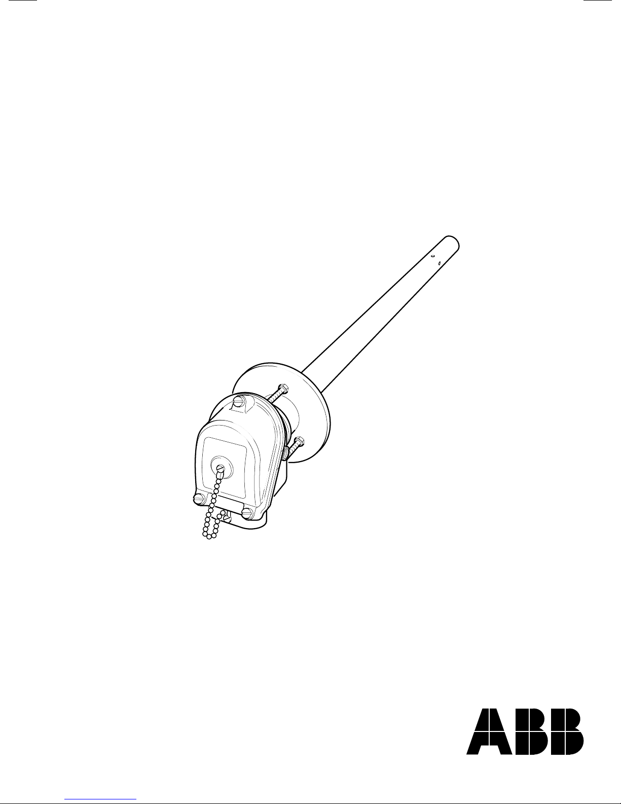
ABB Instrumentation
EXGP
Oxygen Analyzer System
Installation Guide
EXGP Probe
Page 2
ABB INSTRUMENTATION
✶
Note.
Clarification of an instruction or additional information.
Information.
Further reference for more detailed information or
technical details.
Although Warning hazards are related to personal injury, and Caution hazards are associated with equipment or property damage,
it must be understood that operation of damaged equipment could, under certain operational conditions, result in degraded
process system performance leading to personal injury or death. Therefore, comply fully with all Warning and Caution notices.
Information in this manual is intended only to assist our customers in the efficient operation of our equipment. Use of this manual
for any other purpose is specifically prohibited and its contents are not to be reproduced in full or part without prior approval of
Technical Communications Department, ABB Instrumentation.
The Company
ABB Instrumentation is an established world force in the design and manufacture of
instrumentation for industrial process control, flow measurement, gas and liquid analysis and
environmental applications.
As a part of ABB, a world leader in process automation technology, we offer customers
application expertise, service and support worldwide.
We are committed to teamwork, high quality manufacturing, advanced technology and
unrivalled service and support.
The quality , accuracy and performance of the Company’s products result from over 100 years
experience, combined with a continuous program of innovative design and development to
incorporate the latest technology.
The NAMAS Calibration Laboratory No. 0255 is just one of the ten flow calibration plants
operated by the Company, and is indicative of ABB Instrumentation’s dedication to quality
and accuracy.
BS EN ISO 9001
St Neots, U.K. – Cert. No. Q5907
Stonehouse, U.K. – Cert. No. FM 21106
EN 29001 (ISO 9001)
Lenno, Italy – Cert. No. 9/90A
Use of Instructions
Warning.
An instruction that draws attention to the risk of injury or
death.
Caution.
An instruction that draws attention to the risk of damage to
the product, process or surroundings.
Health and Safety
To ensure that our products are safe and without risk to health, the following points must be noted:
1. The relevant sections of these instructions must be read carefully before proceeding.
2. Warning labels on containers and packages must be observed.
3. Installation, operation, maintenance and servicing must only be carried out by suitably trained personnel and in accordance with the
information given.
4. Normal safety precautions must be taken to avoid the possibility of an accident occurring when operating in conditions of high pressure
and/or temperature.
5. Chemicals must be stored away from heat, protected from temperature extremes and powders kept dry. Normal safe handling procedures
must be used.
6. When disposing of chemicals ensure that no two chemicals are mixed.
Safety advice concerning the use of the equipment described in this manual or any relevant hazard data sheets (where applicable) may be
obtained from the Company address on the back cover, together with servicing and spares information.
0255
R
E
G
I
S
T
E
R
E
D
Stonehouse, U.K.
Page 3
1
CONTENTS
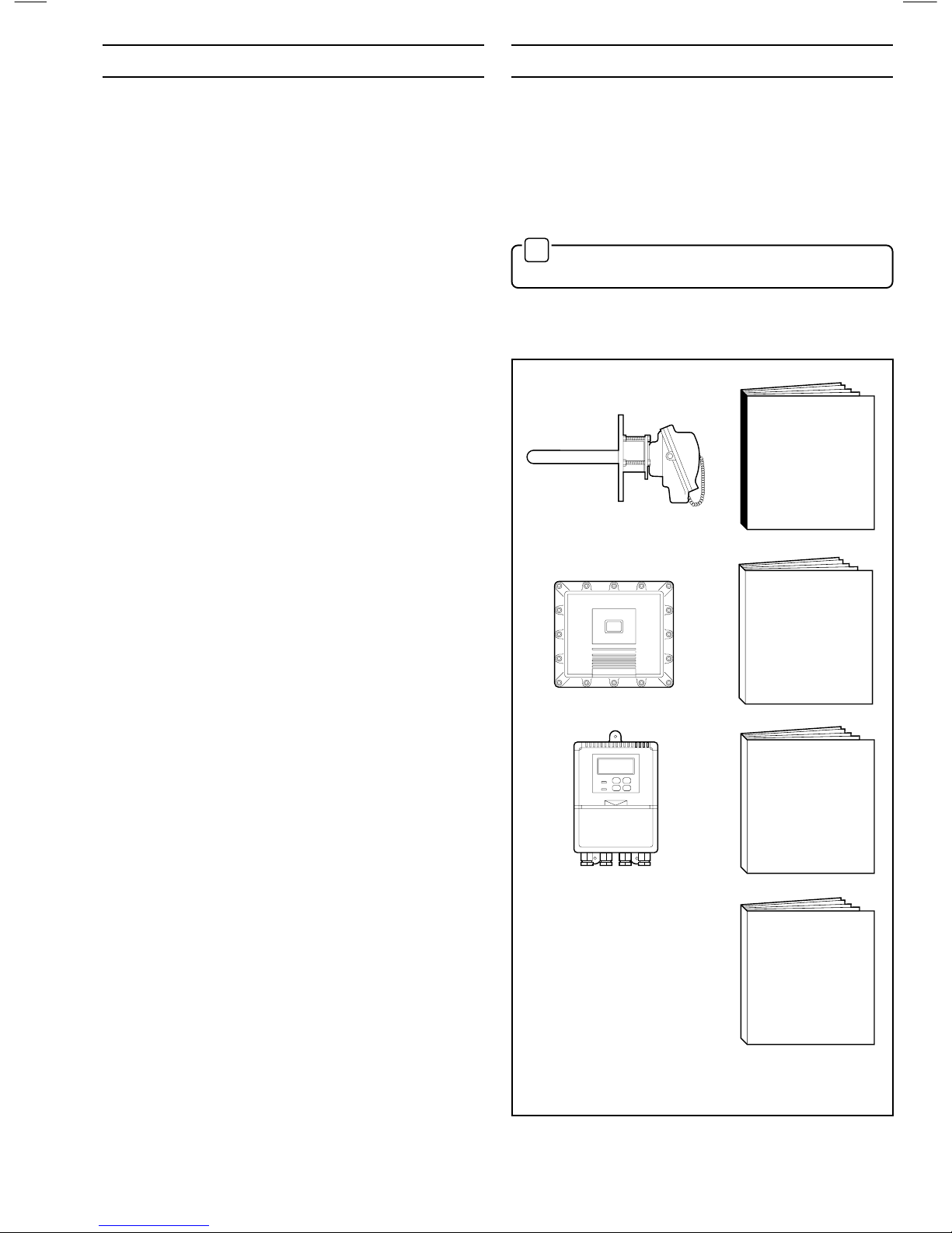
1.1 Documentation – Fig. 1.1
Documentation for the EXGP Oxygen Analyzer System is
shown in Fig. 1.1.
1.2 Certification
The EXGP Probe is classed as a 'Simple Apparatus' and may
therefore be installed in Zone 1 Hazardous Areas as an
intrinsically safe product.
✶
Note. A 'Simple Apparatus' is a device that does not
generate more than 1.2V, 0.1A, 20mJ and 25mW.
Documented evidence confirming the compliance of EXGP
Probes is available and is endorsed by BASEEFA.
Fig. 1.1 System Documentation
SPECIFICATION SHEET
Full Specification■
Part No.
SS/EXGP
PROBE
■
■
■
■
Part No.
IM/EXGP–PB
Product Identification
Mechanical Installation
Connections
Fault Finding
INTERFACE UNIT
Certification
Product Identification
Mechanical Installation
Electrical Installation
■
■
■
■
Part No.
IM/EXGP–INT
TRANSMITTER
Product Identification
Mechanical Installation
Electrical Connections
Controls & Displays
Operation
Programming
■
■
■
■
■
■
Part No.
IM/EXGP–4600
1 INTRODUCTION
1 INTRODUCTION ..........................................................1
1.1 Documentation ..................................................1
1.2 Certification .......................................................1
1.3 System Hardware..............................................2
2 PREPARATION ............................................................4
2.1 Unpacking .........................................................4
2.2 Checking the Code Number..............................4
2.3 Assembling the Probe .......................................5
3 INSTALLATION............................................................6
3.1 Siting..................................................................6
3.2 Mounting............................................................7
3.2.1 Mounting Configurations ..................... 8
4 CONNECTIONS ...........................................................9
4.1 Cable and Gland Specifications........................9
4.2 Access to Electrical Connections......................9
4.3 Electrical Connections ......................................9
4.4 Reference Air Connection .................................9
4.5 Routine Maintenance ........................................9
5 FAULT FINDING.........................................................10
5.1 In Situ Checking Using a Test Gas .................10
5.2 Comparison with Another O2 Probe ...............10
5.3 Returning the Probe
to the Manufacturer for Checking ...................10
5.4 Continuity Check .............................................10
APPENDIX...........................................................................11
A1 Principles of Operation....................................11
A2 Range of Operation.........................................11
Page 4

2
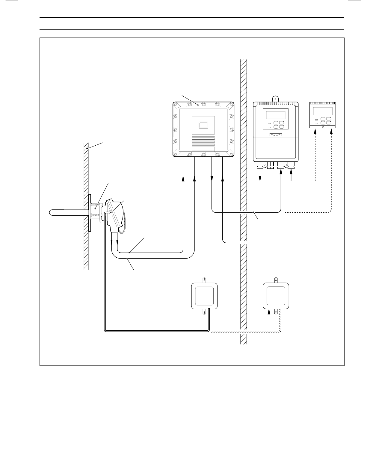
1.3 System Hardware – Fig. 1.2
The EXGP Oxygen Probe is an 'in situ' method of measuring
oxygen concentration designed for use in hazardous areas
(Zone 1). When used in conjunction with the EXGP Interface
Electronics Unit (also Zone 1 Certified), it enables signals to be
retransmitted up to 1km into a safe area.
The oxygen probe provides a mV signal that relates directly to
oxygen concentration in the range 0.25 to 25% O
2
, over a
process temperature range of 600°C to 1250°C. An integral 'R'
type thermocouple provides accurate continuous
measurement of the process temperature.
A calibration gas inlet port is provided to enable the probe to be
checked using test gas mixtures without removing it from the
process.
Reference air supplied at a rate of 100 to 1000cm
3
/hr (0.2 to
2ft
3
/hr) is required for accurate operation and can be provided
by a pump or regulator unit – see Fig. 1.2.
…1 INTRODUCTION
Page 5
3
Mains Powered Pump
Unit (003000240)
NON HAZARDOUS AREAHAZARDOUS AREA
(Zone 1, Class IIB)
Process
600°C to 1400°C
(1250°C
continuous)
EXGP Probe
Simple Device Conforming
to BS5345 Part 4: 1977
Mains Supply
R Type Thermocouple
mV Signal
(0 to 1400°C)
Two 4 to 20mA Output Signals
(0 to 1400°C and 0.25 to 25%O2)
or
4680 Transmitter
Mains Supply
Flameproof Interface Electronics Unit
EExd. IIB T6 Conforming to BS5501 Part 5: 1977
Flue
4685 Transmitter
Retransmission
Output
Reference Air Line Entry
Regulated Reference Air
Unit (003000241)
Mains Supply
O2 mV Signal
(–20 to +180mV)
or
or
1 INTRODUCTION
Fig. 1.2 System Schematic
Page 6
4
2.1 Unpacking
Caution. The probe is very fragile. Unpack and
handle with care.
Each probe is despatched with its components individually
placed within a common pack. Remove the probe from its
packing as follows:
a) Place the polystyrene pack, top uppermost, on a flat
surface and cut the tapes holding the two halves together.
b) Carefully lift the top half of the pack to gain access to the
probe components which are individually located within the
bottom half.
c) When removing the components from the pack take great
care to support the probe head and not to twist or bend the
electrode assembly attached to it.
d) Reassemble the packing and retain for future use.
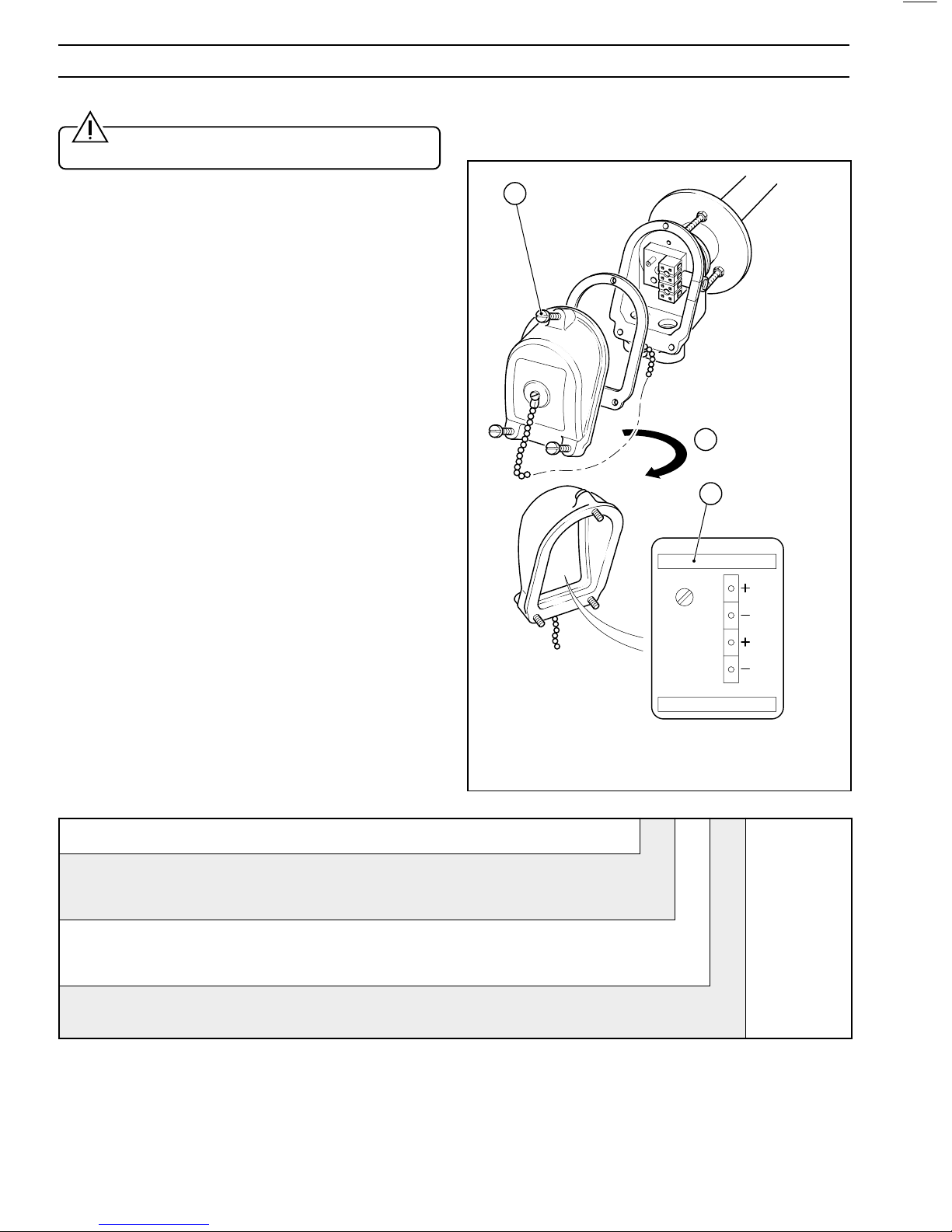
2.2 Checking the Code Number – Fig. 2.1
Before installing the equipment, check the code number on the
probe – see Fig. 2.1.
Code No.
TEST GAS
KEEP
TIGHTLY
CLOSED
WHEN NOT
IN USE
Serial No.
AIR
REF
THC
I/P
Remove cover
retaining screws (x3)
Rotate cover
Check probe code
number against
Table 2.1
1
2
3
eborPPGXE /PGXE XXX000
htgneL enoN
mm006
mm0001
laicepS
0
1
2
9
htaehS enoN
008yolocnI
nialecroPsuonimulA
laicepS
0
1
2
9
smetIdradnatS enoN
59CepyTdnalgniwT
)7394SBhR%31tP/tPelpuocomrehtepyt’R‘,detnuomegnalF(
0
1
2 PREPARATION
Fig. 2.1 Checking the Code Number
Table 2.1 Code Number Interpretation
Page 7
5
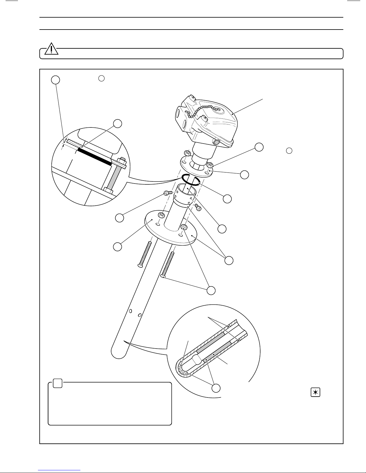
2.3 Assembling the Probe – Fig. 2.2
Caution. Take care to avoid damage to the probe when fitting the sheath assembly.
Wadding
Filter Washer
Vent
Holes
Secure countersunk-head screws (x3)
in fixing flange using the lock nuts (x3).
Position the clamp ring over the boss
on the probe head…
Position the sealing ring over the boss,
ensuring it is located correctly in
the centre taper.
Slide the fixing flange over the sheath,
ensuring it is seated over the
locating step.
Drill the fixing flange to
suit fixing requirements
Secure the sheath
to the boss (x3)
…ensuring the wadding at the probe
end is not damaged and the filter washer
is in position at the end of the sheath
…ensuring correct
orientation of the
ring's center taper
Locate the clamp ring over the
3 screws on the fixing flange
and secure using nuts (x3).
Tighten the nuts down equally so that the fixing flange is pulled down tightly against the locating step on the sheath
and the sealing ring is compressed until the adjacent faces of the clamp ring and sheath are 1 to 1.5mm apart.
Use a 1mm drill or shim to set the gap.
Probe Head
1 to 1.5 mm
Carefully insert the probe into the
ceramic sheath…
1
2
3
4
5
6
7
8
9
5
3
8
2
2 PREPARATION
✶
Note. To reduce its diameter the wadding
may be compressed slightly.
To increase its diameter, apply slight end
pressure on the wire bonding at both ends of the
wadding. Mould the wadding by hand to ensure
a light push fit into the sheath.
Fig. 2.2 Assembling the Probe
Page 8
6
Warning. The probe operates at high temperatures – take all necessary precautions to avoid injury through burns.
Caution. Thermal shock may damage the zirconia cell if the flue is cleaned using a high pressure water hose. If this
method of cleaning is used, remove the probe from the flue prior to cleaning. Never use the probe without the sheath.
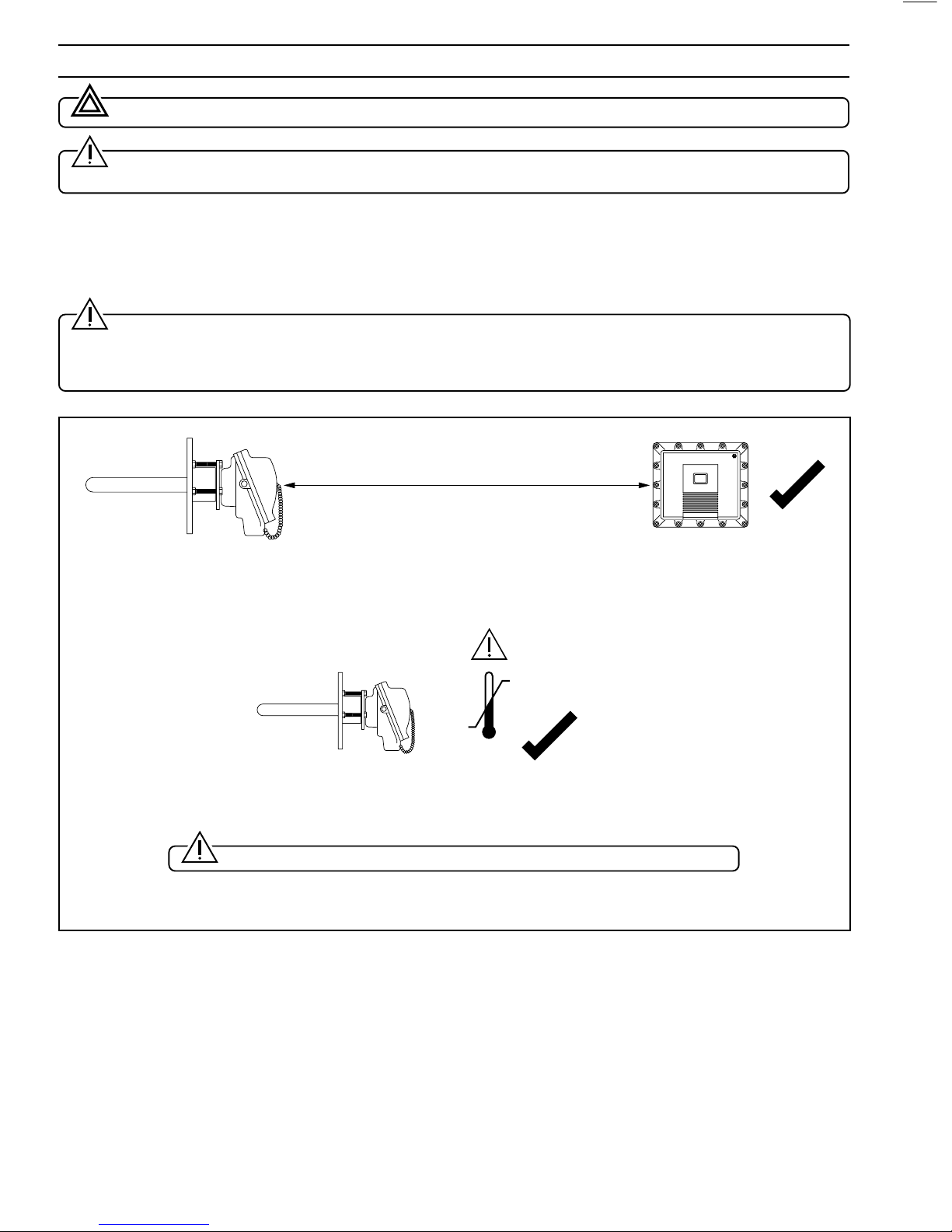
3.1 Siting – Fig. 3.1
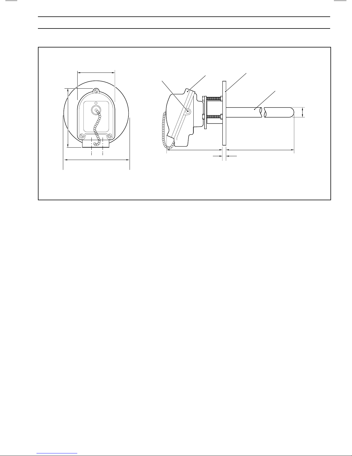
Select the position for the probe avoiding obstructions which may inhibit insertion or subsequent removal. Dimensions for the
probe are shown in Fig. 3.2. A clearance of at least 1in (25mm) in excess of the overall probe length is necessary for installation
or removal procedures.
Caution. The probe must not be sited:
• Where it would be subjected to mechanical or thermal shock.
• In the presence of aggressive compounds, e.g. molten slags, molten silicates, metals and vapors of lead, zinc, silicon and
vanadium.
1000°C Max. Incoloy Sheath
1250°C Max. Porcelain Sheath
600°C
Min.
B – Within Process Temperature Limits
Maximum Distance 230ft (70m)
A – Maximum Distance Between EXGP Probe and Interface Electronics Unit
ATMOSPHERE IS PRESENT
DO NOT OPEN WHEN FLAMMABLE
3 INSTALLATION
Caution. Reduced probe life may result if probe is operated above 1250°C.
Fig. 3.1 Siting
Page 9
7
3.2 Mounting – Figs. 3.2 and 3.3
Reference
Air Line
Entry
Connector Head
Mounting Flange
1.08
(27.5)
21.89 (556)
or
37.52 (953)
4.80 (122)
0.20 (5)
Probe Outer Sheath
Fixing holes in mounting flange
to be drilled by customer
Dimensions in inches (mm)
4.92
(125)
4.53
(115)
3.46 (88)
3 INSTALLATION…
Fig. 3.2 Overall Dimensions
Page 10
8
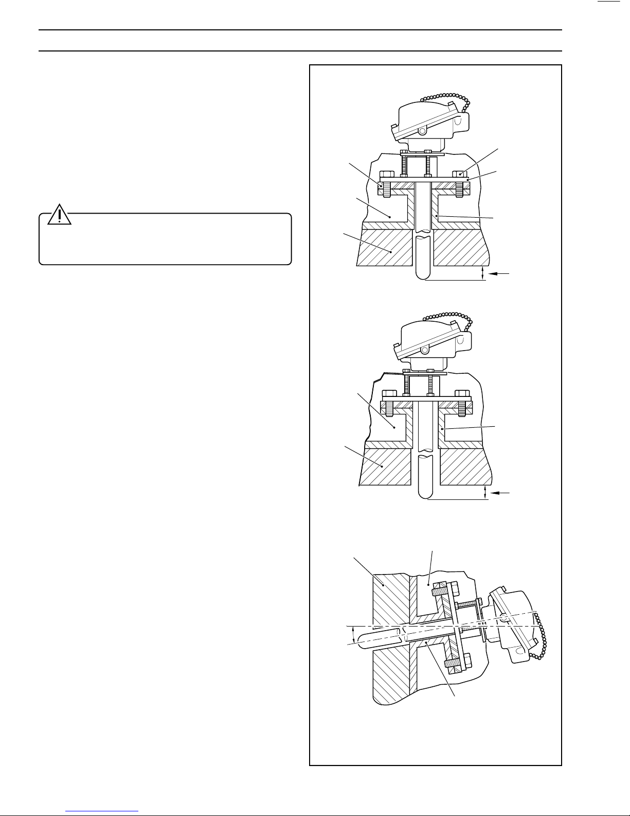
3.2.1 Mounting Configurations – Fig. 3.3
The probe may be fitted horizontally or, preferably, vertically
for prolonged high temperature operation.
Mount the probe through the furnace wall using the preferred
method shown in Fig. 3.3A. Ensure that a sufficiently large
hole is provided through the mounting – min. bore 1.65ins
(42mm) diameter – to avoid damage to the probe during
insertion or use.
Drill the fixing flange to suit the local fixing requirements before
assembling the probe – see Section 2.3.
Caution. To prevent furnace gas from
contaminating the reference air, always ensure that the
clamp ring, fixing flange and sealing ring are fitted to the
probe as described in Section 2.3.
With applications such as high temperature incinerators, fluid
bed boilers and ore roasters, where the level of water vapor in
the waste gases to be measured can be extremely high, it is
important that the mounting flange of the probe, including any
standoff which may be used, is thermally insulated to minimize
condensation within the probe – see Fig. 3.3A.
Condensation within the probe sheath, particularly in outdoor
installations, can be sufficient to allow water to come into
contact with the hot ceramic (zirconia) tube leading to thermal
shock and failure of the sensor. This problem is most likely to
occur on such installations where the plant is shut down
regularly over the weekend. Additionally, take care to protect
the head of the probe from the elements in outdoor
installations.
Raising the temperature of the probe as rapidly as possible
assists in reducing the level of condensation. This is not
possible on some processes where the plant temperature is
gradually raised to the normal operating level. The
temperature rise at the head of the probe can be assisted by
having a large clearance hole in the refractory allowing hot
gases to get up to the mounting flange/standoff – see Fig.
3.3B.
Horizontal installations are more likely to exhibit the problems
described. Where it is not possible to mount the probe in the
vertical position, install the probe with a slope of at least 10 to
15° downwards from the head of the probe – see Fig. 3.3C.
Clamp Bolt
Fixing Flange
Support Tube
and Flange
5.90
(150) min.
Furnace
Wall
Thermal
Insulation
Packing
A – Standard Configuration
Support Tube
and Flange
Thermal
Insulation
Furnace
Wall
5.90
(150) min.
B – Improved Probe Heating
Support Tube
and Flange
Thermal
Insulation
Furnace Wall
10° Min.
C – Inclined Configuration
Dimensions in inches (mm)
…3 INSTALLATION
Fig. 3.3 Probe Mounting
Page 11
9
Reference Air Input
2 Cable Entries, Threaded M16
+ Thermocouple
– Thermocouple
+ Cell Input (Inner)
– Cell Input (Outer)
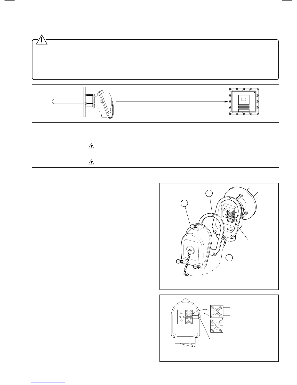
4.2 Access to Electrical Connections – Fig. 4.1
For access to the terminal block – see Fig.4.1.
4.3 Electrical Connections – Fig. 4.2
Make connections as shown in Fig. 4.2 and on the label inside
the probe head cover. The connecting cable must enter the
probe head via the two M16 cable glands.
4.4 Reference Air Connection – Fig. 4.2
The reference air connector is 1/8in. BSP fitted with an adaptor
to accept
1
/4in i.d. x 3/8in o.d. nylon or PVC tubing (100°C
ambient maximum).
The probe requires clean, dry air supplied at 100 to 1000cm
3
/hr
(0.2 to 2ft
3
/hr). The air may be regulated instrument air or
preferably atmospheric air from a small pump unit. Suitable air
supply units are available from the Company:
a) Model 003000240 – mains powered pump unit with flow
gauge for use in safe areas only.
b) Model 003000241 – regulated air supply unit for use in
both safe and hazardous areas.
4.5 Routine Maintenance
No maintenance is necessary, or possible, on the probe and
any attempt to dismantle it could cause irreparable damage.
The probe can be tested for accuracy whilst connected to its
measuring system but without removal from its operating
position.
It is recommended that at least one spare probe is held for
replacement or comparison purposes.
Remove
cover
retaining
screws (x3)
Remove gasket
Identify terminal block
Test Gas Connector
(with screwed plug)
1
2
3
4 CONNECTIONS
Table 4.1 Cable and Gland Specifications (electrical requirements only)
eborP–noitacificepSdnalG )slangiSefaSyllacisnirtnI(noitacificepSelbaC ecafretnI–noitacificepSdnalG
deifitrec-noN61M
llarevo,eroc-2,2.0/61:tupnI)Vm(elpuocomrehTepyTR
7394SBotelbacgnitasnepmocelpuocomrehtepyt-R,neercs
3ecnaticapaC µ 82oitaRR/L,Hm72.0ecnatcudnI,f µ /H Ω
'd'dnalgreirrabdeifitreCAFEESAB02M
)foorpemalf(
deifitrec-noN61M
deneercsllarevo,reppoceroc-2,2.0/61:tupnI)Vm(negyxO
3ecnaticapaC µ 82oitaRR/L,Hm72.0ecnatcudnI,f µ /H Ω
'd'dnalgreirrabdeifitreCAFEESAB02M
)foorpemalf(
ATMOSPHERE IS PRESENT
DO NOT OPEN WHEN FLAMMABLE
Fig. 4.1 Access to Electrical Connections
Fig. 4.2 Connections
4.1 Cable and Gland Specifications – Table 4.1
Caution. Cables and glands are not supplied with the probe and must conform to the following requirements:
• The Capacitance and Inductance or Inductance to Resistance (L/R) ratio of the cables connected to the output (hazardous
area terminals) of the zener barriers mounted in the EXGP Interface Electronics Unit must not exceed the values shown.
• All cables must conform to BS5345 for flameproof 'd' type enclosures for mechanical construction.
• EEx d glands used on the Interface Electronics Unit must be of the EEx d 'Barrier Gland' type with BASEEFA certification
because the enclosure is over 2 litres volume, has a source of ignition within and is designed for use in Zone 1 areas
(reference BS5345 part 3).
Page 12

10
5.2 Comparison with Another O2 Probe
The probe may be checked by comparison with another of
known reliability , either by replacing the suspect probe with the
known probe or by mounting the known probe in close
proximity and monitoring both probes continuously for a short
period.
5.3 Returning the Probe
to the Manufacturer for Checking
If it is not possible to carry out the above tests on site and
failure or malfunction is suspected, the probe may be returned
to the Company for checking.
If returning the probe, carefully dismantle the probe
components by reversing the procedure detailed in Fig. 2.2.
Repack in the original packing to ensure safe carriage.
5.4 Continuity Check
Connect a 100kΩ resistor across the probe output. If the
output drops to near zero millivolts and then drifts when the
resistance is removed, this indicates that the probe may be
open circuit or have a high impedance.
Warning. The probe operates at high
temperatures. Take all necessary precautions to avoid
injury through burns.
During its working life, under normal recommended
conditions, the probe output remains accurate and without
drift. However, probe malfunctions can result from a fault in the
probe or from incorrect operating conditions.
The testing of a suspect probe can only be carried out
satisfactorily in its working position or in a furnace controlled
within the normal probe operating temperature range.
If a probe failure is suspected, first perform a test gas check as
described in the following sections.
5.1 In Situ Checking Using a Test Gas
This procedure introduces a test gas of known O
2
concentration around the outer electrode of the probe in the
space between the filter washer, at the bottom of the sheath,
and the wadding around the lower end of the probe. Four vent
holes (see Fig. 2.2) prevent the gas from being trapped in the
upper part of the sheath.
a) Gain access to the interior of the probe head by
unscrewing the lid fixing screws – see Fig. 4.1.
b) Remove the screwed plug from the test gas connector –
see Fig. 4.1.
c) Fit
1
/4in i.d. x 3/8in o.d. plastic or similar tubing and supply a
test gas of known oxygen between 0.25 and 25% O
2
concentration to the probe at a steady flow rate of 800 to
1000ml/min. Allow at least 5 minutes for the system to
stabilize before making a measurement.
d) Check that the oxygen concentration measured by the
4680 or 4685 transmitter (mounted in a safe area),
compares with the specification for the test gas used.
✶
Note. The O2 concentration measured by the
probe can be checked locally by taking readings from
the probe thermocouple (for temperature) and the
cell O
2
mV input and entering the results in to the
Nernst Equation.
e) Disconnect the test gas and ensure that the screwed plug
is replaced in the test gas connector. Failure to do this may
result in serious measurement errors due to the entry of air
into the probe.
f) Proceed to Table 5.1.
5 FAULT FINDING
tseTfotluseR
kcehCsaG
foesuaCelbissoP
noitcnuflaMnoitarepOnoitcA
tcerroC—enoN
tcerrocnIylppusriaecnerefeR
Ohgih(eruliaf
2
)gnidaer
ecnerefereborpkcehC
ylppusria
tinuscinortceleytluaF
rotacidniro
fonoitarepokcehC
denrecnocstinu
ebutainocriznikaeL
nekorbroeborpnihtiw
ebutainocriz
Ohgih(
2
)gnidaer
htiwnoitarepoerapmoC
Orehtona
2
–ebut
yrassecenfiecalper
gnitfirdrooreZ
htiwsgnidaer
otesnopseron
sagtset
lleceborptiucricnepO
snoitcennoc
ytiunitnocatuoyrraC
4.5noitceSees–kcehc
tinuscinortceleytluaF
snoitcennocrorotacidni
fonoitarepokcehC
denrecnocstinu
Table 5.1 Fault Finding
Page 13
11
A1 Principles of Operation
The EXGP probe comprises a ceramic detector cell housed in
a protective sheath. A thermocouple is fitted within the probe to
enable the process temperature to be monitored or for
automatic temperature compensation to be provided.
The sheath material may be either aluminous porcelain
(recommended for oxidizing atmospheres) or Incoloy 800
(recommended for reducing atmospheres) for use at
maximum temperatures of 1250°C and 1000°C respectively.
Special sheaths are available for use up to 1400°C.
Connections for the cell output, thermocouple and reference
air are all made at the probe connector head.
The probe contains a high temperature oxygen concentration
cell using zirconium oxide as a solid electrolyte. Inner and
outer electrodes are attached to the cell which is specific to
oxygen.
Air is supplied to the inner reference electrode to provide a
constant partial pressure of oxygen while the process gas to
be measured is in contact with the outer electrode.
A voltage is generated across the electrodes which is a
function of the ratio of the oxygen partial pressures at the two
electrodes. This voltage output represents 'oxygen potential'
and can be used to control the atmosphere of annealing
processes etc.
For the measurement of 'oxygen concentration' it is necessary
to correct for absolute temperature of the probe. The
temperature term in the Nernst equation, on which the voltage
output depends, illustrates this point:
Nernst Equation
E = 0.0496 T (log10 P0/P1) + C mV
Where:
T = Absolute Temperature (°K)
P
0
= Partial Pressure Reference Gas
P
1
= Partial Pressure Sample Gas
C = Cell Constant
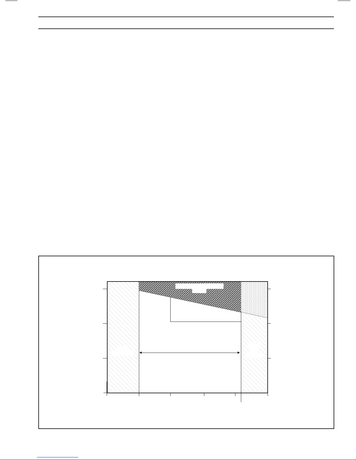
A2 Range of Operation – Fig. A1
The internal resistance of the cell, i.e. the resistance of the
electrolyte between the electrodes, decreases approximately
exponentially with increasing temperature and for this reason
it is recommended that the probe is used at temperatures
greater than 600°C.
The maximum operating temperature is limited by two factors:
a) The onset of electronic conduction through the electrolyte
which reduces the measured output below its theoretical
value.
b) Evaporation of the outer electrode.
Electronic conduction is a function of both temperature,
oxygen partial pressure and, for stabilized zirconia, it occurs at
low levels of oxygen and high temperature. For the above
reasons it is recommended that the probe is used at
temperatures between 600°C and 1250°C – see Fig. A1.
Electronic Conduction
Errors
High
Resistance
Normal Operation
Non-carburising
Atmospheres only
400 600 800 1000 1200
1250
1400
150
100
50
Kilocalories
Probe
Output
mV
1500
500
1000
Degrees Celsius
Pt/Pt 13% Rh Thermocouple
Probe
Life
Reduced
APPENDIX
Fig. A1 Range of Operation
Page 14

12
NOTES
Page 15

PRODUCTS & CUSTOMER SUPPORT
A Comprehensive Instrumentation Range
Analytical Instrumentation
• Transmitters
On-line pH, conductivity, and dissolved oxygen
transmitters and associated sensing systems.
• Sensors
pH, redox, selective ion, conductivity and dissolved
oxygen.
• Laboratory Instrumentation
pH and dissolved oxygen meters and associated
sensors.
• Water Analyzers
For water quality monitoring in environmental, power
generation and general industrial applications including:
pH, conductivity, ammonia, nitrate, phosphate, silica,
sodium, chloride, fluoride, dissolved oxygen and
hydrazine.
• Gas Analyzers
Zirconia, katharometers, hydrogen purity and purge-gas
monitors, thermal conductivity.
Controllers & Recorders
• Controllers
Digital display, electronic, pneumatic. Discrete singleloop and multi-loop controllers which can be linked to a
common display station, process computer or personal
computer.
• Recorders
Circular and strip-chart types (single and multi-point) for
temperature, pressure, flow and many other process
measurements.
Electronic Transmitters
• Smart & Analog Transmitters
For draft, differential, gauge and absolute pressure
measurement. Also, liquid level and temperature.
• I to P Converters and Field Indicators
Flow Metering
• Magnetic Flowmeters
Electromagnetic, insertion type probes and watermeters.
• Turbine Flowmeters
• Wedge Flow Elements
• Mass Flow Meters
Transmitters, sensors, controllers and batch/display
units.
Level Control
• Submersible, Capacitance & Conductivity.
Pneumatic Instrumentation
• Transmitters
• Indicating Controllers
• Recording Controllers
Customer Support
ABB Instrumentation provides a comprehensive after sales
service via a Worldwide Service Organization. Contact one of
the following offices for details on your nearest Service and
Repair Centre.
United Kingdom
ABB Instrumentation Ltd
Tel: +44 (0)1480 475321
Fax: +44 (0)1480 470787
United States of America
ABB Automation Inc.
Instrumentation Division
Tel: +1 215-674-6000
Fax: +1 215-674-7183
Italy
ABB Instrumentation SpA
Tel: +39 (0) 344 58111
Fax: +39 (0) 344 58278
Client Warranty
Prior to installation, the equipment referred to in this manual
must be stored in a clean, dry environment, in accordance with
the Company's published specification. Periodic checks must be
made on the equipment's condition.
In the event of a failure under warranty, the following
documentation must be provided as substantiation:
1. A listing evidencing process operation and alarm logs at time
of failure.
2. Copies of operating and maintenance records relating to the
alleged faulty unit.
Page 16

IM/EXGP–PB Issue 3
The Company’s policy is one of continuous product
improvement and the right is reserved to modify the information
contained herein without notice.
© ABB 2000 Printed in UK (05.00)
ABB Instrumentation Ltd
St. Neots
Cambs.
England, PE19 8EU
Tel: +44 (0) 1480 475321
Fax: +44 (0) 1480 217948
ABB Automation Inc.
Instrumentation Division
125 E. County Line Road
Warminster, PA 18974 USA
Tel: +1 215-674-6000
Fax: +1 215-674-7183
ABB Instrumentation SpA
22016 Lenno
Como
Italy
Tel: +39 (0) 344 58111
Fax: +39 (0) 344 58278
 Loading...