

Page 1
eOT Series
Enclosed Manual Motor Controllers
Catalog number: eOT16_, eOT25_, eOT32_, eOT45_, eOT63_
1SCC340019M0202
Installation and maintenance instructions
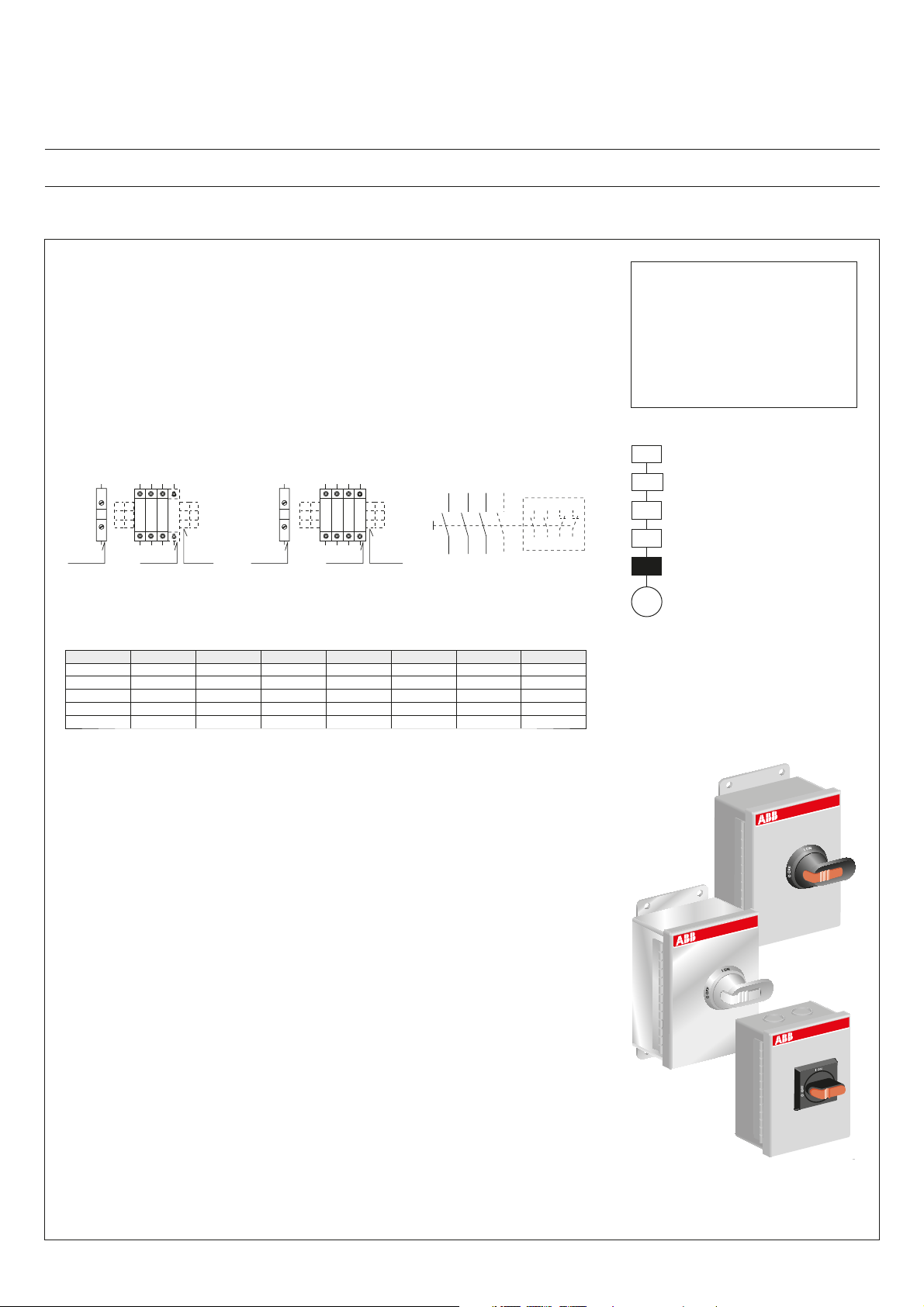
Applications
The eOT series enclosed manual motor controllers are rotary operated, 3 or 4
pole, 600V Heavy Duty switches, housed in metallic enclosures. Available in UL
environmental ratings Type 1, Type 3R & 12 with selector and pistol grip handles
and in Type 4X with pistol grip handles. Products are properly installed on the
load side of a branch circuit protective device and are marked “Suitable as
Motor Disconnect”.
eOT16-63 Non-Fused
Disconnect up to 600 VAC 3ø
A00241A
1L1 5L33L2
21
31
G
22
32
neutral busground bus
4313
14 44
6T34T22T1
auxiliary
contacts
Ratings
eOT16-63 Non-Fused
Disconnect up to 600 VAC 3ø
+ neutral pole
1L1 5L33L2
21
22
6T34T22T1
neutral bus
(N)
4313
7L4
(N)
14 44
8T4
auxiliary
contacts
ground bus
31
G
32
1 3 5 N(7)
13 43 21
14 44 22
2 4 6 N(8)
Document no. 34 EOT 16-63 M/S B
WARNING
To avoid hazard of electric
shock, turn off and lock out all
power sources before installing
or performing maintenance on
this equipment.
Disconnecting means
Short circuit protective device
31
32
Controller
Overload protection
Motor disconnection
M
P/N AMPS VAC 200V 208V 240V 480V 600V
eOT16_ 16A HP 3 3 5 10 10
eOT25_ 25A HP 7.5 7.5 7.5 15 20
eOT32_ 40A HP 10 10 10 10 10
eOT45_ 60A HP 15 15 15 30 30
eOT63_ 80A HP 20 20 20 40 40
Wire connections
eOT16-32:
Switch wire range: #18-8 AWG, 60-75 °C, Cu only, solid or stranded
Torque: 7 lbs/in, use Pozi-drive #2 or fl at blade screwdriver
eOT45-63:
Switch wire range: #14-4 AWG, 60-75 °C, Cu only, solid or stranded
Torque: 18 lbs/in, use Pozi-drive #2 or fl at blade screwdriver
Auxiliary contacts, 10A, 600V, A600-R300
Switch wire range: #18-14 AWG, 60-75 °C, Cu only, solid or stranded
Torque: 7 lbs/in, use Pozi-drive #2 or fl at blade screwdriver
Optional Power Poles
eOT16-32:
OTPS40FPN2 4th pole
OTPN40FP Solid neutral pole
eOT45-63:
OTPS80FP 4th pole
OTPN80FP Solid neutral pole
Optional Auxiliary contacts
OA1G10 (1 N.O.) Install on right side of switch. Max. 2 pcs on 3-pole
switch, 1 pcs on 4-pole switch (eOT16-32)
OA1G01 (1 N.C.) Install on left side of switch. Max. 2 pcs.
A00236A
Page 2

eOT Series Enclosed Manual Motor Controllers
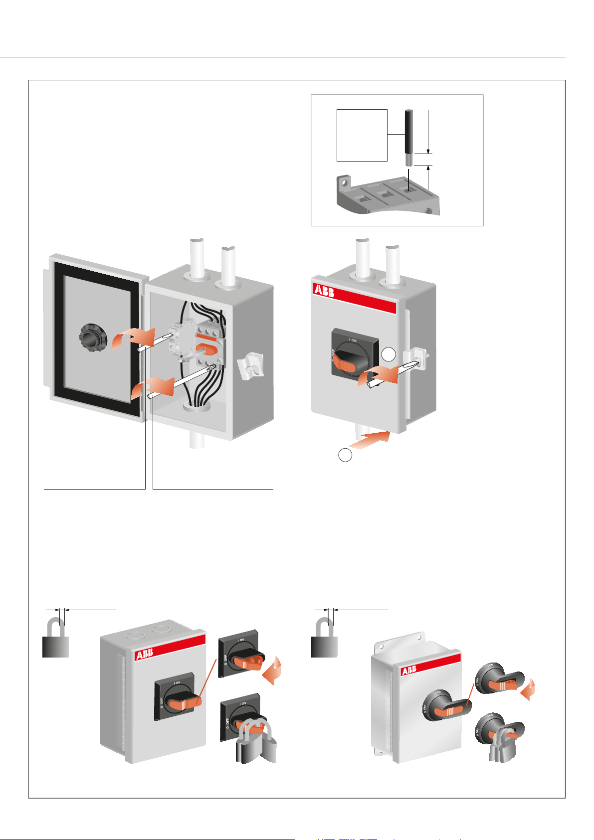
Installation
Operate switch to the OFF position and loosen the lock.
Open the enclosure.
eOT16-32
Two concentric 1/2" & 3/4" K.O.s are provided in the top
and bottom of the enclosure of Type 1. Type 3R & 12 and
Type 4X not equipped with K.O.s.
eOT45-63
Two concentric 1/2" & 3/4" and one concentric 3/4" & 1"
K.O.s are provided in the top and bottom of the enclosure
of Type 1. Type 3R & 12 and Type 4X not equipped with
K.O.s.
2
1
A00231A
3
A00243A
A00232A
A00242A
Drill proper holes for conduit hubs or use K.O.s. Protect
switch from drilling debris. Install conduit hubs.
Install enclosure using (4) 1/4” or M6 screws.
Page 3
Wiring
Connect power wires to switch terminals and attach
ground wire to the ground terminal block inside the
enclosure. Reference the National Electric Code and
all local codes for appropriate wire size and grounding
requirements.
Close the enclosure door, note that both the switch and
the operating handle on the door must be in the OFFposition. Tighten the lock’s screw.
eOT16...32:
0,75...10mm
18...8 AWG
eOT45...63:
1,5...25 mm
14...4 AWG
A07199
eOT16...32:
2
2
9-10 mm
0,35 - 0,39 in
eOT45...63:
10 - 12 mm
0,39 - 0,47 in
2
Pozi-drive #2 or flat blade screwdriver
eOT16-32: Torque 7 lbs/in
Ground terminal block:
Torque 7 lbs/in
eOT45-63: Torque 18 lbs/in
Auxiliary contacts: Torque 7 lbs/in
Operating handle
Operating handle may be padlocked in the OFF-position
with up to three padlocks. When locked, the enclosure
door is interlocked and can not be opened. All padlocks
must be removed to gain entry to the enclosure.
Ø 5...8 mm / 0.20...0.32 in
A00233A
A00234A
1
Ø 5...10 mm / 0.20...0.39 in
A00235A
Page 4
eOT Series Enclosed Manual Motor Controllers
mm
in
A
D
ONI
B
C
E
A07200 / M00102 / EOT16-32M/S-S B
O OFF
F
G
19
0,75
H
J
I
K
L
38,1
1,50
3/4"
1/2"
Type 1
38,1
1,50
Type 3R, 4X, 12
M
N
50,8
38,1
2,00
1,50
P
38,1
1,50
O
34,9
1,38
3/4"
1/2"
41,3
1,63
41,3
1,63
34,9
1,38
1 "
3/4 "
eOT16-32 eOT45-63
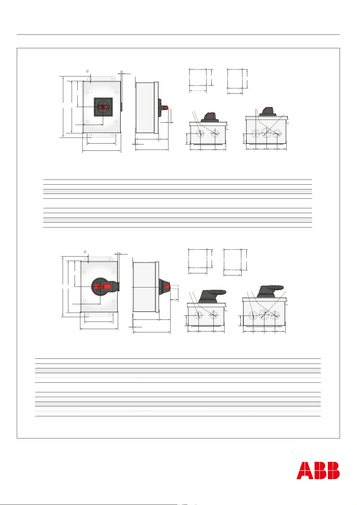
Knock-outs in top and bottom of type 1 enclosures
eOT16-32
Dimension [mm/in]
A B C D E F G H I J K L M N O P
7,9/0,31 215,9/8,50 183,4/7,22 91,7/3,61 73,7/2,90 101,6/4,00 134,1/5,28 19,0/0,75 83,3/3,28 35,5/1,36 2,8/0,11 117,9/4,64 101,6/4,0 101,6/4,0 196,9/7,75 76,2/3,00
eOT45-63
Dimension [mm/in]
A B C D E F G H I J K L M N O P
7,9/0,31 241,3/9,50 208,8/8,22 104,4/4,11 86,1/3,39 127,0/5,00 159,5/6,28 19,0/0,75 108,7/4,28 34,5/1,36 2,8/0,11 143,3/5,64 127,0/5,0 127,0/5,0 222,3/8,75 101,6/4,00
mm
in
A
D
B
C
E
A07201 / M00101 / EOT16-32M/S-P B
F
G
19
0,75
I
J
K
L
Type 1 Type 3R, 4X, 12
M
N
3/4"
1/2"
H
38,1
1,50
38,1
50,8
1,50
2,00
eOT16-32
38,1
1,50
P
38,1
1,50
O
3/4"
1/2"
34,9
1,38
41,3
41,3
1,63
1,63
eOT45-63
34,9
1,38
1 "
3/4 "
Knock-outs in top and bottom of type 1 enclosures
eOT16-32
Dimension [mm/in]
Handle code A B C D E F G H I J K L M N O P
-P 7,9/0,31 215,9/8,50 183,4/7,22 91,7/3,61 73,7/2,90 101,6/4,00 134,1/5,28 36,6/1,42 83,3/3,28 45,0/1,77 2,8/0,11 128,3/5,05 101,6/4,0 101,6/4,0 196,9/7,75 76,2/3,00
-M 7,9/0,31 215,9/8,50 183,4/7,22 91,7/3,61 73,7/2,90 101,6/4,00 134,1/5,28 36,6/1,42 83,3/3,28 52,0/2,05 2,8/0,11 135,5/5,33 101,6/4,0 101,6/4,0 196,9/7,75 76,2/3,00
eOT45-63
Dimension [mm/in]
Handle code A B C D E F G H I J K L M N O P
-P 7,9/0,31 241,3/9,50 208,8/8,22 104,4/4,11 86,1/3,39 127,0/5,00 159,5/6,28 36,0/1,42 108,7/4,28 45,0/1,77 2,8/0,11 153,7/6,05 127,0/5,0 127,0/5,0 222,3/8,75 101,6/4,00
-M 7,9/0,31 241,3/9,50 208,8/8,22 104,4/4,11 86,1/3,39 127,0/5,00 159,5/6,28 36,0/1,42 108,7/4,28 52,0/2,05 2,8/0,11 160,7/6,32 127,0/5,0 127,0/5,0 222,3/8,75 101,6/4,00
ABB Inc. / USA
16250 W. Glendale Drive
New Berlin, WI 53151
www.abb.com/us
ABB Inc. / CANADA
2117, 32nd Avenue
Lachine, QC H8T 3J1
www.abb.com/ca
 Loading...