

Page 1
Data sheet
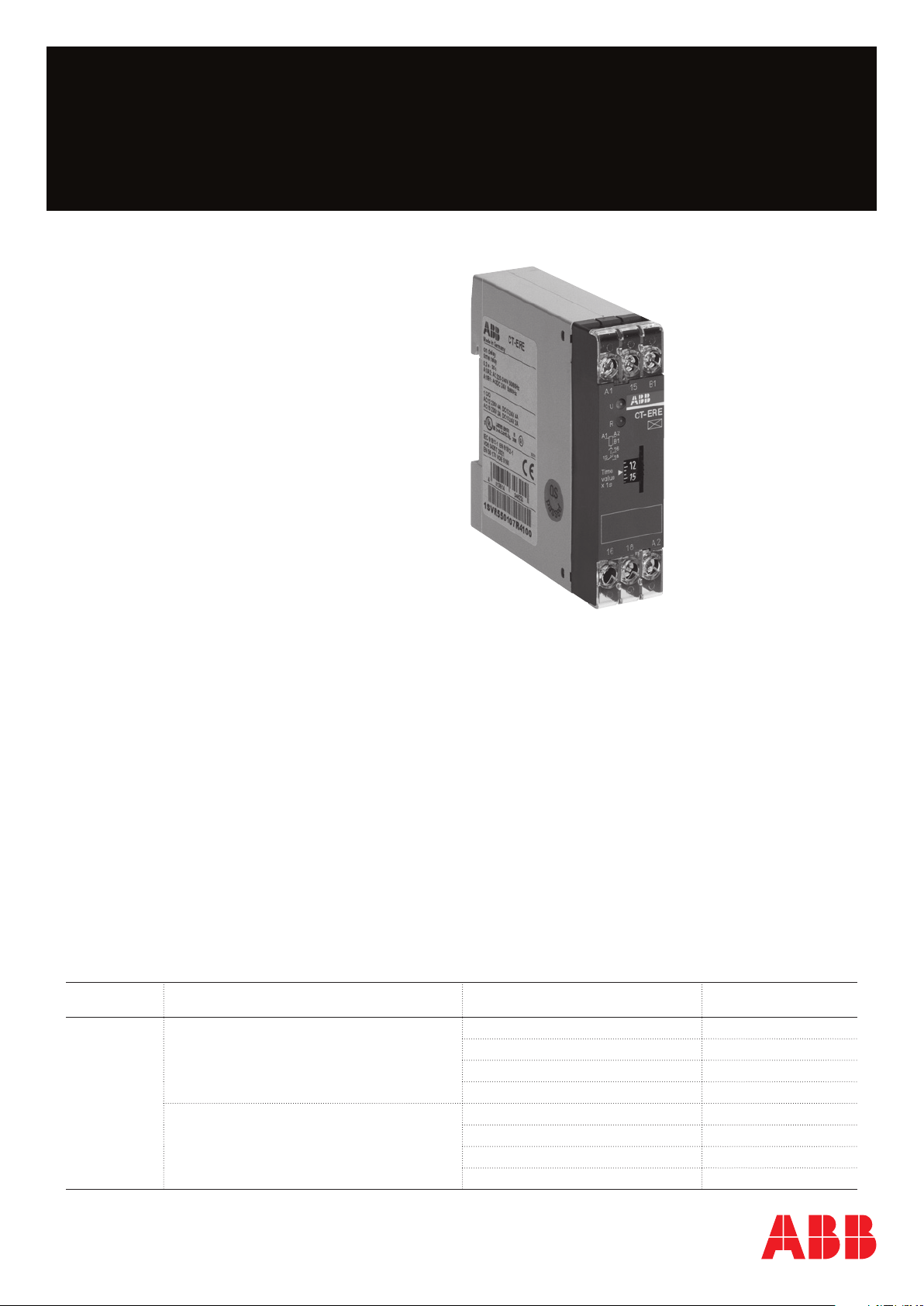
Electronic timer CT-ERE
ON-delayed with 1 c/o (SPDT) contact
The CT-ERE is an electronic time relay with
ON-delay. It is from the CT-E range.
The CT-E range is the economic range of ABB‘s
time relays and offers a cost effective
price-performance ratio for OEM users. This is
achieved by simplified functionality and results in
the simplest of setup procedures. The CT-E range
is ideally suited for repeat applications.
1SVR 550 107 F4100
Characteristics
– 8 versions:
4 different single time ranges (0.1-10 s, 0.3-30 s, 3-300 s and 0,3-30 min) and
2 different rated control supply voltage ranges (24 V AC/DC / 220-240 V AC and 110-130 V AC)
– Single-function ON-delay timer
– 1 c/o (SPDT) contact
– 22.5 mm (0.89 in) width
– 2 LEDs for the indication of operational states
Order data
Type Rated control supply voltage Time range Order code
CT-ERE 24 V AC/DC, 220-240 V AC
110-130 V AC 0,1-10 s 1SVR 550 100 R1100
0,1-10 s
0,3-30 s 1SVR 550 107 R4100
3-300 s 1SVR 550 107 R2100
0,3-30 min 1SVR 550 107 R5100
0,3-30 s 1SVR 550 100 R4100
3-300 s 1SVR 550 100 R2100
0,3-30 min 1SVR 550 100 R5100
1SVR 550 107 R1100
Page 2
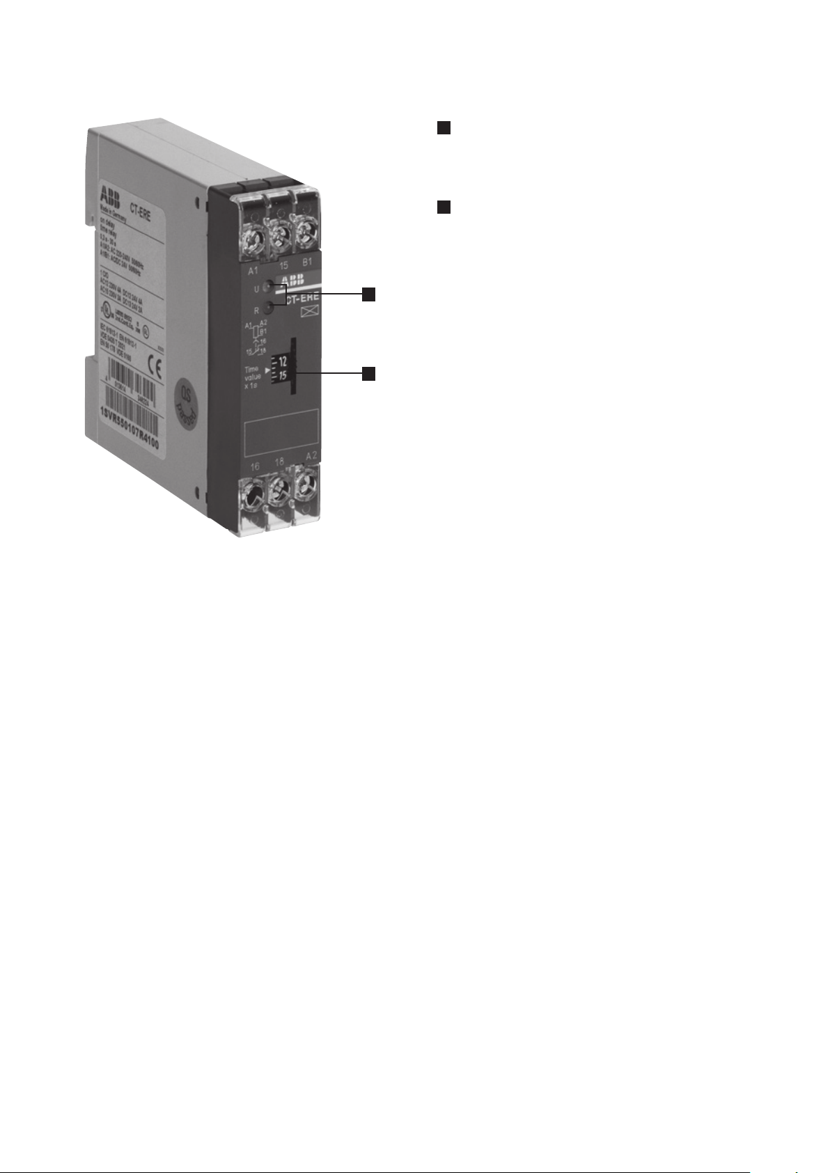
Functions
Operating controls
1SVR 550 107 F4100
1
Indication of operational states
U: green LED – Control supply voltage applied
R: red LED – Output relay energized
2
Thumbwheel for the fine adjustment of the time delay
1
2
Application
Their conception makes the CT-E range timers ideal for repeat applications.
Operating mode
The fine adjustment of the time delay is made via the front-face thumbwheel.
2 - Electronic timer CT-ERE | Data sheet
Page 3
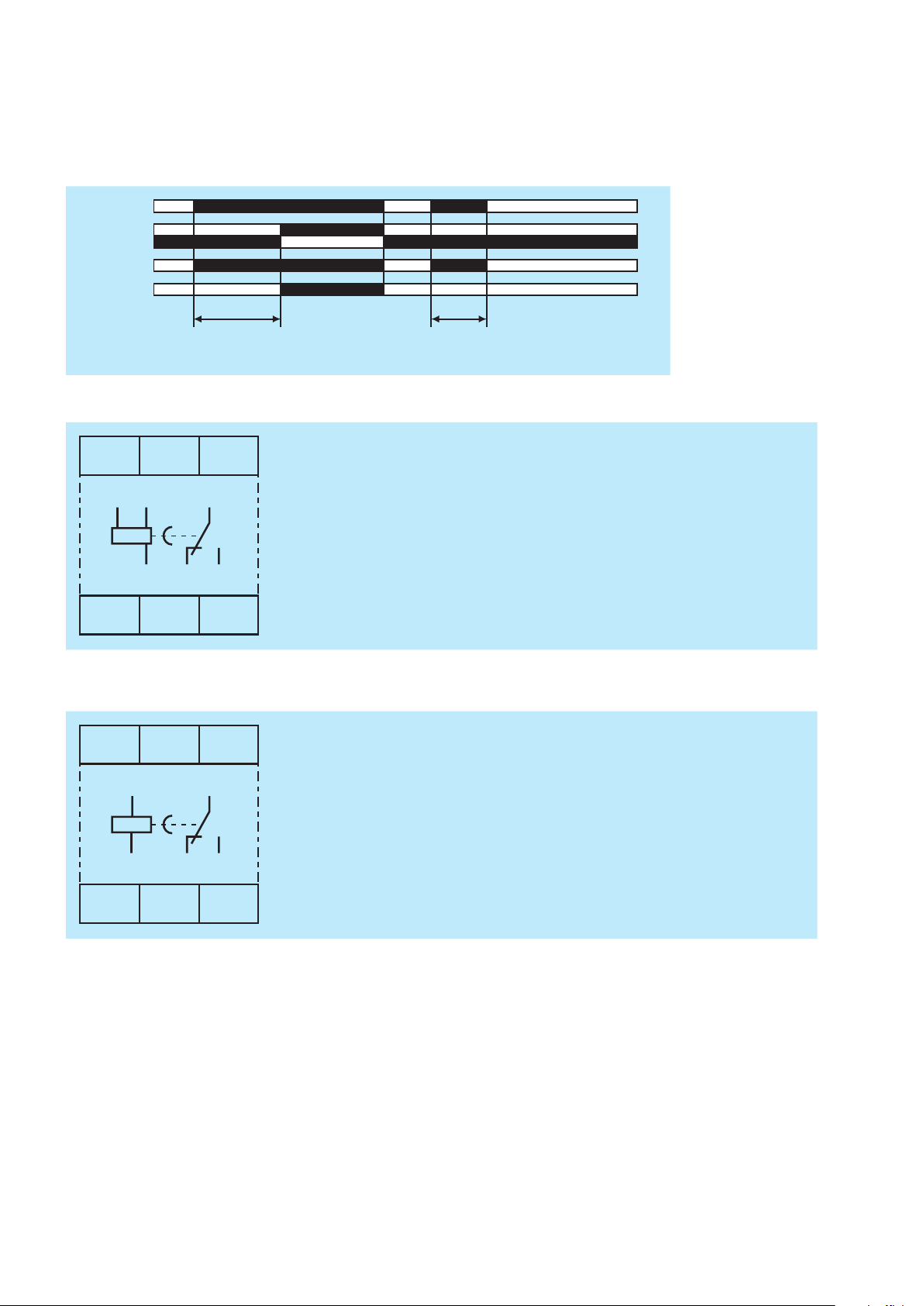
Function diagram
A1-A2/B1
gr
A ON-delay (Delay on make)
Applying control supply voltage starts timing. When the selected time delay is complete, the output relay energizes. If
control supply voltage is interrupted, the output relay de-energizes and the time delay is reset. Interrupting control supply
voltage before the time delay is complete, resets the time delay. The output relay does not energize.
15-18
15-16
een LED
red LED
t = adjusted delay time
Electrical connection
A1 15
A1 B1
15
B1
t
A1-A2 Rated control supply voltage Us: 220-240 V AC
A1-B1 Rated control supply voltage Us: 24 V AC/DC
15-16/18 1 c/o (SPDT) contact
< t
2CDC 252 130 F0205
A2 16 18
16 18 A2
2CDC 252 153 F0005
Connection diagram
1SVR 550 107 R1100, 1SVR 550 107 R4100, 1SVR 550 107 R2100, 1SVR 550 107 R5100
A1-A2 Rated control supply voltage Us: 110-130 V AC
A1 15
A1
15
15-16/18 1 c/o (SPDT) contact
A2 16 18
16 18 A2
2CDC 252 290 F0005
Connection diagram
1SVR 550 100 R1100, 1SVR 550 100 R4100, 1SVR 550 100 R2100, 1SVR 550 100 R5100
Data sheet | Electronic timer CT-ERE - 3
Page 4

Technical data
Data at Ta = 25 °C and rated values, unless otherwise indicated
Input circuits
Supply circuit
Rated control supply voltage U
s
Rated control supply voltage Us tolerance -15...+10 %
Rated frequency AC/DC version DC or 50/60 Hz
Typical current / power consumption 24 V AC/DC approx. 1.0 VA/W
Release voltage > 10 % of the minimum control supply voltage
Timing circuit
Time range depending on device
Recovery time < 50 ms
Repeat accuracy (constant parameters) Dt < 1 %
Accuracy within the rated control supply voltage tolerance Dt < 0.5 % / V
Accuracy within the temperature range Dt < 0.1 % / °C
Setting accuracy of time delay ± 10 % of full-scale value
A1-A2 220-240 V AC
A1-A2 110-130 V AC
A1-B1 24 V AC/DC
AC version 50/60 Hz
110-130 V AC approx. 2.0 VA
220-240 V AC approx. 2.0 VA
: 0.1-10 s. 0.3-30 s. 3-300 s or 0.3-30 min
User interface
Indication of operational states
Control supply voltage U: green LED V: control supply voltage applied
Relay status R: red LED V: output relay energized
Output circuit
Kind of output 15-16/18 relay, 1 c/o (SPDT) contact
Contact material silver alloy
Rated operational voltage U
e
Minimum switching voltage / current 12 V / 100 mA
Maximum switching voltage / current see ‚Load limit curves‘
Rated operational current I
e
AC-12 (resistive) at 230 V
AC-15 (inductive) at 230 V
DC-12 (resistive) at 24 V
DC-13 (inductive) at 24 V
AC rating (UL 508)
Utilization category
(Control Circuit Rating Code)
max. rated operational voltage
Maximum continuous thermal current at B300
max. making/breaking apparent power at B300
Mechanical lifetime 10 x 106 switching cycles
Electrical lifetime AC-12, 230 V, 4 A 0.1 x 10⁶ switching cycles
Frequency of operation with/without load 360/72000
Maximum fuse rating to achieve
short-circuit protection
n/c contact 10 A fast
n/o contact 10 A fast
250 V
4 A
3 A
4 A
2 A
B 300
300 V AC
5 A
3600 VA / 360 VA
-1
4 - Electronic timer CT-ERE | Data sheet
Page 5

General data
MTBF on request
Duty time 100 %
Dimensions see ‘Dimensional drawings’
Weight net weight 1SVR550107R1100 0.067 kg (0.148 lb)
1SVR550107R4100 0.067 kg (0.148 lb)
1SVR550107R2100 0.067 kg (0.148 lb)
1SVR550107R5100 0.067 kg (0.148 lb)
1SVR550100R1100 0.057 kg (0.126 lb)
1SVR550100R4100 0.065 kg (0.143 lb)
1SVR550100R2100 0.057 kg (0.126 lb)
1SVR550100R5100 0.065 kg (0.143 lb)
gross weight 1SVR550107R1100 0.078 kg (0.172 lb)
1SVR550107R4100 0.078 kg (0.172 lb)
1SVR550107R2100 0.078 kg (0.172 lb)
1SVR550107R5100 0.078 kg (0.172 lb)
1SVR550100R1100 0.068 kg (0.150 lb)
1SVR550100R4100 0.076 kg (0.168 lb)
1SVR550100R2100 0.068 kg (0.150 lb)
1SVR550100R5100 0.076 kg (0.168 lb)
Mounting DIN rail (IEC/EN 60715), snap-on mounting without any tool
Mounting position any
Minimum distance to other units not necessary
Material of housing lower section UL 94 V-0
upper section UL 94 V-2
Degree of protection housing IP50
terminals IP20
Electrical connection
Connecting capacity fine-strand with wire end ferrule 2 x 0.75-1.5 mm2 (2 x 18-16 AWG)
fine-strand without wire end ferrule 2 x 1-1.5 mm2 (2 x 18-16 AWG)
rigid 2 x 0.75-1.5 mm2 (2 x 18-16 AWG)
Stripping length 10 mm (0.39 in)
Tightening torque 0.6-0.8 Nm (5.31-7.08 lb.in)
Environmental data
Ambient temperature ranges operation -20...+60 °C
storage -40...+85 °C
Relative humidity range 4 x 24 h cycle, 40 °C, 93 % RH
Vibration, sinusoidal IEC/EN 60068-2-6 20 m/s², 10-58/60-150 Hz
Shock, half-sine IEC/EN 60068-2-27 150 m/s², 11 ms, 3 shocks/direction
Isolation data
Rated insulation voltage U
Rated impulse withstand voltage U
Power frequency withstand voltage
(test voltage)
Basic insulation (IEC/EN 61140) input/output 300 V
Protective separation (IEC/EN 61140, EN 50178) input/output -
Pollution degree 3
Overvoltage category III
i
between all isolated circuits Control supply voltage up to 240 V: 300 V
Control supply voltage up to 440 V: 500 V
between all isolated circuits 4 kV / 1.2-50 μs
imp
between all isolated circuits 2.5 kV, 50 Hz, 1 min.
Data sheet | Electronic timer CT-ERE - 5
Page 6

Standards / Directives
V
V
cos ϕ
F
0.5
0.1 0.2 0.3 0.4 0.5 0.6 0.7 0.8 0.9 1.0
0.6
0.7
0.8
0.9
1.0
2CDC 252 034 F0208
Standards IEC/EN 61812-1
Low Voltage Directive 2014/35/EU
EMC Directive 2014/30/EU
RoHS Directive 2011/65/EU
Electromagnetic compatibility
Interference immunity to IEC/EN 61000-6-2
electrostatic discharge IEC/EN 61000-4-2 Level 3 (6 kV / 8 kV)
radiated, radio-frequency,
IEC/EN 61000-4-3 10 V/m (1 GHz), 3 V/m (2 GHz), 1 V/m (2.7 GHz)
electromagnetic field
electrical fast transient / burst IEC/EN 61000-4-4 Level 3 (2 kV / 5 kHz)
surge IEC/EN 61000-4-5 Level 4 (2 kV L-L)
conducted disturbances,
IEC/EN 61000-4-6 Level 3 (10 V)
induced by radio-frequency fields
Interference emission IEC/EN 61000-6-3
high-frequency radiated IEC/CISPR 22, EN 55022 Class B
high-frequency conducted IEC/CISPR 22, EN 55022 Class B
Technical diagrams
Load limit curves
300
V
200
100
80
60
50
40
30
20
10
0.1 0.2 0.5
1 2 4 6 10
I A
2CDC 252 194 F0205
AC load (resistive)
2CDC 252 192 F0205
Derating factor F for inductive AC load
300
V
200
100
80
60
50
40
30
20
10
0.1 0.2 0.5
1 2 4 6 10
DC load (resistive)
6
10
9
8
N
5
4
3
2
5
10
Contact lifetime /switching cycles N
220 V 50 Hz AC1, 360 cycles/h
4 3 2 1
5 6 7 8
I A
2CDC 252 193 F0205
I A
2CDC 252 034 F0208
6 - Electronic timer CT-ERE | Data sheet
Page 7

Dimensions
3.48“
88,5
22
,5
in mm and inches
81
3.19“
.886“
3.07“
78
3.09“
78,5
2CDC 252 189 F0005
Further documentation
Document title Document type Document number
Electronic relays and controls Catalog 2CDC 110 004 C02xx
Data sheet | Electronic timer CT-ERE - 7
Page 8

Note:
We reserve the right to make technical changes
or modify the contents of this document without
prior notice. With regard to purchase orders, the
agreed particulars shall prevail. ABB AG does
not accept any responsibility whatsoever for
potential errors or possible lack of information in
this document.
Document number 2CDC 111 143 D0201 (03.2017)
We reserve all rights in this document and in
the subject matter and illustrations contained
therein. Any reproduction, disclosure to third
parties or utilization of its contents – in whole
or in parts – is forbidden without prior written
consent of ABB AG.
Copyright© 2017 ABB
All rights reserved
 Loading...