

Page 1
AF116 ... AF370 4-pole contactors
Technical data
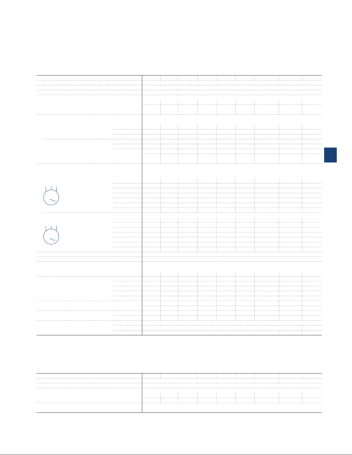
Main pole - Utilization characteristics according to IEC
Contactor types
Standards IEC 60947-1 / 60947-4-1 and EN 60947-1 / 60947-4-1
Rated operational voltage Ue max. 690 V 1000 V
Rated frequency (without derating) 50 / 60 Hz
Conventional free-air thermal current Ith
acc. to IEC 60947-4-1, open contactors, θ ≤ 40 °C
With conductor cross-sectional area 70 mm² 95 mm² 150 mm² 240 mm²
AC-1 Utilization category
For air temperature close to contactor
Ie / Rated operational current AC-1
Ue max. ≤ 690 V, 50/60 Hz
Ue max. ≤ 1000 V, 50/60 Hz
With conductor cross-sectional area 70 mm² 95 mm² 150 mm² 240 mm²
AC-3 Utilization category
For air temperature close to contactor θ ≤ 60°C (2)
Ie / Max. rated operational current AC-3 (1)
M
3-phase motors
3
Rated operational power AC-3 (1)
1500 r.p.m. 50Hz
M
1800 r.p.m. 60Hz
3
Rated making capacity AC-3 10 x Ie AC-3 acc. to IEC 60947-4-1
Rated breaking capacity AC-3 8 x Ie AC-3 acc. to IEC 60947-4-1
Short-circuit protection device for contactors
Without thermal overload relay - Motor protection excluded
Ue ≤ 500 V AC - gG type fuse 200 A 250 A 355 A 400 A 630 A 630 A 630 A 800 A 1000 A
Rated short-time withstand current Icw
At 40 °C ambient temperature,
in free air from a cold state
Maximum breaking capacity
cos φ = 0.45
Power dissipation per pole
Max. electrical switching frequency
(1) For the corresponding kW/A or hp/A values of 1500 r.p.m, 50 Hz or 1800 r.p.m, 60 Hz, 3-phase motors, see "Motor rated operational powers and currents".
(2) θ ≤ 55°C for EK550, EK1000
(3) For currents above 275 A use terminal enlargements or terminal extensions.
(4) For currents above 450 A use terminal enlargements or terminal extensions.
3-phase motors
AC / DC operated
θ ≤ 40 °C
θ ≤ 60 °C
θ ≤ 70 °C
θ ≤ 40 °C
θ ≤ 60 °C (2)
θ ≤ 70 °C
220-230-240V
380-400V
415V
440V
500V
690 V
1000V
220-230-240V
380-400V
415V
440V
500V
690 V
1000V
1 s
10 s
30 s
1 min
15 min
at 440 V
at 690 V
Ie / AC-1
Ie / AC-3
AC-1
AC-3
AC-2, AC4
AF116 AF140 AF190 AF205 AF265 AF305 AF370 EK550 EK1000
160 A 200 A 275 A 350 A 400 A 500 A 525 A 800 A 1000 A
(3)
160 A 200 A 275 A 350 A 400 A 500 A 525 A 800 A 1000 A
145 A 175 A 250 A 300 A 350 A 400 A 425 A 650 A 800 A
130 A 160 A 200 A 240 A 290 A 325 A 350 A 575 A 720 A
- - 250 A 275 A 350 A 375 A 400 A 800 A 1000 A
- - 225 A 250 A 300 A 325 A 350 A 650 A 800 A
- - 185 A 200 A 240 A 260 A 290 A 575 A 720 A
(3)
116 A 140 A 190 A 205 A 265 A 305 A 370 A 550 A 116 A 140 A 190 A 205 A 265 A 305 A 370 A 550 A 116 A 140 A 190 A 205 A 265 A 305 A 370 A 550 A 116 A 140 A 190 A 205 A 265 A 305 A 370 A 550 A -
- - - - - - - 550 A -
- - - - - - - 550 A -
- - - - - - - 175 A -
30 kW 37 kW 55 kW 55 kW 75 kW 90 kW 110 kW 160 kW 55 kW 75 kW 90 kW 110 kW 132 kW 160 kW 200 kW 280 kW 55 kW 75 kW 90 kW 110 kW 132 kW 160 kW 200 kW 315 kW 75 kW 90 kW 110 kW 132 kW 160 kW 160 kW 200 kW 315 kW -
- - - - - - - 400 kW -
- - - - - - - 500 kW -
- - - - - - - 250 kW -
1300 A 1460 A 1900 A 2050 A 2650 A 3050 A 3700 A 5500 A 6800 A
928 A 1168 A 1520 A 1640 A 2120 A 2440 A 2960 A 5300 A 6400 A
536 A 674 A 878 A 947 A 1224 A 1409 A 1709 A 3700 A 4400 A
379 A 477 A 621 A 670 A 865 A 996 A 1208 A 3000 A 3400 A
160 A 200 A 275 A 350 A 400 A 500 A 525 A 1000 A 1200 A
2000 A 3000 A 3300 A 3500 A 3800 A 4600 A 5000 A 5400 A -
- - - - - - - 5400 A 12 W 18 W 15 W 25 W 32 W 50 W 72 W 60 W 80 W
------- 25 W300 cycles/h
300 cycles/h -
- 120 cycles/h -
240 mm² 300 mm²
240 mm² 300 mm²
(4)
(4)
2x
185 mm² (4)
2x 185 mm²
(4)
2x
240 mm²
2x
240 mm²
2x
300 mm²
2x
300 mm²
5
Main pole - Utilization characteristics according to UL / CSA
Contactor types
Standards UL 60947-4-1 UL 508, CSA C22.2 N°14
Max. operational voltage 600 V
UL / CSA general use rating
600 V AC 160 A 175 A 230 A 250 A 300 A 350 A 420 A 540 A With conductor cross-sectional area AWG 2/0 AWG 3/0 MCM 250 MCM 250 MCM 400 MCM 500 2//MCM 300 - -
Max. electrical switching frequency
For general use 300 cycles/h
AC / DC operated
AF116 AF140 AF190 AF205 AF265 AF305 AF370 EK550 EK1000
ABB | 5/209
1SFC101209C0201 - Rev. B
Page 2
AF116 ... AF370 4-pole contactors
Technical data
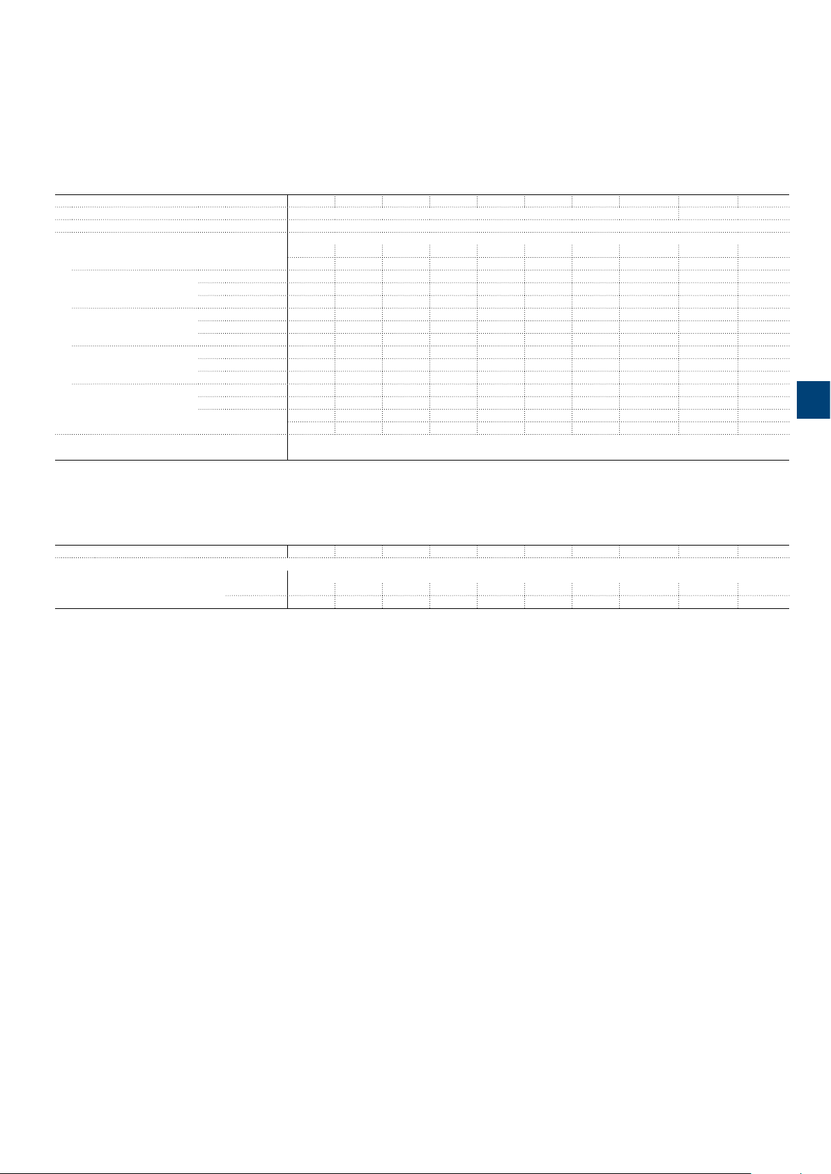
Main pole - Utilization characteristics according to UL/NEMA/CSA
Contactor types
Standards UL 60947-4-1 UL 508, CSA C22.2 N°14
Max. operational voltage 600 V
UL / CSA general use rating
600 V AC 160 A 175 A - 230 A 250 A 300 A 350 A 420 A 540 A With conductor cross-sectional area AWG 2/0 AWG 3/0 - MCM 250 MCM 250 MCM 400 MCM 500 2//MCM 300 - 1 pole
2 poles in serie
3 poles in serie
4 poles in series
With conductor cross-sectional area AWG 2/0 AWG 3/0 - MCM 250 MCM 250 MCM 400 MCM 500 2//MCM 300 - -
Max. electrical switching frequency
For general use 300 cycles/h
AC / DC operated
90 V DC
100 V DC
110 V DC
175 V DC
200 V DC
225 V DC
260 V DC
300 V DC
340 V DC
350 V DC
400 V DC
450 V DC
AF116 AF140 A F 14 6 AF19 0 AF205 AF265 AF305 AF370 EK550 EK1000
200 A 200 A - - - - - - - -
- - 250 A 350 A - - - - - -
- - - - 400 A 500 A 520 A - - 200 A 200 A - - - - - - - -
- - 250 A 350 A - - - - - -
- - - - 400 A 500 A 520 A - - 200 A 200 A - - - - - - - -
- - 250 A 350 A - - - - - -
- - - - 400 A 500 A 520 A - - 200 A 200 A - - - - - - - -
- - 250 A 350 A - - - - - -
- - - - 400 A 500 A 520 A - - -
5
Main pole utilization characteristics - 4 N.O. non-reversing contactors
Contactor types
Lighting application - UL/CSA - breaking all lines
Electrical discharge lamps (ballast)
1-phase per pole
3-phase break all lines
AC / DC operated
347 V AC
600 V AC
AF116 AF140 A F 14 6 AF19 0 AF205 AF265 AF305 AF370 EK550 EK1000
160 A 200 A 200 A 250 A 300 A 400 A 450 A 520 A - 160 A 200 A 200 A 250 A 300 A 400 A 450 A 520 A - -
ABB | 5/209
1SBC100067S0201
Page 3

AF116 ... EK1000 4-pole contactors
Technical data
General technical data
Contactor types
Rated insulation voltage Ui
acc. to IEC 60947-4-1 1000 V
acc. to UL / CSA 600 V
Rated impulse withstand voltage Uimp. 8 kV
Electromagnetic compatibility AF contactors comply with IEC 60947-1 / EN 60947-1 - Environment A
Ambient air temperature close to contactor
Operation -40 to +70 °C
Storage -40 to +70 °C
Maximum operating altitude (without derating) 3000 m
Mechanical durability
Number of operating cycles 5 million operating cycles
Maximum switching frequency 300 cycles/h
Shock withstand
acc. to IEC 60068-2-27 and EN 60068-2-27
Mounting position 1 No change in contact position, closed or open position
C1
ABB
A
B1
A
B2
C2
Vibration withstand
acc to IEC 60068-2-6 0.7 g closed position / 0.7 g open position 13.2…100 Hz
AC / DC operated
Shock direction
A
B1
B2
C1
C2
AF116 AF140 AF190 AF205 AF265 AF305 AF370
1/2 sinusoidal shock for 11 ms 1/2 sinusoidal shock for 30 ms
20 g 20 g
15 g closed position / 3 g open position 15 g closed position / 3 g open position
15 g closed position / 3 g open position 15 g closed position / 3 g open position
20 g 20 g
20 g 20 g
General technical data
Contactor types
Rated insulation voltage Ui
acc. to IEC 60947-4-1 1000 V
acc. to UL 600 V
Rated impulse withstand voltage Uimp. 8 kV
Electromagnetic compatibility EK contactors complying with IEC 60947-1 / EN 60947-1 - Environment A
Ambient air temperature close to contactor
Operation Fitted with thermal overload relay -25 to +55 °C -
Without thermal overload relay -40 to +70 °C -
Storage -50 to +70 °C -
Climatic withstand Category B acc. to IEC 60068-2-30
Maximum operating altitude (without derating) ≤ 3000 m
Mechanical durability
Number of operating cycles 5 millions operating cycles 3 millions operating cycles
Max. switching frequency 60 cycles/h
Shock withstand
acc. to IEC 60068-2-27 and EN 60068-2-27
Mounting position 1
Closed or open position
C1
ABB
AAB1
C2
AC or DC operated
Shock direction
B2
E1862D
EK550 EK1000
1/2 sinusoidal shock for 15 ms: no change in contact position, closed or open position
A
10 g
B1
10 g
B2
10 g
C1
10 g
C2
10 g
5
ABB | 5/211
1SFC 101212C0 201
Page 4

AF116 ... AF370 4-pole contactors
Technical data
Magnet system characteristics
Contactor types
Coil operating limits
acc. to IEC 60947-4-1
Rated control circuit voltage Uc 24...500 V AC, 20...500 V DC
Coil consumption
AC control voltage 50/60 Hz
24...60 V AC
48...130 V AC
100...250 V AC
250...500 V AC
DC control voltage
20...60 V DC
48...130 V DC
100...250 V DC
250...500 V DC
Drop-out voltage 55 % of Uc min
Operating time
Coil supply between A1 - A2
Between coil energization and:
Between coil de-energization and:
AC / DC operated
AC supply
DC supply
Average pull-in value
Average holding value
Average pull-in value
Average holding value
Average pull-in value
Average holding value
Average pull-in value
Average holding value
Average pull-in value
Average holding value
Average pull-in value
Average holding value
Average pull-in value
Average holding value
Average pull-in value
Average holding value
N.O. contact closing
N.O. contact opening
AF116 AF140 AF190 AF205 AF265 AF305 AF370
At θ ≤ 70°C 0.85 x Uc min ... 1.1 x Uc max
At θ ≤ 70°C 0.80 x Uc min ... 1.1 x Uc max
225 VA 165 VA 475 VA
5.5 VA 6 VA 8.5 VA
170 VA 175 VA 340 VA
4 VA 4 VA 17 VA
130 VA 220 VA 385 VA
6 VA 7 VA 17.5 VA
205 VA 185 VA 420 VA
16 VA 16 VA 21 VA
210 W 205 W 400 W
2.5 W 2.5 W 3.5 W
130 W 130 W 360 W
2.5 W 2.5 W 2.5 W
135 W 190 W 410 W
3 W 2.5 W 4.5 W
205 W 190 W 600 W
4 W 4 W 4.7 W
20...55 ms 25...60 ms 30...60 ms
40..70 ms 45...80 ms 45...80 ms
Mounting characteristics and conditions for use
Contactor types
Mounting positions
AC / DC operated
AF116 AF140 AF190 AF205 AF265 AF305 AF370
Pos
. 2
+30° -30°
5
Pos. 4
Max. add-on N.O. or N.C. auxiliary contacts: see accessory fitting details for 4-pole contactor
AF116 ... AF370
Mounting distances The contactors can be assembled side by side
Fixing
On rail acc. to IEC 60715, EN 60715 By screws (not supplied) 4 x M5
Pos. 3
Pos. 1 Pos. 1 ± 30°
Pos. 5
Pos. 6
1SFC101210 C0201
ABB | 5/213
Page 5

AF116 ... AF370 4-pole contactors
Technical data
Connecting characteristics
Contactor types
Main terminals
Flat type
Connection capacity (min. ... max.)
Main conductors (poles)
Cu cable - Stranded
Clamp type LD... included (1) 1SDA066917R1 1SDA055016R1
Tightening torque 8 Nm 14 Nm 25 Nm
Cu cable - Stranded
Clamp type LD... included (1) 1SFN074709R1000,
Tightening torque 8 Nm 16 Nm 22 Nm
5
Al cable - Stranded
Clamp type – 1SDA054988R1 1SDA055020R1
Tightening torque – 31 Nm 43 Nm
Cu cable - Flexible
Clamp type LD... included (1) 1SDA066917R1 1SDA055016R1
Tightening torque 8 Nm 14 Nm 25 Nm
Cu cable - Flexible
Clamp type LD... included (1) 1SFN074709R1000,
Tightening torque 8 Nm 16 Nm 22 Nm
Lugs
ø
L
Socket type LL... included LL... included LL... included
Tightening torque 9 Nm / 80 lb.in 18 Nm / 160 lb.in 28 Nm / 248 lb.in
Connection capacity acc. to UL / CSA
Clamp type LD... included (1) ATK185 (2) ATK300 (2)
Tightening torque 8 Nm / 71 lb.in 34 Nm / 301 lb.in 42 Nm / 372 lb.in
Connection capacity acc. to UL / CSA
Clamp type LD... included (1) – ATK300/2 (2)
Tightening torque 8 Nm / 71 lb.in – 42 Nm / 372 lb.in
Auxiliary conductors
(coil terminals)
Solid / stranded
Flexible
Flexible with non insulated ferrule
Flexible with insulated ferrule
Lugs
L
l
Connection capacity acc. to UL / CSA
Stripping length 9 mm
Tightening torque 1.00 Nm / 9 lb.in
Degree of protection
acc. to IEC 60947-1 / EN 60947-1 and IEC 60529 / EN 60529
Main terminals IP00
Coil terminals IP20
Screw terminals
Main terminals M6 M8 M10
Coil terminals (delivered in open position) M3.5
(1) LD... not included for AF116 ... AF146-30-..B.
(2) Available in North America only.
AC / DC operated
1 x
2 x
1 x
1 x
2 x
W ≤
Ø >
1 x
2 x
1 x
2 x
1 x
2 x
1 x
2 x
1 x
2 x
L <
l >
1 or 2 x
Screwdriver type
Screwdriver type
AF116 AF140 AF190 AF205 AF265 AF305 AF370
13
ø 6.5
3
7
5
ø 8.5
10...95 mm² 6...150 mm² 16...300 mm²
10...95 mm² 50...120 mm² 70...185 mm²
LZ185-2C/120
– 95...185 mm² 185...240 mm²
10...70 mm² 6...120 mm² 16...240 mm²
10...70 mm² 50...95 mm² 70...185 mm²
LZ185-2C/120
22 mm (.866 in) 24 mm (.945 in) 32 mm (1.260 in)
6 mm (.236 in) 8 mm (.315 in) 10 mm (.394 in)
AWG 6…3/0 6…300 MCM 4…400 MCM
AWG 6…3/0 – 4…500 MCM
1...4 mm²
1...4 mm²
0.75...2.5 mm²
0.75...2.5 mm²
0.75...2.5 mm²
0.75...2.5 mm²
0.75...2.5 mm²
0.75...2.5 mm²
8 mm
3.5 mm
AWG 18...14
Screws and bolts
Flat Ø 5.5 mm / Pozidriv 2
17.5
10
5
ø 10.5
1SCA022194R0890,
OZXB4
1SCA022194R0890,
OZXB4
19.5
14.3
5/216 | ABB
1SFC 101213C02 01
 Loading...