

Page 1
Data sheet
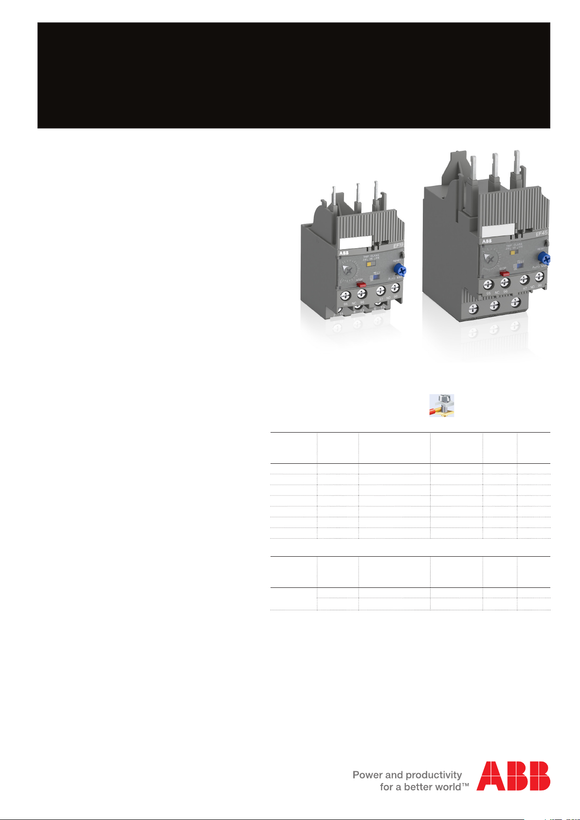
Electronic overload relay EF19 and EF45
Electronic overload relays offer reliable
protection in case of overload and
phase-failure. They are the alternative to
thermal overload relays. Motor starters
are combinations of overload relays and
contactors.
2CDC231011V0013
2CDC231010V0013
Description
– Overload protection – trip class 10E, 20E, 30E
selectable
– Phase loss sensitivity
– Temperature compensation from -25 … +70 °C
– Adjustable current setting for overload protection
– Automatic or manual reset selectable
– Trip-free mechanism
– Status indication
– STOP and TEST function
– Direct mounting onto block contactors
– Sealable operating elements
– Self-supplied devices
Order data
EF19, EF45 screw terminal
For AF09 … AF38 block contactors
Setting
range
A
0.10 ... 0.32 EF19-0.32 1SAX121001R1101 AF09 ... AF38 1 0.158
0.30 ... 1.00 EF19-1.0 1SAX121001R1102 AF09 ... AF38 1 0.158
0.80 ... 2.70 EF19-2.7 1SAX121001R1103 AF09 ... AF38 1 0.158
1.90 ... 6.30 EF19-6.3 1SAX121001R1104 AF09 ... AF38 1 0.158
5.70 ... 18.9 EF19-18.9 1SAX121001R1105 AF09 ... AF38 1 0.158
9.00 ... 30.0 EF45-30 1SAX221001R1101 AF26 ... AF38 1 0.362
15.0 ... 45.0 EF45-45 1SAX221001R1102 AF26 ... AF38 1 0.362
Type Order code Suitable for Packing
unit
PCE
Weight
per PCE
kg
Accessories
Single
mounting kit
Type Order code Suitable for Packing
unit
PCE
DB19EF 1SAX101910R1001 EF19 1 0.046
DB45EF 1SAX201910R0001 EF45 1 0.100
Weight
per PCE
kg
Suitable for mounting on:
AF09, AF12, AF16
AF26, AF30, AF38
Page 2
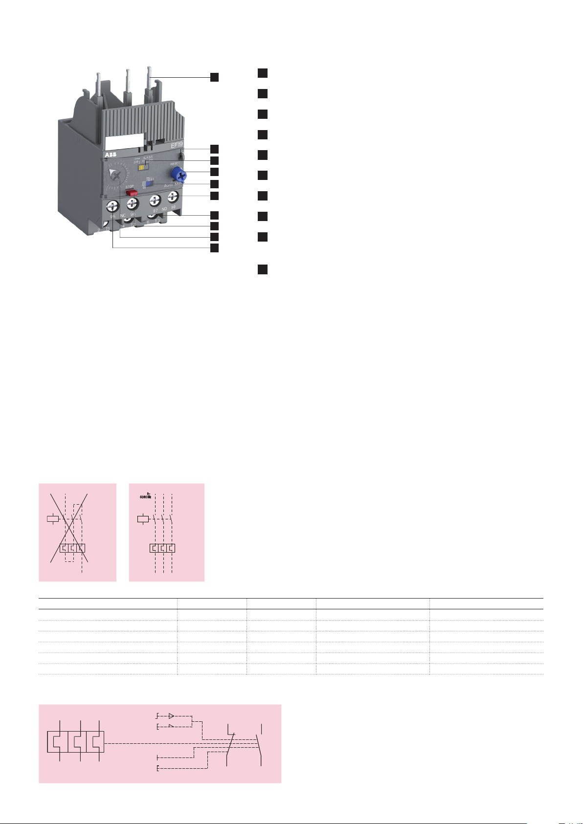
Functional description
1
Terminals 1L1, 3L2, 5L3
2
Sealable operating elements
3
Trip class 10E, 20E, 30E selectable
4
RESET - Automatic or manual reset selectable
5
TEST - Status indication
6
Signaling contacts 97-98
7
Terminals 2T1, 4T2, 6T3
8
STOP
9
Current setting range / Self-test function ST
Adjustable current setting for overload protection
10
Tripping contacts 95-96
2CDC232013F0013
1
2
3
4
5
6
7
8
9
10
Application / internal function
The self-supplied electronic overload relays are three pole electronic/mechanical devices. The motor current flows through
build-in current transformers and an evaluation circuit will recognize an overload (over current). This will lead to a release
of the relay and a change of the contacts switching position (95-96 / 97-98). The contact 95-96 is used to control the load
contactor. The electronic overload relay is self-supplied, which mean no extra external supply is needed.
The overload relays have a setting scale in Amperes, which allows the direct adjusting of the relay without any additional
calculation. In compliance with international and national standards, the setting current is the rated current of the motor and
not the tripping current (no tripping at 1.05 x I, tripping at 1.2 x I; I = setting current). The relays are constructed in a way
that they protect themselves in the event of an overload. The overload relay has to be protected against short-circuit. The
appropriate short-circuit protective devices are shown in the following tables.
To prevent thermal overloads in heavy duty applications, the correct cable sizes have to be selected.
Operation mode
1~
2CDC232013F0012
Trip state open closed
RESET state closed open ON
TEST manual reset mode open closed
TEST auto reset mode open closed
STOP while device is in trip state open closed STOP button has no function
STOP while device is in RESET state open open while STOP button is pressed
50/60 Hz
3~
2CDC232005F0013
Contact 95-96 Contact 97-98 Opto-mechanical slide Comment
Wiring diagram
2T1 4T2 6T3
RESET
A
M
TEST
STOP
9795
9896
2CDC232001F0009
2 - 2CDC107025D0201
Page 3
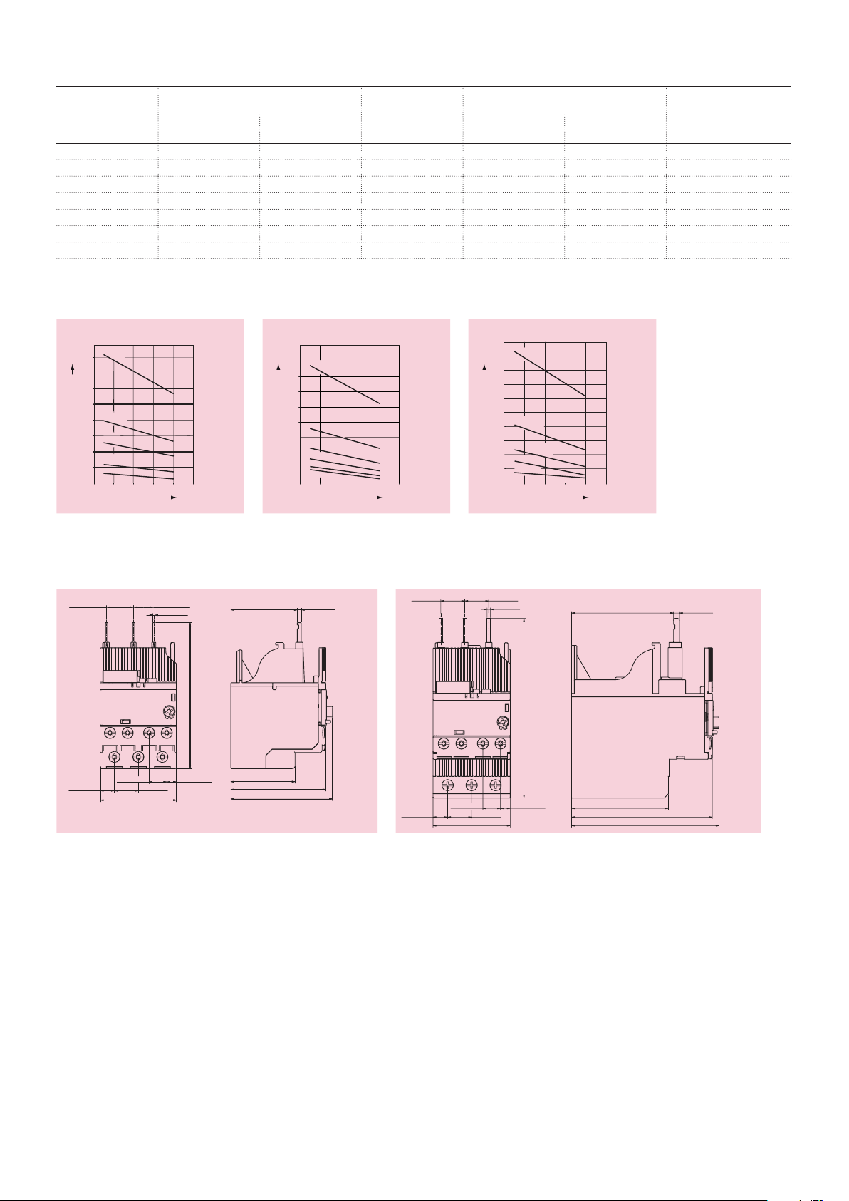
Resistance and power loss per pole and short-circuit protective devices
switching frequency
Trip class 10E
Trip class 20E
switching frequency
Trip class 30E
14
0.55"
14
0.55"
Type Setting range Resistance per
pole
lower value
A
upper value
A
mΩ
EF19-0.32 0.1 0.32 447
EF19-1.0 0.3 1 54
EF19-2.7 0.8 2.7 7.9
EF19-6.3 1.9 6.3 2.1
EF19-18.9 5.7 18.9 0.85
EF45-30 9 30 0.26
EF45-45 15 45 0.26
Intermittent periodic duty
(Op/h)
t = 0.5 s
a
160
140
120
100
t = 1 s
a
80
60
t = 1.5 s
a
40
t = 3 s
a
20
t = 5 s
a
0
0 20 40 60 80 100
duty ratio
(%)
(Op/h)
80
t = 2 s
a
70
60
50
40
t = 4 s
a
30
switching frequency
20
10
2CDC232001F0214
t = 6 s
a
t = 8 s
a
t = 10 s
a
t = 12 s
a
0
0 20 40 60 80 100
duty ratio
(%)
Power loss per pole Short-circuit
protective devices
at lower value Wat upper value Wcoordination type 2
0.004 0.046
0.005 0.054
0.005 0.058
0.008 0.083
0.028 0.304
0.021 0.234
0.059 0.527
(Op/h)
50
t = 5 s
a
45
40
35
30
25
t = 10 s
a
20
15
t = 15 s
a
10
t = 20 s
a
t = 25 s
a
5
0
0 20 40 60 80 100
2CDC232002F0214
duty ratio
(%)
Fuse 1 A, Type gG
Fuse 4 A, Type gG
Fuse 10 A, Type gG
Fuse 20 A, Type gG
Fuse 50 A, Type gG
Fuse 160 A, Type gG
Fuse 160 A, Type gG
2CDC232003F0214
Trip class 10E Trip class 20E Trip class 30E
Dimensions
15.73
0.62"
8.2
0.32"
EF19 EF45
10.3
44.4 1.75"
0.41"
11.78
0.46"
1.2 0.05"
85 3.35"
5.65
14
0.55"
0.22"
38.8
1.53"
37.5 1.48"
55.4 2.18"
29.3 2.33"
2.3
0.09"
0.33"
10.3
8.5
2CDC232007F0009
0.41"
45 1.77"
2 0.08"
104.7 4.12"
5.65
14
0.55"
0.22"
59.5
56.5 2.22"
2.34"
82.1 3.23"
86 3.39"
3.4
0.13"
2CDC232008F0009
2CDC107025D0201 - 3
Page 4

14.8
39.1
67.1
0.58"
1.54"
4.75
121.7
98.5
0.2"
4.8"
3.9"
120.2
4.7"
4.3
0.17"
14 14
0.55" 0.55"
44.4
1.75"
3.63"
92.1
1.78"
45.1
2.64"
3.61"
4.07"
91.7
1.97"
103.5
50
5.5
0.22"
69.7
2.74"
70.8
2.79"
3.39"
86.2
4.7
0.19"
35
2CDC232001F0013
1.38"
DB19EF + EF19 DB19EF drilling plan
3.6"
92.6
0.2"
1.4"
35.5
3
0.1"
4.5
29.6
1.2"
5.2"
4.2
0.2"
131.2
0.2"
5.5
1.3"
32.5
0.2"
111.25
4.75
2CDC232002F0013
2.2"
2"
56.75
0.1"
3
4.5
0.2"
1.4"
35
1.8"
45
50.75
5.5
0.2"
10.5
0.4"
3.8"
95.4
3.8"
96.5
0.5" 4.4"
12.45
5
0.2"
35
2CDC232005F0014
1.4"
DB45EF + EF45 DB45EF drilling plan
2CDC232006F0014
4 - 2CDC107025D0201
Page 5

Technical data IEC/EN
Data at T
= 40 °C and at rated values, if nothing else indicated
A
Main circuit
2T1-4T2-6T3
Rated operational voltage U
e
Setting range - electronic overload protection see table on page 1
Rated operational current AC-3 I
e
Trip class 10E, 20E, 30E, selectable
Rated frequency 50/60 Hz
Number of poles 3
Resistance per pole see table on page 3
Power loss per pole see table on page 3
Short-circuit protective devices see table on page 3
Isolation data 2T1-4T2-6T3
Rated impulse withstand voltage U
Rated insulation voltage U
imp
i
Pollution degree 3
Overvoltage category up to III
Electrical connection EF19 EF45 DB19EF DB45EF
Connecting capacity solid 1/2 x 1 ... 4 mm² 1/2 x 2.5 ... 16 mm² 1 x 1 ... 4 mm² 1/2 x 2.5 ... 16 mm²
stranded 1/2 x 1 ... 4 mm² 1/2 x 2.5 ... 16 mm² 1 x 1 ... 4 mm² 1/2 x 2.5 ... 16 mm²
flexible with ferrule 1/2 x 0.75 ... 2.5 mm² 1/2 x 2.5 ... 10 mm² 1 x 0.75 ... 2.5 mm² 1/2 x 2.5 ... 10 mm²
flexible with ferrule insulated 1/2 x 0.75 ... 2.5 mm² 1/2 x 2.5 ... 10 mm² 1 x 0.75 ... 2.5 mm² 1/2 x 2.5 ... 10 mm²
flexible without ferrule 1/2 x 0.75 ... 2.5 mm² 1/2 x 2.5 ... 10 mm² 1 x 0.75 ... 2.5 mm² 1/2 x 2.5 ... 10 mm²
Stripping length 9 mm 13 mm 12 mm 15 mm
Tightening torque 0.8 ... 1.5 Nm 2.3 … 2.6 Nm 0.8 ... 1.5 Nm 0.8 ... 1.5 Nm
Recommended screw driver Pozidriv 2 Pozidriv 2 Pozidriv 2 Pozidriv 2
690 V AC
- V DC
see upper value of setting range, table on page 3
6 kV
690 V
2CDC107025D0201 - 5
Page 6

Auxiliary circuit
95-96, 97-98
Rated operational voltage U
Conventional free air thermal current I
e
th
Rated frequency DC, 50/60 Hz
Number of poles 1NC + 1NO
Rated operational current I
e
acc. to IEC/EN 60947-5-1 for utilization category
at AC-15 at 110-120 V NC, 95-96 3.00 A
NO, 97-98 3.00 A
at AC-15 at 220-230-240 V NC, 95-96 3.00 A
NO, 97-98 3.00 A
at AC-15 at 440 V NC, 95-96 1.10 A
NO, 97-98 1.10 A
at AC-15 at 480-500 V NC, 95-96 0.75 A
NO, 97-98 0.75 A
at DC-13 at 24 V NC, 95-96 1.50 A
NO, 97-98 1.50 A
at DC-13 at 110-120-125 V NC, 95-96 0.55 A
NO, 97-98 0.55 A
at DC-13 at 250 V NC, 95-96 0.27 A
NO, 97-98 0.27 A
at DC-13 at 500 V NC, 95-96 0.10 A
NO, 97-98 0.10 A
Minimum switching capacity 12 V / 3 mA
Short-circuit protective devices fuse 6 A, Type gG
600 V
6 A
-7
; Ukd = 3 V / 500.000 operating cycles
l = 10
Isolation data 95-96, 97-98
Rated impulse withstand voltage U
Rated insulation voltage U
i
imp
6 kV
690 V
Pollution degree 3
Overvoltage category up to III
Electrical connection 95-96, 97-98
Connecting capacity solid 1/2 x 1 ... 4 mm²
stranded 1/2 x 1 ... 4 mm²
flexible with ferrule 1/2 x 0.75 ... 2.5 mm²
flexible with ferrule insulated 1/2 x 0.75 ... 2.5 mm²
flexible without ferrule 1/2 x 0.75 ... 2.5 mm²
Stripping length 9 mm
Tightening torque 0.8 ... 1.2 Nm
Recommended screw driver Pozidriv 2
6 - 2CDC107025D0201
Page 7

General data
Duty time 100 %
Operating frequency without early tripping up to 15 operations/h or 60 operations/h with
40 % duty ratio, if the motor breaking current 6 x In
and the motor starting time does not exceed 1 s
Dimensions (W x H x D) see dimension drawing
Weight see ordering data
Mounting mount on the contactor and tighten the screws of
the main circuit terminals or with single mounting kit
on DIN rail (35 mm)
Mounting position optional, position 1-6
Minimum distance to other units same type horizontal none
vertical not applicable
Minimum distance to electrical conductive board horizontal 1.5 mm
vertical 1.5 mm
Degree of protection Housing / main circuit terminals IP20 (depends on contactor)
Maximum operating altitude up to 2000 m
Electromagnetic compatibility
Immunity acc. to IEC 60947-1 Environment A
Emission acc. to IEC 60947-1 Environment B
Environmental data
Ambient air temperature
Operation
Storage -50 ... +85 °C
Ambient air temperature compensation acc. to IEC/EN 60947-4-1
Resistance to vibrations acc. to IEC 60068-2-6 3g / 3 ... 150 Hz
Resistance to shock acc. to IEC 60068-2-27 25g / 11 ms
open - compensated
open
-25 ... +70 °C
-25 ... +70 °C
Standards / directives
Standards IEC/EN 60947-1
IEC/EN 60947-4-1
IEC/EN 60947-5-1
UL 60947-1
UL 60947-4-1
Low Voltage Directive 2006/95/EC
EMC Directive 2004/108/EC
RoHS Directive 2002/95/EC
2CDC107025D0201 - 7
Page 8

Technical data UL/CSA
Full load amps and short-circuit protective devices
Type Full load
amps
(FLA)
EF19-0.32
EF19-1.0
EF19-2.7
EF19-6.3
EF19-18.9
EF45-30
EF45-45
1)
@ 600 V AC
0.32 A
1.00 A
2.70 A
6.30 A
18.9 A
30.0 A
45.0 A
Short circuit protective devices
480 V AC 480 V AC 600 V AC 600 V AC 600 V AC
SCCR Fuse K5
/ RK5
50 kA 2 A -
SCCR Circuit
breaker
65 kA 15 A 5 kA 2 A 100 kA 2 A - -
Class J
Fuse
50 kA 2 A 65 kA 15 A 5 kA 2 A 100 kA 2 A - -
50 kA 4 A 65 kA 15 A 5 kA 4 A 100 kA 4 A - -
50 kA 15 A 65 kA 35 A 5 kA 15 A 100 kA 15 A - -
50 kA 30 A 65 kA 35 A 5 kA 30 A 100 kA 30 A 10 kA 20 A
18 kA
18 kA
1)
1)
150 A
250 A
1)
65 kA 70 A 5 kA 150 A 100 kA 150 A -
1)
65 kA 70 A 5 kA 250 A 100 kA 200 A -
Main circuit
Maximum operational voltage 600 V AC
Trip rating 125 % of FLA
Full load amps (FLA) see table above
Short-circuit rating RMS symmetrical see table above
Short-circuit protective devices see table above
SCCR Fuse K5
/ RK5
SCCR Fuse J SCCR Circuit
breaker
-
-
Electrical connection EF19 EF45 DB19EF DB45EF
Connecting capacity stranded 1/2 x AWG 16 ... 10 1/2 x AWG 14 ... 6 1/2 x AWG 16 ... 10 1/2 x AWG 18 ... 10
flexible without ferrule 1/2 x AWG 16 ... 10 1/2 x AWG 14 ... 6 1/2 x AWG 16 ... 10 1/2 x AWG 18 ... 10
Stripping length 9 mm 13 mm 12 mm 15 mm
Tightening torque 7 ... 13 Ib-in 20 ... 22 Ib-in 7 ... 13 Ib-in 7 ... 13 Ib-in
Recommended screw driver Pozidriv 2 / M3.5 Pozidriv 2 / M5 Pozidriv 2 / M3 Pozidriv 2 / M3
Auxiliary circuit
Conventional thermal current 5 A
Making and breaking capacity NC / NO B600, Q600
Electrical connection
Connecting capacity stranded 1/2 x AWG 18 ... 10
flexible without ferrule 1/2 x AWG 18 ... 10
Stripping length 9 mm
Tightening torque 7 ... 11 Ib-in
Recommended screw driver Pozidriv 2
8 - 2CDC107025D0201
 Loading...