

Page 1
Type DTW
De-energized Tap Changer
Application, Installation &
Selection Guide
IL 44-751-1
Instruction Leaflet
Page 1 November,2001
Page 2

IL 44-751-1
Instruction Leaflet
Page 2 November, 2001
Scope
This guide contains general information for ordering and installing the type DTW de-energized tap
changer. This guide does not describe all possible contingencies, which may arise during
installation, operation, or maintenance of the tap changer, nor does it describe all details and
variations of the equipment. If you require additional information regarding the installation and
the operation or maintenance of your equipment, contact the local representative of ABB.
Safety Definitions
Safety notations are intended to alert personnel of possible conditions, which may cause personal
injury, property damage, or even death. They have been inserted into this instructional text prior
to the step in which the condition is cited.
The safety notations are headed by one of three hazard intensity levels, which are defined as
follows:
1. DANGER- immediate hazard that will result in severe personal injury, property damage, or
death.
2. WARNING- hazard or unsafe practice that could result in personal injury, property damage,
or death.
3. CAUTION- hazard or unsafe practice, which could result in minor personal injury, or property
damage.
Introduction
The type DTW de-energized tap changer is one of a family of ABB tap changers for power
transformers. A de-energized tap changer is a switch, which is connected to the winding taps of
the transformer. When the tap changer is moved from one position to another, the amount of the
tap winding connected into the circuit is changed. This permits the adjustment of the voltage ratio
of the transformer to best suit the voltage requirements at the transformer’s installation site. The
de-energized tap changer is usually installed into the high voltage circuit of the transformer and,
most of the time, it is used to adjust the primary voltage of the transformer within a 10 percent
range in 5 steps.
D A N G E R
The type DTW tap changer is a de-energized tap changer, and must, be operated only
when the transformer is completely de-energized. This type of tap changer must never be
operated when the transformer is energized. Operation when the transformer is energized
is dangerous and will result in severe personal injury, property damage, or death.
The type DTW tap changer is a modular, bridging-type (zigzag) tap changer with external
operating mechanism. It is most commonly available as a 5-position device. Other
configurations are available or can be designed; for these, please contact ABB. The type DTW
tap changer is made up of individual tap decks (one or two per phase). The phase tap decks are
connected to a common set of horizontal operating shafts through individual gear sets. The tap
changer is mounted in front of each phase coil, parallel to the side of the transformer tank. The
tap changer is supported by an insulating framework, which is part of and attached to the
transformer superstructure. See Figure 1 for a general view of a type DTW tap changer
installation.
The ability to locate the type DTW tap changer on the side of each phase coil permits very direct
tap lead routing with a minimum of bends.
Page 3
IL 44-751-1
Instruction Leaflet
Page 3 November, 2001
Figure 1: Typical installation of the type DTW tap changer
All materials used in the construction of the type DTW tap changer have been chosen for their
superior electrical properties, mechanical strength, temperature extremes capability, corrosion
resistance, transformer oil compatibility, and light weight.
Page 4
IL 44-751-1
Instruction Leaflet
Page 4 November, 2001
Ratings
The type DTW tap changer is available in one basic current rating and is offered with several
different electrostatic shielding and insulation options. Table 1 presents the various rating options.
Table 1. DTW Ratings
Test/ Parameter Rated Value Ref. Dimension
on Tap Changer
Voltage Class
Phase to ground and phase to phase:
Lightning Impulse
60 Hz. Power Frequency
Between Adjacent contacts:
Lightning Impulse
60 Hz. Power Frequency
Short circuit current
Rated Current
1
See Figure 2
2
Based on a steady state contact temperature rise of 15°C at a continuous current equal to 120%
of rated current.
3
The dielectric withstand from tap deck to ground and from phase to phase is very much
2
dependent on the electrical clearance distances which are maintained by the transformer design.
See also Electrostatic Shielding and Insulation (page 9).
See note 3 N/A
See note 3 N/A
220 kV
70 kV
(A-B, B-C, C-D,
D-E, E-F, F-A)
10,000 A r.m.s. N/A
850 A N/A
1
Figure 2.
Page 5
IL 44-751-1
Instruction Leaflet
Page 5 November, 2001
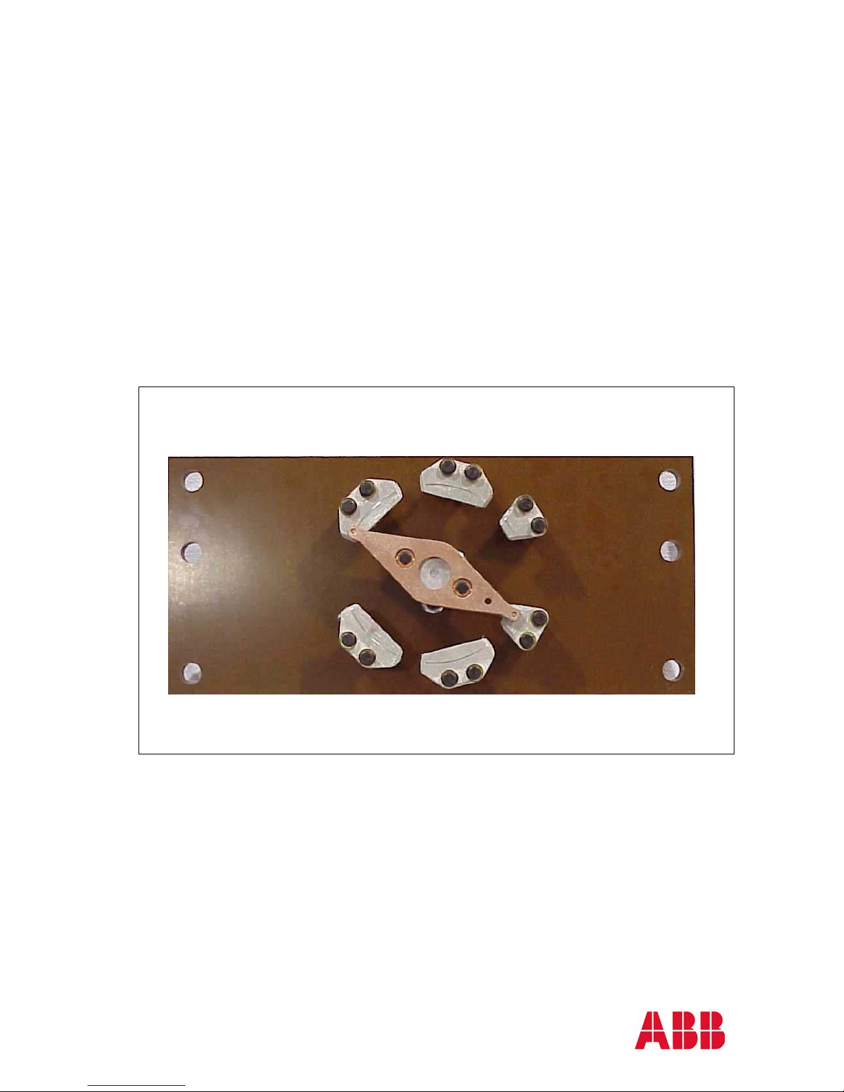
Construction Details and Features
Basic Information
The DTW, de-energized tap changer, is constructed from six major components: 1) Tap deck, 2)
Worm gear set, 3) Moving contacts, 4) Stationary contacts, 5) Mounting post and 6) Drive shaft
and External operating mechanism. These individual components (except number 6) are shown
in Figure 3 and Figure 4.
Copper Mounting
5
Post
Stationary
4
Contact
Silver/Copper
Contact Button
Moving Contact
3
Assembly
1
Tap Deck
Plate
Contact Drive
Shaft
Figure 3: Contact structure
Figure 4: Worm gear set, 2), and ball end fittings
Page 6

IL 44-751-1
Instruction Leaflet
Page 6 November, 2001
Tap Deck
The tap deck is a flat insulating plate. This plate serves as the base to which all of the other tap
changer components are bolted. The main deck contains six through holes, which are used to
bolt the tap changer to the transformer framework. The flat insulating plate is machined from high
strength, electrical grade, low power factor Micarta. This structure carries all of the mechanical
loads created by the weight of the tap leads and the thrust and weight of the drive shafts.
Worm Gear Set
This gear set is mounted on the main deck’s outboard face. Its function is to convert the rotary
action of the driving shaft 90 degrees in order to turn the moving contacts from position to
position. This gear set is contained within a cast metal housing. The function of the housing is to
position and hold the gear set and to provide a smooth, rounded corner enclosure in order to
minimize electrical stress concentration. The nature of the gearing is such that one full turn of the
drive shaft rotates the moving contacts from one set of stationary contacts to the next.
Contacts
The stationary contacts are machined from copper flat stock and are 0.25 inches (6.4 mm) thick.
The leading edges are chamfered to permit the moving contacts to easily slide up into position.
These contacts are tin-plated. The stationary contacts are bolted to copper mounting posts,
which in turn, are bolted to the phase deck. Two bolts are used for each contact. The bolt heads
and nuts are shielded with special, toriodially-shaped, washers to minimized electrical stress
concentration.
The copper mounting posts serve as the connection point for the tap leads. The tap leads from
the coil should be terminated with a two-hole flat connector. The flat connector is bolted to the
mounting post with two 0.375 (9.5 mm) bolt sets. The mounting posts “capture” the bolt head so
that only the nut has to be turned to tighten the joint.
The moving contact set is a “pincer” type of contact; the spring loaded contact plates slide over
the stationary contacts. See Figure 5. Each contact plate is made from copper flat stock. The
copper plates are tipped with semi-spherical, silver-copper alloy contact buttons. This alloy
contact button assures a positive, low friction, low resistance current path at all times, even when
taps are changed very infrequently. The sliding action of the contact button over the chamfered
stationary contact plate creates a good wiping action during the tap change which further
guarantees a solid, low resistance electrical contact. Contact pressure is precisely controlled by
two coil springs, which are set and calibrated at the factory to provide uniform and consistent
contact pressure. The combination of contoured interface surfaces between the moving and
stationary contacts and the accurately calibrated spring loaded pincer contacts minimizes the
force needed to drive the tap changer from one position to another. The pincer type of contact
takes advantage of the magnetic attractive forces created during through faults or current surges.
These additional compression forces yield high fault current withstand capability by preventing
contact bounce and arcing during faults. These features permit the tap changer to have a
relatively low driving torque and, yet maintain a high through fault current withstand capability.
Page 7

IL 44-751-1
Instruction Leaflet
Page 7 November, 2001
Figure 5. Moving contact
Driving System
The drive system consists of several parts: 1) the worm gear drive, 2) the inter-phase shafts, 3)
the main drive shaft and 4) the external operating mechanism. See Figure 6.
The moving contact’s steel shaft is fixed to the worm gear assembly. The gear is meshed with
the worm driver, which is attached to the drive shaft through ball joints. The entire worm driver
assembly is designed to provide positive drive shaft engagement with a minimum of backlash and
maximum forgiveness of shaft misalignment. The worm driver terminates in a ball-shaped, shaft
end.
The inter-phase shafts are non-metallic Micarta tubes. These shafts slide over the ball-ends of
the worm drive shaft creating a ball and socket type of joint. The ends of each inter-phase shaft
have slip joints to make assembly easy and also to allow for some minor miss-alignment and to
accommodate movement due to thermal expansion of the transformer.
The main drive shaft connects the operating mechanism to the first tap changer deck. This shaft
is also a non-metallic Micarta tube. A telescoping connecting tube connects the main drive shaft
to the external operating mechanism
The combination of ball joint connectors, telescoping and slip joint shaft tubes allows the drive
mechanism to accommodate misalignments between tap changer decks or the operating
mechanism and permits the shaft and drive mechanism to adjust to dimensional changes that
occur as the transformer responds to temperature variations.
The shaft seal of the external operating mechanism consists of a packing gland backed up by a
secondary O-ring to form a redundant shaft seal between the operating shaft and the
atmosphere. The operating mechanism is sealed to the mounting boss by a flat gasket, which is
retained by a machined groove in the flange of the mounting boss. The operating mechanism is
bolted to the mounting boss.
The external operating mechanism drives the tap changer’s operating shaft such that one
complete revolution of the external handle indexes each tap deck one position. This one-turnper-tap action allows the driving mechanism system to absorb any backlash in the entire tap
changer structure and still provide precise positioning of the tap changer contacts.
To make a tap change, the operator must perform two separate actions: 1) pull the fixing pin
which frees the mechanism shaft and 2) turn the operating handle 360 degrees. The position
number is indicated by a number on a Geneva dial and is visible through the view port. A position
number is only fully visible when the tap changer is in position. The fixing pin will not re-seat itself
Page 8

IL 44-751-1
Instruction Leaflet
Page 8 November, 2001
unless the tap changer is fixed on a position. Positive mechanical stops are built into the tap
changing mechanism, which will prevent turning past the lowest and highest positions.
The external mechanism can be pad locked in any position (pad lock not supplied by ABB).
Figure 7 shows the location of the pad-lock.
All external parts are made of non-corrosive materials.
Mounting Boss (welded to tank)
External Operating Mechanism
4
2
Inter-Phase
Shaft
Tap Changer Deck
Ball End
Fitting
Ball End Fitting
1
Worm Gear
Assembly
Drive Shaft
Sliding Fit
Connection
3
Figure 6: Drive System (mounting boss not supplied by ABB Alamo)
Figure 7: Location of pad-lock on external mechanism. (Pad-lock not supplied by ABB Alamo)
Page 9

IL 44-751-1
Instruction Leaflet
Page 9 November, 2001
Electrostatic Shielding and Insulation
Electrical spacing requirements between the tap decks and the tank wall and between the tap
decks and adjacent phases or other metallic objects is a complex subject. When designing the
transformer, required electrical clearance distances should be calculated between phase decks
and between phase decks and ground or other parts of the transformer. Three levels of shielding
and insulation are available for the tap decks.
1. Unshielded: Tap decks do not have any electrostatic shields. This configuration is typically
used for applications, which have a impulse voltage withstand requirement of 200 kV or less.
See Figure 8.
2. Level 1 Electrostatic Shielding: A cast-aluminum electrostatic shield ring is placed between
the tap changer deck and the transformer tank wall. This ring is referred to as the “outer
shield”. The ring is bolted to an aluminum mounting plate, which is, in turn, bolted to the
worm gear housing. The ring portion of each shield is insulated with a layer of crepe paper
wrap. This configuration is, typically, used for applications, which require a impulse voltage
withstand of 650 kV or less. See Figure 9.
3. Level 2 Electrostatic Shielding: Cast-aluminum, electrostatic shield rings are mounted on both
the tank wall side and the coil side of each tap deck. Both the inner and outer shield rings
are bolted to the shield mounting plate, which was described above. The outer ring portion of
each shield is a continuous ring. The inner shield consists of two half-circle rings. See
Figure 10. In addition to the aluminum rings, a pressboard disk is placed in front of the
aluminum mounting plate and a pressboard box shield is added to the tank wall side of each
tap deck. This box shield is attached to the transformer support structure with cotton tape.
The pressboard disk is attached to the aluminum mounting plate with cotton tape. This
configuration is, typically, used for applications which require a impulse voltage withstand
greater than 650 kV; the upper limit of impulse withstand in this configuration is determined
by the electrical clearances designed into the transformer.
Figure 8. DTW without any shielding. Figure 9. DTW with shield on tank side.
shielding. NOTE: only one of the inner shields
Figure 10. DTW with both inner and outer
are assembled in this figure.
Page 10

IL 44-751-1
Instruction Leaflet
Page 10 November, 2001
Standard Configurations
The type DTW tap changer is built in three standard configurations based on mounting the tap
decks along the side of each phase coil. The operating mechanism may be ordered for mounting
on either the left or the right hand side of the tap decks (when viewed from outside of the
transformer). An ordering data sheet is provided to permit the customer to specify configuration,
mechanism location, critical spacing dimensions and electrostatic shielding requirements. This
information is necessary before a complete order can be entered for a tap changer.
♦ Configuration A: One tap deck per phase coil, (three tap decks in total). The operating
mechanism and shafts are aligned horizontally with the tap deck. The external operating
mechanism is located at the approximate vertical center of the tap deck. See Figure 11. An
optional, external gear box and mechanism set is available which permits the external
operating mechanism to be located at ground level. This is called Configuration C
♦ Configuration B: Two tap decks per phase coil, (six tap decks in total). In this configuration,
two sets of operating shafts are brought to the outside of the transformer in two gearboxes.
The mechanical connection between the two sets of deck drive shafts being made through
appropriate gearing and shafting within and between the two gearboxes. See Figure 12.
♦ Configuration C: Same as configuration A except the bevel gear set and operating
mechanism of Configuration B are used to lower the height of the operating mechanism. This
configuration is used when the operating mechanism must be located close to ground level.
See Figure 13.
Figure 11. Configuration A Figure 12. Configuration B
Figure 13. Configuration C
NOTE: Figures show operating mechanisms and bevel gears on both sides of the tank. This is
for illustration purposes only to show that the parts can be assembled on either side of the tap
changer. When installing the tap changer only one operating mechanism set is needed
Page 11

IL 44-751-1
Instruction Leaflet
Page 11 November, 2001
Installation
Inspection upon Receiving
• Before opening the shipping carton, check carton for any obvious signs of damage or
poor handling.
• Open shipping crate and closely examine the tap changer components for any sign of
damage.
• All DTW tap changers are shipped with the moving contacts in position 1. Please check
to verify that the moving contacts are indeed in position 1 before continuing. Refer to
Figures 14 and 15.
Verify that the shipment is complete and contains all components ordered.
•
• Check that the type designation and shop order number agree with the delivery
documents (i.e. the packing list or ABB’s ordering acknowledgement). The shop order
number is stamped on the rating plate.
Required Tools and Materials
• Wrench with 9/16-inch (14.3 mm)hex socket (for connection of leads to the tap deck and
for assembly of the aluminum shield casting).
• Screwdriver with flat head (used together with 9/16-inch (14.3 mm) hex socket wrench in
assembly of aluminum shield casting).
• Two wrenches with 3/4 inch (19 mm) hex socket (for tightening bolt and nut on external
operating mechanism).
• Installation guide (this document).
Pre-installation Work Required by Customer
• Make the appropriate size hole in the transformer tank according to the dimensions
shown in the tap changer outline drawing.
• In addition to the hole required to accept the mounting boss and tap changer operating
mechanism, a hand hole will most likely be required in this vicinity to allow the final
mechanical connections to be made between the operating mechanism and the drive
shaft.
• Weld the mounting boss/bosses (not supplied by ABB) to the transformer wall. These
welds must be gas-tight.
• Prepare the transformer superstructure with holes for the assembly of each DTW deck.
Figure 14. Position 1 Left Hand Drive Figure 15. Position 1 Right Hand Drive
Page 12

IL 44-751-1
Instruction Leaflet
Page 12 November, 2001
The common installation feature, regardless of other options chosen, is that each deck of the
DTW tap changer mounts to the transformer superstructure with six glass-fiber bolts. There are
one or two DTW decks installed per phase depending on the design of the transformer.
Following are the steps required to properly install a DTW de-energized tap changer:
1. Remove the DTW deck from the shipping carton and verify that it is in position number 1.
Note: for Left Hand Drive, the number 1 position will be as shown in figure 14 and for Right
Hand Drive the number 1 position will be as shown in figure 15. All DTW tap changers are
shipped in position number 1.
2. Once the transformer superstructure has been prepared with holes for the mounting bolts, the
tap changer can be bolted onto the transformer superstructure. Six glass-fiber bolts and
twelve glass-fiber nuts are needed for each DTW deck (not supplied). The nuts should be
tightened.
3. Prepare the ends of the tap leads from the coil. If the leads are wire-cable, a flat connector
will have to be attached to each lead. Make sure that each tap lead is the correct length. If
the leads are flat copper strap of sufficient size, no additional termination connector will be
required. Appropriately spaced holes should be drilled to match the hole spacing on the tap
changer stationary contact posts. NOTE: It might be easier to prepare the tap leads from the
coil if the DTW deck is not mounted to the superstructure.
4. If the decks are not mounted to the superstructure in Step 2, now is the time to do so. The
leads are connected to the tap changer’s Stationary Contact Copper Mounting Post
according to the transformer specifications. Each lead is fastened with two bolts (not
supplied). The bolt head should on the inner side of the copper mounting post as shown in
Figure 16. Note that the Stationary Contact Copper Mounting Post has a recess, which
accepts the bolt head and prevents the bolt head from rotating during the tightening process.
Each tap lead requires two mounting bolts, two flat washers, two cup-washers, two lockwashers and two nuts. See Figure 16. NOTE: If the number of leads from the coil is less
than the number of mounting posts on the DTW deck, the transformer specification should be
reviewed for correct placement of any additional jumper cables.
Figure 16. Strip wire leads from coil connected to the copper mounting posts.
5. Assemble the Inter-Phase Shaft to the worm gear ball end fitting. The Inter-Phase Shaft
slides onto the ball end fitting so that the slot in the shaft is aligned with the hole in the ball
end fitting. When this is done, place a Spacer ring into the hole;
this ring should ride in the
groove of the ball end fitting. Bolt this assembly together using the Nylock bolt, lock washer,
cup washer and shield washer (see Figure 17). Tighten the bolt.
Page 13

IL 44-751-1
Instruction Leaflet
Page 13 November, 2001
NOTE: Make sure that the Nylock bolt has a blue Nylon patch near the bottom end. This patch
provides anti rotational locking and prevents the bolt from becoming loose. If this bolt assembly
is removed, a new Nylock bolt should be used to insure this positive locking action is maintained.
NOTE: If the DTW decks are mounted to the superstructure as described in Step 2, it will be
necessary to loosen the nuts for at least the second phase to be able to fit the Inter-phase shafts.
Figure 17. Nylock Screw, Creep washer, cup washer and lock washer
for assembly of Inter-phase Shaft to ball end fitting of a DTW.
6. Fit the second DTW deck to the Inter-phase shaft mounted in Step 5 and then repeat Steps
3, 4 and 5 for this deck. NOTE: Make sure that the moving contact of the first and the second
deck are both in position number 1, when connecting the shaft.
7. Fit the third DTW deck to the Inter-Phase Shaft of the second deck and repeat Steps 3, 4
and 5 for this deck. NOTE: Make sure that the moving contact of the first, second and third
decks are all in the number 1 position, when connecting this shaft.
8. Mount the Drive Shaft to the DTW at the appropriate end (Left or Right) as specified on the
transformer drawings. The drive shaft is assembled to the ball end fitting in the same way as
the Inter-Phase Shafts. NOTE: Make sure that the two Spring pins at the end of the Drive
Shaft are undamaged. Proper operation of these pins is necessary for proper operation of
the tap changer.
9. If electrostatic shielding kits are to be used, they should be mounted at this time.
10. To install a Level 1 shield kit, bolt the crepe paper wrapped aluminum shield casting /
aluminum mounting disk to the worm gear housing with the three bolts provided in the kit.
NOTE: Make sure that the top mounting bolt holding the aluminum casting to the gear
housing does not make contact with, nor interfere with the gear, See Figure 18.
11. To install a Level 2 shield kit bolt the crepe paper wrapped aluminum shield casting /
aluminum mounting disk to the worm gear housing with the three bolts provided in the kit as
in Step 10. The outer continuous ring shield is put in position and, after that, the inner halfcircle ring shields are put in position. Both the outer ring and the inner half-circle rings are
bolted to the cast aluminum-mounting disc with a total of four bolts. See Figure 19.
Page 14

IL 44-751-1
Instruction Leaflet
Page 14 November, 2001
Figure 18. Bolt for shield not touching the gear.
Figure 19. Assembly of outer and inner shielding on DTW.
12. After the drying and impregnation process of the core and coil make sure the glass fiber nuts
holding the Micarta boards to the Super structure are tightened by once again.
13. Before the core and coil is mounted into the tank the Main Drive shaft should be positioned at
the correct height so that it is aligned with the hole in the mounting boss. A length of cotton
tape (or similar material) can be used as a sling to assist in this alignment process. Once the
drive shaft is properly aligned, tie the cotton tape sling to the superstructure to hold the shaft
in place temporarily. See figure 20.
Page 15

IL 44-751-1
Instruction Leaflet
Page 15 November, 2001
Superstructur
Temporary cotton tape
Drive shaft
Coil
Figure 20. Drive shaft tied in position to the superstructure.
Mounting Boss
Interphase shaft
Connecting Tube
Figure 21. Assembly
Main D rive Shaft
Operating Mechanism
14. Assemble the Connecting Tube to the ball-end fitting of the Operating mechanism the same
way as the Inter-Phase Shafts were assembled to the individual DTW decks.
15. Slide the Operating Mechanism with the Connecting Tube through the mounting boss onto
the Main Drive shaft. The slot in the Connecting Shaft should engage the spring pins on the
Main Drive Shaft. Note: the spring pin should not be forced against the bottom end of the
Connecting Shaft slot. There should be approximately 0.25 to 0.50 inches of space between
the pin and the bottom of the slot. The purpose for this clearance space is to provide for
movement of parts due to thermal movement of the transformer. See Figure 21 and 22.
Page 16

IL 44-751-1
Instruction Leaflet
Page 16 November, 2001
16. NOTE: Make sure that the position shown on the External Operating Mechanism agrees with
the position of each tap deck The correct position is position number 1.
Figure 22. Fitting of Connector shaft and Drive shaft.
17. Make sure that the gasket in the groove of the Mounting Boss is undamaged and properly
seated
18. Tighten the four bolts holding the Operating Mechanism to the Mounting Boss by using two
wrenches with ¾ inch hex socket.
19. If the Bevel Gear Housing is to be used for this transformer assembly, these additional
instructions should be followed.
♦ If the transformer has two rows of tap decks, or if the height of the operating mechanism is to
be different from the height of the tap decks, a Bevel Gear Housing is needed.
♦ When the Bevel Gear Housing is used, the Connecting Shaft is mounted to the Bevel Gear
assembly in the same manner as was described above for the Operating Mechanism. The
Bevel Gear Housing is mounted to transformer tank in the same manner as the Operating
Mechanism housing.
♦ To make the external connection between the Bevel Gear Housing and the Operating
Mechanism assembly, an adjustable steel shaft (supplied by ABB when the Bevel Gear
Housing is ordered) is used. This shaft should be pinned to both the Bevel Gear vertical
shaft and to the Operating Mechanism vertical shaft. See figure 23.
NOTE: Make sure that the position shown on the External Operating Mechanism agrees with the
position of each tap deck
Page 17

IL 44-751-1
Instruction Leaflet
Page 17 November, 2001
Figure 23. Bevel gear and Operating mechanism
connected with the adjustable steel shaft.
D A N G E R
The next step verifies that the tap changer mechanism is working properly,
and should not be performed unless the transformer is de-energized.
Failure to do so will result in severe personal injury, property damage, or
death.
20. The DTW tap changer has now been installed and should be checked for proper operation.
To operate, pull out the locking pin until it disengages the Geneva Indicator Dial and turn the
operating mechanism handle one complete turn. This should put the tap changer into
Position number 2. Verify that the Geneva Indicator Dial reads “2” and verify that each tap
deck is in position 2. Continue verification through all positions. NOTE: all DTW tap
changers have the same Geneva Indicator Dial (i.e., the dial has 7 indicator positions) but,
depending on the actual tap changer ordered, the limits of operation will be controlled by
mechanical stops placed at the proper position within the indicating mechanism.
Page 18

IL 44-751-1
Instruction Leaflet
Page 18 November, 2001
Processing Temperatures
The type DTW tap changer is designed to operate properly in the transformer environment.
However, the transformer manufacturer must not over stress the tap changer, thermally, during
transformer manufacturing and processing. The maximum temperature that the type DTW tap
changer can be exposed to during transformer manufacturing is 125
exposed to temperatures greater than 125
Processing within the temperature range of 105
exposure time.
ºC, ABB should be consulted for technical guidance.
ºC to 125ºC should not exceed 48 hours total
ºC. If the tap changer will be
Renewal Parts
If renewal parts are required, order them through the nearest ABB representative. Please provide
the item description and the identification numbers (model, style, catalog number) from the unit’s
nameplate.
Repairs
In normal use, the DTW tap changer will not require repairs. We recommend that the transformer
manufacturer be contacted before any repairs are made.
Maintenance
ABB de-energized tap changers require little or no maintenance to ensure proper mechanical and
electrical operation of the switch. The transformer should be de-energized before operating the
tap changer. The external operating mechanism should be inspected for any damage and gears
should be lubricated to ensure proper operation. Operate the tap changer across its full range a
minimum of twenty times to assure proper mechanical operation and cleaning of the contacts.
The above should be performed if the position of the switch is changed for any reason.
W A R N I N G
Before attempting any disassembly or repairs, de-energize the transformer
and the auxiliary power source. Failure to do so could result in personal
injury, property damage, or death.
Page 19

IL 44-751-1
Instruction Leaflet
Page 19 November, 2001
Page 20

IL 44-751-1
Instruction Leaflet
Page 20 November, 2001
Technical Support
If a technical question arises regarding the product detailed in this document contact ABB
Customer Service at the address below.
Comments
ABB Inc. continually strives to make its instruction literature current, accurate, and easy to
understand. Suggestions to improve this document may be sent to: Literature Coordinator fax
(731) 696-5269 or use the mailing address below. For a reply, please include name, company,
phone number, and/or fax number.
DISCLAIMER OF WARRANTIES AND LIMITATION OF LIABILITY
THERE ARE NO UNDERSTANDINGS, AGREEMENTS, REPRESENTATIONS, OR
WARRANTIES, EXPRESSED OR IMPLIED, INCLUDING WARRANTIES OF
MERCHANTABILITY OR FITNESS FOR A PARTICULAR PURPOSE OTHER THAN THOSE
SPECIFICALLY SET OUT BY AN EXISTING CONTRACT BETWEEN THE PARTIES. ANY
SUCH CONTRACT STATES THE ENTIRE OBLIGATION OF SELLER. THE CONTENTS OF
THIS DOCUMENT SHALL NOT BECOME PART OF OR MODIFY ANY PRIOR OR EXISTING
AGREEMENT, COMMITMENT, OR RELATIONSHIP.
The information, recommendations, description, and safety notations in this document are
based on our experience and judgement. THIS INFORMATION SHOULD NOT BE
CONSIDERED TO BE ALL-INCLUSIVE OR COVERING ALL CONTINGENCIES. If further
information is required, ABB Inc. should be consulted.
NO WARRANTIES, EXPRESSED, OR IMPLIED, INCLUDING WARRANTIES OF FITNESS
FOR A PARTICULAR PURPOSE OR MERCHANTABILITY, OR WARRANTIES ARISING
FROM COURSE OF DEALING OR USAGE OF TRADE, ARE MADE REGARDING THE
INFORMATION, RECOMMENDATIONS, DESCRIPTIONS AND SAFETY NOTATIONS
CONTAINED HEREIN. In no event will ABB Inc. be responsible to the user in contract, in
tort (including negligence), strict liability or otherwise for any special, indirect, incidental
or consequential damage or loss whatsoever including but not limited to damage to or
loss or use of equipment, plant or power system, cost of capital, loss of profits or
revenues, cost of replacement power, additional expenses in the use of existing power
facilities, or claims against the user by its customers resulting from the use of the
information, recommendations, description, and safety notations contained herein.
ABB Inc.
1128 Highway 412 S.
Alamo, TN 38001-3813, USA
Tel:-(731)-696-5561
Fax: (731)-696-5269
www.abb.com
 Loading...