

Page 1
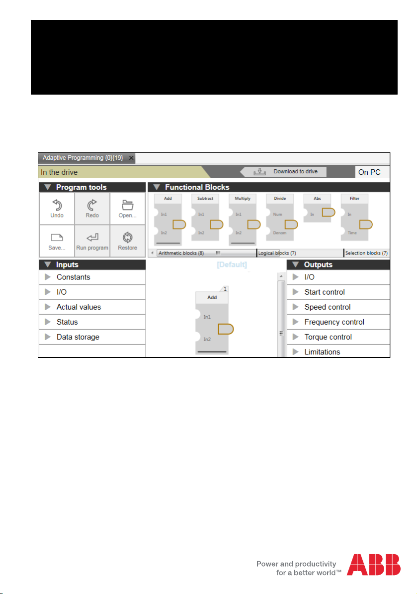
ABB industrial drives
Application guide
Adaptive Programming
Page 2

List of related manuals
Drive firmware manuals Code (English)
ACS880 primary control program firmware manual 3AUA0000085967
ACS380 machinery control program firmware
manual
Option manuals
Drive composer start-up and maintenance PC tool
User’s manual
You can find manuals and other product documents in PDF format on the Internet. See section
Document library on the Internet on the inside of the back cover. For manuals not available in
the Document library, contact your local ABB representative.
3AXD50000029275
3AUA0000094606
Page 3

Application guide
Adaptive Programming
Table of contents
2016 ABB Oy. All Rights Reserved.
3AXD50000028574 Rev C
EN
EFFECTIVE: 2016-03-14
Page 4

Page 5

Table of contents 5
Table of contents
List of related manuals . . . . . . . . . . . . . . . . . . . . . . . . . . . . . . . . . . . . . . . . . . . . . . . . . . . . . . . 2
1. Introduction to the guide
Contents of this chapter . . . . . . . . . . . . . . . . . . . . . . . . . . . . . . . . . . . . . . . . . . . . . . . . . . . . . . . 9
Applicability . . . . . . . . . . . . . . . . . . . . . . . . . . . . . . . . . . . . . . . . . . . . . . . . . . . . . . . . . . . . . . . . 9
Compatibility . . . . . . . . . . . . . . . . . . . . . . . . . . . . . . . . . . . . . . . . . . . . . . . . . . . . . . . . . . . . . . . 9
Safety instructions . . . . . . . . . . . . . . . . . . . . . . . . . . . . . . . . . . . . . . . . . . . . . . . . . . . . . . . . . . 10
Target audience . . . . . . . . . . . . . . . . . . . . . . . . . . . . . . . . . . . . . . . . . . . . . . . . . . . . . . . . . . . . 10
Purpose of the guide . . . . . . . . . . . . . . . . . . . . . . . . . . . . . . . . . . . . . . . . . . . . . . . . . . . . . . . . 10
Contents of the guide . . . . . . . . . . . . . . . . . . . . . . . . . . . . . . . . . . . . . . . . . . . . . . . . . . . . . . . 10
Related documents . . . . . . . . . . . . . . . . . . . . . . . . . . . . . . . . . . . . . . . . . . . . . . . . . . . . . . . . . 10
2. Adaptive programming
Contents of this chapter . . . . . . . . . . . . . . . . . . . . . . . . . . . . . . . . . . . . . . . . . . . . . . . . . . . . . . 11
Overview of Adaptive programming . . . . . . . . . . . . . . . . . . . . . . . . . . . . . . . . . . . . . . . . . . . . 11
Creating a sequence program . . . . . . . . . . . . . . . . . . . . . . . . . . . . . . . . . . . . . . . . . . . . . . . . . 12
Connecting the Adaptive program to a drive application . . . . . . . . . . . . . . . . . . . . . . . . . . . . . 12
Enabling/disabling Adaptive program . . . . . . . . . . . . . . . . . . . . . . . . . . . . . . . . . . . . . . . . . . . 12
Executing the Adaptive program . . . . . . . . . . . . . . . . . . . . . . . . . . . . . . . . . . . . . . . . . . . . . . . 13
Creating a backup/restore . . . . . . . . . . . . . . . . . . . . . . . . . . . . . . . . . . . . . . . . . . . . . . . . . . . . 13
Safety
3. Using PC tool interface
Contents of this chapter . . . . . . . . . . . . . . . . . . . . . . . . . . . . . . . . . . . . . . . . . . . . . . . . . . . . . . 15
Adaptive programming user interface . . . . . . . . . . . . . . . . . . . . . . . . . . . . . . . . . . . . . . . . . . . 15
Base and sequence programs . . . . . . . . . . . . . . . . . . . . . . . . . . . . . . . . . . . . . . . . . . . . . 17
Program tools . . . . . . . . . . . . . . . . . . . . . . . . . . . . . . . . . . . . . . . . . . . . . . . . . . . . . . . . . . 18
Functional blocks . . . . . . . . . . . . . . . . . . . . . . . . . . . . . . . . . . . . . . . . . . . . . . . . . . . . . . . 18
Inputs . . . . . . . . . . . . . . . . . . . . . . . . . . . . . . . . . . . . . . . . . . . . . . . . . . . . . . . . . . . . . . . . 19
Outputs . . . . . . . . . . . . . . . . . . . . . . . . . . . . . . . . . . . . . . . . . . . . . . . . . . . . . . . . . . . . . . . 21
Sequence states . . . . . . . . . . . . . . . . . . . . . . . . . . . . . . . . . . . . . . . . . . . . . . . . . . . . . . . . 22
State transition . . . . . . . . . . . . . . . . . . . . . . . . . . . . . . . . . . . . . . . . . . . . . . . . . . . . . . . . . 22
4. Creating an Adaptive program
Contents of this chapter . . . . . . . . . . . . . . . . . . . . . . . . . . . . . . . . . . . . . . . . . . . . . . . . . . . . . . 23
Creating a base program . . . . . . . . . . . . . . . . . . . . . . . . . . . . . . . . . . . . . . . . . . . . . . . . . . . . . 24
Creating a sequence program . . . . . . . . . . . . . . . . . . . . . . . . . . . . . . . . . . . . . . . . . . . . . . . . . 26
Downloading the adaptive program . . . . . . . . . . . . . . . . . . . . . . . . . . . . . . . . . . . . . . . . . . . . . 28
5. Program elements
Contents of this chapter . . . . . . . . . . . . . . . . . . . . . . . . . . . . . . . . . . . . . . . . . . . . . . . . . . . . . . 31
System inputs . . . . . . . . . . . . . . . . . . . . . . . . . . . . . . . . . . . . . . . . . . . . . . . . . . . . . . . . . . . . . 32
Parameter inputs . . . . . . . . . . . . . . . . . . . . . . . . . . . . . . . . . . . . . . . . . . . . . . . . . . . . . . . . 32
Constants . . . . . . . . . . . . . . . . . . . . . . . . . . . . . . . . . . . . . . . . . . . . . . . . . . . . . . . . . . . . . 32
Page 6

6 Table of contents
Inputs/outputs . . . . . . . . . . . . . . . . . . . . . . . . . . . . . . . . . . . . . . . . . . . . . . . . . . . . . . . . . 32
Actual values . . . . . . . . . . . . . . . . . . . . . . . . . . . . . . . . . . . . . . . . . . . . . . . . . . . . . . . . . . 33
Status . . . . . . . . . . . . . . . . . . . . . . . . . . . . . . . . . . . . . . . . . . . . . . . . . . . . . . . . . . . . . . . . 33
Data storage . . . . . . . . . . . . . . . . . . . . . . . . . . . . . . . . . . . . . . . . . . . . . . . . . . . . . . . . . . . 33
System outputs . . . . . . . . . . . . . . . . . . . . . . . . . . . . . . . . . . . . . . . . . . . . . . . . . . . . . . . . . . . . 33
Parameter outputs . . . . . . . . . . . . . . . . . . . . . . . . . . . . . . . . . . . . . . . . . . . . . . . . . . . . . . 33
I/O . . . . . . . . . . . . . . . . . . . . . . . . . . . . . . . . . . . . . . . . . . . . . . . . . . . . . . . . . . . . . . . . . . 34
Start control . . . . . . . . . . . . . . . . . . . . . . . . . . . . . . . . . . . . . . . . . . . . . . . . . . . . . . . . . . . 34
Speed control . . . . . . . . . . . . . . . . . . . . . . . . . . . . . . . . . . . . . . . . . . . . . . . . . . . . . . . . . . 34
Frequency control . . . . . . . . . . . . . . . . . . . . . . . . . . . . . . . . . . . . . . . . . . . . . . . . . . . . . . 35
Torque control . . . . . . . . . . . . . . . . . . . . . . . . . . . . . . . . . . . . . . . . . . . . . . . . . . . . . . . . . 35
Limitations . . . . . . . . . . . . . . . . . . . . . . . . . . . . . . . . . . . . . . . . . . . . . . . . . . . . . . . . . . . . 35
Events . . . . . . . . . . . . . . . . . . . . . . . . . . . . . . . . . . . . . . . . . . . . . . . . . . . . . . . . . . . . . . . 35
Process PID . . . . . . . . . . . . . . . . . . . . . . . . . . . . . . . . . . . . . . . . . . . . . . . . . . . . . . . . . . . 35
Function block specifications . . . . . . . . . . . . . . . . . . . . . . . . . . . . . . . . . . . . . . . . . . . . . . . . . 36
Abs . . . . . . . . . . . . . . . . . . . . . . . . . . . . . . . . . . . . . . . . . . . . . . . . . . . . . . . . . . . . . . . . . . 36
Add . . . . . . . . . . . . . . . . . . . . . . . . . . . . . . . . . . . . . . . . . . . . . . . . . . . . . . . . . . . . . . . . . . 37
AND . . . . . . . . . . . . . . . . . . . . . . . . . . . . . . . . . . . . . . . . . . . . . . . . . . . . . . . . . . . . . . . . . 38
Bit get . . . . . . . . . . . . . . . . . . . . . . . . . . . . . . . . . . . . . . . . . . . . . . . . . . . . . . . . . . . . . . . . 39
Bitwise AND . . . . . . . . . . . . . . . . . . . . . . . . . . . . . . . . . . . . . . . . . . . . . . . . . . . . . . . . . . . 41
Bitwise OR . . . . . . . . . . . . . . . . . . . . . . . . . . . . . . . . . . . . . . . . . . . . . . . . . . . . . . . . . . . . 42
Bitwise XOR . . . . . . . . . . . . . . . . . . . . . . . . . . . . . . . . . . . . . . . . . . . . . . . . . . . . . . . . . . . 43
Divide . . . . . . . . . . . . . . . . . . . . . . . . . . . . . . . . . . . . . . . . . . . . . . . . . . . . . . . . . . . . . . . . 44
Equal . . . . . . . . . . . . . . . . . . . . . . . . . . . . . . . . . . . . . . . . . . . . . . . . . . . . . . . . . . . . . . . . 45
Filter . . . . . . . . . . . . . . . . . . . . . . . . . . . . . . . . . . . . . . . . . . . . . . . . . . . . . . . . . . . . . . . . . 46
Greater than . . . . . . . . . . . . . . . . . . . . . . . . . . . . . . . . . . . . . . . . . . . . . . . . . . . . . . . . . . . 47
Less than . . . . . . . . . . . . . . . . . . . . . . . . . . . . . . . . . . . . . . . . . . . . . . . . . . . . . . . . . . . . . 48
Limit . . . . . . . . . . . . . . . . . . . . . . . . . . . . . . . . . . . . . . . . . . . . . . . . . . . . . . . . . . . . . . . . . 49
Max . . . . . . . . . . . . . . . . . . . . . . . . . . . . . . . . . . . . . . . . . . . . . . . . . . . . . . . . . . . . . . . . . 50
Min . . . . . . . . . . . . . . . . . . . . . . . . . . . . . . . . . . . . . . . . . . . . . . . . . . . . . . . . . . . . . . . . . . 51
Multiply . . . . . . . . . . . . . . . . . . . . . . . . . . . . . . . . . . . . . . . . . . . . . . . . . . . . . . . . . . . . . . . 52
NOT . . . . . . . . . . . . . . . . . . . . . . . . . . . . . . . . . . . . . . . . . . . . . . . . . . . . . . . . . . . . . . . . . 53
OR . . . . . . . . . . . . . . . . . . . . . . . . . . . . . . . . . . . . . . . . . . . . . . . . . . . . . . . . . . . . . . . . . . 54
PI . . . . . . . . . . . . . . . . . . . . . . . . . . . . . . . . . . . . . . . . . . . . . . . . . . . . . . . . . . . . . . . . . . . 55
Ramp . . . . . . . . . . . . . . . . . . . . . . . . . . . . . . . . . . . . . . . . . . . . . . . . . . . . . . . . . . . . . . . . 57
Select boolean . . . . . . . . . . . . . . . . . . . . . . . . . . . . . . . . . . . . . . . . . . . . . . . . . . . . . . . . . 59
Select value . . . . . . . . . . . . . . . . . . . . . . . . . . . . . . . . . . . . . . . . . . . . . . . . . . . . . . . . . . . 60
Set bits 0-7 . . . . . . . . . . . . . . . . . . . . . . . . . . . . . . . . . . . . . . . . . . . . . . . . . . . . . . . . . . . . 61
Set bits 8-15 . . . . . . . . . . . . . . . . . . . . . . . . . . . . . . . . . . . . . . . . . . . . . . . . . . . . . . . . . . . 62
Square root . . . . . . . . . . . . . . . . . . . . . . . . . . . . . . . . . . . . . . . . . . . . . . . . . . . . . . . . . . . 63
SR . . . . . . . . . . . . . . . . . . . . . . . . . . . . . . . . . . . . . . . . . . . . . . . . . . . . . . . . . . . . . . . . . . 64
Subtract . . . . . . . . . . . . . . . . . . . . . . . . . . . . . . . . . . . . . . . . . . . . . . . . . . . . . . . . . . . . . . 65
Switch boolean . . . . . . . . . . . . . . . . . . . . . . . . . . . . . . . . . . . . . . . . . . . . . . . . . . . . . . . . . 66
Switch value . . . . . . . . . . . . . . . . . . . . . . . . . . . . . . . . . . . . . . . . . . . . . . . . . . . . . . . . . . . 68
Timer . . . . . . . . . . . . . . . . . . . . . . . . . . . . . . . . . . . . . . . . . . . . . . . . . . . . . . . . . . . . . . . . 70
Trigger down . . . . . . . . . . . . . . . . . . . . . . . . . . . . . . . . . . . . . . . . . . . . . . . . . . . . . . . . . . 73
Trigger up . . . . . . . . . . . . . . . . . . . . . . . . . . . . . . . . . . . . . . . . . . . . . . . . . . . . . . . . . . . . . 74
T_off . . . . . . . . . . . . . . . . . . . . . . . . . . . . . . . . . . . . . . . . . . . . . . . . . . . . . . . . . . . . . . . . . 75
T_on . . . . . . . . . . . . . . . . . . . . . . . . . . . . . . . . . . . . . . . . . . . . . . . . . . . . . . . . . . . . . . . . . 76
XOR . . . . . . . . . . . . . . . . . . . . . . . . . . . . . . . . . . . . . . . . . . . . . . . . . . . . . . . . . . . . . . . . . 77
Page 7

Table of contents 7
Further information
Product and service inquiries . . . . . . . . . . . . . . . . . . . . . . . . . . . . . . . . . . . . . . . . . . . . . . . . . 79
Product training . . . . . . . . . . . . . . . . . . . . . . . . . . . . . . . . . . . . . . . . . . . . . . . . . . . . . . . . . . . . 79
Providing feedback on ABB Drives manuals . . . . . . . . . . . . . . . . . . . . . . . . . . . . . . . . . . . . . . 79
Document library on the Internet . . . . . . . . . . . . . . . . . . . . . . . . . . . . . . . . . . . . . . . . . . . . . . . 79
Page 8

8 Table of contents
Page 9

Introduction to the guide 9
1
Introduction to the guide
Contents of this chapter
This chapter gives general information on the guide.
Applicability
This guide applies to the following drive programs and software. For version details,
see the Compatibility list:
• ACS880 primary control program
• ACS380 machinery control program
• Drive composer pro
Compatibility
This guide complies with the following drive application programs in which the
Adaptive programming feature is included.
Drive application programs Version Other details
ACS880 primary control
program
ACS380 machinery control
program
Drive composer pro 1.9 or later Microsoft Windows 7 or newer
Note: The available features may differ depending on both the Drive composer pro
and drive versions
2.20 or later -
1.60 or later -
Page 10

10 Introduction to the guide
Safety instructions
Follow all safety instructions delivered with the drive.
• Read the complete safety instructions before you install, commission, or use the
drive. The complete safety instructions are delivered with the drive as either part
of the Hardware manual, or, in the case of ACS880 multidrives, as a separate
document.
• Read the software function specific warnings and notes before changing the
default settings of the function. For each function, the warnings and notes are
given in the Firmware Manual in the subsection describing the related user
adjustable parameters.
Target audience
This guide is intended for people who design, commission, or operate the drive
system.
Purpose of the guide
This guide is used together with the firmware manual of the drive application
program.The firmware manual contains basic information on drive parameters
including the parameters needed for Adaptive programming.
This guide gives the following information on Adaptive programming:
• what is Adaptive programming
• how to build a adaptive program
• how the function blocks operate
• how to use the system inputs and outputs
• how to use the program states
Contents of the guide
This guide contains the following chapters:
Adaptive programming provides the overview on Adaptive programming.
Using PC tool interface describes the user interface elements for creating an
Adaptive program in the PC tool software.
Creating an Adaptive program describes how to create a base program and a
sequence program. It also describes how to download the program to the drive.
Program elements describes the function blocks used for Adaptive programming.
Related documents
See the List of related manuals on the inside of the front cover.
Page 11

Adaptive programming 11
2
Adaptive programming
Contents of this chapter
This chapter provides an overview of Adaptive programming and how to use the
Adaptive program.
Overview of Adaptive programming
Adaptive programming is used to customize the operation of a drive in case the drive
parameter setting is not sufficient. The Adaptive program is built with standard
function blocks included in the drive firmware. The program consists of the following
elements:
• A predefined list of inputs for getting information from the drive parameters to use
in the Adaptive program.
• A predefined list of outputs that defines parameters where it is possible to write
from the Adaptive program.
• A collection of states in which each state has its own block program, including
inputs, outputs and state transition elements
Standard function blocks (for example ADD, AND) are used to create an executable
Adaptive program. The maximum size of an Adaptive program is approximately 20
standard function blocks, depending on the block types used and the number of
predefined inputs and outputs utilized in the program. The standard function blocks
available are presented in Program elements (page 31). Numerical function blocks
use floating point numbers in the calculations.
Adaptive program is created using the Drive composer pro software with which the
program can be downloaded to the drive and started. By default, Adaptive program is
started when the drive is powered On, if the program already exists in the drive.
See the below sections on how to use the Adaptive program.
Page 12

12 Adaptive programming
Creating a sequence program
Adaptive program consists of a collection of states for creating a sequence program.
When the program is running, there is always one state active and the corresponding
program is executed until another state is active. In addition to the states there is also
a base program that executes in parallel to the active state.
The state changes are controlled with state transition elements that can be connected
to function block outputs. State transition takes place after the full execution cycle of
the program during which the value of any corresponding output becomes true. In
case multiple state transitions are true during a single execution cycle, then the one
that is connected to the smallest numbered block is triggered. See the example
program execution.
See also Creating a sequence program on page 26 and Downloading the adaptive
program on page 28.
Connecting the Adaptive program to a drive application
Adaptive program is connected to a drive application through predefined system
inputs and outputs. Drive provides the available inputs and outputs and sets the
pointer parameter values accordingly based on the created program.
When the predefined output (value/bit pointer parameter) is written to from the
Adaptive program, the parameter is write protected and it is not changed in the
parameter table. The control panel and Drive composer pro shows a text in the
pointer parameter to indicate that the parameter is connected to the Adaptive
program.
Enabling/disabling Adaptive program
The Adaptive program function can be enabled or disabled with the drive parameter
96.70 Disable Adaptive program.
When Adaptive program is enabled, the program can be put to running mode in the
following conditions:
• when drive is powered On
• after a macro/user set is changed
• after a restore operation
• when a clear all and restore to defaults parameter operation (large parameter
operations) is done
• when a run command is given from the PC tool.
Page 13

Adaptive programming 13
When Adaptive program is disabled, the situation is similar to a drive without
Adaptive program. The following operations are not possible:
• Adaptive program cannot be put to running mode when the drive is powered On
• Adaptive program cannot be edited or put to running mode from Drive composer
pro.
Executing the Adaptive program
Adaptive program is executed on firmware time level. The parameter 7.30 Adaptive
program status shows the status of the Adaptive program. The program can be edited
only when the drive is in Stopped state. While editing the program, the Start inhibit is
On, so that the drive cannot be started.
Note: For time level actual value, refer firmware manual(s) in the List of related
manuals.
The Adaptive program executes the function blocks in numerical order with all blocks
on the same time level. This cannot be changed by the user. The user can only do the
following tasks:
• build a program using the standard blocks and connections
• change the numbering of the blocks by moving them to different positions
• select the operation mode of the program (run/edit).
If Adaptive program in the drive is not compatible or corrupted, the fault 64A6h
Adaptive program is activated. The extension code of the fault explains the detail of
the problem with the Adaptive program.
Creating a backup/restore
Adaptive program can be saved to the backup file and restored. The program starts
automatically after the restore operation, unless the parameter 96.70 Disable
Adaptive program has such a value that after the restore operation the Adaptive
program shall not be put to running mode.
Page 14

14 Adaptive programming
Page 15

Using PC tool interface 15
3
Using PC tool interface
Contents of this chapter
This chapter describes the main user interface elements of PC tool for Adaptive
programming.
Adaptive programming user interface
The main user interface of Adaptive programming consists of the following sections:
• Base and sequence programs
• Program tools
• Functional blocks
• Inputs
• Outputs
• Sequence states
• State transition.
Page 16
16 Using PC tool interface
The working area can be used either with tab or floating window. The selection
between tab and floating window can be made using Drive composer pro View menu.
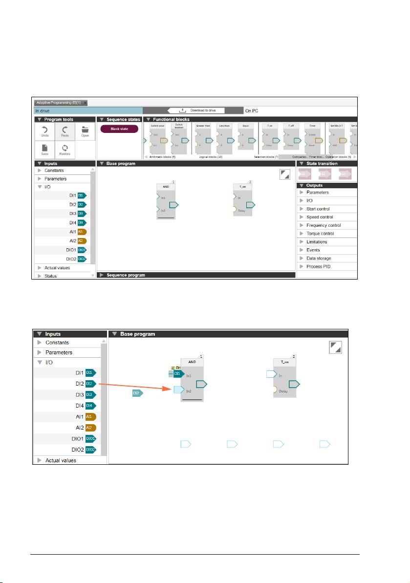
The figure below shows the user interface with tabbed window.
Figure 1. Adaptive programming user interface
Page 17
Using PC tool interface 17
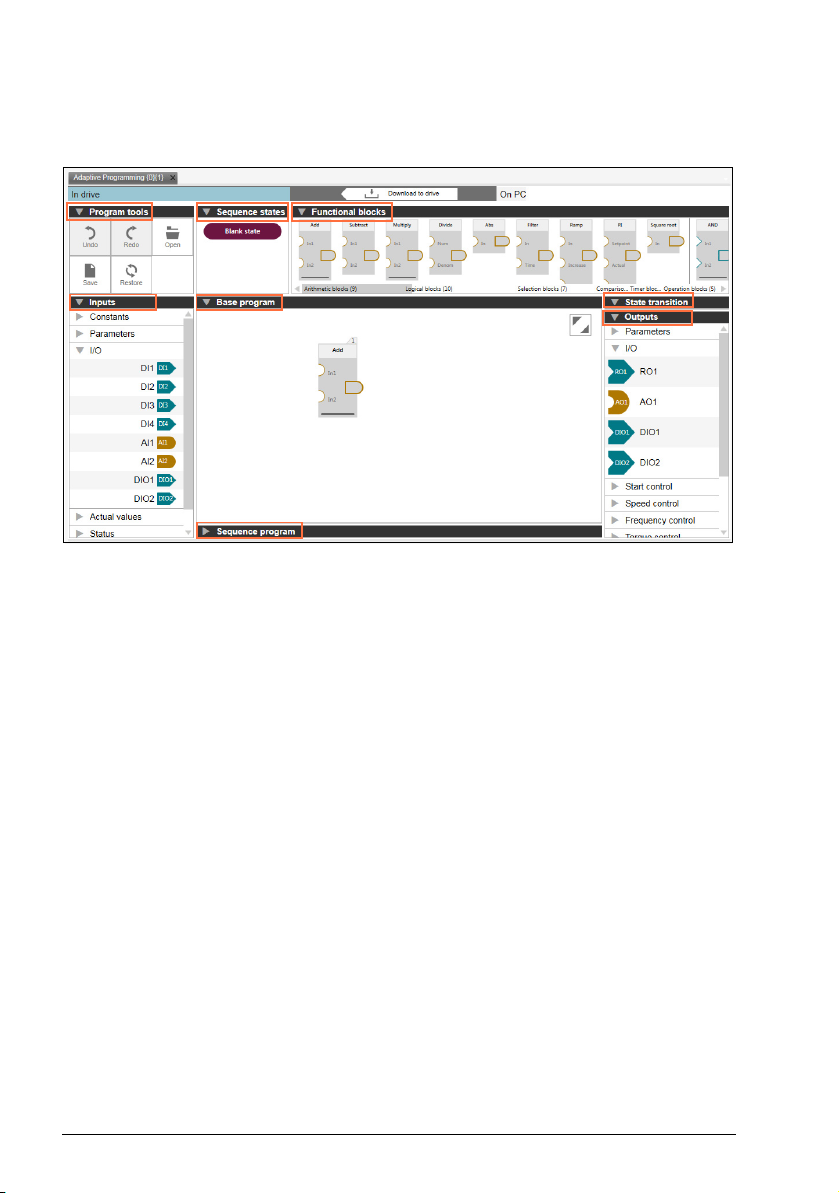
Base and sequence programs
There are separate canvases for creating base and sequence programs. The
required canvas can be expanded or collapsed. See the above Adaptive
programming user interface.
• The base program canvas can be used to create a base program with function
blocks. The user can drag and drop the desired function blocks to build a base
program. See Creating a base program on page 24.
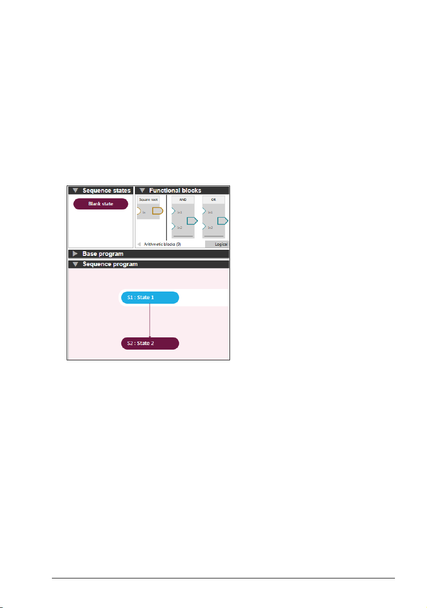
• The sequence program canvas can be used to create a sequence program. The
user can drag and drop the desired amount of states to build a sequence
program. See Creating a sequence program on page 26.
Figure 2. Sequence program user interface
Page 18

18 Using PC tool interface
Program tools
The program tools contains the following options:
• Undo: Erases the last change made and reverts it to an older state
• Redo: Reverses the undo or advances to a more current state
• Open: Opens a program from locally saved file
• Save: Saves the active program to a local file (.dcap format)
• Restore: Restores the default program.
See Adaptive programming user interface on page 16.
Functional blocks
Functional blocks of Adaptive programming are grouped into categories and are
shown on a horizontal shelf. The scroll bar shows category labels and indicates the
current view. The blocks are quickly accessible. The user can drag and drop the
required blocks to the canvas. See Adaptive programming user interface on page 16.
The functional block consists of the following categories:
• Arithmetic blocks
• Logical blocks
• Selection blocks
• Comparison blocks
• Timer blocks
• Operation blocks.
Page 19
Using PC tool interface 19
Inputs
The pre-defined inputs are categorized into groups. Note that the available groups
and inputs are dependent on the drive type. Typical examples are:
•Constants
•I/O
• Actual values.
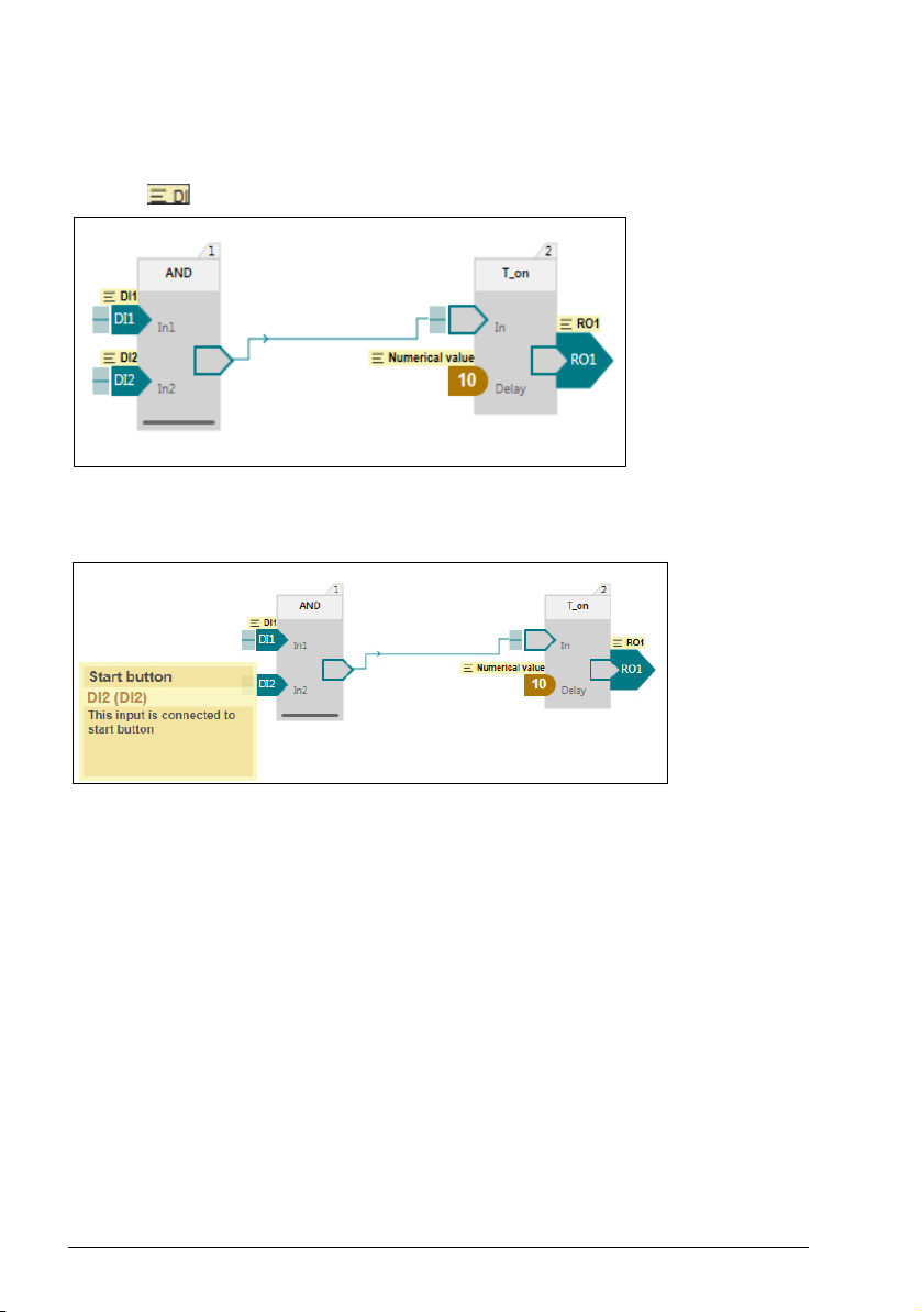
The same input can be used multiple times in the same program. Hovering over an
input on the shelf highlights every instance of that input on the canvas, so you can
easily locate where the input is used in the program.
Figure 3. Inputs
Page 20
20 Using PC tool interface
Editing the input labels
You can edit the input labels and add a comment.
1. Click label in the functional block input.
Figure 4. Editing label
2. Edit the label and add the comment as desired.
Figure 5. Editing label and comment
For more information on Input descriptions, refer firmware manual(s) in the List of
related manuals.
Page 21
Using PC tool interface 21
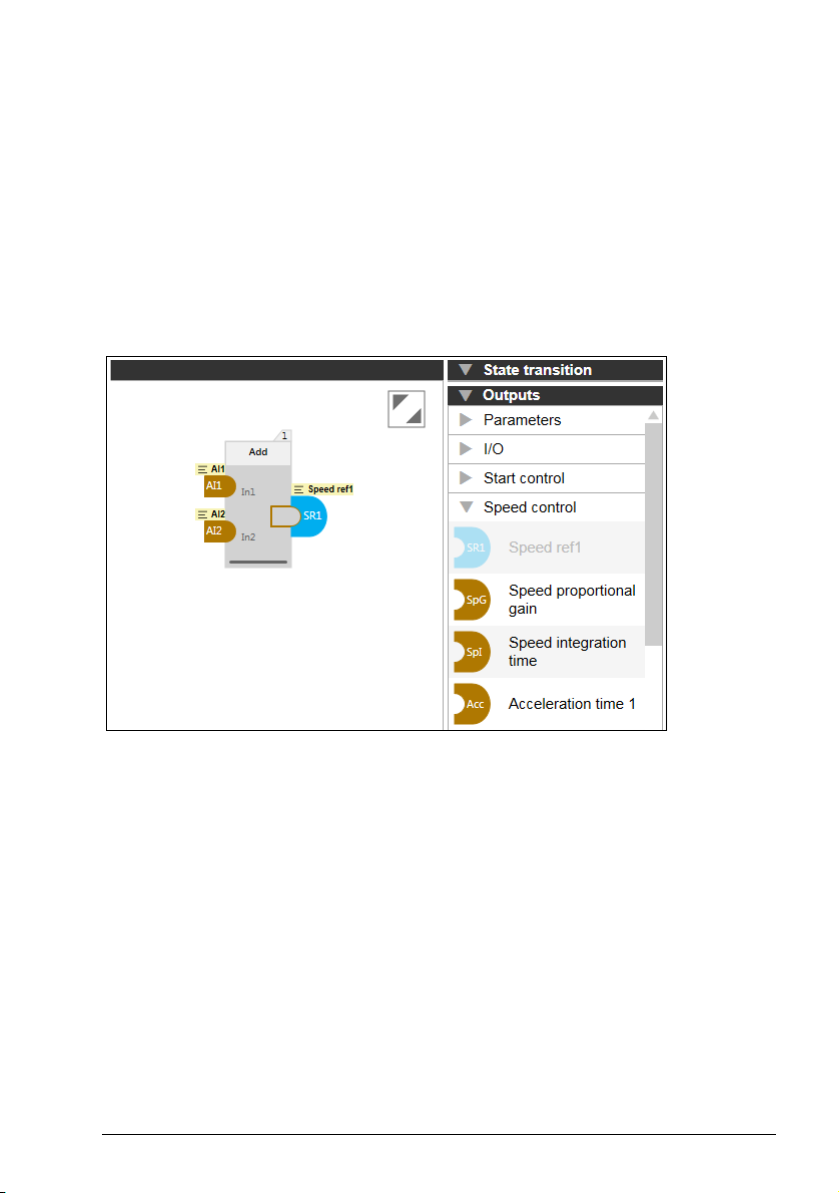
Outputs
The pre-defined outputs are categorized into groups. Note that the available groups
and outputs are dependent on the drive type. Typical examples are:
• Parameters
• I/O
• Start control
• Speed control.
Each output can be used only once in the program. After you drag and drop an output
to the canvas, it is faded on the shelf.
Figure 6. Outputs
For more information on output descriptions, refer firmware manual(s) in the List of
related manuals.
Page 22
22 Using PC tool interface
Sequence states
The sequence states contains a:
• Blank state: adds a new empty state to the sequence program.
You can drag-and-drop this empty state any number of times to the sequence
program canvas and rename the state in the program.
See Adaptive programming user interface on page 16.
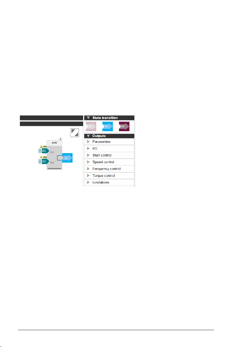
State transition
State transition element is used to control the sequence of state transitions when
connected to boolean type block outputs. There can be several state transition
elements used in a single state.
Figure 7. State transition
Page 23

Creating an Adaptive program 23
4
Creating an Adaptive program
Contents of this chapter
This chapter describes how to create an Adaptive program and download the
program to the drive.
You can do the following:
• Create a base program using function blocks. See Creating a base program on
page 24.
• Optionally create a sequence program using states. See Creating a sequence
program on page 26.
• Download the program to the drive. See Downloading the adaptive program on
page 28.
Page 24
24 Creating an Adaptive program
Creating a base program
To create a base program using function blocks, proceed as follows:
1. Drag-and-drop the desired function blocks to the base program canvas.
Figure 8. Function block
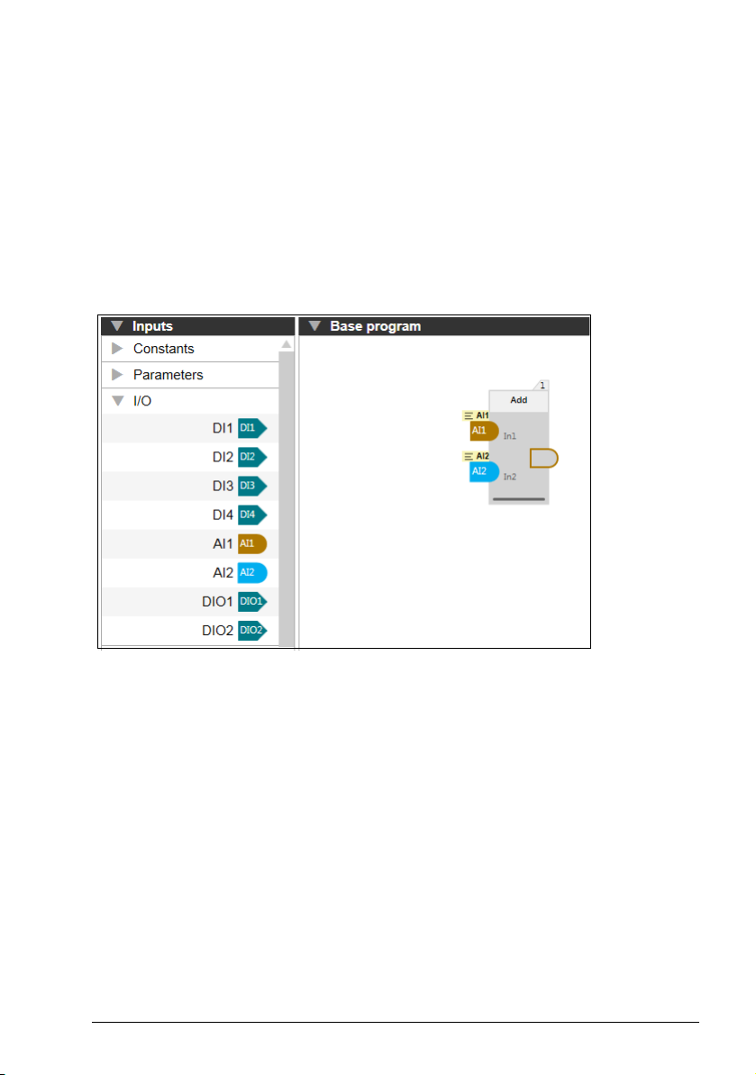
2. Drag-and-drop the desired inputs from the Inputs categories to the function
block(s).
Figure 9. Adding inputs
Page 25
Creating an Adaptive program 25
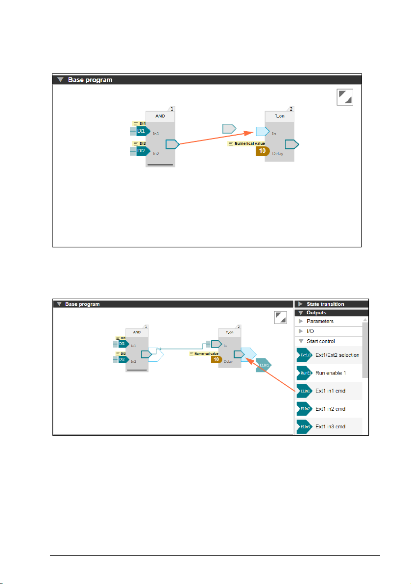
3. Drag-and-drop the desired connections from the block outputs to other function
block(s).
Figure 10. Adding outputs
4. Drag-and-drop the desired output from the Outputs categories to the function
block(s).
Figure 11. Adding outputs
Similarly, you can create programs as desired by adding multiple function blocks
using inputs and outputs.
Page 26

26 Creating an Adaptive program
Creating a sequence program
To create a sequence program using states, proceed as follows:
1. Open the Sequence Program canvas.
2. Drag-and-drop the desired amount of states to the sequence.
Figure 12. Sequence program states
3. Select the state and create desired block program for each state.
Figure 13. Block program in selected state
Page 27

Creating an Adaptive program 27
4. Drag-and-drop the desired state transitions to each state.
Figure 14. State transitions
Page 28
28 Creating an Adaptive program
Downloading the adaptive program
After creating a base program and optionally a sequence program, you can download
the program to a drive and run the program.
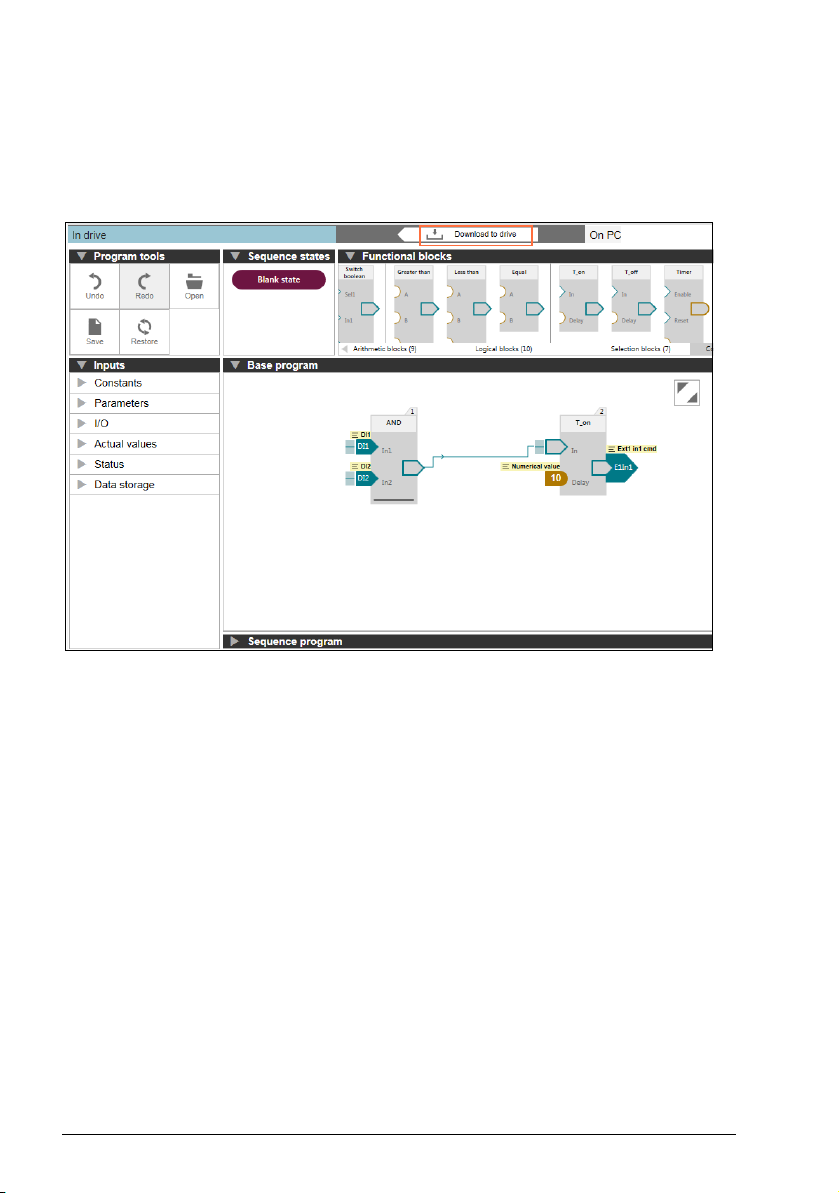
1. Click Download to drive.
Figure 15. Downloading to drive
Page 29

Creating an Adaptive program 29
The program is downloaded to the drive.
Figure 16. Program downloaded to a drive
2. In the Program tools, click Run program to start the program.
3. Open the Sequence program canvas to view the sequence program.
Figure 17. Sequence program
Page 30

30 Creating an Adaptive program
After downloading the program to the drive, you can
• click Edit program to stop the program and start editing
or
• click Save to save the adaptive program to a local file (.dcap format).
Page 31

Program elements 31
5
Program elements
Contents of this chapter
This chapter describes system inputs, outputs and function blocks available in the
master control program for Adaptive programming.
Note: The information in this chapter is drive-specific and should be confirmed from
the respective firmware manual(s).
Page 32

32 Program elements
System inputs
The below mentioned system inputs are examples only.
Parameter inputs
System inputs have new type of parameter inputs.
• Boolean parameter input is for reading the value of a bit from a parameter (for
example command or status word)
• Numeric parameter input is for reading the value of a parameter.
Constants
Constants consists of Numerical and Boolean constant input values. These constant
inputs can be reused in different blocks by changing their values.
For example: Numerical value and Boolean value.
Inputs/outputs
Analog inputs
Analog inputs can be filtered, inverted or scaled with parameter configuration (i.e. not
in Adaptive programming).
Analog inputs can be independently set as voltage or current input by a jumper. Each
input can be filtered, inverted or scaled.
The drive can be set to perform an action if the value of an analog input moves out of
a predefined range.
Digital inputs and outputs
Digital inputs and outputs can be set as either an input or an output.
Digital input/output DIO1 can be used as a frequency input, DIO2 as a frequency
output.
For example: AI1, AI2, DI1, DI2, DIO1, DIO2 etc.
Page 33

Program elements 33
Actual values
Basic signals for monitoring the drive.
For example: Motor speed, Output frequency, Motor current and so on.
Status
Drive status word.
Example: Enabled, inhibited, Ready to start etc.
Data storage
Data storage parameters are reserved for data storage. These parameters are
unconnected by default and can be used for linking, testing and commissioning
purpose.
For example: Data storage 1 real32, Data storage 2 real32 etc.
For more information on Input descriptions, refer firmware manual(s) in List of related
manuals.
System outputs
The below mentioned system outputs are examples only.
Parameter outputs
System outputs have a new type of parameter outputs.
• Boolean parameter output is for writing a Boolean block output to a parameter.
The parameter gets either value one or zero.
• Numerical parameter output is for writing a Numerical block output to a parameter.
You can select the parameter for the input or output either from a list or type the
parameter manually.
Page 34

34 Program elements
Reading and writing parameters in the drive
The block output value is written to the parameter only when the value changes. The
written parameter values are not saved over power down of the drive.
For efficiency, the parameter reading and writing is made in the internal format. In
case of some parameters, it is possible that the block input shows a different value
than the corresponding parameter.
I/O
Analog outputs
Analog outputs can be filtered, inverted or scaled with parameter configuration (i.e
not in Adaptive programming).
Relay outputs
The signal to be indicated by the outputs can be selected by parameters.
Digital inputs and outputs
Digital input/output DIO1 can be used as a frequency input, DIO2 as a frequency
output.
For example: AO1, AO2, RO1, RO2, RO3, DIO1 and DIO2.
Start control
Operating mode
The two external control locations, EXT1 and EXT2, are available. The user can
select the sources of the start and stop commands separately for each location.
Run enable
The source of the external run enable signal. If the run enable signal is switched off,
the drive will not run.
Fault reset
The drive can automatically reset itself after overcurrent, overvoltage, undervoltage
and external faults.
For example: Ext1/Ext2 selection, Run enable 1, Fault reset etc.
Speed control
The output of the speed reference selection block. The motor follows a speed
reference given to the drive.
For example: Speed ref1, Speed ref2 and Speed additive 1.
Page 35

Program elements 35
Frequency control
The output of the frequency reference selection block. The motor follows a frequency
reference given to the drive. Frequency control is only available in scalar motor
control mode.
For example: Frequency ref1, Frequency ref2 etc.
Torque control
The output of the torque reference selection block. Motor torque follows a torque
reference given to the drive.
For example: Torque ref1, Torque ref2 and Torque additive 2.
Limitations
Defines the source of maximum torque limit for the drive.
For example: Minimum torque 2 and Maximum torque 2.
Events
Defines the source of external events.
For example: External event 1, External event 2 etc.
Process PID
Selects the source that determines whether process PID parameter set is used.
For example: Set 1 setpoint 1, Set 1 feedback 1, Set 1 tracking mode etc.
For more information on output descriptions, refer firmware manual(s) in List of
related manuals.
Page 36

36 Program elements
Function block specifications
You can adjust the number of inputs by dragging the bottom line in the function block.
Note: Function blocks which do not contain bottom line cannot be adjusted.
Abs
Calculates absolute value.
Output:
Name Type Default value
Out Float 0
Input: 1
Name Type Default value Function
In Float 0 Block input
Block function
Block calculates absolute value of value in input In. Output = I In I.
Exceptional cases
Block input is not connected. Input has a default value.
Page 37

Add
Adds n inputs and outputs result.
Output:
Name Type Default value
Out Float 0
Inputs: 2-8
Program elements 37
Default inputs: 2
Name Type Default value Function
In1 - In8 Float 0 Provides values to add
Block function
Output = In1 + In2 +...+ In8
Exceptional cases
• Inputs which are not connected are added as default value.
• Overflow to positive side: output is limited to Max float.
• Overflow to the negative side: output is limited to negative Max float.
• Underflow: value 0 is kept at output.
Page 38

38 Program elements
AND
Performs logic AND.
Output
Name Type Default value
Out Boolean 0
Inputs: 2-8
Default inputs: 2
Name Type Default value Function
In1 - In8 Boolean N/A Block inputs
Block function
Function block performs logical conjunction operation with inputs.
Out = In1 & In2 & … & In8.
The truth table of AND operation is below. Example uses two inputs. Same logic can
be applied to other inputs. Output is 1 (true) if and only if all inputs have value 1 (true).
In1 In2 Out
00 0
01 0
10 0
11 1
Exceptional cases
• Inputs which are not connected have no effect on the output.
• If some inputs are connected and others are not, only the connected inputs
are evaluated.
Page 39
Program elements 39
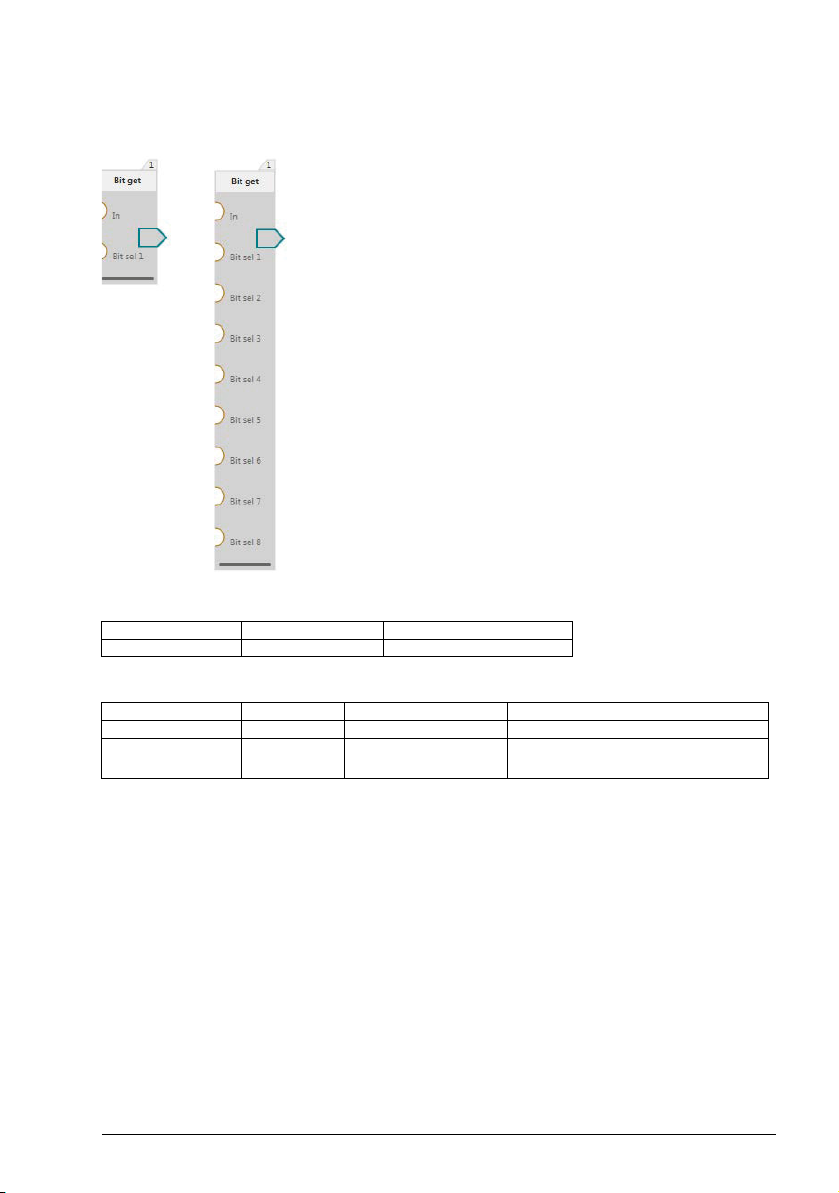
Bit get
Performs logic OR operation with selected bits from inputs.
Output
Name Type Default value
Out Boolean 0
Inputs: 2-9
Name Type Default value Function
In Float 0 Value to read bits
Bit sel 1 - 8 Float N/A Provides number of bits to
be selected from input value.
Block function
Basic functionality of the block is to get the value of the defined bit. In case several
bits are defined then values of these bits are retrieved and OR operation is executed
with these to get the block output value.
Bits 0 - 15 can be selected.
For example, in case only Bit sel 1 is connected then Out = val1. If Bit sel 1 and 2 are
connected then Out = val1 OR val2, where val1 - value of bit selected by Bit sel 1
input and val2 - value of bit selected by Bit sel 2 input.
Page 40

40 Program elements
Exceptional cases
• Bit sel input is not connected. Bit defined by this input is skipped.
• If entered bit sel value > 15, bit 15 is selected.
• If bit sel < 0 then bit 0 is selected.
• If input In is not connected, it gets default value.
• An input In value that is either negative or larger than (2^31)-1 is set to default
value 0.
Page 41

Program elements 41
Bitwise AND
ANDs the lowest 16 separate bits of the input values and outputs the combination as
float.
Output
Name Type Default value
Out Float 0
Inputs: 2-8
Name Type Default value Function
In1 - In8 Float N/A Provides an input value.
Block function
Connected inputs are rounded to the nearest integer after which the AND operation is
performed on them. The lowest 16 bits of the result is taken, converted to float and
written to output.
Exceptional cases
• An input value that is either negative or larger than (2^31)-1 is set to default value
0.
• If only 1 input is connected then that input is rounded and sent to the output.
Page 42

42 Program elements
Bitwise OR
ORs the lowest 16 separate bits of the input values and outputs the combination as
float.
Output
Name Type Default value
Out Float 0
Inputs: 2-8
Name Type Default value Function
In1 - In8 Float 0 Provides an input value.
Block function
Inputs are rounded to the nearest integer after which the OR operation is performed
on them. The lowest 16 bits of the result is taken, converted to float and written to
output.
Exceptional cases
• An input value that is either negative or larger than (2^31)-1 is set to default value
0.
• If only 1 input is connected then that input is rounded and sent to the output.
• Disconnected inputs have default value 0.
Page 43

Program elements 43
Bitwise XOR
XORs the lowest 16 separate bits of the input values and outputs the combination as
float.
Output
Name Type Default value
Out Float 0
Inputs: 2
Name Type Default value Function
In1 Float 0 Provides an input value.
In2 Float 0 Provides an input value.
Block function
Inputs are rounded to the nearest integer after which the XOR operation is performed
on them. The lowest 16 bits of the result is taken, converted to float and written to
output.
Exceptional cases
• An input value that is either negative or larger than (2^31)-1 is set to default value
0.
• If only 1 input is connected then that input is rounded and sent to the output.
Page 44

44 Program elements
Divide
Divides block inputs.
Output:
Name Type Default value
Out Float 0
Inputs: 2
Name Type Default value Function
Num Float 0 Dividend
Denom Float 0 Divisor
Block function
Output = In1 / In2
Dividing by zero will set block output to zero.
Exceptional cases
• Inputs which are not connected are assigned with default values.
• Overflow to positive side: output is limited to Max float.
• Overflow to the negative side: output is limited to negative Max float.
• Underflow: value 0 is kept at output.
Page 45

Program elements 45
Equal
Checks if values at inputs are equal.
Output
Name Type Default value
Out Boolean 0
Inputs: 2
Name Type Default value Function
A Float 0 First comparison
B Float 0 Second comparison
Block function
Block compares the whole number parts of numbers in A and B. Behavior of the block
can be seen in table below.
Condition Out
A and B are equal 1
A and B are not equal 0
Inputs are rounded before comparison. Only whole number part of the inputs are
compared.
value
value
For example, if value 70.5 is in input, it will be compared as 71. If value 70.4 is in input
it will be compared as 70. Rounding of negative numbers works as illustrated in the
following example. -70.4 rounds to -70. -70.5 rounds to -71.
Exceptional cases
Inputs which are not connected will have a default value.
Page 46

46 Program elements
Filter
Filters input for a defined length of time and then outputs it.
Output:
Name Type Default value
Out Float 0
Inputs: 2
Name Type Default value Function
In Float 0 Signal to be filtered
Time Float 0 Filter time constant
in seconds
Block function
This block is a single pole low - pass filter. Input signal In is filtered using provided
time constant Time. The following equation is used for internal calculations.
Coefficient = TimeLevel / (TimeLevel + Time)
Out[i] = Coefficient * (In[i] – Out[i - 1]) + Out[i - 1]
Where:
Variable Function
Out [i] Current calculated output value
Out [i - 1] Previous output value of the filter from previous time cycle
In [i] Current input value
Timelevel Value of timelevel that the program is running at.
This function is a discrete model for single pole low - pass filter.
Exceptional cases
• Time constant Time < timelevel or negative constant is provided. Filter does
not filter input signal. Input is written to output unaltered. Time constant is
evaluated to 0.
• In is not connected - Input gets default value.
• Time constant is not connected - assumed to have default value.
Page 47
Program elements 47
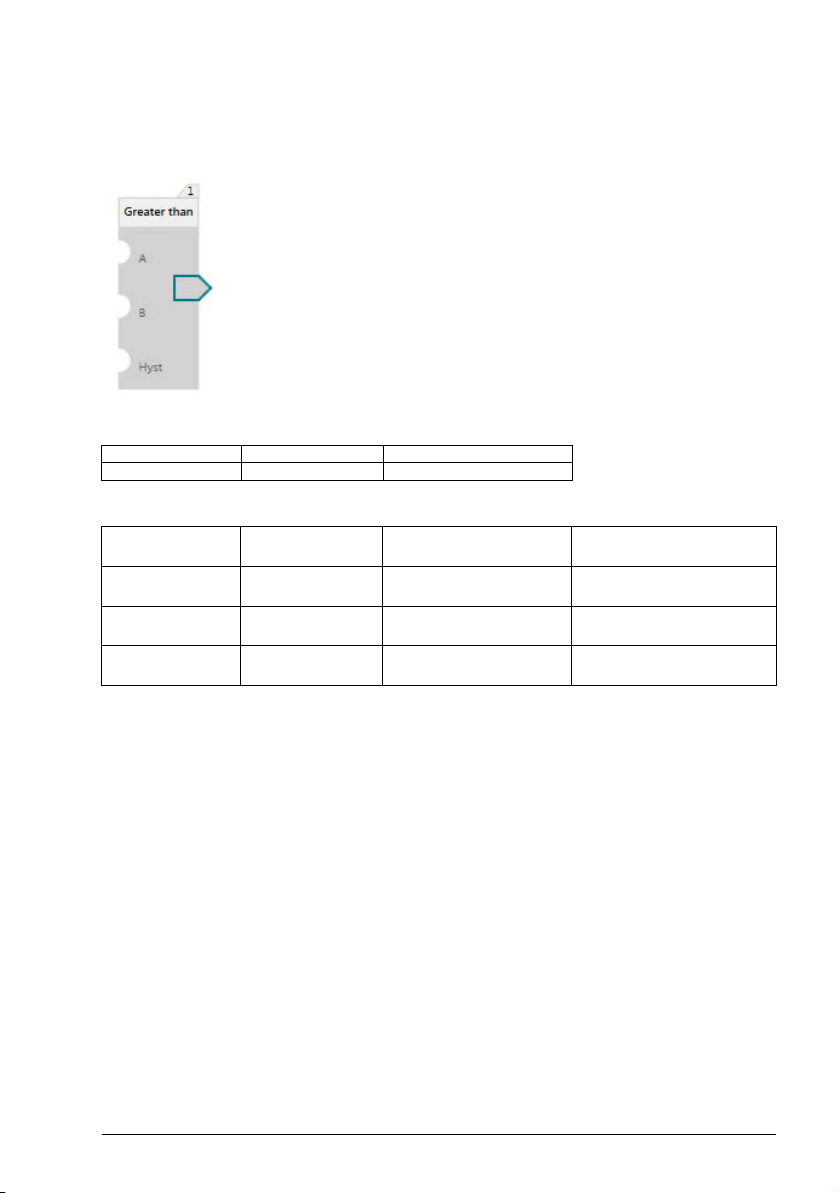
Greater than
Comparison block. Compares values at its inputs to see if first value is greater than
second. Comparison accuracy is set by the user.
Output
Name Type Default value
Out Boolean 0
Inputs: 3
Name Type Default value Function
A Float 0 Provides first
B Float 0 Provides second
Hyst Float 0 Value B is
Block function
comparison value
comparison value
subtracted
Takes two inputs to compare with one another, A and B, and a third input that
manipulates input B.
First:
• If A > B, output is set to 1.
Second (if first is not true):
• If A < (B- Hyst) then output is reset to 0.
Third (if neither are true):
• Previous output value is kept at block output.
Exceptional cases
• When either A or B input is not connected then output is set to default value 0.
• A disconnected Hyst input has value 0.
Page 48
48 Program elements
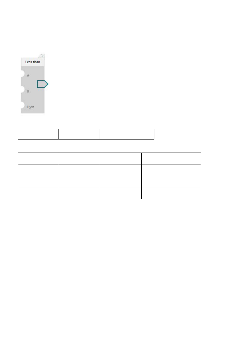
Less than
Comparison block. Compares values at its inputs to see if first value is smaller than
second. Comparison accuracy is set by the user.
Output
Name Type Default value
Out Boolean 0
Inputs: 3
Name Type Default
value
A Float 0 Provides first
B Float 0 Provides second
Hyst Float 0 Value that is added
Block function
Function
comparison value
comparison value
to B
Takes two inputs to compare with one another, A and B, and a third input that
manipulates input B.
First
• If A < B, output is set to 1.
Second (if first isn't true)
• If A > (B+ Hyst) then output is reset to 0.
Third (if neither are true)
• Previous output value is kept at block output.
Exceptional cases
• When either A or B input is not connected then output is set to default value 0.
• A disconnected Hyst input has value 0.
Page 49

Program elements 49
Limit
Takes an input that is limited and outputs the value after limiting it.
Output:
Name Type Default value
Out Float 0
Inputs: 3
Name Type Default value Function
In Float 0 Value to be limited.
Max Float 3.4028235e+38 Maximum value In is
Min Float - 3.4028235e+38 Minimum value In is
Block function
limited
limited.
In is written to the output as long as it is within the value range of Max and Min. When
In exceeds or falls below the respective limit values, it will first be capped to the
appropriate limit value and then written to the output. In is evaluated first against Max.
If Max is not limiting, then In is evaluated against Min.
Exceptional cases
•If In is not connected then the block output is zero.
•If Max or Min input is not connected, then the highest and lowest float values
are set as the default values for Max or Min.
Page 50
50 Program elements
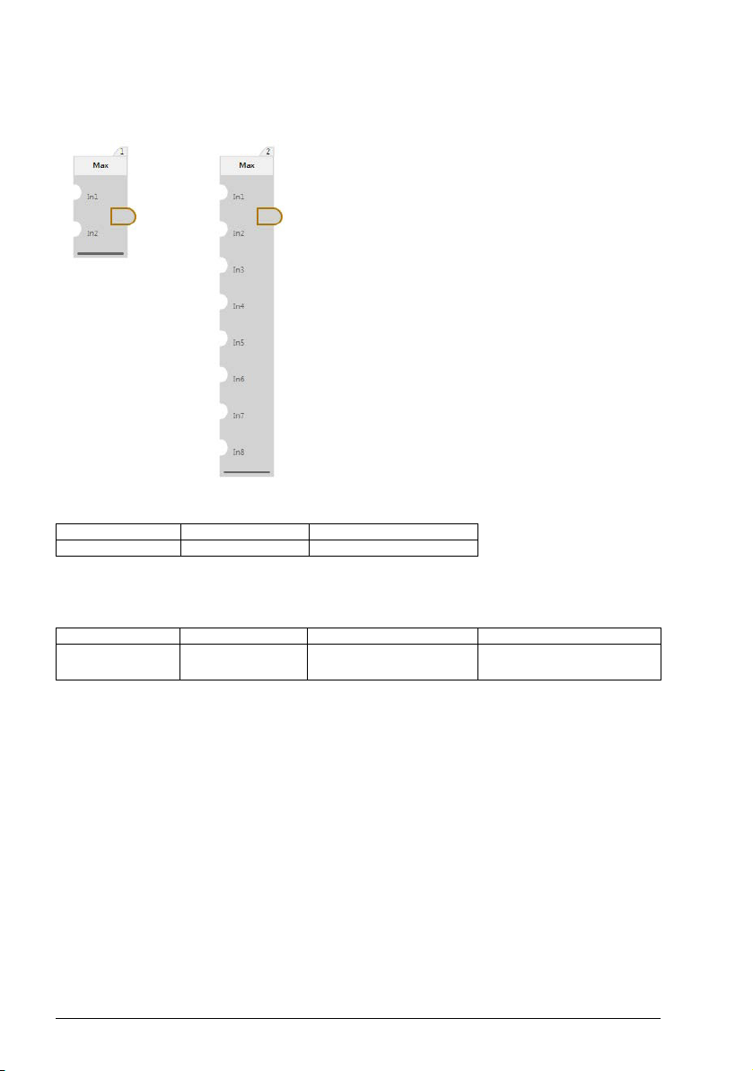
Max
Compares n inputs and outputs the largest input value.
Output:
Name Type Default value
Out Float 0
Inputs: 2-8
Default inputs: 2
Name Type Default value Function
In1 - In8 Float 0 Provides an input
value to compare
Block function
Compares all input values to determine the highest one and outputs it.
Exceptional cases
If some inputs are connected and other inputs are not connected, only the connected
inputs are evaluated.
Page 51
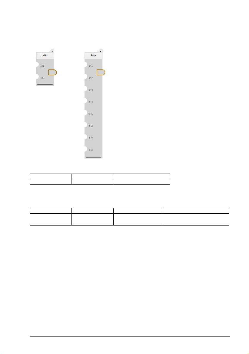
Min
Compares n inputs and outputs the smallest input value.
Output:
Name Type Default value
Out Float 0
Inputs: 2-8
Program elements 51
Default inputs: 2
Name Type Default value Function
In - In8 Float 0 Provides an input
value to be compared
Block function
Compares all input values to determine the lowest one and outputs it.
Exceptional cases
If some inputs are connected and others are not connected, only the connected
inputs are evaluated.
Page 52

52 Program elements
Multiply
Multiples n inputs and outputs the result.
Output:
Name Type Default value
Out Float 0
Inputs: 2-8
Default inputs: 2
Name Type Default value Function
In1 - In8 Float N/A Provides values for multiply
block to perform multiplication
Block function
Out = In1 * In2 *...* In8
Exceptional cases
• Inputs which are not connected are not multiplied. If one input is connected, its
value is at output.
• All inputs are not connected: output is assigned a default value.
• Overflow to positive side: output is limited to Max float.
• Overflow to the negative side: output is limited to negative Max float.
• Underflow: value 0 is kept at output.
Page 53

Program elements 53
NOT
Inverts value at input.
Output
Name Type Default value
Out Boolean 1
Input: 1
Name Type Default value Function
In Boolean 0 Block input
Block function
Function block performs inversion.
In Out
01
10
Exceptional cases
In case a block input is not connected then its value is set to 0 by default.
Page 54

54 Program elements
OR
Performs logic OR.
Output
Name Type Default value
Out Boolean 0
Inputs: 2-8
Default inputs: 2
Name Type Default value Function
In1 - In8 Boolean 0 Block inputs
Block function
Function block performs logical or operation with inputs. Out = In1 v In2 v … v In8.
The truth table of OR operation is below. Example uses two inputs. Same logic can
be applied to other inputs. Output has value 1 when one of the inputs have value 1.
Output is 0 if and all inputs have value 0.
In0 In1 Out
00 0
01 1
10 1
11 1
Exceptional cases
If some inputs are connected and others are not, only the connected inputs are
evaluated.
Page 55
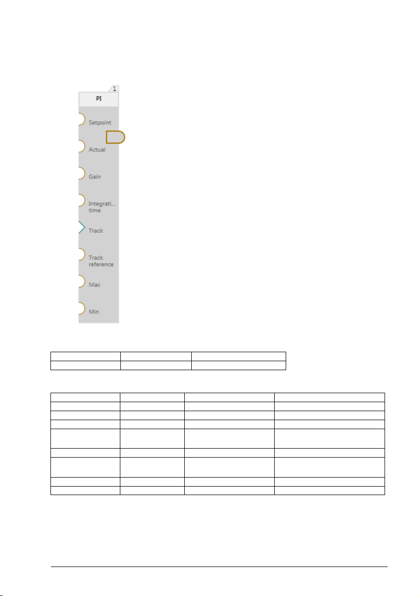
PI
PI controller.
Program elements 55
Output:
Name Type Default value
Out Float 0
Inputs: 8
Name Type Default value Function
Setpoint Float 0 Desired output value
Actual Float 0 Actual output value
Gain Float 0 Proportional gain (Kp)
Integration
time
Track Boolean 0 Enables tracking mode
Track
reference
Min Float - 3.4028235e+38 Maximum output value
Max Float 3.4028235e+38 Minimum output value
Float 0 Integration time in
seconds (s)
Float 0 Output value in
tracking mode
Page 56

56 Program elements
Block function
Calculates the P and I terms based on error, proportional gain and an integral
coefficient. The sum of P and I is written to the output. Sets output to tracking
reference value when tracking is enabled and limits the output when needed. In these
cases, the I term value is maintained directly in reference to the tracking reference or
limit values to provide smooth transfer/anti-windup. PI output continuous changing
from track reference value when track is disabled. In the limitation, the value is
evaluated first against Max limit. If Max is not limiting, then the value is evaluated
against Min limit.
Exceptional cases
• In case a block input is not connected then its value is set to default value.
• When either Setpoint, Actual or Gain are not connected then output is set to 0.
When Track is enabled and Track reference is not connected then output is
set to 0.
• When Integration time input is not connected then integral component is reset
and PI block functions as a P controller.
• When Min or Max is not connected, the default values of these inputs are
used.
Page 57

Program elements 57
Ramp
Changes the output value to match the input value at a defined rate of change.
Output:
Name Type Default value
Out Float 0
Inputs: 7
Name Type Default value Function
In Float 0 Reference value to
Increase Float 0 The amount of output
Decrease Float 0 The amount of output
Track Boolean 0 E nables tracking mode
Track
reference
Max Float 3.4028235e+38 Maximum value block
Min Float - 3.4028235e+38 Minimum value block
Float 0 Output value in tracking
ramp to output
increased per second
decreased per second
mode
output will be limited
output will be limited
Page 58

58 Program elements
Block function
If output value does not equal input reference, then the output value starts changing
towards the input value.
The amount of change per second is defined by the inputs for increasing and
decreasing the output. Sets output to track reference value when track is enabled.
Output is limited to maximum and minimum limit values. In the limitation, the output is
evaluated first against Max limit. If Max is not limiting, then the output is evaluated
against Min limit. Ramp output continues changing from tracking reference value
when tracking is disabled.
Exceptional cases
• In case a block input is not connected, then its value is set to default value.
• In case, either maximum or minimum limit is disconnected, then their values
will be defaulted to the highest and lowest value representable by a float.
• In case, Increase or Decrease input is disconnected then Output = In when
trying to ramp with the disconnected input. If the other input is connected then
ramping with it behaves as normal.
• In case, In input is disconnected then Output = 0.
Page 59

Program elements 59
Select boolean
Outputs the Boolean input value that is selected by the selector input.
Output
Name Type Default value
Out Boolean 0
Inputs: 3-9
Default inputs: 3
Name Type Default value Function
Sel Float 0 Selects input value to
In1 - In8 Boolean 0 Provides selectable input
connect to out put
value for the block.
Block function
This is a selector block that can have different input connected to output. Input to be
connected is selected by Sel input.
When Sel = 1 then Out = In1, when Sel = 2 Out = In2 etc.
When Sel = 8 Out = In8.
Allowable value range for Sel input is 1 <= Sel <= 8.
Exceptional cases
• When Sel input is out of its allowable range then Out = 0.
• Inputs which are not connected will have a default value.
Page 60
60 Program elements
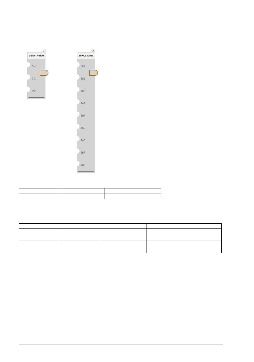
Select value
Outputs the float input value that is selected by the selector input.
Output
Name Type Default value
Out Float 0
Inputs: 3-9
Default inputs: 3
Name Type Default value Function
Sel Float 0 Selects input to be
In1 - In8 Float 0 Provides selectable input
connect to output
value for the block
Block function
This is a selector block that can have different input connected to output. Input to be
connected is selected by Sel input.
When, Sel = 1 then Out = In1, and Sel = 2 then Out = In2 and etc.
When, Sel = 8 then Out = In8.
Allowable value range for Sel input is 1 <= Sel <= 8.
Exceptional cases
• When Sel input is out of its allowable range then Output = 0.
• Inputs which are not connected will have a default value.
Page 61

Program elements 61
Set bits 0-7
Updates bits 0-7 of the input value.
Output
Name Type Default value
Out Float 0
Inputs: 9
Name Type Default value Function
In Float 0 Value to be updated
Bit0 Boolean N/A Value of bit 0 (lowest)
Bit1 Boolean N/A Value of bit 1
Bit2 Boolean N/A Value of bit 2
Bit3 Boolean N/A Value of bit 3
Bit4 Boolean N/A Value of bit 4
Bit5 Boolean N/A Value of bit 5
Bit6 Boolean N/A Value of bit 6
Bit7 Boolean N/A Value of bit 7
Block function
Rounds the float input to closest integer and updates bits 0-7 of the integer value
based on the boolean inputs Bit0-Bit7. Takes then the lowest 16 bits of the integer
result and converts the value to float and writes it to output.
Exceptional cases
• An input value that is either negative or larger than (2^31)-1 is set to default
value 0. Bits 0-7 of the default value are updated.
• If Boolean input is not connected, the value of that bit is not updated.
Page 62

62 Program elements
Set bits 8-15
Update bits 8-15 of the input value.
Output
Name Type Default value
Out Float 0
Inputs: 9
Name Type Default value Function
In Float 0 Value to be updated
Bit8 B oolean N/A Value of bit 8
Bit9 B oolean N/A Value of bit 9
Bit10 Boolean N/A Value of bit 10
Bit11 Boolean N/A Value of bit 11
Bit12 Boolean N/A Value of bit 12
Bit13 Boolean N/A Value of bit 13
Bit14 Boolean N/A Value of bit 14
Bit15 Boolean N/A Value of bit 15
Block function
Rounds the float input to closest integer and updates bits 8-15 of the integer value
based on the Boolean inputs Bit8-Bit15. Takes then the lowest 16 bits of the integer
result and converts the value to float and writes it to output.
Exceptional cases
• An input value that is either negative or larger than (2^31)-1 is set to default
value 0. Bits 8-15 of the default value are updated.
• If Boolean input is not connected, the value of that bit is not updated.
Page 63

Square root
Calculates square root of value at input.
Output
Name Type Default value
Out Float 0
Inputs: 1
Name Type Default value Function
In Float 0 Block input
Block function
Block calculates square root of input. Out =
Exceptional cases
• When value at the input is negative (In < 0), then Out = 0
Program elements 63
Page 64
64 Program elements
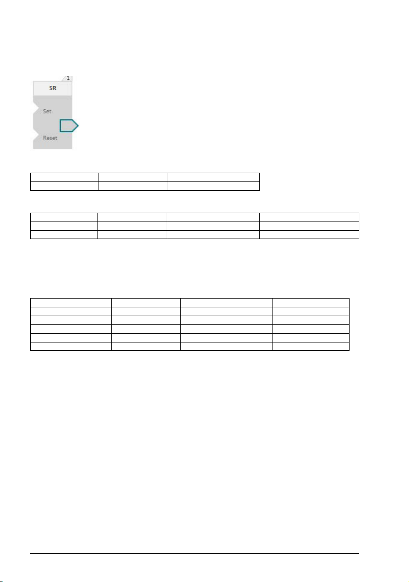
SR
SR trigger is used to store Set value.
Output
Name Type Default value
Out Boolean 0
Input: 2
Name Type Default value Function
Set Boolean 0 Set input
Reset Boolean 0 Reset
Block function
This is SR latch. Output keeps it value once set by Set input. Value at output is reset
to 0 when Reset = 1. Value at output depends on previous output value. See truth
table.
Previous Out Reset Set Current Out
000 0
001 1
x1x 0
100 1
101 1
Exceptional cases
•If Set is not connected, it is assumed to have default value.
•If Reset is not connected, it is assumed to have default value.
Page 65

Program elements 65
Subtract
Performs subtract.
Output:
Name Type Default value
Out Float 0
Inputs: 2
Name Type Default value Function
In1 Float 0 Value to subtract from
In2 Float 0 Value to be subtracted
Block function
Output = In1 - In2
Exceptional cases
• In case both inputs are not connected, output has a default value.
• Inputs which are not connected are assigned default value.
• Overflow to positive side: output is limited to Max float.
• Overflow to the negative side: output is limited to negative Max float.
• Underflow: value 0 is kept at output
Page 66
66 Program elements
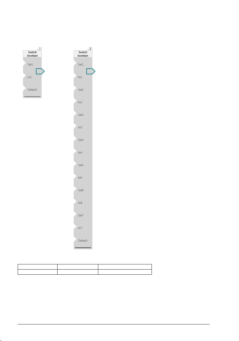
Switch boolean
Outputs the input Boolean value whose enable value is set first.
Output:
Name Type Default value
Out Boolean 0
Page 67

Program elements 67
Inputs: 3-15
Default inputs: 3
Name Type Default value Function
Sel1 - Sel7 Boolean 0 Selects/deselects input
In1 - In7 Boolean 0 Provides selectable input
Default Boolean 0 Default output when Sel
value.
value for the block.
is not active for any
inputs.
Block function
The value written to the output is “In X” value whose “Sel X” is set first. If no “Sel X” is
set then Default input is written to the output.
Example:
Multiple Sel inputs have value 1. Inputs are evaluated from top to bottom. In case of
multiple In, Sel pairs In1, Sel1 is checked first followed by In2, Sel2 and etc. In case
Multiple Sel inputs are 1 the first one will be connected to output. In this example, if
both Sel1 and Sel 2 are 1 then In1 is connected to output.
Exceptional cases
Inputs which are not connected will have a default value.
Page 68

68 Program elements
Switch value
Outputs the input float value whose enable value is set first.
Output:
Name Type Default value
Out Float 0
Page 69

Program elements 69
Inputs: 3-15
Default inputs: 3
Name Type Default value Function
Sel1 - Sel7 Boolean 0 Selects/deselects input
In1 - In7 Float 0 Provides selectable
Default Float 0 Default, that is,
value
input value for the block
connected to output
when no Sel is 1
Block function
The value written to the output is “In X” value whose “Sel X” is set first. If no “Sel X” is
set, then the Default input is written to the output.
Example:
Multiple Sel inputs have value 1. Inputs are evaluated from top to bottom. In case of
multiple In, Sel pairs In1, Sel1 is checked first followed by In2, Sel2 etc. In case
Multiple Sel inputs are 1, the first one will be connected to output. In this example, if
both Sel1 and Sel2 are 1 then In1 is connected to output.
Exceptional cases
• Inputs which are not connected will have a default value.
Page 70
70 Program elements
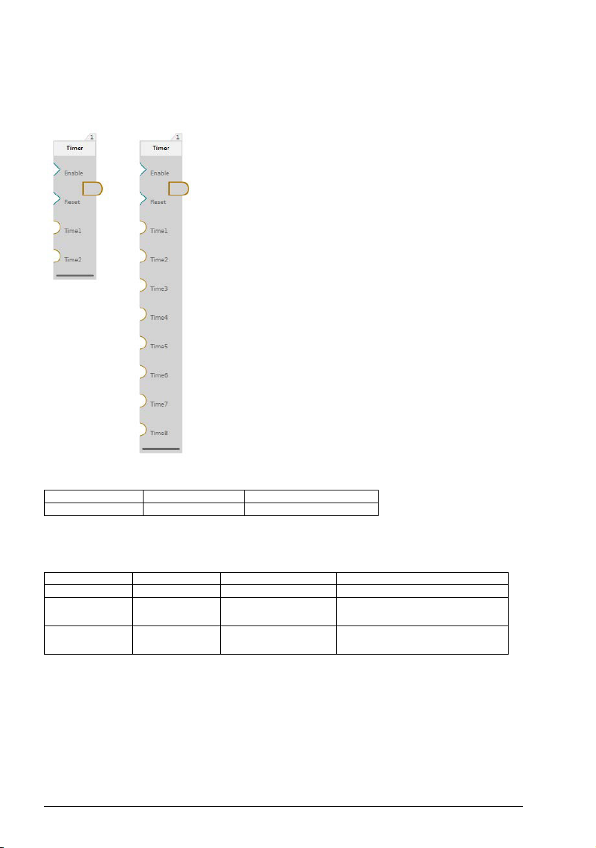
Timer
Runs through states at the speed of timer values defined at the inputs. Outputs the
current state. The timers can be paused and the state can be reset.
Output
Name Type Default value
Out Float 1
Inputs: 4-10
Default inputs: 4
Name Type Default value Function
Enable Boolean 0 Enables/disables timer.
Reset Boolean 0 Resets time when rising
Time1 Time8
Float 0 Provides time in state,
edge is detected on input.
time value is in seconds.
Page 71

Program elements 71
F
FFFFFF
T
T
TT
T
TT
112 33
1
1
1s 2s 3s 4s 5s 6s 7sTime, s
Reset
Enable
Out
F
FFFFFF
T
T
T
F
TT
112 223 3
1s 2s 3s 4s 5s 6s 7sTime, s
Reset
Enable
Out
F
Block function
Timer block is a state machine that goes through states. The time block stays in each
state is specified by time inputs Time1 - Time8. Minimal number of time inputs is 2.
When timer starts, it is in state 1 and block output is 1. Timer stays in this state for the
time specified in input Time1. When this time is passed, the timer block switches to
the next state. This behavior of normal operation is illustrated below. Reset is false,
enable is true. Time values Time1 = 2s, Time2 = 1s and Time3 = 2s are used in all
examples below.
Timer block can be paused by setting enable to false. During which the block stays in
the state that it was at the time. When Enable is set to true again, timer resume its
work from where it left off. The effect of enable input is illustrated below.
Timer block can be reset using the reset input. When rising edge is detected at the
reset input, block goes to state 1 if it is a valid state. If time in state 1 is specified to be
less than the time level that the program is running at, timer block will find the next
valid state to go to starting from state 1. If all states have delay times that are less
than the time level, block will go to state 1. The reset of the timer block happens also
in case the block is not enabled.
Page 72

72 Program elements
F
FF FF F F
T
T
T
F
TT
112 223 3
1s 2s 3s 4s 5s 6s 7sTime, s
Reset
Enable
Out
F
F
FFT TFF
T
T
T
T
TT
112 112 3
1s 2s 3s 4s 5s 6s 7sTime, s
Reset
Enable
Out
T
The reset behavior under normal circumstances is illustrated below. In this example
there are 3 time inputs and they all have valid delay times specified.
Block only reacts to rising edge. The reset behavior is illustrated below. The rising
edge occurs at time 4s. Reset input is left true but this does not interfere with block
operation. At time 5s block is in normal operation mode again.
Exceptional cases
• Not connected inputs get default values assigned.
• When specified time in a state is smaller than the value of the time level that the
program is running, the state will be skipped.
• When all time inputs have times specified that are smaller than the time level
value, the block output is set to default value.
Page 73

Program elements 73
Trigger down
Falling edge detection.
Output
Name Type Default value
Out Boolean 0
Input: 1
Name Type Default value Function
In Boolean 0 Block input
Block function
Function block performs falling edge detection. Output is 1 when input previous value
is 1 and current value is 0. Otherwise output is 0.
Exceptional cases
• If input In is not connected, it will get the default value.
• If input In has value 0 at the first execution cycle of the block, the output of the
block is set to 0.
Page 74

74 Program elements
Trigger up
Rising edge detection.
Output
Name Type Default value
Out Boolean 0
Input: 1
Name Type Default value Function
In Boolean 0 Block input
Block function
Function block performs rising edge detection. Output is 1 when block input previous
value is 0 and current value is 1. Otherwise output is 0.
Exceptional cases
• When input In is not connected, it will get the default value.
• If input In has value 1 at the first execution cycle of the block, the output of the
block is set to 1.
Page 75

Program elements 75
T_off
Turns off the delay.
Output
Name Type Default value
Out Boolean 0
Inputs: 2
Name Type Default value Function
In Boolean 0 Provides boolean value
Delay Float 0 Provides the time value in
seconds to delay outputting
0
Block function
If the value of In is 1 then it is written to the output. If the value of In is 0 it is written to
the output only after a time period is passed which is defined by Delay. Delay is
limited to 2097152 seconds.
Exceptional cases
In case a block input is not connected, then its value is set to default value.
Page 76

76 Program elements
T_on
Turns on the delay.
Output
Name Type Default value
Out Boolean 0
Inputs: 2
Name Type Default value Function
In Boolean 0 Provides boolean
Delay Float 0 Provides time value
Block function
If the value of In is 0 then it is written to the output. If the value of In is 1, it is written to
the output only after a time period is passed which is defined by Delay. Delay is
limited to 2097152 seconds.
Exceptional cases
value.
in seconds to delay
outputting 1.
In case a block input is not connected then its value is set to default value.
Page 77

Program elements 77
XOR
XOR inputs.
Output:
Name Type Default value
Out Boolean 0
Inputs: 2
Name Type Default value Function
In1 Boolean 0 Block input
In2 Boolean 0 Block input
Block function
Function block performs logical XOR operation with inputs.
The truth table of XOR operation:
In1 In2 Out
000
011
101
110
Output has value 1 when the inputs have different values, otherwise the output is 0.
Exceptional cases
In case a block input is not connected, the default value of the input is used in the
operation.
Page 78

78 Program elements
Page 79

Further information
Product and service inquiries
Address any inquiries about the product to your local ABB representative, quoting
the type designation and serial number of the unit in question. A listing of ABB sales,
support and service contacts can be found by navigating to
www.abb.com/searchchannels
Product training
For information on ABB product training, navigate to new.abb.com/service/training.
Providing feedback on ABB Drives manuals
Your comments on our manuals are welcome. Navigate to
new.abb.com/drives/manuals-feedback-form
Document library on the Internet
You can find manuals and other product documents in PDF format on the Internet at
www.abb.com/drives/documents
.
.
.
Page 80

Contact us
www.abb.com/drives
www.abb.com/drivespartners
3AXD50000028574 Rev C (EN) 2016-03-14
 Loading...