

ABB DPA Upscale RI 10, DPA Upscale RI 24, DPA Upscale RI 11, DPA Upscale RI 22, DPA Upscale RI 12 User Manual
...Page 1
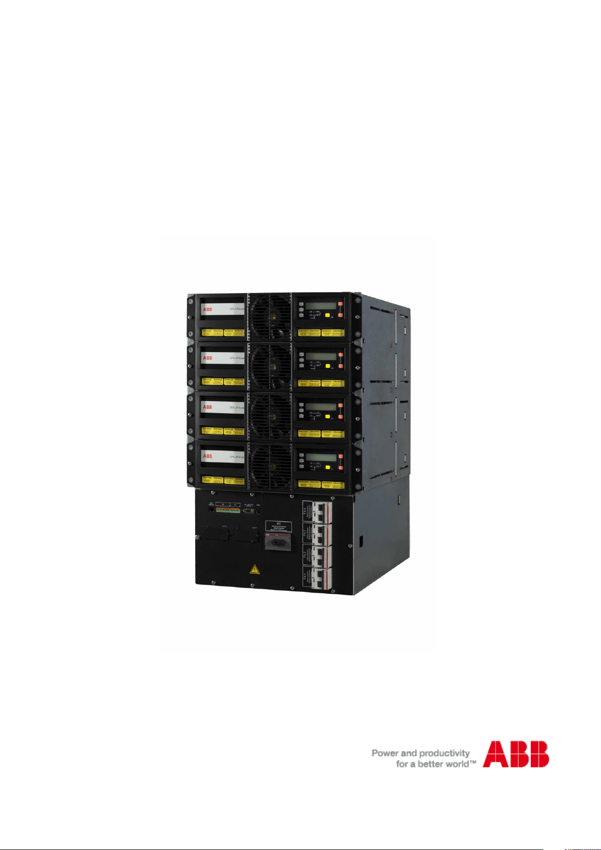
DPA UPSCALE
TM
RI 10 - 80 kW
User Manual
Edition 18.06.2012
© Copyright 2015 ABB, All rights reserved.
04-3006_S0_OPM_ABB_DPA_UPSCALE_RI_10-80kW_EN_150316.doc
Page 2

© Copyright ABB. All rights reserved.
Specification subjects to change
without notice.
Contact us
www.abb.com/ups
Section-0
04-3006_S0_OPM_ABB_DPA_UPSCALE_RI_10-80kW_EN_150316.doc Page 2/8 ABB
Modifications reserved
Page 3

GENERAL CONTENTS OF THE
Section-0
USER MANUAL DPA UPSCALE
TM
RI
0 SECTION-0:
0.1 FOREWORT
0.2 DPAUPSCALE RI SYSTEM DESCRIPTION
1 SECTION-1:
1.1 MECHANICAL CHARACTERISTICS DPA UPSCALE RI
1.2 SAFETY INSTRUCTIONS
1.2.1 GENERAL SAFETY INTRODUCTION
1.2.2 SYMBOLS, CONTROLS, AND INDICATORS
1.2.3 OPERATOR PRECAUTIONS
1.2.4 ENVIRONMENTAL CONSIDERATIONS
1.2.5 DECLARATION OF SAFETY CONFORMITY AND CE MARKING
1.2.6 INQUERIES
1.3 SYSTEM DESCRIPTION
1.3.1 GENERAL SYSTEM DESCRIPTION
1.3.2 DPA UPSCALE STTM BASIC SYSTEM CONFIGURATION
1.3.3 QUALITY STANDARDS AND UPS CLASSIFICATION CODE
1.3.4 SINGLE/PARALLEL-MODULES OPERATION
1.4 DELIVERY - TRANSPORT - STORAGE
1.4.1 INTRODUCTION
1.4.2 RECEIPT OF THE UPS AND VISUAL INSPECTION
1.4.3 UNPACKING
1.4.4 NAMEPLATE AND IDENTIFICATION
1.4.5 BATTERIES AND STORAGE
1.5 SITE PLANNING AND POSITIONING
1.5.1 PLANNING BEFORE THE INSTALLATION
1.5.2 POSITIONING OF UPS AND BATTERY CABINET
1.5.3 ASSEMBLING INSTRUCTION
1.6 ELECTRICAL INSTALLATION
1.6.1 PREPARATION FOR THE INPUT CABLING
1.6.2 INSTALLATION CHECKLIST
04-3006_S0_OPM_ABB_DPA_UPSCALE_RI_10-80kW_EN_150316.doc Page 3/8 ABB
Modifications reserved
Page 4

2 SECTION-2:
2.1 BLOCK DIAGRAM
2.1.1 WIRING AND BLOCK DIAGRAMS FOR ALL FRAMES AND MODULES
2.1.2 RECOMMENDED CABLE SECTIONS & FUSE RATINGS
2.1.3 BLOCK DIAGRAM DPA UPSCALE™
2.2 FRONT VIEW
2.2.1 FRONT VIEW OF DPA UPSCALE RI (RACK INDEPENDENT) ENCLOSURE
2.3 BATTERY CONNECTIONS
2.3.1 INTERNAL BATTERY MODULES
2.3.2 EXTERNAL BATTERY CABINET AND BATTERY CONNECTION
3 SECTION-3:
3.1 INTERFACING
3.1.1 CUSTOMER INTERFACE AND DRY PORTS (VOLT-FREE CONTACTS)
3.1.2 JD1 / RS232 COMPUTER INTERFACE
3.1.3 USB COMPUTER INTERFACE
Section-0
4 SECTION-4:
4.1 OPERATION
4.1.1 COMMISSIONING
4.1.2 CONTROL PANEL
4.1.3 DESCRIPTION OF THE LCD
4.1.4 OPERATING MODES
5 SECTION-5:
5.1 OPERATION–PROCEDURES
5.1.1 START-UP PROCEDURE
5.1.2 SHUTDOWN PROCEDURE
5.1.3 LOAD TRANSFER: FROM INVERTER OPERATION TO MAINTENANCE BYPASS
5.1.4 LOAD TRANSFER: FROM MAINTENANCE BYPASS TO INVERTER OPERATIONS
5.2 REPLACEMENT OF UPS-MODULE
5.2.1 REPLACEMENT OF UPS-MODULE IN SINGLE-MODULE SYSTEMS
5.2.2 REPLACEMENT OF UPS-MODULE IN REDUNDANT MULTI-MODULE SYSTEM
5.2.3 REPLACEMENT OF A MODULE IN CAPACITY MULTI-MODULE SYSTEM
04-3006_S0_OPM_ABB_DPA_UPSCALE_RI_10-80kW_EN_150316.doc Page 4/8 ABB
Modifications reserved
Page 5

6 SECTION-6:
6.1 MULTI-CABINET CONFIGURATION (NOT AVAILABLE)
7 SECTION-7:
7.1 MAINTENANCE
7.1.1 USER RESPONSIBILITIES
7.1.2 PREVENTATIVE MAINTENANCE
7.1.3 DEEP BATTERY TEST
7.1.4 BATTERY MAINTENANCE, DISPOSAL AND RECYCLING
8 SECTION-8:
8.1 TROUBLESHOOTING
8.1.1 ALARMS
8.1.2 MENU, COMMANDS, EVENT LOG, MEASUREMENTS,
8.1.3 FAULT IDENTIFICATION AND RECTIFICATION
Section-0
9 SECTION-9:
9.1 OPTIONS
9.1.1 INTRODUCTION
9.1.2 REMOTE SHUTDOWN (RSD)
9.1.3 GENERATOR ON FACILITIES (GEN ON)
9.1.4 WAVEMON SHUTDOWN AND MANAGEMENT SOFTWARE
9.1.5 SNMP CARD/ADAPTER FOR NETWORK MANAGEMENT /REMOTE MONITORING
04-3006_S0_OPM_ABB_DPA_UPSCALE_RI_10-80kW_EN_150316.doc Page 5/8 ABB
Modifications reserved
Page 6

10 SECTION-10: TECHNICAL DATA SHEET
10.1 DPA UPSCALE RI SYSTEM DESCRIPTION
10.2 TECHNICAL CHARACTERISTICS DPA UPSCALE RI
10.2.1 MECHANICAL CHARACTERISTICS DPA UPSCALE RI (RACK INDEPENDENT) SUBRACKS
10.3 INPUT CHARACTERISTICS
10.4 BATTERY CHARACTERISTICS
10.5 OUTPUT CHARACTERISTICS
10.5.1 GRAPH: AC – AC EFFICIENCY WITH LINIER LOAD @ COSPHI 1
10.5.2 GRAPH: OUTPUT POWER IN KW AND KVA VERSUS COSPHI
10.6 ENVIRONMENTAL CHARACTERISTICS
10.7 STANDARDS
10.8 COMMUNICATION
Section-0
10.8.1 POWER MANAGEMENT DISPLAY (PMD)
10.8.2 MIMIC DIAGRAM
10.8.3 DISPLAY
10.8.4 CUSTOMER INTERFACES TERMINALS X1…X2
10.8.5 CUSTOMER INPUTS DRY PORT S: TERMINAL BLOCK X2
10.8.6 CUSTOMER OUTPUTS DRY PORTS : TERMINAL BLOCKS X1
10.9 OPTIONS
10.9.1 SNMP CARD / WAVEMON MANAGEMENT SOFTWARE
10.10 BATTERY AUTONOMIES
10.10.1 EXAMPLES OF INTERNAL BATTERY AUTONOMY OF DPA UPSCALE RI 11, RI 12, RI 22, RI 24
10.11 INSTALLATION PLANNING
10.11.1 HEAT DISSIPATION PER MODULE WITH NON-LINEAR LOAD
10.12 WIRING AND BLOCK DIAGRAMS FOR ALL FRAMES AND MODULE
10.12.1 TERMINAL CONNECTIONS OVERVIEW
10.12.2 SINGLE FEED INPUT / CABLE SECTIONS
10.12.3 SINGLE FEED INPUT
10.12.4 DUAL FEED INPUT
10.12.5 DUAL FEED INPUT / CABLE SECTIONS
04-3006_S0_OPM_ABB_DPA_UPSCALE_RI_10-80kW_EN_150316.doc Page 6/8 ABB
Modifications reserved
Page 7

OPERATIONS INSIDE THE UPS MUST BE PERFORMED
BY A SERVICE ENGINEER FROM THE MANUFACTURER
OR FROM AN AGENT CERTIFIED BY THE
MANUFACTURER.
CAREFULLY READ THE USER MANUAL BEFORE
OPERATING OR WORKING ON THE UPS.
Section-0
0.1 FOREWORD
The UPS System operates with mains, battery or bypass power. It contains components that carry high
currents and voltages. The properly installed UPS System is grounded to earth and IP 20 rated against
electrical shock and foreign objects. Installation and service have to be done by the manufacturer’s
qualified technicians or their certified service partners.
This user manual contains guidelines to check delivery, installing and commissioning of the UPS and is
intended for people who plan the installation, install, commission and use or service the UPS. The
reader is expected to know the fundamentals of electricity, wiring, electrical components and electrical
schematic symbols
04-3006_S0_OPM_ABB_DPA_UPSCALE_RI_10-80kW_EN_150316.doc Page 7/8 ABB
Modifications reserved
Page 8

Section-0
0.2 DPA UPSCALE RI SYSTEM DESCRIPTION
In environments that demand zero downtime, continuous power protection availability is essential. In order to
respond to today’s dynamic IT and process-related environments that experience daily change through new server
technologies, migration and centralization, resilient and easily adaptable power protection concepts are required.
DPA UPScale is the foundation for continuous power protection availability of network-critical infrastructures in
enterprise data centers where business continuity has paramount importance and in process control environment
where manufacturing continuity is essential.
DPA UPScale’s is a third generation high-power-density (HPD), leading-edge double-conversion power protection
technology that has standardized on a modular component approach which helps speed deployment, improve
adaptability and increase system availability while reducing total cost of ownership.
DPA UPScale’s is a unique on-demand architecture that integrates the power rack, power distribution unit, back-up
battery rack and monitoring and management solutions to allow easy selection of optimized configurations.
DPA UPScale’s (Distributed Parallel Architecture) provides highest availability, unmatched flexibility and at the
same time lowest cost of ownership in IT environments.
This Technical Specification provides detailed technical information on the mechanical, electrical and
environmental performance of the DPA UPScale model types that can support to give answers to tender and enduser requirements. The DPA UPScale family was designed to respond to the most stringent safety, EMC and other
important UPS standards. DPA UPScale family is offered in two types of solutions:
DPA UPScale RI is a rack independent modular design offering 7-types of Rack Independent Subracks. Those can
accommodate DPA UPScale Rack based Modules for a wide range of power requirements:
DPA UPScale RI (rack independent) Subracks: DPA UPScale Modules types:
DPA UPScale RI 10 (20kW) UPScale M 10 (kW)
DPA UPScale RI 11 (20kW) UPScale M 20 (kW)
DPA UPScale RI 12 (20kW)
DPA UPScale RI 20 (40kW)
DPA UPScale RI 22 (40kW)
DPA UPScale RI 24 (40kW)
DPA UPScale RI 40 (80kW)
Key Features of DPA UPScale RI:
Highest Availability Near-zero down time
Modular, Decentralized Parallel Architecture (DPA)
High Power Density (up to 122kW / m2), Space-saving of expensive floor space
Small Footprint
Unity Output Power Factor No de-rating for loads with Unity PF
Full power for loads with unity PF
Highest Efficiency even with partial loads Energy cost saving during UPS-life-cycle
Efficiency = 94.5 - 95.5% for loads 25-100%
(depending on Module power and type of load)
Very low input current distortion THDi Gen-set power and installation cost saving
THDi = < 3@ 100 % load
04-3006_S0_OPM_ABB_DPA_UPSCALE_RI_10-80kW_EN_150316.doc Page 8/8 ABB
Modifications reserved
Page 9

CONTENTS SECTION-1
1.1 MECHANICAL CHARACTERISTICS DPA UPSCALE RI ................................................................. 2
1.2 SAFETY INSTRUCTIONS ................................................................................................................... 4
1.2.1 GENERAL SAFETY INTRODUCTION ........................................................................................ 4
1.2.2 SYMBOLS, CONTROLS, AND INDICATORS ............................................................................ 4
1.2.3 OPERATOR PRECAUTIONS ...................................................................................................... 5
1.2.4 ENVIRONMENTAL CONSIDERATIONS .................................................................................... 6
1.2.5 DECLARATION OF SAFETY CONFORMITY AND CE MARKING ............................................ 6
1.2.6 INQUIRIES ................................................................................................................................... 6
1.3 SYSTEM DESCRIPTION .................................................................................................................... 7
1.3.1 GENERAL SYSTEM DESCRIPTION .......................................................................................... 7
1.3.1.1 Feature : Unique “Safe-Swappable” Modules ..................................................................... 7
1.3.1.2 Feature : Advanced-Booster Technology ............................................................................ 7
1.3.1.3 Feature : Flexible Battery Management (FBM) ................................................................... 8
1.3.1.4 Feature : DPA Technology - Decentralized Parallel Architecture ....................................... 8
1.3.2 DPA UPSCALE™ RI BASIC SYSTEM CONFIGURATION ....................................................... 9
1.3.3 QUALITY STANDARDS AND UPS CLASSIFICATION CODE ................................................... 9
1.3.4 SINGLE/PARALLEL-MODULES OPERATION ......................................................................... 10
1.4 DELIVERY - TRANSPORT - STORAGE .......................................................................................... 11
1.4.1 INTRODUCTION ....................................................................................................................... 11
1.4.2 RECEIPT OF THE UPS AND VISUAL INSPECTION ............................................................... 11
1.4.3 UNPACKING .............................................................................................................................. 12
1.4.4 NAMEPLATE AND IDENTIFICATION ....................................................................................... 13
1.4.5 BATTERIES AND STORAGE .................................................................................................... 13
1.4.5.1 Storage of battery .............................................................................................................. 14
1.4.5.2 Storage of UPS .................................................................................................................. 14
1.5 SITE PLANNING AND POSITIONING ............................................................................................. 15
1.5.1 PLANNING BEFORE THE INSTALLATION .............................................................................. 15
1.5.2 POSITIONING OF UPS AND BATTERY CABINET .................................................................. 15
1.5.2.1 Final Transport ................................................................................................................... 15
1.5.2.2 Positioning ......................................................................................................................... 16
1.5.3 ASSEMBLING INSTRUCTIONS ............................................................................................... 17
1.5.3.1 Table of Weight .................................................................................................................. 17
1.5.3.2 Mechanical Drawing, Assembling and accessories DPA UPScale RI 10 ......................... 18
1.5.3.3 Mechanical Drawing, Assembling and accessories DPA UPScale RI 11 ......................... 22
1.5.3.4 Mechanical Drawing, Assembling and accessories DPA UPScale RI 12 ......................... 26
1.5.3.5 Mechanical Drawing, Assembling and accessories DPA UPScale RI 20 ......................... 30
1.5.3.6 Mechanical Drawing, Assembling and accessories DPA UPScale RI 22 ......................... 34
1.5.3.7 Mechanical Drawing, Assembling and accessories DPA UPScale RI 24 ......................... 38
1.5.3.8 Mechanical Drawing, Assembling and accessories DPA UPScale RI 40 ......................... 42
1.5.3.9 Air cooling flow DPA UPScale RI ....................................................................................... 46
1.6 ELECTRICAL INSTALLATION......................................................................................................... 48
1.6.1 PREPARATION FOR THE INPUT CABLING ........................................................................... 49
1.6.1.1 Mains supply and Earth connection ................................................................................... 49
1.6.1.2 Single Input Feed ............................................................................................................... 50
1.6.1.3 Dual Input Feed ................................................................................................................. 50
1.6.1.4 Preparation for the Output Cabling .................................................................................... 50
1.6.1.5 Connection of the Load ...................................................................................................... 51
1.6.2 INSTALLATION CHECKLIST .................................................................................................... 52
Section-1
04-3006_S1_OPM_ABB_DPA_UPSCALE_RI_10-80kW_EN_150316.doc Page 1/52 ABB
Modifications reserved
Page 10
DPA UPScale RI
unit
UPScale RI 10
UPScale RI 11
UPScale RI 12
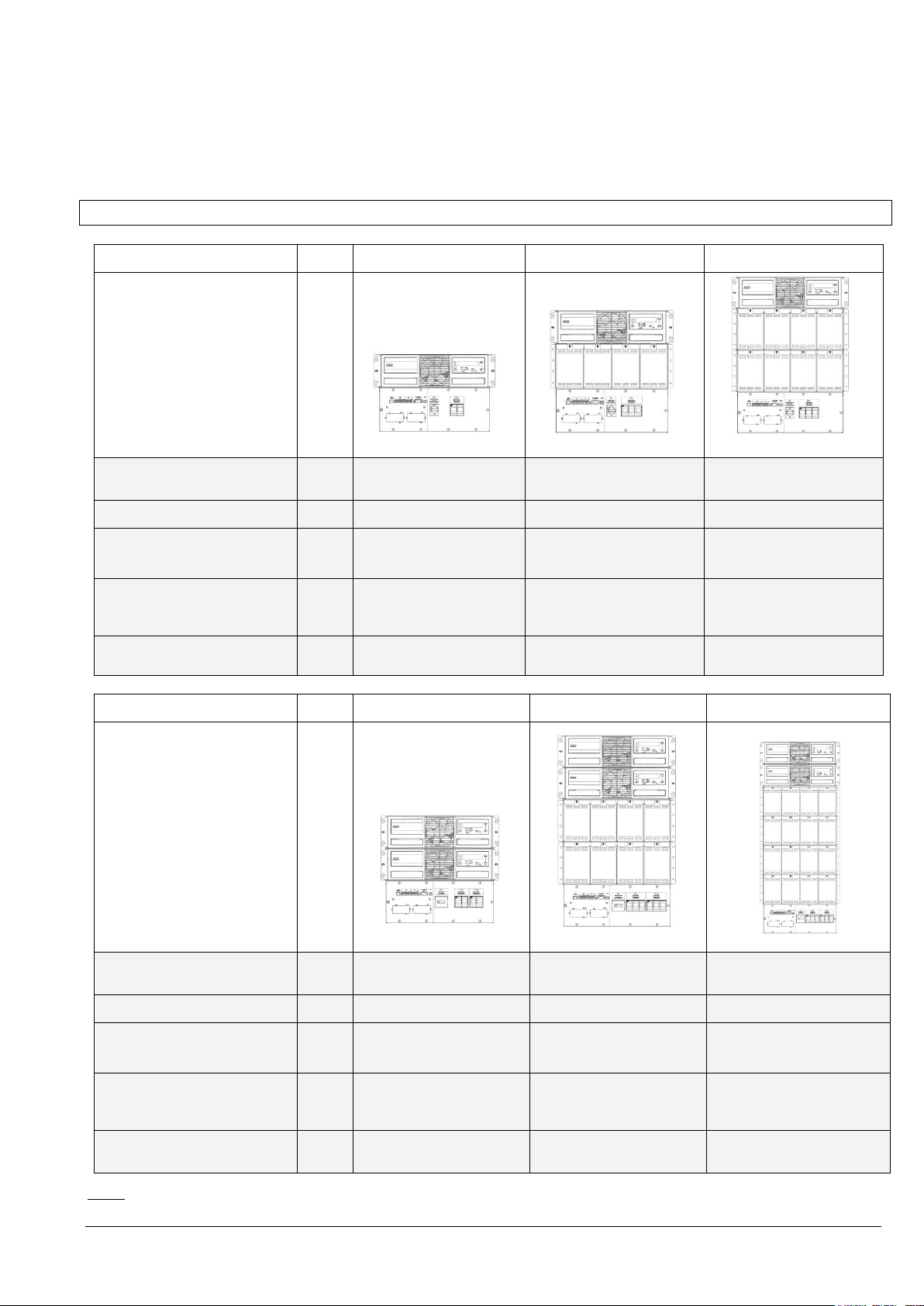
DPA UPScale RI Subrack
Configuration
accommodates:
Max.
1 module (10 or 20kW)
1 module (10 or 20kW)
with 40 x 7/9Ah batteries
1 module (10 or 20kW)
With 80 x 7/9Ah batteries
Max. Subrack connection
kW
20
20
20
Dimensions (WxHxD)
mm
448x310x565 (7 HU)
4821)x310x565 (7 HU)
448x487x735 (11 HU)
4821)x487x735 (11 HU)
448x665x735 (15 HU)
4821)x665x735 (15 HU)
Weight of Empty Frame
w/o modules and
w/o batteries
kg
20
40
56
Weight of Frame with
modules and w/o batteries
kg
39 up to 42
(with 1 Module)
59 up to 62
(with 1 Module)
75 up to 78
(with 1 Module)
DPA UPScale RI
unit
UPScale RI 20
UPScale RI 22
UPScale RI 24
DPA UPScale RI Subrack
Configuration
accommodates:
Max.
2 modules (10 or 20kW)
2 modules (10 or 20kW)
with 80 x 7/9Ah batteries
2 modules (10 or 20kW)
with 160 x 7/9Ah batteries
Max. Subrack connection
kW
40
40
40
Dimensions (WxHxD)
mm
448x440x565 (10 HU)
4821)x440x565(10 HU)
448x798x735 (18 HU)
4821)x798x735(18 HU)
448x1153x735 (26 HU)
4821)x1153x735(26 HU)
Weight of Empty Frame
w/o modules and
w/o batteries
kg
25
66
93
Weight of Frame with
modules and w/o batteries
kg
62 up to 68
(with 2 Modules)
103 up to 104
(with 2 Modules)
130 up to 136
(with 2 Modules)
1.1 MECHANICAL CHARACTERISTICS DPA UPSCALE RI
Section-1
Note : 1) 482 mm is the width including the wings in the front.
04-3006_S1_OPM_ABB_DPA_UPSCALE_RI_10-80kW_EN_150316.doc Page 2/52 ABB
Modifications reserved
Page 11
DPA UPScale RI
unit
UPScale RI 40
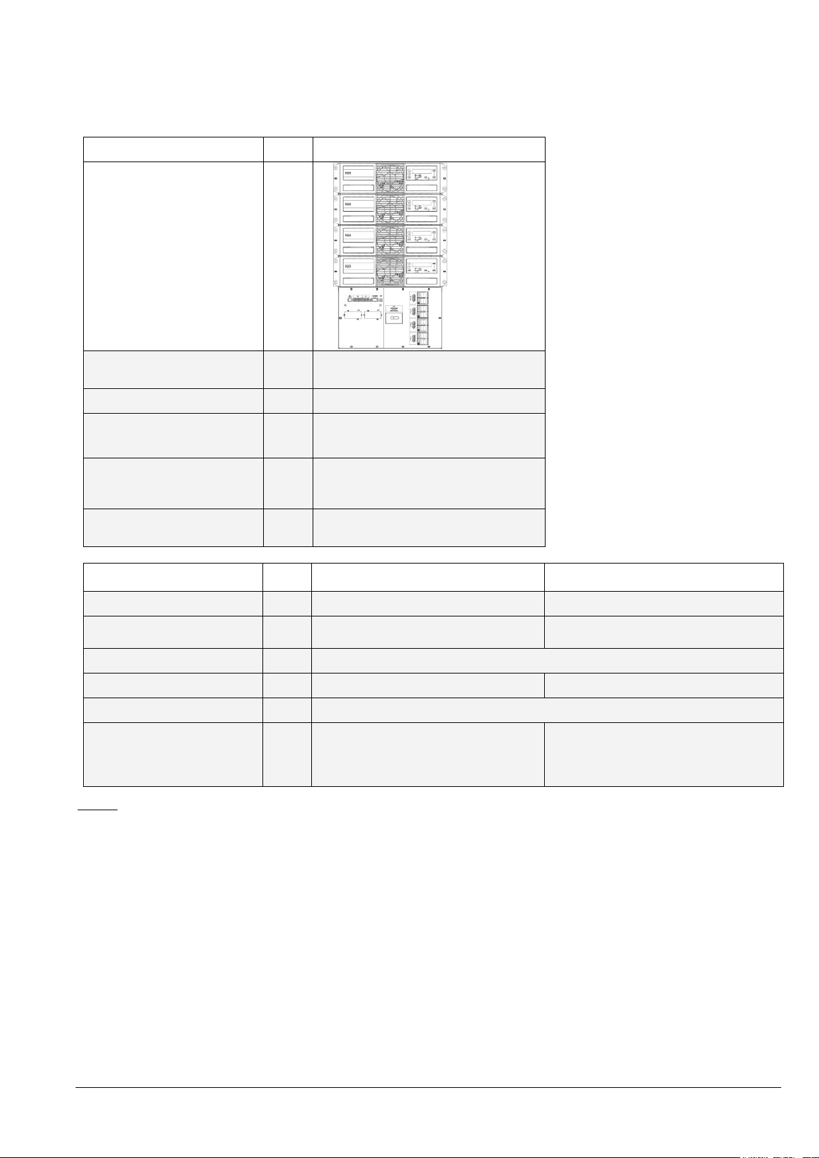
DPA UPScale RI Subrack
Configuration
accommodates:
Max.
4 modules (10 or 20kW)
Max. Subrack connection
kW
80
Dimensions (WxHxD)
mm
448x798x735 (18 HU)
4821)x798x735 (18 HU)
Weight of Empty Frame
w/o modules and
w/o batteries
kg
50
Weight of Frame with
modules and w/o batteries
kg
124 up to 136
(with 4 Modules)
Module type
unit
UPScale M 10
UPScale M 20
Module rated power
kW
10
20
Allowed nr. VRLA 12V
battery blocks
No.
202) - 50
302) - 50
Dimensions (WxHxD)
mm
4821) x 132 x 540 (3HU)
Weight
kg
18.6
21.5
Colors
Front : RAL 9005
Approximate3) audible
noise at 1m from front, of
one module only.
100% / 50% Load
dBA
553) / 493)
573) / 493)
Section-1
Notes:
1)
482 mm is the width including the wings in the front.
2)
Depending of the effective load in kW used by the module (see chapter 10.4 Battery Characteristics)
3)
These are approx. figures and of one module only. The audible noise depends also on the cabinet which host the
subracks.
04-3006_S1_OPM_ABB_DPA_UPSCALE_RI_10-80kW_EN_150316.doc Page 3/52 ABB
Modifications reserved
Page 12
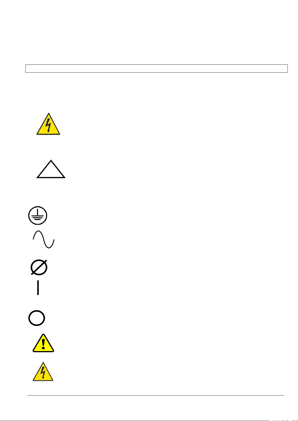
WARNING!
THERE IS DANGER OF AN ELECTRICAL IMPACT
NOTE!
READ THE INFORMATION, IN ORDER TO AVOID EQUIPMENT
DAMAGES
PROTECTIVE GROUNDING TERMINAL
A terminal which must be connected to earth ground prior to making any
other connection to the equipment.
A terminal to which or from which a direct current or voltage may be
applied or supplied.
This symbol indicates the word “phase”.
ON
The principal power switch is in the “ON” position
OFF
The principal power switch is in the “OFF” position.
C
St
CAUTION: REFER TO MANUAL
Refer to the Operator’s Manual for more information
DANGER: RISK OF ELECTRIC SHOCK
There is a risk of electric shock present, and you should observe
associated warnings. The UPS contains high voltages.
Section-1
1.2 SAFETY INSTRUCTIONS
1.2.1 GENERAL SAFETY INTRODUCTION
The UPS System operates with mains, battery or bypass power. It contains components that carry high currents
and voltages. The properly installed UPS System is grounded to earth and IP 20 rated against electrical shock and
foreign objects. Installation and service have to be done by the manufacturer’s qualified technicians or their certified
service partners.
This user manual contains guidelines to check delivery, installing and commissioning of the UPS and is intended
for people who plan the installation, install, commission and use or service the UPS. The reader is expected to
know the fundamentals of electricity, wiring, electrical components and electrical schematic symbols
1.2.2 SYMBOLS, CONTROLS, AND INDICATORS
04-3006_S1_OPM_ABB_DPA_UPSCALE_RI_10-80kW_EN_150316.doc Page 4/52 ABB
Modifications reserved
Page 13
WARNING!
IT IS PROHIBITED TO REMOVE ANY SCREWS FROM THE UPS SYSTEM OR
FROM THE BATTERY CABINET. THERE IS A DANGER OF ELECTRICAL SHOCK.
WARNING!
HIGH FAULT CURRENTS (LEAKAGE CURRENTS):
BEFORE CONNECTING THE MAINS YOU MUST ENSURE THAT THERE IS A
PROPER EARTH CONNECTION!
WARNING!
THE USER MUST DISPLAY A WARNING SHIELD ON ALL PRIMARY UPS
CIRCUIT BREAKERS. THE SERVICE PERSONNEL HAS TO BE INFORMED
ABOUT DANGEROUS VOLTAGES. THE WARNING PANELS MUST CONTAIN
THE FOLLOWING TEXT: “ BEFORE STARTING WITH THE MAINTENANCE
WORK ON THE CIRCUIT BREAKERS MAKE SURE THE UPS IS ISOLATED
Section-1
1.2.3 OPERATOR PRECAUTIONS
The only user operations permitted are:
Use of the LCD control panel (LCD Display) and of the Maintenance Bypass
Start up and shut down of the UPS of the user field (excluding the commissioning start up)
Operation of additional connectivity modules:
SNMP adapters and their software
Modem/GSM or Modem/Ethernet adapters and their software
The user must follow the precautions and only perform the described operations. Also in these measures the
operator of the UPS System must adhere to the instructions in this manual. Any deviations from the instructions
could be dangerous to the user or cause accidental load loss.
THE MANUFACTURER DOES NOT TAKE ANY RESPONSIBILITY FOR DAMAGES CAUSED THROUGH
WRONG MANIPULATIONS OF THE UPS SYSTEM.
04-3006_S1_OPM_ABB_DPA_UPSCALE_RI_10-80kW_EN_150316.doc Page 5/52 ABB
Modifications reserved
Page 14
Product Standards
Standards
Safety Standard:
IEC/EN 62040-1:
IEC/EN 60950-1:
Electromagnetic Compatibility
Standard (EMC):
IEC/EN 62040-2:
IEC/EN 61000-6-2:
IEC/EN 61000-6-4:
IEC/EN 61000-4-2:
IEC/EN 61000-4-3:
IEC/EN 61000-4-4:
IEC/EN 61000-4-5:
IEC/EN 61000-4-6:
Performance Standard:
IEC/EN 62040-3:
Section-1
1.2.4 ENVIRONMENTAL CONSIDERATIONS
The UPS must be installed according to the recommendations in this manual. To operate the UPS at peak
efficiency, your installation site should meet the environmental parameters outlined in this manual. Excessive
amount of dust in the operating environment of UPS may cause damage or lead to malfunction. The UPS should be
always protected from the outside weather and sunshine. If you intend to operate the system at an altitude higher
than 1000 meters, contact your local sales or service office for important information about high altitude operation.
The operating environment must meet the weight, airflow, size and clearance requirements specified in the
technical datasheet.
Under no circumstances the UPS should be installed in an airtight room, in the presence of flammable gases, or in
an environment exceeding the specification.
The basic environmental requirements of the UPS system are:
Ambient Temperature Range: 0 to +40˚C (32 – 104˚F)
Recommended Operating Range: +20 to +25˚C (68 – 77˚F)
Maximum Relative Humidity: 95% (non-condensing)
The UPS cabinet uses forced air cooling to regulate internal component temperature. Air inlets are in the bottom
sides and front of the cabinet, and outlets in the rear of the cabinet. You must allow clearance in back of the
cabinet for proper air circulation. Refer to
Section 1, 1.5.2.2 POSITIONING for clearance requirements.
1.2.5 DECLARATION OF SAFETY CONFORMITY AND CE MARKING
The product has the CE marking in compliance with the following European directives:
Low Voltage Directive: 2006/95/EC
EMC Directive: 2004/108/EC
Declaration of conformity with UPS harmonized standards and directives EN 62040-1-1 (Safety) and EN 62040-2
(EMC) are available in the annex 1
1.2.6 INQUIRIES
Address inquiries about the UPS and battery cabinet to the local office or agent certified by the manufacturer.
Please note the type code and the serial number of the equipment and contact your nearest agent certified by the
manufacturer.
The Code and the serial no. are shown on the nameplate see
04-3006_S1_OPM_ABB_DPA_UPSCALE_RI_10-80kW_EN_150316.doc Page 6/52 ABB
Section 1, 1.4.4 Nameplate and identification .
Modifications reserved
Page 15

Section-1
1.3 SYSTEM DESCRIPTION
The product described in this manual is a transformerless Uninterruptible Power System (UPS). It is a true online,
continuous duty, double conversion, solid state, three-phase system, providing conditioned and uninterruptible AC
power to protect the customer’s load from all nine power failures.
1.3.1 GENERAL SYSTEM DESCRIPTION
The UPS’s are used to protect sensitive equipment and prevent loss of valuable electronic information, minimise
equipment downtime, and minimise the adverse effect on production equipment due to unexpected power
problems.
The UPS system continually monitors incoming electrical power and removes the surges, spikes, sags, and other
irregularities that are inherent in commercial utility power. Working with a building‘s electrical system, the UPS
system supplies clean, consistent power that sensitive electronic equipment requires for reliable operation. During
brownouts, blackouts, and other power interruptions, batteries provide emergency power to safeguard operation.
The UPS system is housed in single freestanding cabinets. The cabinets line up and match in style and colour, and
have safety shields behind the doors for hazardous voltage protection.
1.3.1.1 Feature : Unique “Safe-Swappable” Modules
The unique Safe-Swappable feature of the Modules indicates the ability to insert and extract the electronic/power
modules from a larger assembly while it is powered (hot). The safe-swappable design allows live powered modules
to be attached to and removed from a powered set without causing disturbance to the operation of the load and
without need to go to bypass.
1.3.1.2 Feature : Advanced-Booster Technology
Traditional input THD filters are no longer needed with this UPS product. The build-in advanced booster technology
of UPS modules provides perfect sinusoidal input power quality at 0.99 input power factor with harmonic content
less than 3% THD(i). This leads to more reliable total system operation and savings in generator and transformer
sizing as losses in the windings are minimised.
Due to the active front booster, regulating each individual phase, the UPS is comparable to a clean resistor load
(unity) from the mains perspective. Thus, the high input power factor provides minimised cabling and fusing costs
due to no reactive power consumption. The low harmonic currents are due to high input power factor and provide
the benefits:
No additional losses in wires and cables
No extra heating of transformers and generators with shortened service life
No over sizing of generators
No false circuit breaker tripping and malfunction
No erratic operation of computers, telecommunication, monitors, electronic test equipment etc.
No Resonance with power factor correction capacitors
04-3006_S1_OPM_ABB_DPA_UPSCALE_RI_10-80kW_EN_150316.doc Page 7/52 ABB
Modifications reserved
Page 16

Section-1
1.3.1.3 Feature : Flexible Battery Management (FBM)
The Flexible Battery Management (FBM) has been designed in all UPS products with the goal to avoid the
deterioration of battery age. The FBM – Key Features protect the battery from environmental negative impacts (high
temperature and false manipulations) and avoid deterioration of battery life by advanced management of battery
charging and preventive failure diagnostics. The implemented features result in benefits not only for the end user,
but also to the environment. The battery user will be required to replace his batteries less often. This translates into
financial and environmental benefits. Last but not least a well protected and managed battery is a healthy battery
and hence it enhance the overall availability of the UPS system.
The major benefits are:
AC-Ripple free battery charging due to DC-DC charger separated from the rectifier and inverter
Wide range of number of battery blocks (20-50 blocks of 12V; depending autonomy times and power)
UPS’S wide input voltage window tolerance extends the battery life due to less discharge cycles
Battery discharge protection caused by load jumps
Proactive battery protection from false manipulations and inadequate charging voltages
Proactive battery failure detection thanks to Advanced Battery Diagnosis (ABD) - Algorithm
User selectable battery tests
Optional temperature compensated charging to enhance battery life
Hence, the function of FBM system is to prolong the battery life considerably compared to traditional systems. In a
traditional online UPS the inverter also causes ripple-current to be fed to batteries causing corrosion.
1.3.1.4 Feature : DPA Technology - Decentralized Parallel Architecture
The UPS product features DPA paralleling technology that provides N+X redundancy without introducing a singlepoint-of-failure. The products utilizing the DPA technology are completely autonomous be means of individual
Power Units, Bypasses, CPU’s, Control Panels and separate battery configuration for each single module.
The DPA technology makes it more reliable than traditional paralleling techniques. A parallel UPS system means
the linking together of two or more UPS units in parallel so that in the unlikely event one fails the other can
automatically take up the load. Traditionally a parallel redundancy configuration is achieved by having a random or
fixed master-slave relationship among the UPS units. This master logic gives out individual commands to all the
slaves units. Unfortunately this can lead to a single-point-of-failure for the whole system because if the master logic
or communication to slaves fails, and causes the whole UPS system to be in trouble.
The DPA technology was developed as a Multi-Master logic concept with separated independent regulation and
logic buses to allow parallel capacity system and to maintain the highest system availability. An industry leading
paralleling technology in its own right, the DPA technology enables you to set up a parallel redundant system giving
you 100% conditioned power at all times. Its unique decentralized design eliminates the system level single point of
failure inherent in traditional parallel UPS, and exponentially increases the reliability of the overall system.
DPA UPScale RI technology allows up to six UPS modules to cover the same load in parallel and redundant
configuration. No vulnerable master logic is needed in this design. It provides automatic load sharing and module
level redundancy with nothing other than the power connecting to the DPA UPScale RITM version of UPS modules.
04-3006_S1_OPM_ABB_DPA_UPSCALE_RI_10-80kW_EN_150316.doc Page 8/52 ABB
Modifications reserved
Page 17
DPA UPScale RI 10
DPA UPScale RI 11
DPA UPScale RI 12
DPA UPScale RI 20
DPA UPScale RI 22
DPA UPScale RI 24
DPA UPScale RI 40
Product Standards
Standards
Safety Standard:
IEC/EN 62040-1:
IEC/EN 60950-1:
Electromagnetic Compatibility
Standard (EMC):
IEC/EN 62040-2:
IEC/EN 61000-6-2:
IEC/EN 61000-6-4:
IEC/EN 61000-4-2:
IEC/EN 61000-4-3:
IEC/EN 61000-4-4:
IEC/EN 61000-4-5:
IEC/EN 61000-4-6:
Performance Standard:
IEC/EN 62040-3:
Section-1
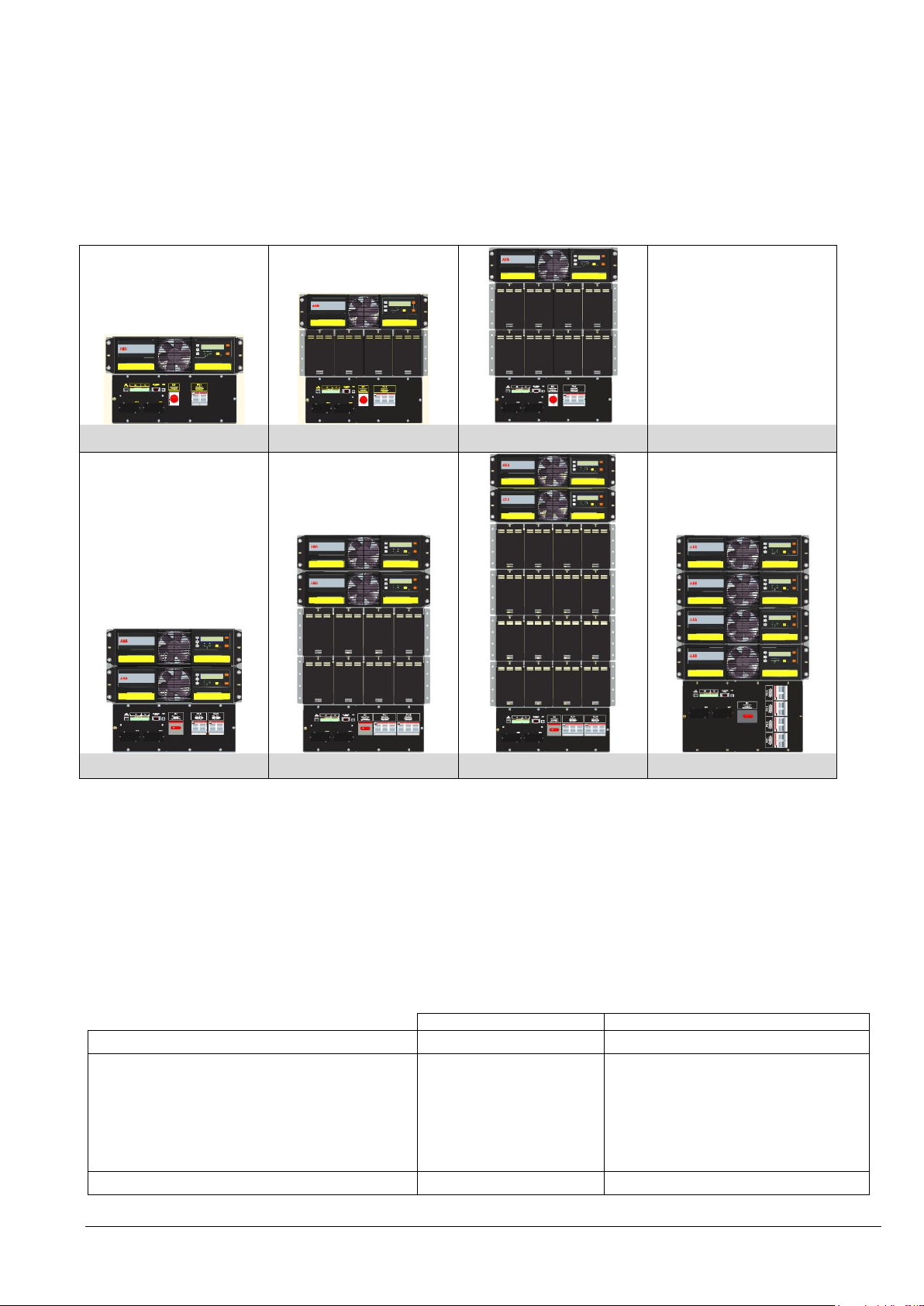
1.3.2 DPA UPSCALE™ RI BASIC SYSTEM CONFIGURATION
The UPS system can be housed in a rack independent cabinet of 19”. The following basic UPS systems
configurations are available:
1.3.3 QUALITY STANDARDS AND UPS CLASSIFICATION CODE
The DPA UPScaleTM will provide your critical equipment with a steady and reliable power supply for many
years.The unique and modular UPS DPA UPScaleTM belongs to the newest generation of midrange 3-phase UPSSystems. High reliability, low operating cost and excellent electrical performance are only some of the highlights of
this innovative UPS solution.
The criteria and methods implemented for the design and manufacture correspond to the most stringent quality
standards.
The manufacturer is certified successfully in every areas according to the model of the International Standard
ISO 9001/EN 29001. The Certification of UPS with the operating performance according to the Norm
IEC 62 040-3 and VDE 0558 Part 530 is accomplished. With it the UPS has the Classification Code VFl-SS-111.
04-3006_S1_OPM_ABB_DPA_UPSCALE_RI_10-80kW_EN_150316.doc Page 9/52 ABB
Modifications reserved
Page 18
Section-1
1.3.4 SINGLE/PARALLEL-MODULES OPERATION
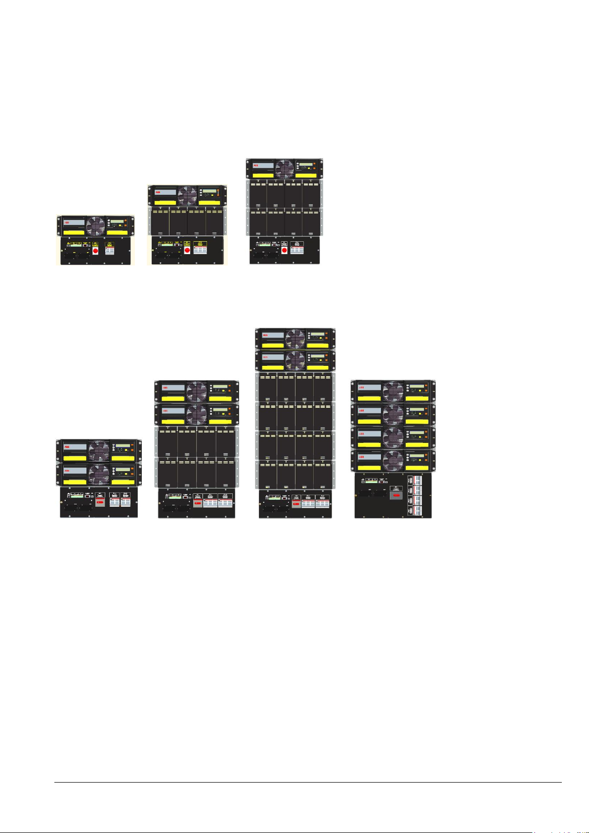
The DPA UPScaleTM has unique paralleling features. We distinguish: Single or Parallel-Modules
A) Single-Module
DPA UPScale RI 10 DPA UPScale RI 11 DPA UPScale RI 12
If a configuration consists of one single Module it is defined as a Single-Module Configuration even being in
different cabinets like UPScale RI-10 , UPScale RI-11, UPScale RI-12, with a single Module.
B) Parallel-Module:
DPA UPScale RI 20 DPA UPScale RI 22 DPA UPScale RI 24 DPA UPScale RI 40
A Parallel-Module is a Module that is operating in parallel with other equivalent Modules, but still within the same
cabinet (e.g. DPA UPScale RI 24) using the DPA technology
04-3006_S1_OPM_ABB_DPA_UPSCALE_RI_10-80kW_EN_150316.doc Page 10/52 ABB
Modifications reserved
Page 19
NOTE!
IF THE UPS IS NOT IMMEDIATELY INSTALLED THE FOLLOWING GUIDELINES
MUST BE FOLLOWED:
TRANSPORT:
UPS CABINETS AND/OR BATTERY CABINET CAN FALL OVER. USE THE
SHIPPING BRACKETS ON THE REAR AND FRONT TO SECURE THE
CABINETS. DO NOT TILT THEM MORE THAN 10° FROM VERTICAL,
OTHERWISE CABINETS MAY TIP OVER.
POTENTIAL DANGERS:
- TILTING THE CABINET MIGHT DAMAGE THE SYSTEM AND THEREFORE
SHOULD NO LONGER BE CONNECTED TO THE MAINS.
- WEIGHT OF THE UPS SYSTEM COULD CAUSE SERIOUS INJURIES TO
PERSONS OR ANYTHING IN THE SURROUNDING AREA.
STORAGE:
- THE UPS SHOULD BE STORED IN THE ORIGINAL PACKING AND
SHIPPING CARTON
- THE RECOMMENDED STORING TEMPERATURE FOR THE UPS SYSTEM
AND BATTERIES IS BETWEEN +20 °C AND +25°C.
- THE UPS SYSTEM AND THE BATTERIE SETS MUST BE PROTECTED FROM
HUMIDITY < 95% (NON-CONDENSING)
NOTE!
VISIBLE TRANSPORT DAMAGES MUST BE CLAIMED TO THE CARRIER
IMMEDIATELY AFTER RECEIPT !!
OTHER CLAIM FOR SHIPPING DAMAGE MUST BE FILED IMMEDIATELY TOO
AND THE CARRIER MUST BE INFORMED WITHIN 7 DAYS OF RECEIPT OF THE
EQUIPMENT. THE PACKING MATERIALS SHOULD BE STORED FOR FURTHER
INVESTIGATION.
Section-1
1.4 DELIVERY - TRANSPORT - STORAGE
1.4.1 INTRODUCTION
This chapter contains all the necessary information for the correct unpacking, positioning, cabling and installation of
the UPS.
The UPS and accessories are delivered on a specifically designed pallet that is easy to move with a forklift or a
pallet jack. Keep the UPS always in upright position and do not drop the equipment. Do not either stack the pallets
because of high-energy batteries involved and the heavy weight
1.4.2 RECEIPT OF THE UPS AND VISUAL INSPECTION
Upon receiving the UPS, carefully examine the packing container and the UPS for any sign of physical damage.
The outside ’Tip&Tel’ ( "FRAGILE" and "ARROW") indicator should be intact if the equipment has been transported
in the upright position. In case of rupture or suspect inform immediately:
Ensure that the received UPS corresponds to the material indicated in the delivery note.
The packing container of the UPS protects it from mechanical and environmental damage. To increase its
protection the UPS is wrapped with a plastic sheet.
04-3006_S1_OPM_ABB_DPA_UPSCALE_RI_10-80kW_EN_150316.doc Page 11/52 ABB
The carrier and
The manufacturer
Modifications reserved
Page 20
Bottom screws
Sides screws
!
KG
HEAVY !
3 1 1 2 4
Section-1
1.4.3 UNPACKING
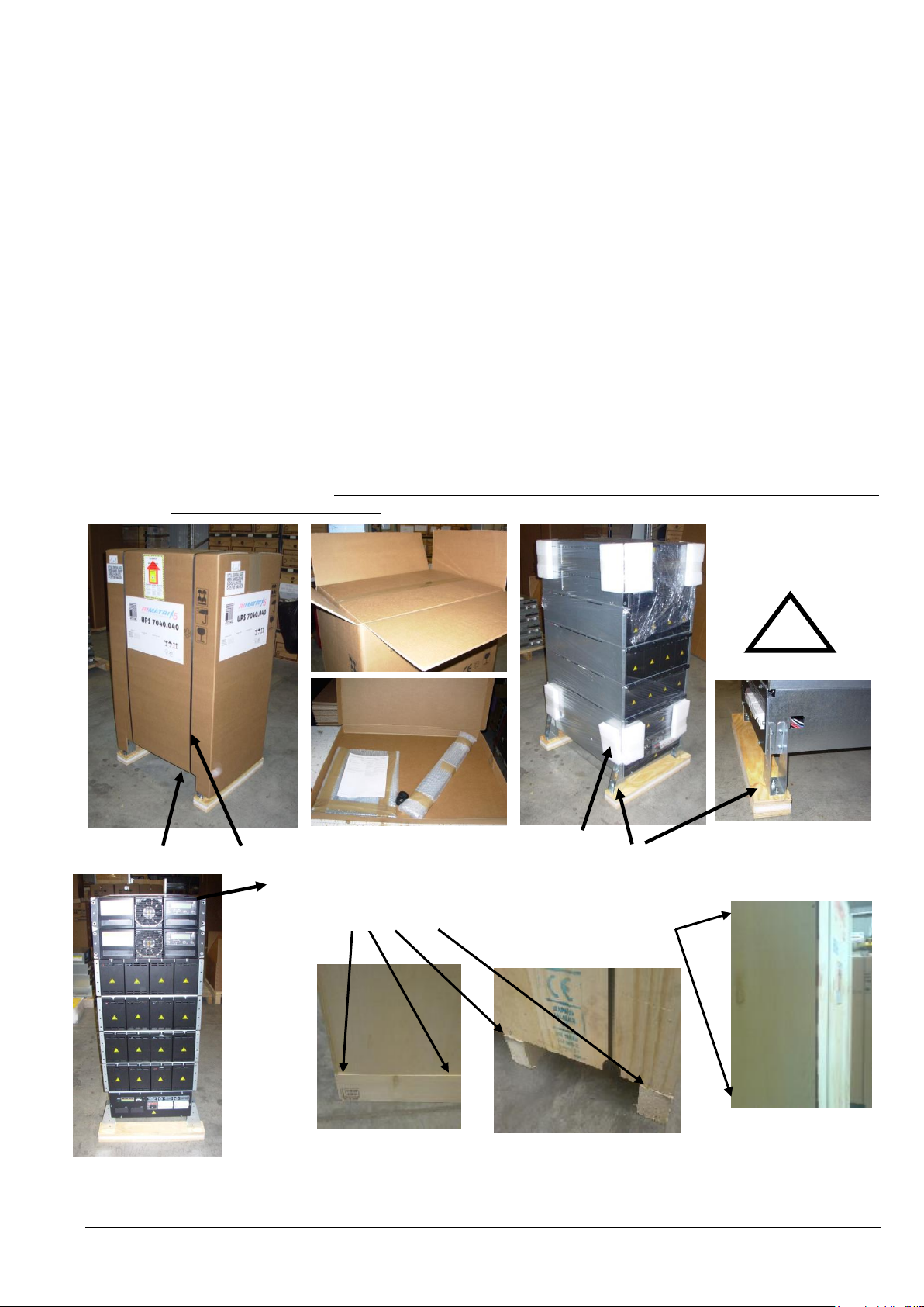
Unpack the equipment by removing the packing and shipping materials. Make a visual inspection and check that
’Tip&Tel’ indicator ( "FRAGILE" and "ARROW") on the packing container is intact.
Perform the following steps to unpack the UPS equipment from the pallet and make sure that the floor surface is
solid and suitable for the wheeling and heavy weight:
(1) Cut wrappers and remove packing container by pulling it upwards;
(2) Remove the plastic cover from the UPS;
(3) Remove pallet from the UPS;
Retain the packaging materials for future shipment of the UPS;
Examine the UPS for any sign of damage. Notify your carrier or supplier immediately if damage is
apparent.
(4a) Open the UPS-door and make sure that all the UPS-Modules are appropriately fitted in their UPS Compartment and if the UPS system is provided
(4b) Without a UPS-module make sure that the empty UPS-compartment is correctly covered with the UPS compartment protection cover.
By unpacking the equipment from the wooden case remove all screws.
04-3006_S1_OPM_ABB_DPA_UPSCALE_RI_10-80kW_EN_150316.doc Page 12/52 ABB
Modifications reserved
Page 21
TYPE
PRODUCT DESCRIPTION
DIMENSIONS
R1Uxxx
UPScale RI 10
Subrack (448x310x565mm)
R1Uxxx
UPScale RI 11
Subrack (448x487x735mm)
R1Uxxx
UPScale RI 12
Subrack (448x665x735mm)
R2Uxxx
UPScale RI 20
Subrack (448x440x565mm)
R2Uxxx
UPScale RI 22
Subrack (448x798x735mm)
R2Uxxx
UPScale RI 24
Subrack (448x1153x735mm)
R4Uxxx
UPScale RI 40
Subrack (448x798x735mm)
!
KG
HEAVY !
Section-1
1.4.4 NAMEPLATE AND IDENTIFICATION
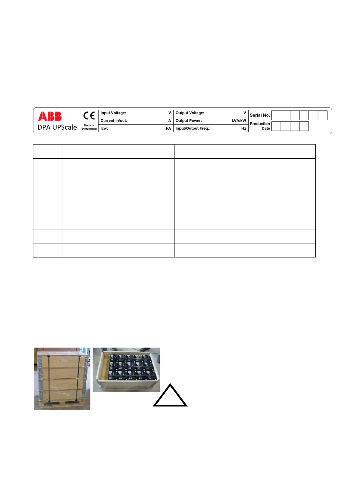
The technical specifications of the Equipment are provided on the nameplate, which is situated at the front of the
UPS. Check if it corresponds to the purchased material mentioned in the delivery note.
1.4.5 BATTERIES AND STORAGE
The standard batteries of the UPS are sealed, maintenance-free batteries, sometimes mounted in an external
battery cabinet and will typically be connected when the UPS is commissioned.
The battery life depends very much on the ambient temperature. A temperature range between +20° and +25°C will
achieve the optimum battery life.
If the UPS is delivered without batteries, the manufacturer is not responsible for any damage or malfunctioning
caused to the UPS by incorrect wiring.
04-3006_S1_OPM_ABB_DPA_UPSCALE_RI_10-80kW_EN_150316.doc Page 13/52 ABB
Modifications reserved
Page 22
WARNING!
SEALED BATTERIES MUST NEVER BE STORED IN A DISCHARGED OR
PARTIALLY DISCHARGED STATE.
EXTREME TEMPERATURE, UNDER- AND OVERCHARGE AND
OVERDISCHARGE WILL DESTROY BATTERIES!
NOTE!
THE UPS SYSTEM, THE BATTERY CABINET AND THE BATTERIES ARE HEAVY
AND MAY TIP DURING TRANSPORTATION CAUSING SERIOUS INJURY IF
UNPACKING INSTRUCTIONS ARE NOT CLOSELY FOLLOWED.
Section-1
1.4.5.1 Storage of battery
The battery life depends very much on the ambient temperature. It is therefore important to follow the storage
instructions/recommendation of the battery manufacturer. For long-term storage make sure that the battery is fully
recharged every 6 months. Before and after storing, charge the battery.
Always store the batteries in a dry, clean, cool environment in their original packaging. If the packing container is
removed protect the batteries from dust and humidity.
1.4.5.2 Storage of UPS
If you plan to store the UPS prior to use, keep the UPS unpacked in a dry, clean and cool storage room with an
ambient temperature between (-25 °C to +70°C) and humidity of less than 95% non-condensing.
If the packing container is removed protect the UPS from dust.
04-3006_S1_OPM_ABB_DPA_UPSCALE_RI_10-80kW_EN_150316.doc Page 14/52 ABB
Modifications reserved
Page 23
!
KG
HEAVY !
Section-1
1.5 SITE PLANNING AND POSITIONING
1.5.1 PLANNING BEFORE THE INSTALLATION
The equipment must be installed and transported in a upright position. The equipment requires space to
bottom/front and back to enable cooling airflow. It is required to arrange ventilation of the UPS room.
All parts of the UPS for service and user access are accessible from the front and rear, making it a service-friendly
and maintenance-friendly UPS. Reserve enough space from the front (min. 600 mm)
The UPS should be located where:
Humidity (< 95 % non-condensing) and temperature (+20° and +25°C ) are within prescribed limits
Fire protection standards are respected
Cabling can be performed easily
Available front accessibility for service or periodic maintenance
Requested air cooling flow should be granted
The air conditioning system should have sufficient amount of air cooling needed to keep the max. room
temperature rise at desired level:
Dust or corrosive/explosive gases must be absent
The place is vibration free
Only front access is necessary for service and maintenance.
If the UPS will be installed in bayed enclosures, partition walls have to be installed as well.
An ambient temperature of +20 to 25 Celsius degrees is recommended to achieve a long life of the UPS and
batteries. The cooling air entering the UPS must not exceed +40 °C. Avoid high ambient temperature, moisture and
humidity. The floor material should be non-flammable and strong enough to support the heavy load.
1.5.2 POSITIONING OF UPS AND BATTERY CABINET
1.5.2.1 Final Transport
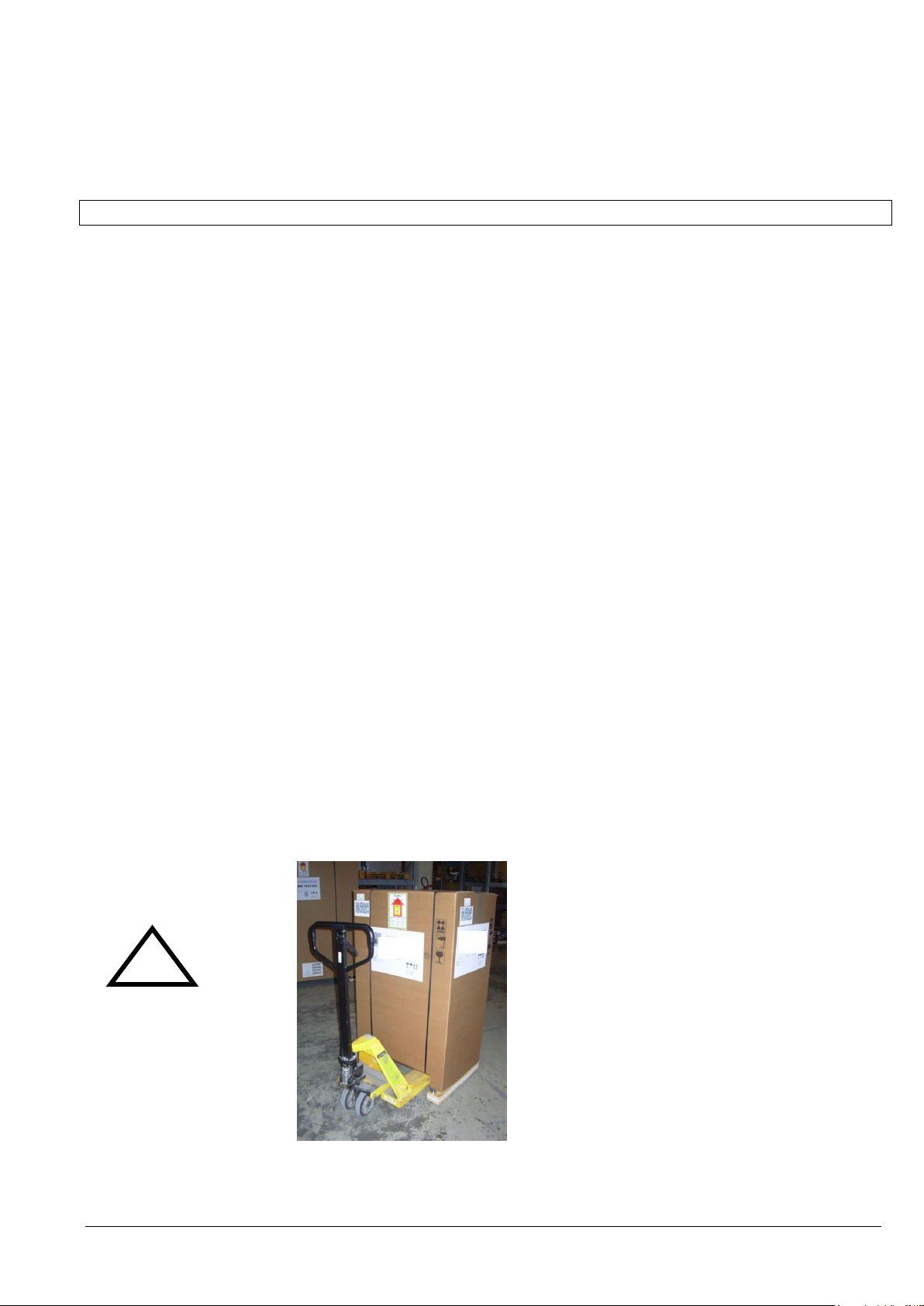
Check before transporting the surface loading and use a adequate forklift to move the equipment to the final
position.
Fig. 1.5.1 Floor surface must support loading
04-3006_S1_OPM_ABB_DPA_UPSCALE_RI_10-80kW_EN_150316.doc Page 15/52 ABB
Modifications reserved
Page 24
WARNING!
THE UPS CONTAINS HIGH DC VOLTAGES. A QUALIFIED PERSON MUST DO
THE CONNECTIONS BETWEEN THE UPS AND THE EXTERNAL BATTERY
CABINET(S). THE BATTERY CABINET IS CONNECTED ELECTRICALLY IN
PARALLEL WITH THE INTERNAL BATTERIES OF THE UPS.
WARNING!
IF AVAILABLE, THE INTERNAL BATTERY HAS TO BE DISCONNECTED
FIRST BECAUSE THE EXTERNAL
BATTERY TERMINALS ARE HAZARDOUS DUE TO THE PARALLEL
BATTERY STRING.
Section-1
1.5.2.2 Positioning
UPS: DPA UPScale RI is a rack independent design which is always mounted into a rack. The hosting rack must
have front and back opening for that air flow. The cold or ambient temp. air inlet is on the front; the hot air outlet is
on the back. Back clearance of min. 20 cm is required for hot air outlet.
External Battery: If external battery are needed it’s recommended to install external battery cabinet(s) next to the
UPS unit. The external battery can be placed on either side of the UPS unit, but it is recommended to install on left
hand side. External battery racks shall be sized to take the voltage drop in the cable into account. To obtain
support and help contact the local office or agent certified by the manufacturer.
Check before the installation that the battery voltage values in the ID card or in the Display settings of the UPS and
external battery cabinets are the same.
04-3006_S1_OPM_ABB_DPA_UPSCALE_RI_10-80kW_EN_150316.doc Page 16/52 ABB
Modifications reserved
Page 25

Subrack type
RI 10
RI 11
RI 12
RI 20
RI 22
RI 24
RI 40
Accessibility
Totally front accessibility for service and maintenance
Clearances
Back clearance of min. 20 cm required for hot air outlet. Cold air inlet is from front.
Positioning and mounting
see operating manual, Section 1 for details and mounting instructions.
Input and Output Cabling
From the bottom on the rear side.
UPScale RI
max. configuration
RI 10
RI 11
RI 12
RI 20
RI 22
RI 24
RI 40
Weight of empty frame
w/o modules and
w/o batteries
kg
20
40
56
25
66
93
50
Weight of empty frame
with modules and
w/o batteries
kg
39 - 42
59 - 62
75 - 78
44 - 47
104 -
110
131 -
137
124 -
136
Weight of empty frame
with modules and
with all batteries
kg
-
161 - 164
279 -
282
--
308 -
314
539 -
545
-
12V 7Ah battery block
2.5 kg
12V 9Ah battery block
2.55kg
UPS module M10
18.6 kg
UPS module M20
21.5 kg
1.5.3 ASSEMBLING INSTRUCTIONS
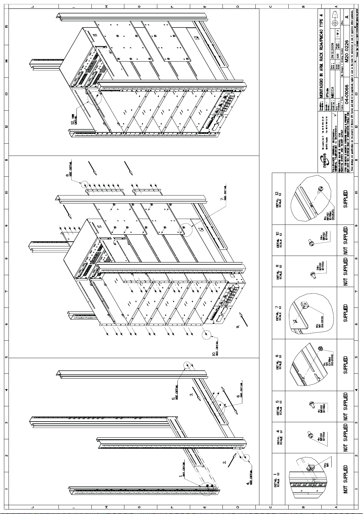
Please make sure that the 19” Rack has a structure with minimum structure with four post system (see fig.
2.1 -2.7)
Please make sure that the four post system can hold the weight of the total UPS system. Refer to the table
below.
Position and air cooling flow at the 19” Rack. Please refer to the figures 4.1 and 4.2 to make sure the
required airflow and the right position is used.
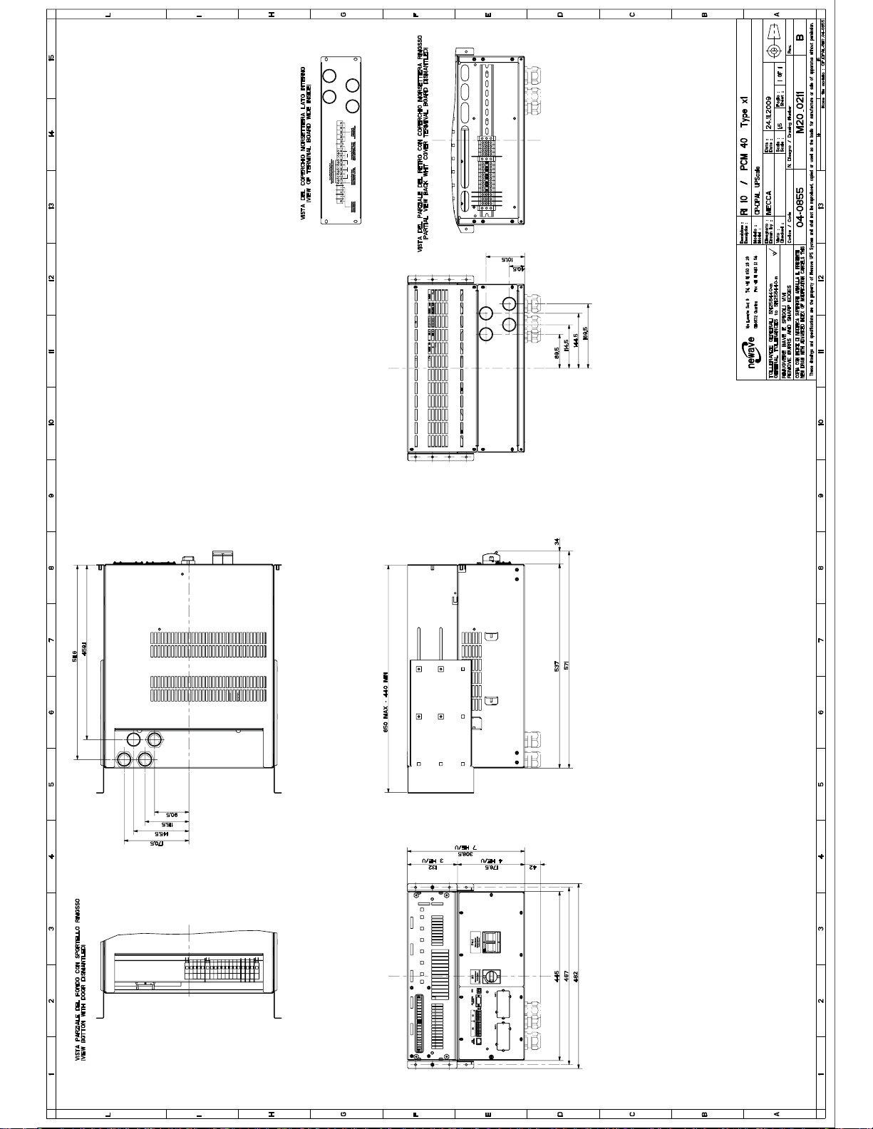
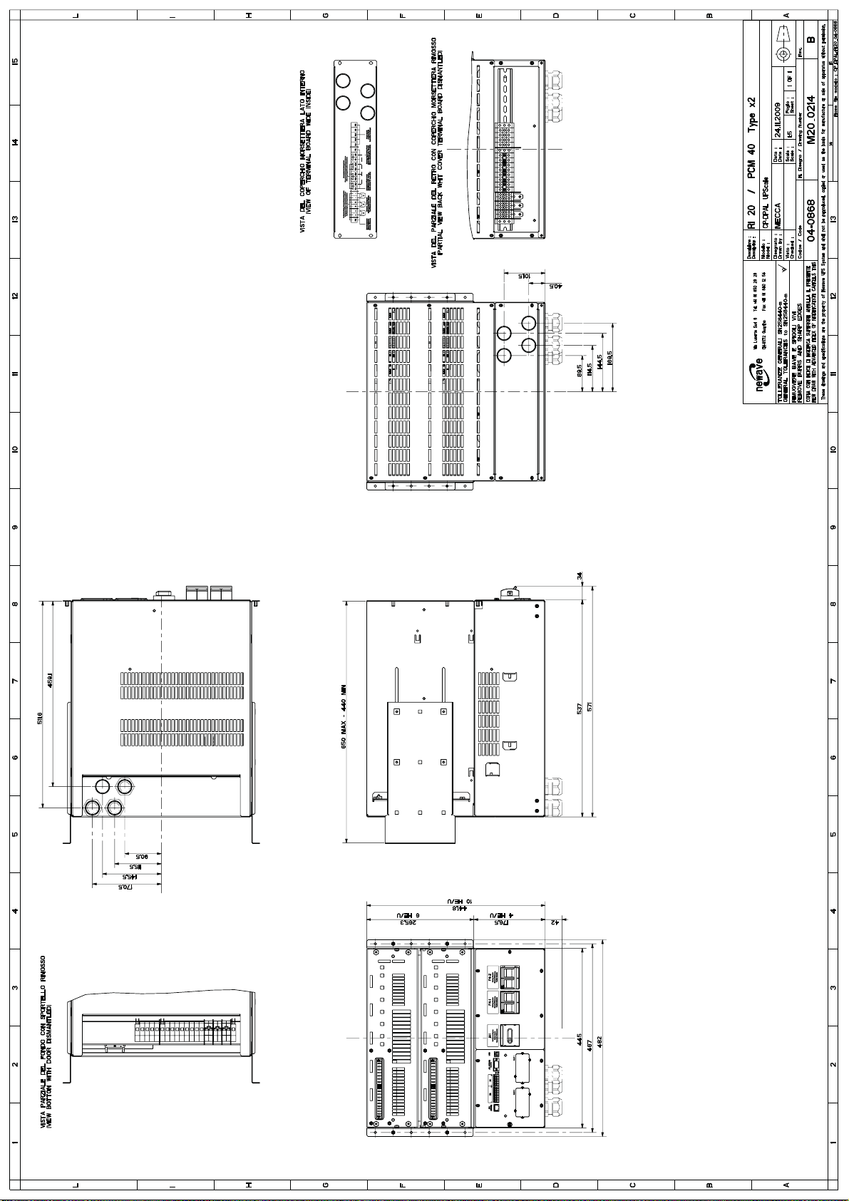
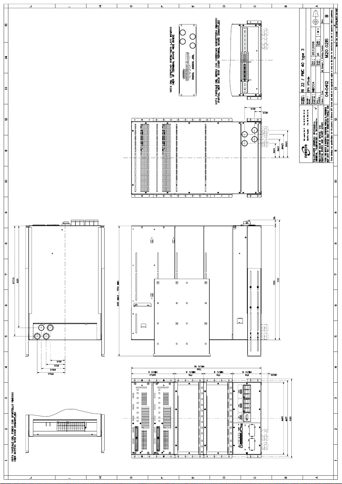
The dimensions of the sub rack are shown in fig 1.1 – fig. 1.7
The terminal for input and output connection is at the rear side of the sub rack. The cable entry can be
made from rear or from bottom side. (see fig. 1.1 – 1.7)
For mounting the sub rack into your mains rack, you have to remove all the ups modules and the battery
treys from the sub rack.
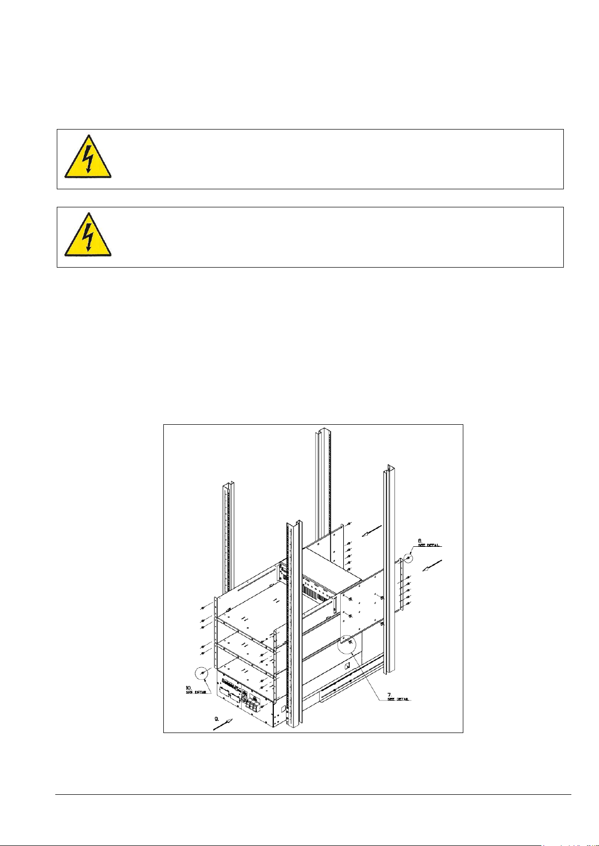
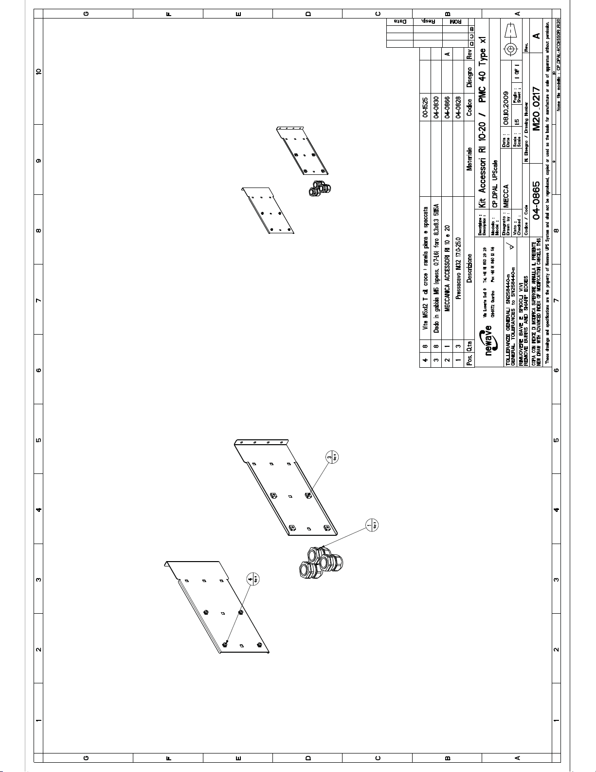
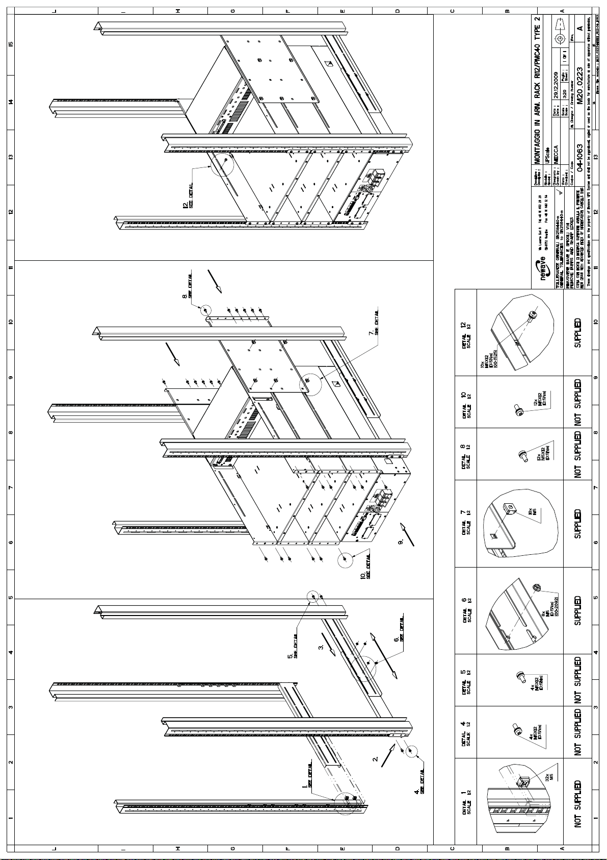
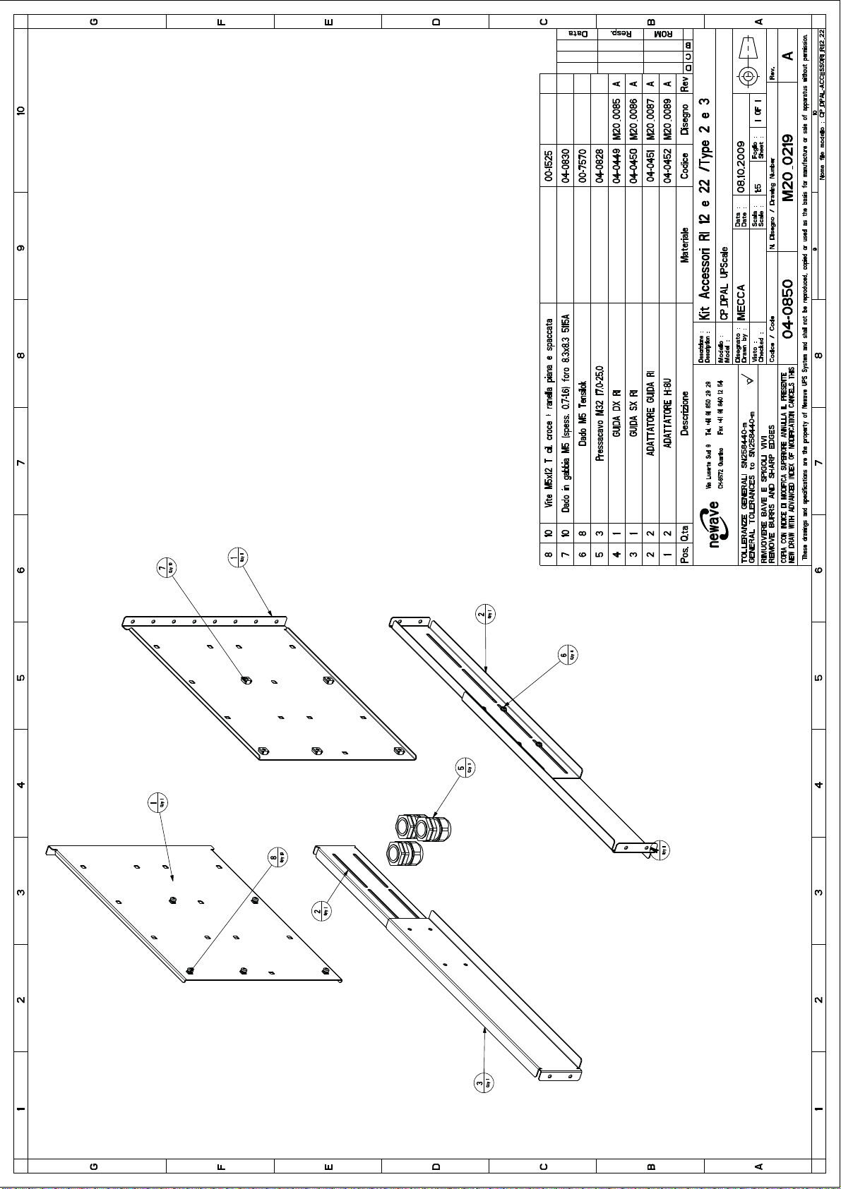
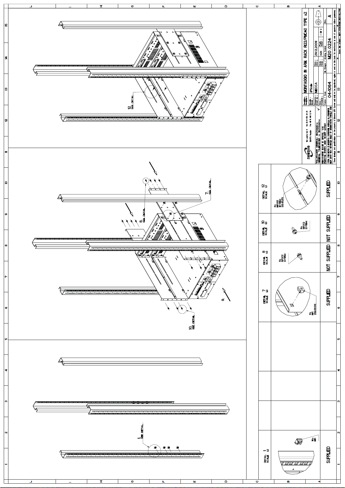
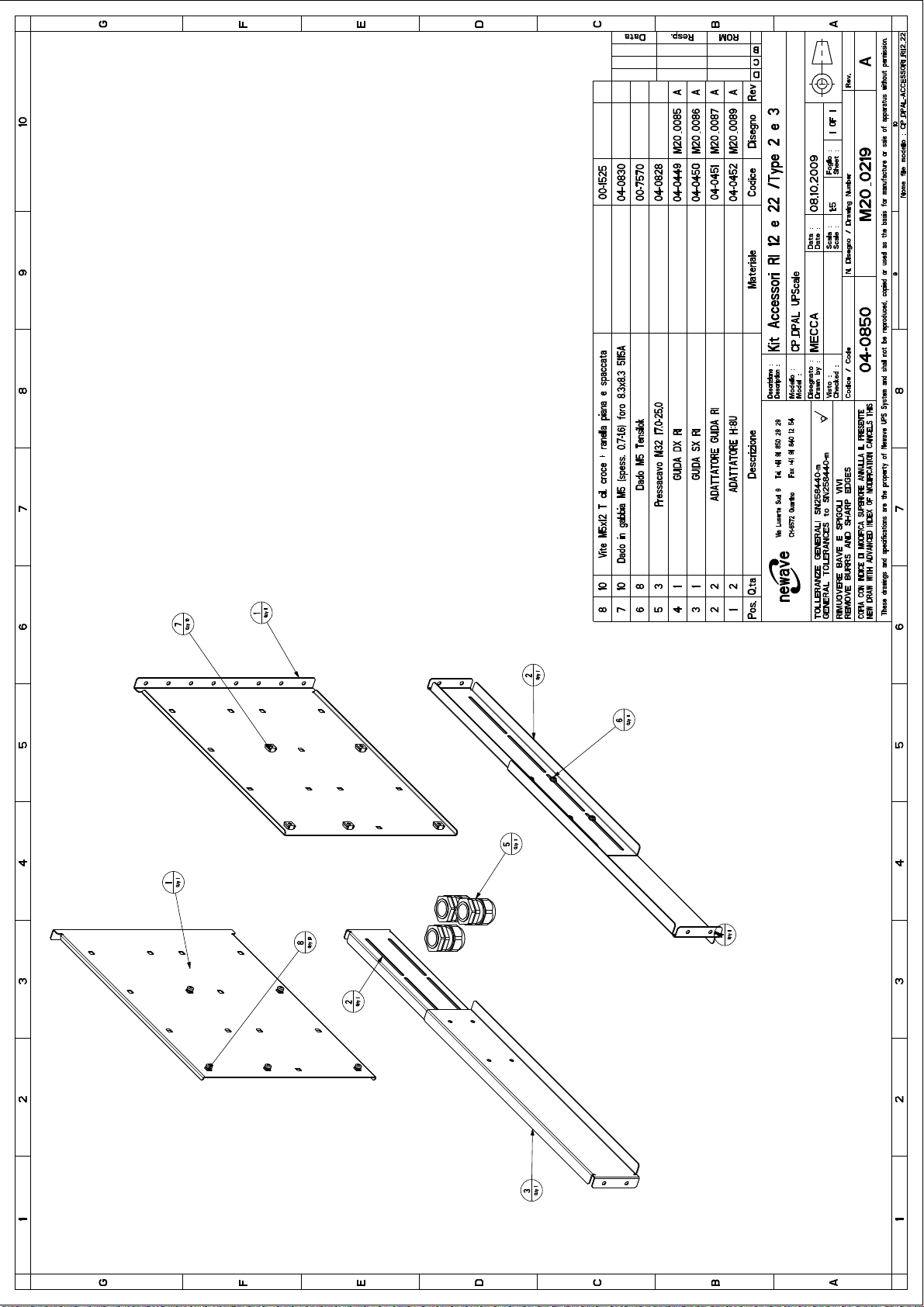
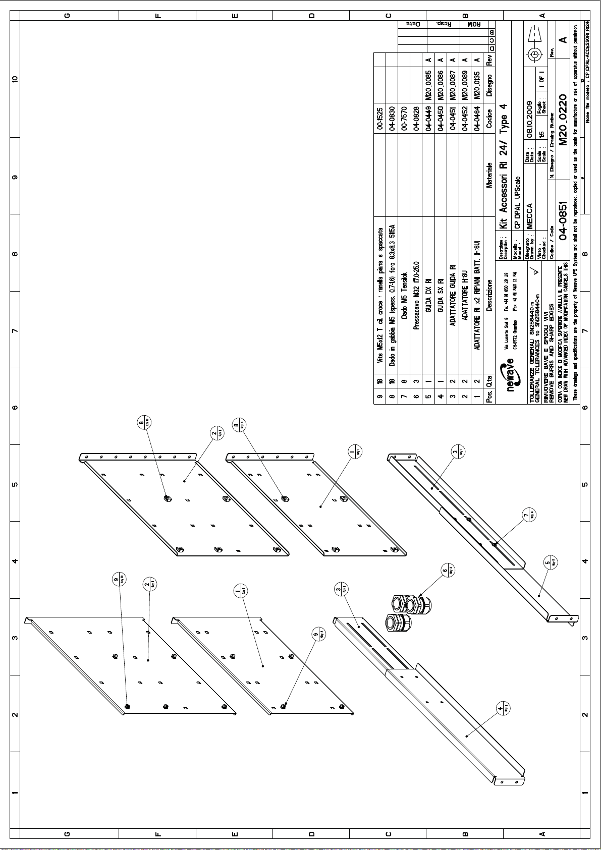
Please use only the slides and brackets from the delivered accessories kit (see fig. 3.1 – 3.5)
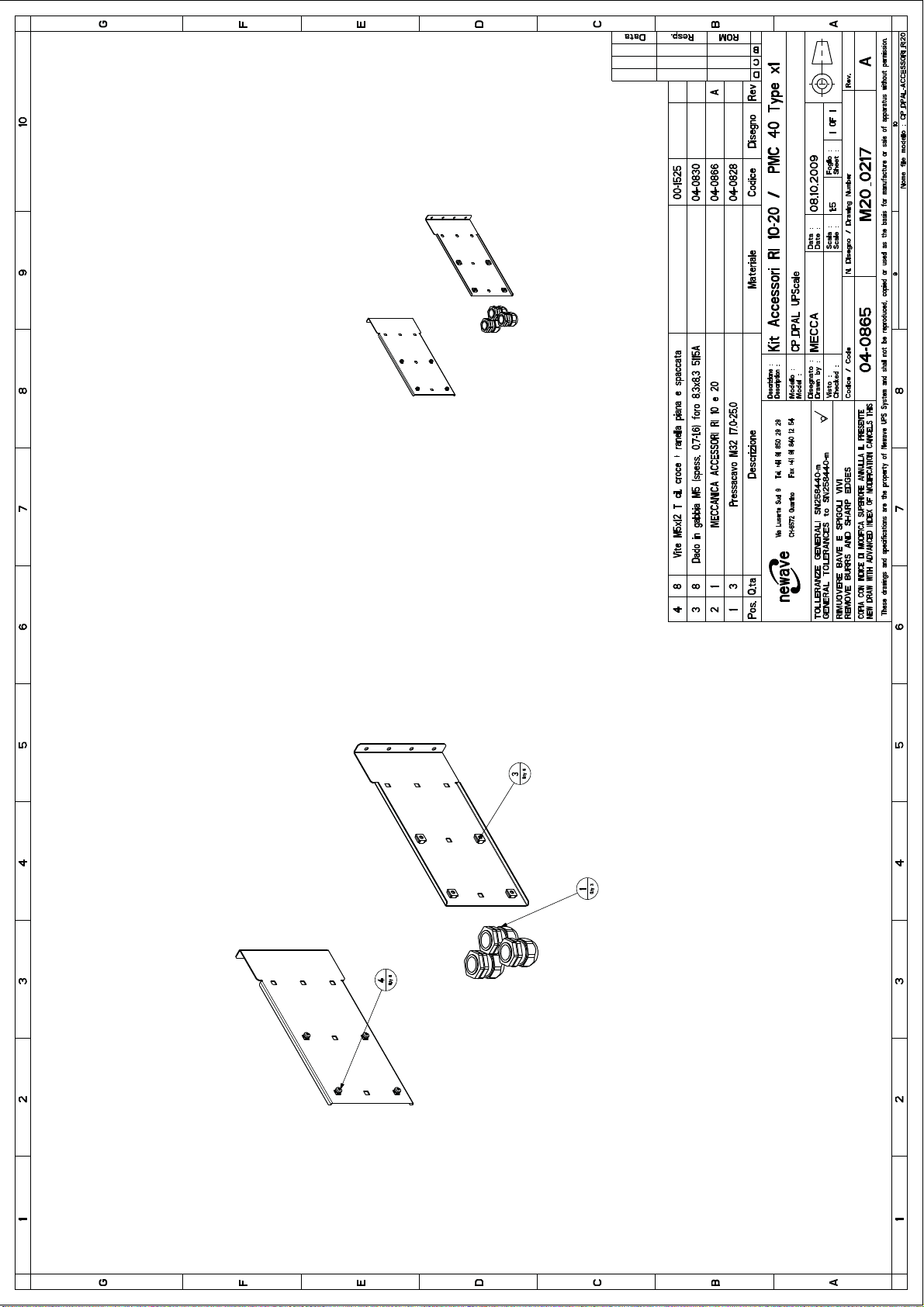
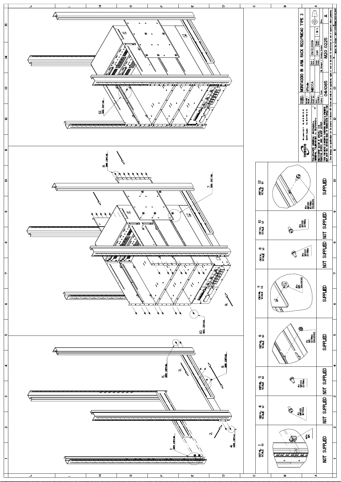
Please follow the instruction drawing on fig. 2.1 – 2.7.
Note: for assembling the sub rack at a 19” rack you have to remove the UPS modules and the battery
shelves, while you need access for screw position (see Detail 12 on figure 2.1 – 2.7)
1.5.3.1 Table of Weight
Section-1
04-3006_S1_OPM_ABB_DPA_UPSCALE_RI_10-80kW_EN_150316.doc Page 17/52 ABB
Modifications reserved
Page 26

1.5.3.2 Mechanical Drawing, Assembling and accessories DPA UPScale RI 10
See drawings on the next pages:
Mechanical: fig.1.1_CP_DPAL-RI10_04-0855_PMC40_TYPE_X1.pdf
Assembling: fig.2.1_CP_DPAL-MONTAGGIO_RI10_PMC40_TYPE_X1
Accessories: fig.3.1_CP_DPAL-ACCESSORI_RI10-20_04-0865_TYPE_x1-x2
Section-1
04-3006_S1_OPM_ABB_DPA_UPSCALE_RI_10-80kW_EN_150316.doc Page 18/52 ABB
Modifications reserved
Page 27
Page 28

Page 29
Page 30

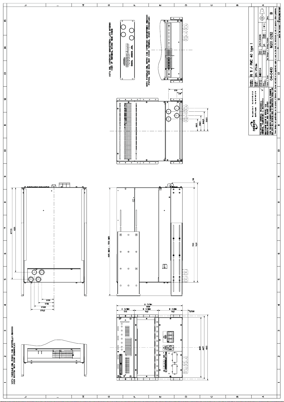
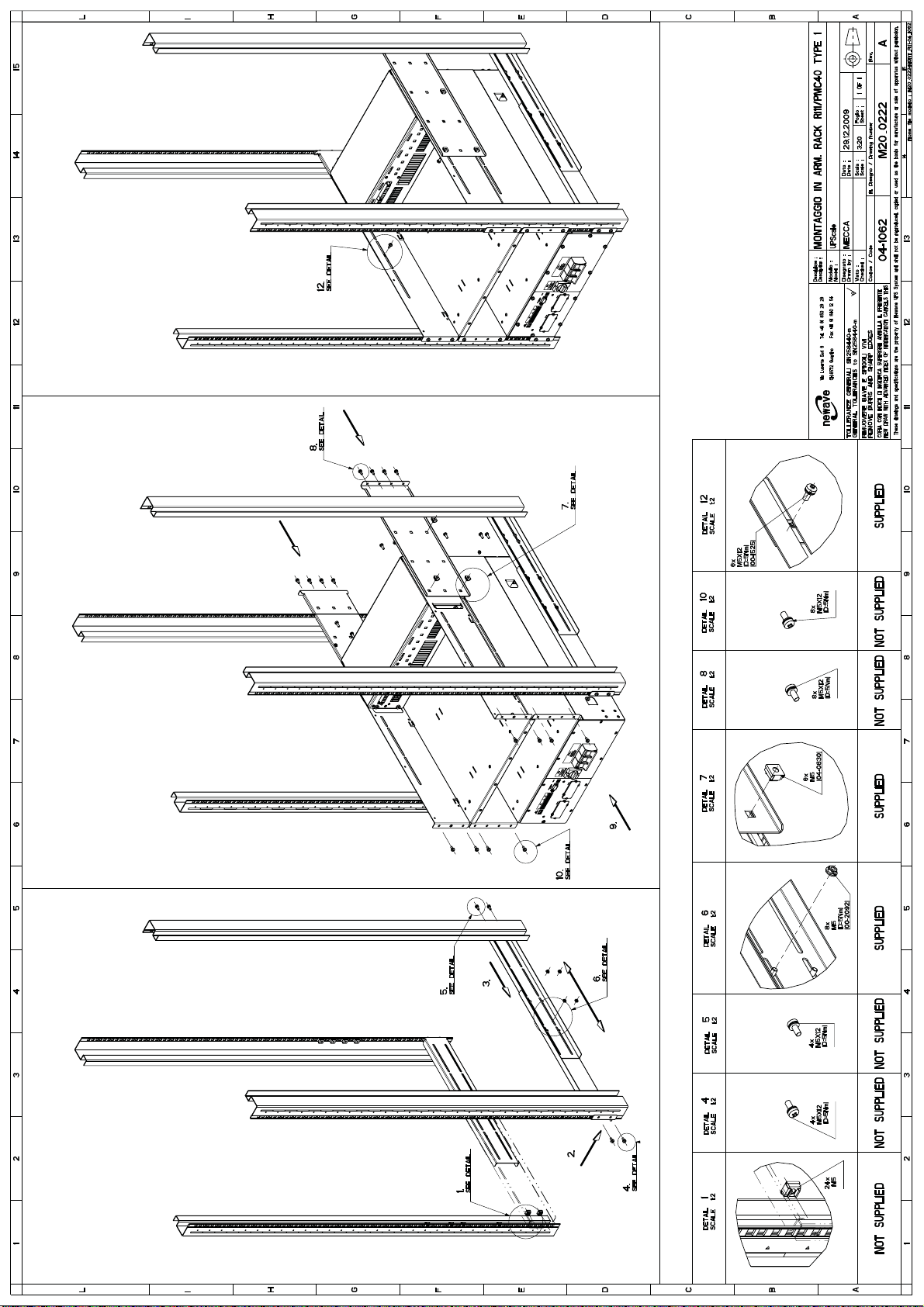
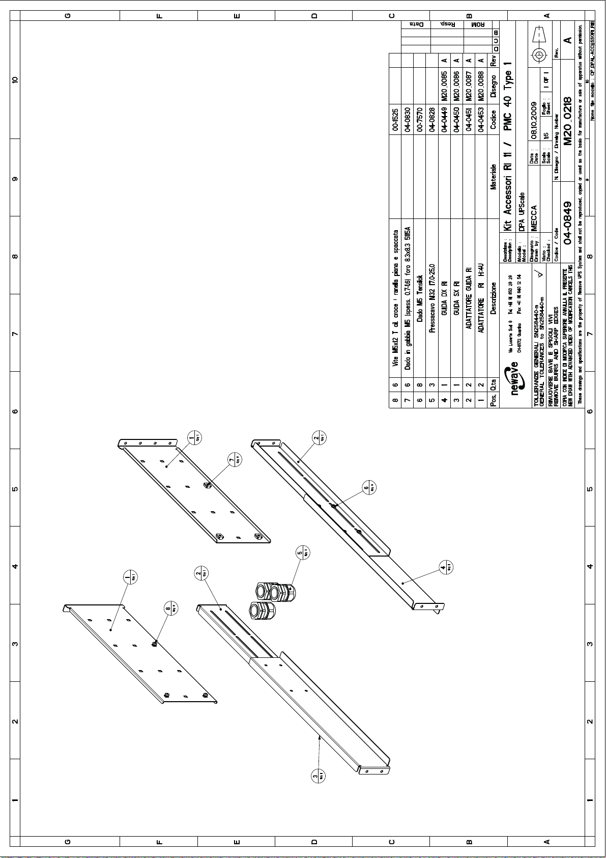
1.5.3.3 Mechanical Drawing, Assembling and accessories DPA UPScale RI 11
See drawings on the next pages:
Mechanical: fig.1.3_CP_DPAL-RI11_04-0410_PMC40_TYPE1
Assembling: fig.2.3_CP_DPAL-MONTAGGIO_RI11_PMC40_TYPE1
Accessories: fig.3.2_CP_DPAL-ACCESSORI_RI11_04-0849_TYPE1
Section-1
04-3006_S1_OPM_ABB_DPA_UPSCALE_RI_10-80kW_EN_150316.doc Page 22/52 ABB
Modifications reserved
Page 31
Page 32
Page 33
Page 34

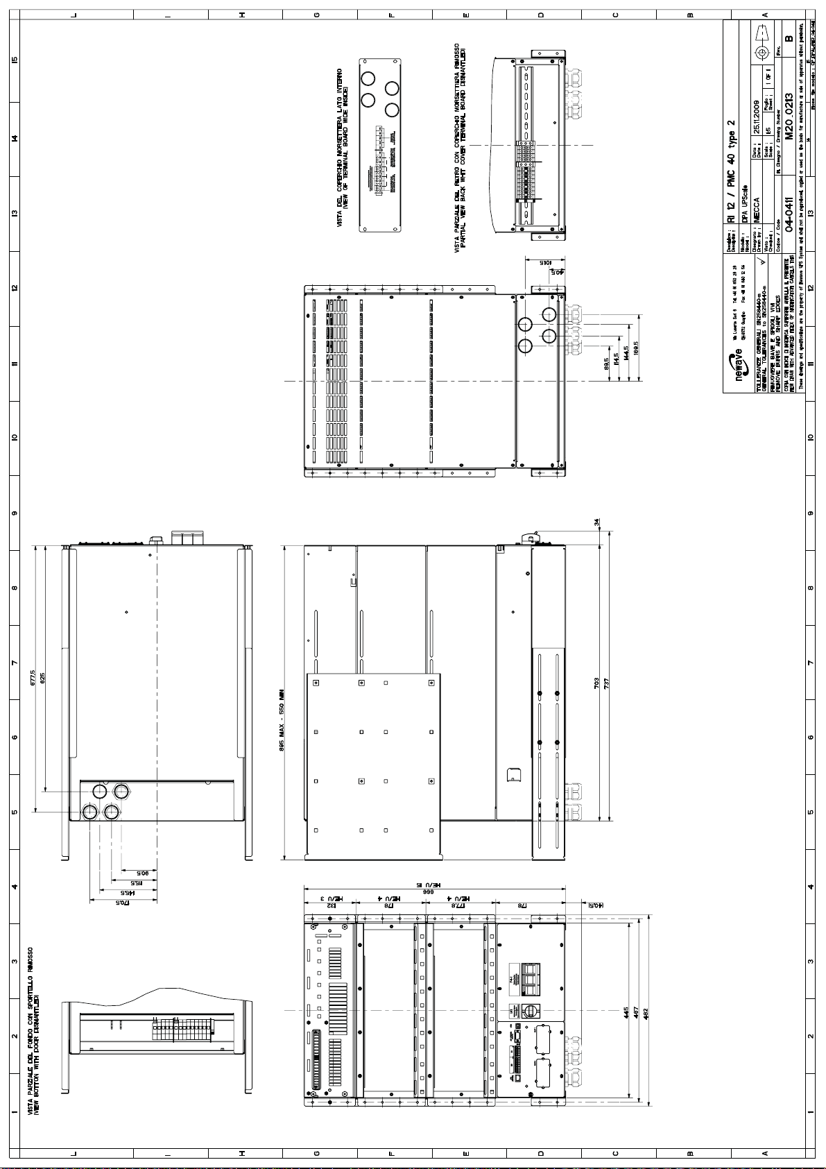
1.5.3.4 Mechanical Drawing, Assembling and accessories DPA UPScale RI 12
See drawings on the next pages:
Mechanical: fig.1.4_CP_DPAL-RI12_04-0411_PMC40_TYPE2
Assembling: fig.2.4_CP_DPAL-MONTAGGIO_RI12_PMC40_TYPE2
Accessories: fig.3.3_CP_DPAL-ACCESSORI_RI12-22_04-0850_TYPE2-3
Section-1
04-3006_S1_OPM_ABB_DPA_UPSCALE_RI_10-80kW_EN_150316.doc Page 26/52 ABB
Modifications reserved
Page 35
Page 36
Page 37
Page 38

1.5.3.5 Mechanical Drawing, Assembling and accessories DPA UPScale RI 20
See drawings on the next pages:
Mechanical: fig.1.2_CP_DPAL-RI20_04-0856_PMC40_TYPE_X2.pdf
Assembling: fig.2.2_CP_DPAL-MONTAGGIO_RI20_PMC40_TYPE_X2
Accessories: fig.3.1_CP_DPAL-ACCESSORI_RI10-20_04-0865_TYPE_x1-x2
Section-1
04-3006_S1_OPM_ABB_DPA_UPSCALE_RI_10-80kW_EN_150316.doc Page 30/52 ABB
Modifications reserved
Page 39
Page 40
Page 41
Page 42

1.5.3.6 Mechanical Drawing, Assembling and accessories DPA UPScale RI 22
See drawings on the next pages:
Mechanical: fig.1.5_CP_DPAL-RI22_04-0412_PMC40_TYPE3
Assembling: fig.2.5_CP_DPAL-MONTAGGIO_RI22_PMC40_TYPE3
Accessories: fig.3.3_CP_DPAL-ACCESSORI_RI12-22_04-0850_TYPE2-3
Section-1
04-3006_S1_OPM_ABB_DPA_UPSCALE_RI_10-80kW_EN_150316.doc Page 34/52 ABB
Modifications reserved
Page 43
Page 44
Page 45
Page 46

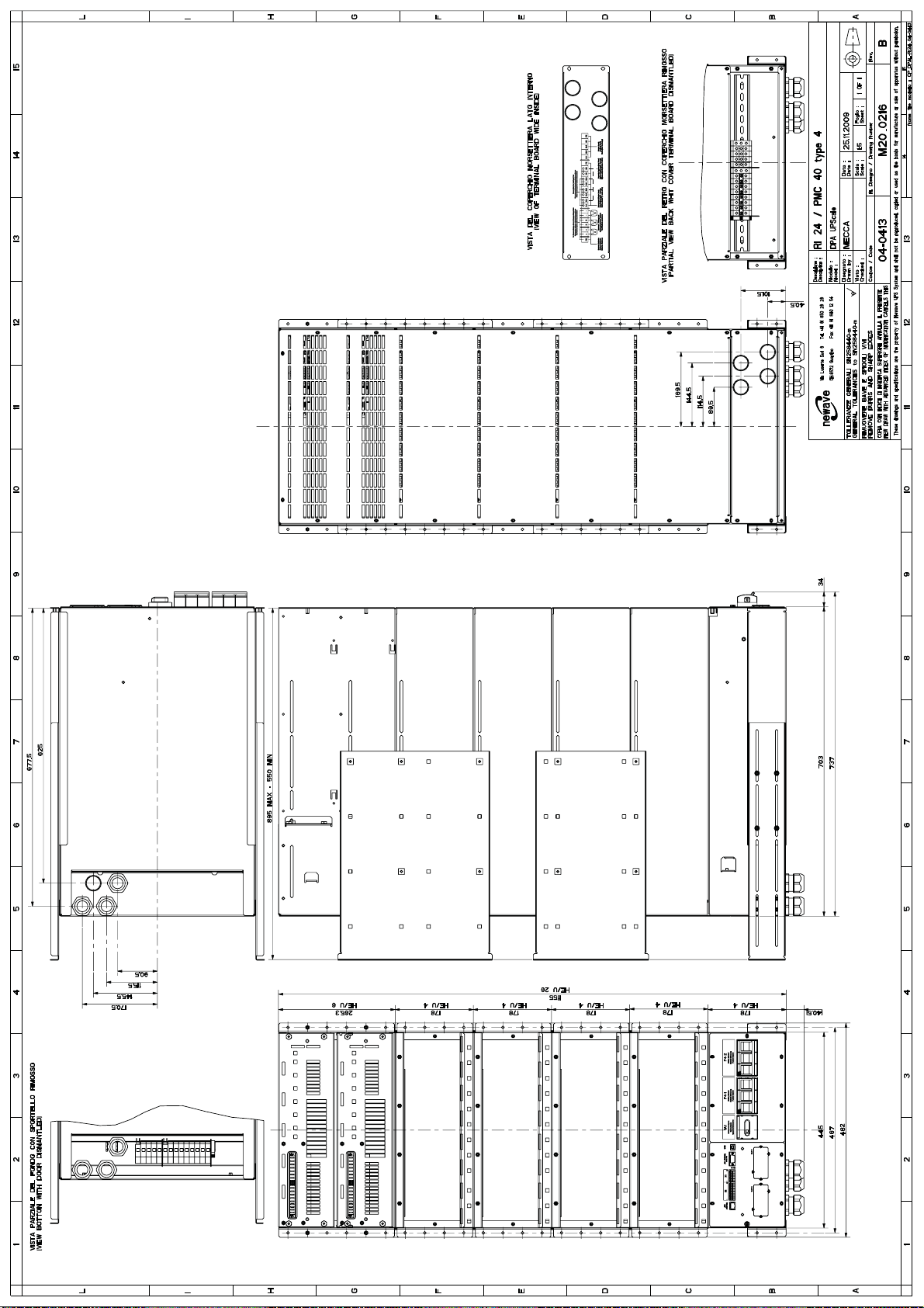
1.5.3.7 Mechanical Drawing, Assembling and accessories DPA UPScale RI 24
See drawings on the next pages:
Mechanical: fig.1.6_CP_DPAL-RI24_04-0413_PMC40_TYPE4
Assembling: fig.2.6_CP_DPAL-MONTAGGIO_RI24_PMC40_TYPE4
Accessories: fig.3.4_CP_DPAL-ACCESSORI_RI24_04-0851_TYPE1
Section-1
04-3006_S1_OPM_ABB_DPA_UPSCALE_RI_10-80kW_EN_150316.doc Page 38/52 ABB
Modifications reserved
Page 47
Page 48
Page 49
Page 50

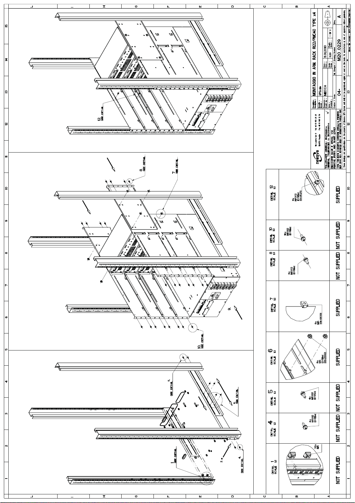
1.5.3.8 Mechanical Drawing, Assembling and accessories DPA UPScale RI 40
See drawings on the next pages:
Mechanical: fig.1.7_CP_DPAL_M20_0227A-RI40-PMC40_TYPE_X4-04_1170.pdf
Assembling: fig.2.7_CP_M20_0229-MONT_RI40-04_a1_2.pdf
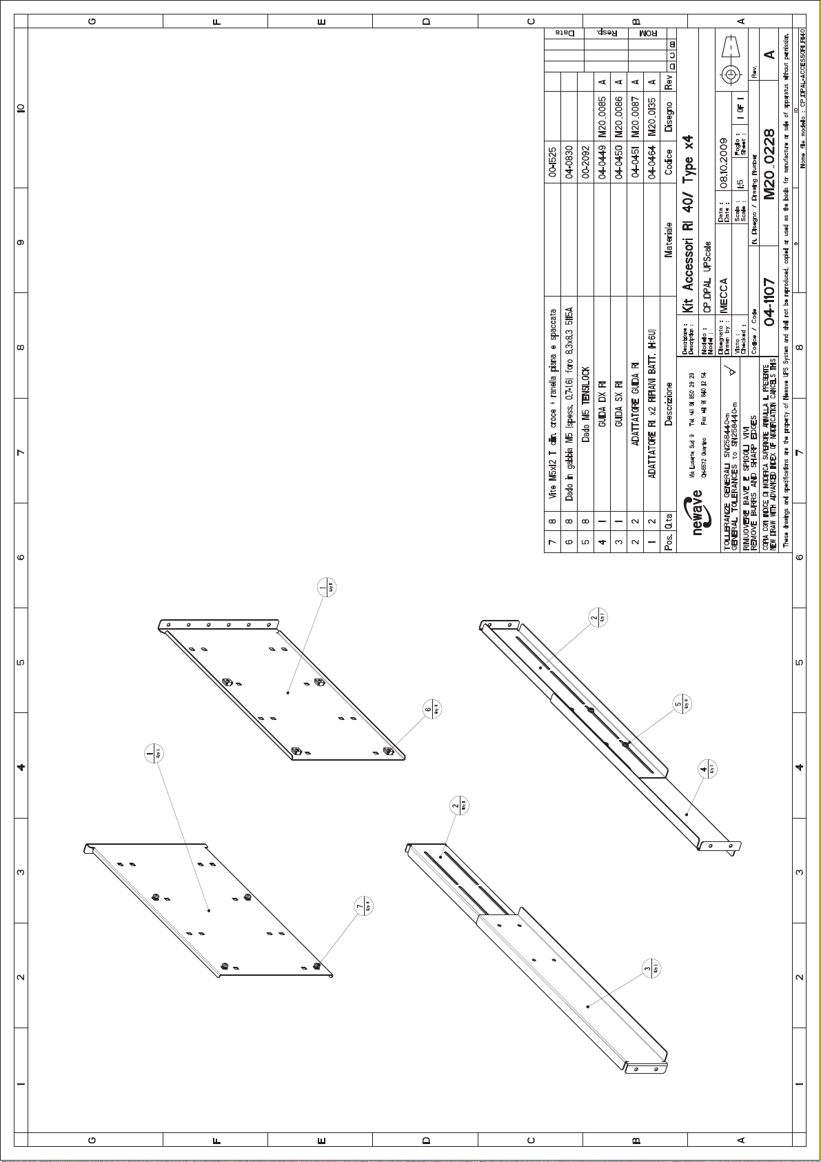
Accessories: fig. 3.5_CP_DPAL-ACESSORI_M20_0228A-ACC_RI40-PMC40_TYPE_X4-04_1107.pdf
Section-1
04-3006_S1_OPM_ABB_DPA_UPSCALE_RI_10-80kW_EN_150316.doc Page 42/52 ABB
Modifications reserved
Page 51

Page 52
Page 53
Page 54
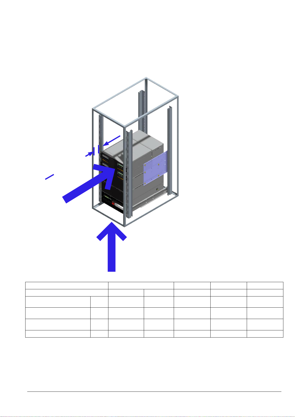
D
o
o
r
w
i
t
h
o
p
e
n
i
n
g
s
m
i
n
.
5
0
m
m
d
i
s
d
a
n
c
e
D
o
o
r
w
i
t
h
o
u
t
o
p
e
n
i
n
g
s
m
i
n
.
1
0
0
m
m
d
i
s
d
a
n
c
e
V
a
n
f
o
r
a
i
r
i
n
l
e
t
F
r
o
n
t
d
o
o
r
w
i
t
h
a
i
r
c
o
o
l
i
n
g
f
l
o
w
Air cooling flow from
double floor
Fig. 4.1 Air cooling flow
Module Range
UPScale M10 or M20
RI10 /10 /12
RI 20/ 22/ 24
RI 40
Module Type
UPScale M10
UPScale M20
1 module min-max
2 modules min-max
4 modules min-max
Heat Dissipation with 100% NNL4)
per Module
W
550
1100
550-1100
1100-2200
2200-4400
Heat Dissipation with 100% NNL4)
Load per Module
BTU/h
1887
3754
1887-3754
3774-7508
7548-15096
Airflow (25° - 30°C) with NNL4)
Load per Module
m
3/h
150
150
150
300
600
Dissipation at no load
W
120
150
120-150
240-300
480-600
1.5.3.9 Air cooling flow DPA UPScale RI
Section-1
4)
NLL means Non-Linear Load according to IEC/EN 62040-3.
04-3006_S1_OPM_ABB_DPA_UPSCALE_RI_10-80kW_EN_150316.doc Page 46/52 ABB
Modifications reserved
Page 55
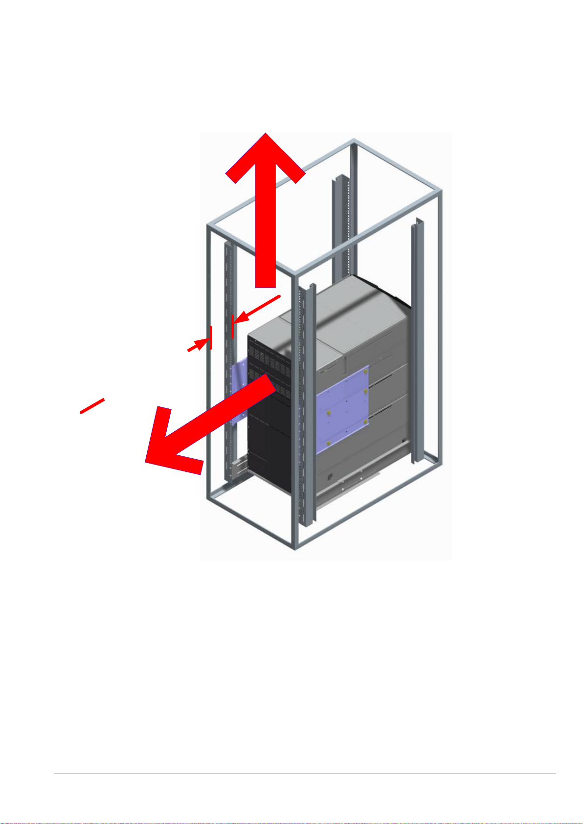
Air cooling flow outlet
Air cooling flow with roof outlet
Door with openings
min
.
50
mm disdance
Door without openings
min
.
200
mm disdance
Fig. 4.2 Air cooling flow
Section-1
04-3006_S1_OPM_ABB_DPA_UPSCALE_RI_10-80kW_EN_150316.doc Page 47/52 ABB
Modifications reserved
Page 56
WARNING!
THE INSTRUCTION IN THIS USER MANUAL HAVE ALWAYS TO BE FOLLOWED
IN ORDER TO AVOID INJURIES FROM ELECTRICAL IMPACTS.
WARNING!
ALL THE OPERATIONS IN THIS MANUAL MUST BE PERFORMED BY
CERTIFIED ELECTRICIANS OR BY QUALIFIED INTERNAL PERSONNEL.
DO NOT OPERATE IN CASE OF PRESENCE OF WATER OR MOISTURE.
BY OPENING OR REMOVING THE UPS-COVERS YOU RUN RISK OF
EXPOSURE TO DANGEROUS VOLTAGES
PHYSICAL INJURY OR DEATH MAY FOLLOW, OR DAMAGE MAY OCCUR TO
THE UPS, OR THE LOAD EQUIPMENT IF THESE INSTRUCTIONS ARE
IGNORED.
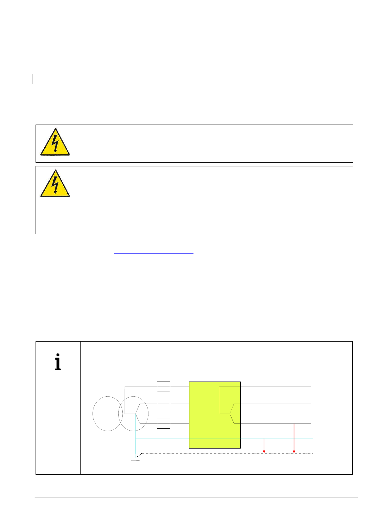
IMPORTANT
NOTES
INPUT NEUTRAL IS REQUIRED TO OPERATE THE RECTIFIER.
In TN-S Systems, no 4-pole input switches or circuit breakers should be used. If you have to
use for other reason a 4-pole switch, you have to be aware that, when open, the system - UPS
and all downstream equipment - are floating against the PE.
0V
230V
UPS
Section-1
1.6 ELECTRICAL INSTALLATION
The customer has to supply the wiring to connect the UPS to the local power source see Section 2, chapter 2.1.
The electrical installation procedure is described in the following text. The installation inspection and initial start up
of the UPS and extra battery cabinet must be carried out by a qualified service personnel such as a licensed
service engineer from the manufacturer or from an agent certified by the manufacturer.
To ensure correct operation of the UPS and its ancillary equipment it is necessary to provide the mains cables with
appropriate fuse protection.
See Section 2, chapter 2.1.2
The UPS unit has the following power connections:
Rectifier (In): Three-phase (1L1, 1L2, 1L3), Neutral (1N) and protective earth (PE)
connection for the rectifier input
Bypass (In): Three-phase (2L1, 2L2, 2L3), Neutral (2N)
connection for the bypass if used as Dual Feed input
Load (Out): Three-phase (3L1, 3L2, 3L3), Neutral (3N) and protective earth (PE)
connection for the load output
External Battery: Plus (+), Common (N), Minus (-) and protective earth (PE)
connection for the external batteries
04-3006_S1_OPM_ABB_DPA_UPSCALE_RI_10-80kW_EN_150316.doc Page 48/52 ABB
Modifications reserved
Page 57
NOTE!
Before proceeding read the chapter ELECTRICAL INSTALLATION
(SECTION 1) and insure before starting connecting the cable to the UPS
that:
NOTE!
INPUT NEUTRAL IS REQUIRED TO OPERATE THE RECTIFIER.
1.6.1 PREPARATION FOR THE INPUT CABLING
Mains voltage (INPUT VOLTS) and frequency (FREQUENCY) correspond to the values indicated on
the Nameplate of the UPS.
Earth connection is performed in accordance with the prescribed IEC Standards or with local
regulations;
UPS is connected to the mains through a Low Voltage (LV)-Distribution Board with a separate mains
line (protected with a circuit breaker or fuse) for the UPS.
Section-1
Provide input fuses and cables according to
See Section 2, chapter 2.1.2 or in accordance with the prescribed IEC
Standards or with the local regulations.
The input of the UPS must be fitted with circuit breakers or other kind of protection. The circuit breakers will be
connected between the mains supply and the UPS and will provide additional protection to the UPS in the event of
overloads and short circuits.
1.6.1.1 Mains supply and Earth connection
To ensure protection of personnel during the installation of UPS make sure that the connections are performed
under the following conditions:
No mains voltage is present
All Loads are shut down and disconnected
UPS is shut down and voltage-free
UPS-Module is fitted in its correct position
Maintenance Bypass IA1 is open and in position OFF;
Remove Terminal cover of the UPS on the rear site
1. Connect first the Earthing wire coming from the Low Voltage-Distribution Board to the terminal "PE".
2. Connect the input power cable coming from the Low Voltage-Distribution Board to the terminals of the
UPS showed in
See Section 2, chapter 2.1.2
3. Keep the phase rotation in clock-wise sense.
Under the connection terminal of the UPS there is a cable-fixing rail to ensure that the cables have been fastened
properly.
NOTE: The UPS is provided with facilities for both single feed (one common input cable for rectifier
and bypass) and dual feed (separate input cable for rectifier and bypass).
04-3006_S1_OPM_ABB_DPA_UPSCALE_RI_10-80kW_EN_150316.doc Page 49/52 ABB
Modifications reserved
Page 58
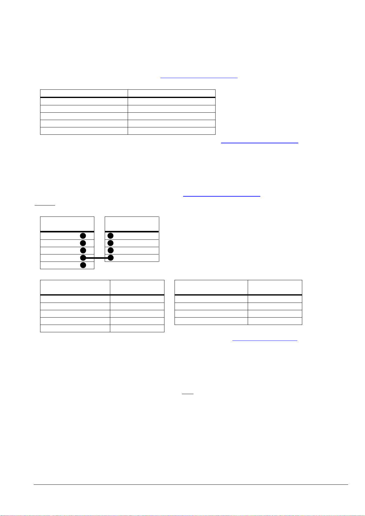
MAINS INPUT CABLE
UPS TERMINAL
Phase L1
1L1
Phase L2
1L2
Phase L3
1L3
NEUTRAL
1N
EARTH
PE
UPS TERMINAL
Rectifier
UPS TERMINAL
Bypass
1L1
2L1
1L2
2L2
1L3
2L3
1N
2N
PE
MAINS INPUT CABLE
UPS TERMINAL
Rectifier
BYPASS INPUT CABLE
UPS TERMINAL
Bypass
Phase L1
1L1 Phase L1
2L1
Phase L2
1L2 Phase L2
2L2
Phase L3
1L3 Phase L3
2L3
NEUTRAL
1N NEUTRAL
2N
EARTH
PE
1.6.1.2 Single Input Feed
Section-1
To achieve correct Input Cabling see Drawing
See Section 2, chapter 2.1.2
For single input feed connect the mains input cable to UPS Terminal Block according to the following table:
For minimum recommended Input Cable Sections and Fuse Ratings See Section 2, chapter 2.1.2
Under the connection terminal of the UPS there is a cable-fixing rail to ensure that the cables have been fastened
properly.
1.6.1.3 Dual Input Feed
To achieve correct input cabling see Terminal Block in
See Section 2, chapter 2.1.2
NOTE: The UPS is supplied (as standard version) with facilities for a single cable feed (for rectifier and bypass).
If dual feed is required unscrew the terminal bridges between (L1,L2,L3, only)
For dual input feed connect the mains input cables to UPS Terminal according to following tables:
For minimum recommended Input Cable Sections and Fuse Ratings see Section 2, chapter 2.1.2
Under the connection terminal of the UPS there is a cable-fixing rail to ensure that the cables have been fastened
properly.
1.6.1.4 Preparation for the Output Cabling
Before you start connecting the loads, ensure that the sum of the indicated UPS-module rated powers (OUTPUT
POWER) on the nameplates (on the front side of the UPS-modules) is equal to or larger than the total load
requirements.
The output of the UPS must be fitted with circuit breakers or other kind of protection. These circuit breakers will be
connected between the loads and the UPS and will provide additional protection to the UPS in the event of
overloads and short circuits.
These circuit breakers will enable the protection of each load separately.
The size of the circuit breakers depends on the load rating of the load sockets.
The circuit breakers must comply with the prescribed IEC Standards. It is recommended to provide a separate
output distribution board for the load.
04-3006_S1_OPM_ABB_DPA_UPSCALE_RI_10-80kW_EN_150316.doc Page 50/52 ABB
Modifications reserved
Page 59

Section-1
The following values should be indicated on the output distribution board:
Maximum total load rating;
Maximum load rating of the load sockets.
If a common distribution board is used (sockets for Mains and UPS voltage), ensure that on each socket there is an
indication of the applied voltage (“Mains” or “UPS”).
Output power cable ratings should be in accordance with the recommended cable sections and fuses ratings or in
accordance with the prescribed IEC Standards or with the local regulations.
Under the connection terminal of the UPS there is a cable-fixing rail to ensure that the cables have been fastened
properly.
Ensure that the earthing is performed in accordance with the prescribed IEC Standards or with the local regulations.
1.6.1.5 Connection of the Load
To ensure protection of the personnel during the installation of the UPS make sure that the connections are
performed under the following conditions:
No mains voltage is present;
All loads are shut down and disconnected;
PMC is shut down and voltage-free.
Before connecting the output power cables make sure that:
UPS-Module is fitted in its correct position;
Maintenance bypass is in position OFF;
Remove the terminal cover of the UPS.
Connect the output power cable coming from the LV-Distribution Board to the terminals of the UPS as shown in
drawing in
Section 2, chapter 2 (Front view of the DPA UPScale TM )
04-3006_S1_OPM_ABB_DPA_UPSCALE_RI_10-80kW_EN_150316.doc Page 51/52 ABB
Modifications reserved
Page 60

1.6.2 INSTALLATION CHECKLIST
All packing materials and restraints have been removed from each cabinet.
Each RI-Enclosure of the UPS system is placed in the installed location.
All conduits and cables are properly routed to the UPS and auxiliary cabinets.
All power cables are properly sized and terminated.
A ground conductor is properly installed.
If the RI-Enclosure does not use all module mounting locations, the provided protective
covers are installed on the front and back of the enclosure.
Battery cabinet installation instructions have been completed.
Section-1
Air conditioning equipment is installed and operating properly.
The area around the installed UPS system is clean and dust-free. (It is recommended that
the UPS be installed on a level floor suitable for computer or electronic equipment.
Adequate workspace exists around the UPS and other cabinets.
Adequate lighting is provided around all UPS equipment.
Any optional accessories are mounted in their installed location and properly wired.
Summary alarms and/or building alarms are wired appropriately. (OPTIONAL)
Startup and operational checks performed by certified service personnel.
All network connections are completed.
04-3006_S1_OPM_ABB_DPA_UPSCALE_RI_10-80kW_EN_150316.doc Page 52/52 ABB
Modifications reserved
Page 61

Section-2
CONTENTS SECTION-2
2.1 BLOCK DIAGRAM .................................................................................................................... 2
2.1.1 WIRING AND BLOCK DIAGRAMS FOR ALL FRAMES AND MODULES .......................... 2
2.1.2 RECOMMENDED CABLE SECTIONS & FUSE RATINGS ................................................. 2
2.1.2.1 Terminal connections overview .................................................................................... 2
2.1.3 BLOCK DIAGRAM DPA UPSCALE™ ................................................................................. 3
2.1.3.1 Single Feed input (Standard Version) .......................................................................... 3
2.1.3.2 SINGLE FEED INPUT / Cable Sections ....................................................................... 3
2.1.3.3 Dual feed input (Optional Version) ............................................................................... 4
2.1.3.4 Dual FEED INPUT / Cable Sections ............................................................................ 4
2.2 FRONT VIEW ............................................................................................................................ 5
2.2.1 FRONT VIEW OF DPA UPScale RI 10 AND CONNECTION TERMINALS ......................... 5
2.2.2 FRONT VIEW OF DPA UPScale RI 11 AND CONNECTION TERMINALS ......................... 6
2.2.3 FRONT VIEW OF DPA UPScale RI 12 AND CONNECTION TERMINALS ......................... 7
2.2.4 FRONT VIEW OF DPA UPScale RI 20 AND CONNECTION TERMINALS ......................... 8
2.2.5 FRONT VIEW OF DPA UPScale RI 22 AND CONNECTION TERMINALS ......................... 9
2.2.6 FRONT VIEW OF DPA UPScale RI 24 AND CONNECTION TERMINALS ....................... 10
2.2.7 FRONT VIEW OF DPA UPScale RI 40 AND CONNECTION TERMINALS ....................... 11
2.3 BATTERY CONNECTIONS ..................................................................................................... 12
2.3.1 INTERNAL BATTERY MODULES .................................................................................... 12
2.3.2 EXTERNAL BATTERY CABINET AND BATTERY (NOT FORSEEN) ............................... 14
04-3006_S2_OPM_ABB_DPA_UPSCALE_RI_10-80kW_EN_150316.doc Page 1/14 ABB
Modifications reserved
Page 62
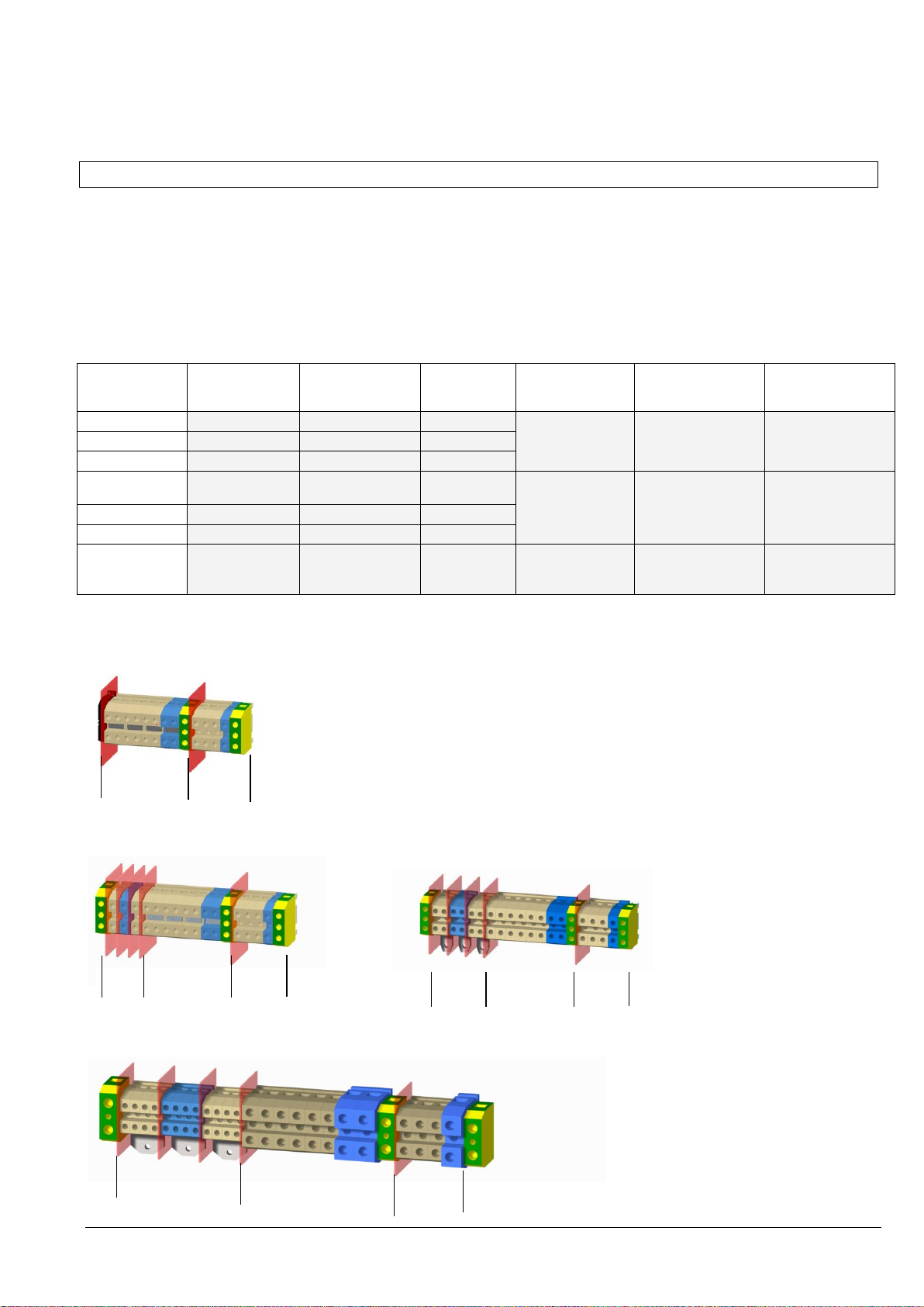
FRAME TYPE
Terminals (T)
Connection Bar (B)
Battery Earth
PE
Separate. Battery
(+ / N / - )
Common
Battery
(+ / N / - )
Input Bypass
3+N
Input Rectifier
3+N+PE
Output load
3+N+PE
UPScale RI 10
16/25mm2 (T)
3 x 10/16mm2 (T)
n.a
4 x 10/16 mm2 (T)
5 x 10/16 mm2 (T)
5 x 10/16 mm2 (T)
UPScale RI 11
n.a.
n.a.
n.a.
UPScale RI 12
n.a.
n.a.
n.a.
UPScale RI20
16/25mm2 (T)
2x
(3 x 10/16mm2) (T)
3 x M5 (B)
4 x 16/25 mm2 (T)
5 x 16/25 mm2 (T)
5 x 16/25 mm2 (T)
UPScale RI 22
n.a.
n.a.
n.a.
UPScale RI 24
n.a.
n.a.
n.a.
UPScale RI40
50 mm2 (T)
4x
(3 x 10/16mm2) (T)
3 x M6 (B)
3 x 50 mm2 (T)
+ N 70/95 mm2
(T)
3 x 50 mm2 (T)
+ N 70/95 mm2 (T)
+PE 50 mm2 (T)
3 x 50 mm2 (T)
+ N 70/95 mm2 (T)
+PE 50 mm2 (T)
Batt. Input Output
Batt. Input Output
Batt. Input Output
Input Output
2.1 BLOCK DIAGRAM
2.1.1 WIRING AND BLOCK DIAGRAMS FOR ALL FRAMES AND MODULES
The customer has to supply the wiring to connect the UPS to the local power source. The installation inspection
and initial start up of the UPS and extra battery cabinet must be carried out by a qualified service personnel
such as a licensed service engineer from the manufacturer or from an agent certified by the manufacturer.
2.1.2 RECOMMENDED CABLE SECTIONS & FUSE RATINGS
2.1.2.1 Terminal connections overview
Section-2
n.a. = not allowed
UPScale RI 11, RI 12, RI 22, RI 24
(on rear site)
UPScale RI 10 UPScale RI 20
(on rear site) (on rear site)
UPScale RI 40
(on rear site)
04-3006_S2_OPM_ABB_DPA_UPSCALE_RI_10-80kW_EN_150316.doc Page 2/14 ABB
Modifications reserved
Page 63
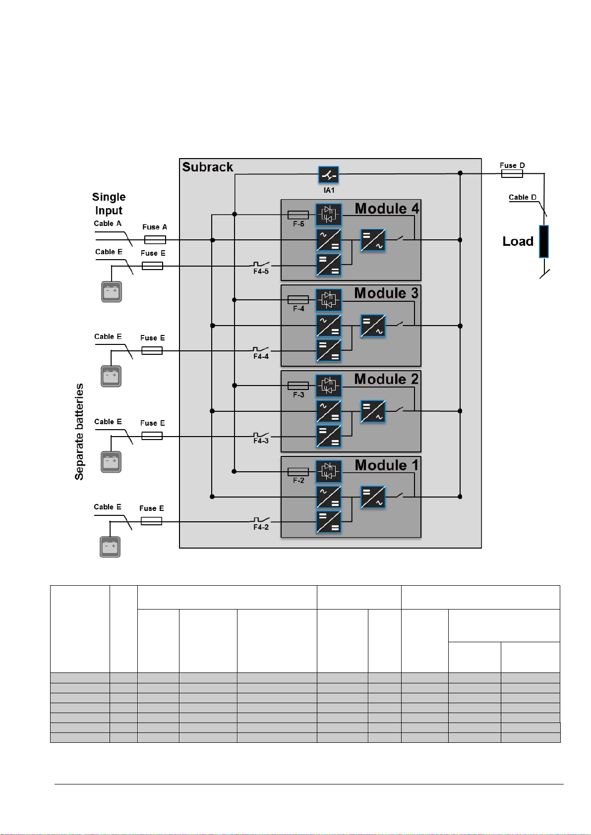
Enclosure
type
Load
in KW
Input 3x400V/230V
Output 3x400V/230V
@ cosphi 1.0
Battery
Fuse A
(Agl/CB)
Cable A
(mm2)
(IEC 60950-1)
Max. Input Current
with battery
charging (A)
Cable D
(mm2)
(IEC 60950-1)
I nom
(A)
Fuse E
+ / N / -
(Agl/CB)
Cable E (mm2)
Only for external Batteries
+ / N / -
Com.
Battery
Sep. Battery
Upscale RI 10
20
3x40A
5x6
34
5x6
29 A
3x63A
n.a.
3x10
Upscale RI 11
20
3x40A
5x6
34
5x6
29 A
3x63A
n.a.
n.a.
Upscale RI 12
20
3x40A
5x6
34
5x6
29 A
3x63A
n.a.
n.a.
Upscale RI 20
40
3x80A
5x16
68
5x16
58 A
3x100A *1
3x25 *1
2x(3x10)
Upscale RI 22
40
3x80A
5x16
68
5x16
58 A
3x100A *1
n.a.
n.a.
Upscale RI 24
40
3x80A
5x16
68
5x16
58 A
3x100A *1
n.a.
n.a.
Upscale RI 40
80
3x160A
5x50
136 A
5x50
116 A
3x224A*1
3x95 *1
4x(3x10)
2.1.3 BLOCK DIAGRAM DPA UPSCALE™
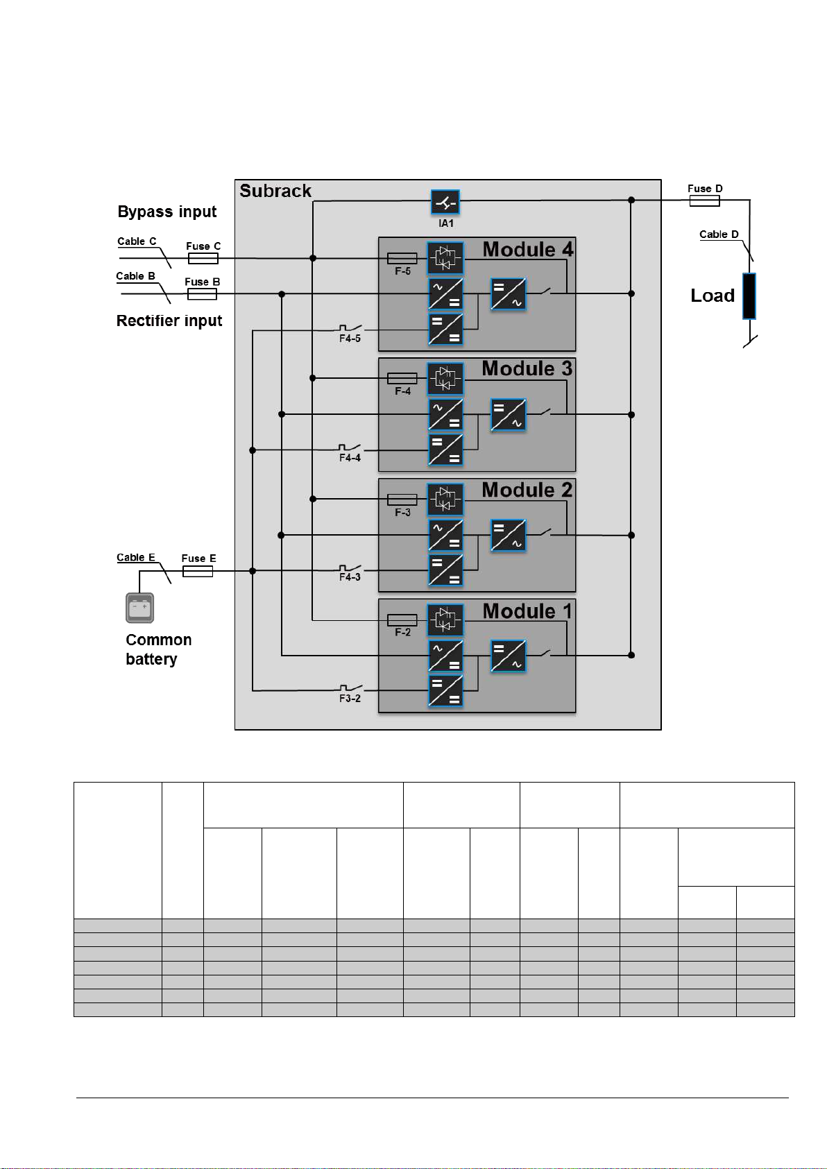
2.1.3.1 Single Feed input (Standard Version)
Cable Sections and Fuse Ratings recommended. Alternatively, local standards to be respected
Section-2
2.1.3.2 SINGLE FEED INPUT / Cable Sections
*1 only valid for common battery use
n.a. = not allowed
04-3006_S2_OPM_ABB_DPA_UPSCALE_RI_10-80kW_EN_150316.doc Page 3/14 ABB
Modifications reserved
Page 64
Enclosure
type
Load
in KW
Input 3x400V/230V
Bypass
3x400V/230V
Output
3x400V/230V
@ cosphi 1.0
Battery
Fuse B
(Agl/CB)
Cable B
(mm2)
(IEC 60950-1)
Max. Input
Current
with battery
charging
(A)
Fuse C
(Agl/CB)
Cable C
(mm2)
(IEC
60950-1)
Cable D
(mm2)
(IEC
60950-1)
I nom
Fuse E
+/N/-
(Agl/CB)
Cable E (mm2)
Only for external
Batteries
+ / N / -
Com.
Battery
Sep.
Battery
Upscale RI 10
20
3x40A
5x6
34
3x40A
4x6
5x6
29 A
3x63A
n.a.
3x10
Upscale RI 11
20
3x40A
5x6
34
3x40A
4x6
5x6
29 A
3x63A
n.a.
n.a.
Upscale RI 12
20
3x40A
5x6
34
3x40A
4x6
5x6
29 A
3x63A
n.a.
n.a.
Upscale RI 20
40
3x80A
5x16
68
3x80A
4x16
5x16
58 A
3x100A *1
3x25 *1
2x(3x10)
Upscale RI 22
40
3x80A
5x16
68
3x80A
4x16
5x16
58 A
3x100A *1
n.a.
n.a.
Upscale RI 24
40
3x80A
5x16
68
3x80A
4x16
5x16
58 A
3x100A *1
n.a.
n.a.
Upscale RI 40
80
3x160A
5x50
136 A
3x160A
4x50
5x50
116 A
3x224A*1
3x95 *1
4x(3x10)
2.1.3.3 Dual feed input (Optional Version)
Cable Sections and Fuse Ratings recommended. Alternatively, local standards to be respected
Section-2
*1 only valid for common battery use
n.a. = not allowed
04-3006_S2_OPM_ABB_DPA_UPSCALE_RI_10-80kW_EN_150316.doc Page 4/14 ABB
Modifications reserved
2.1.3.4 Dual FEED INPUT / Cable Sections
Page 65
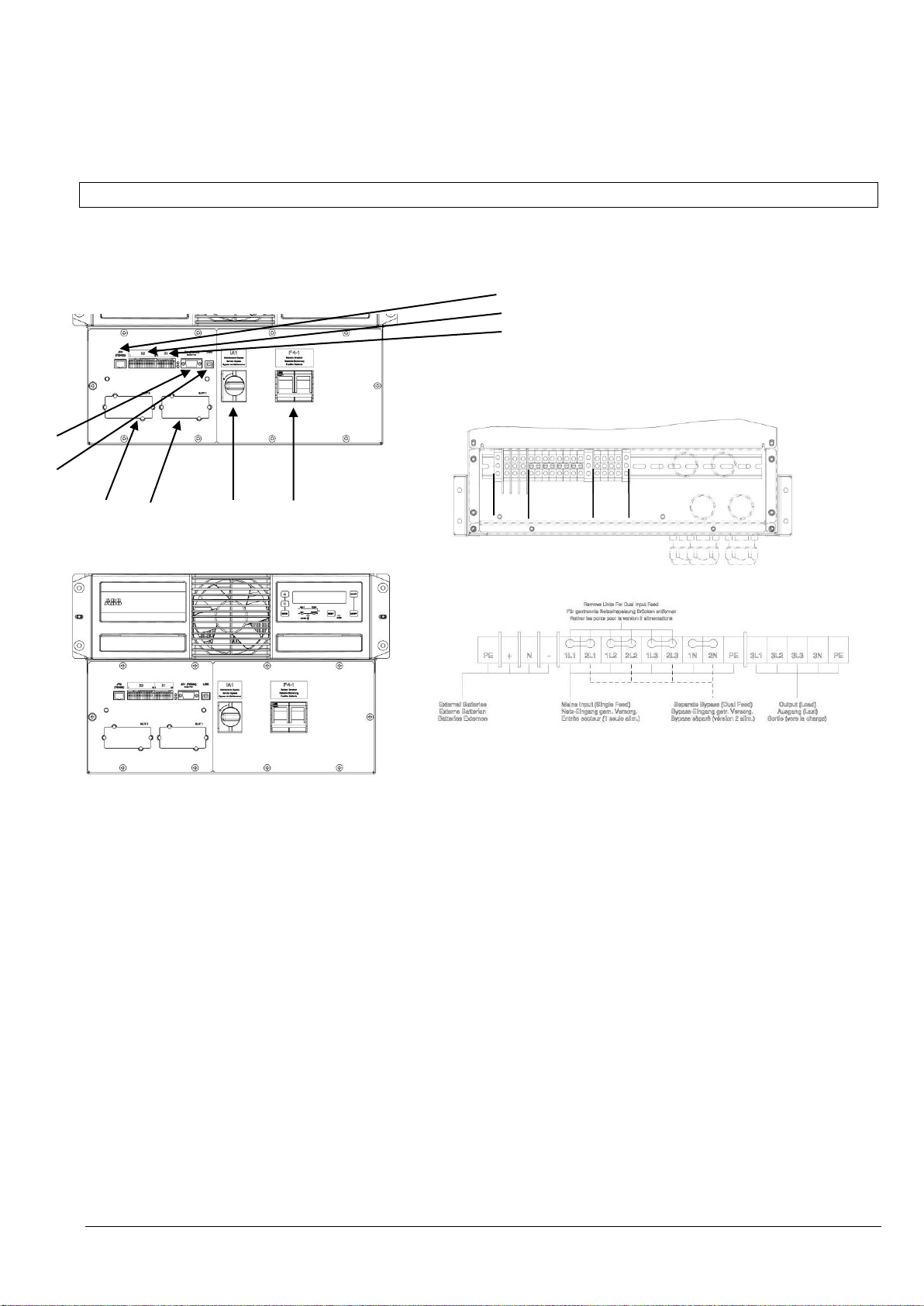
Front side
Rear Side Terminal blocks
Terminal covers and indications
1 Not used JR2 forseen for RJ45 Plug
2 X2 Customer interface on Phoenix Terminals = Potential free contacts
X1 Customer Inputs (detail see Section 3 / 3.1.2 )
3 LED red /green
4 JD1 RS232 / Sub D9/ female, PC interface
5 USB PC Interface
6 SNMP Slot for optional SNMP card ONLY
7 Modem Slot for optional Modem/Ethernet card ONLY
8 Battery terminal + / N / - for Single battery 10/16 mm2
9 Input Bypass terminal for Dual Input feed 10/16 mm2
10 Input Rectifier terminal for Single feed 10/16 mm2
11 Output Load terminal 10/16 mm2
12 F 4-1 Battery Circuit Breaker 2x63 A / 800 VDC
13 IA1 Maintenance Bypass
Wiring see page 2 section 2.1
4
5
6 7 13 12
1
2
3
8 9+10 11
2.2 FRONT VIEW
2.2.1 FRONT VIEW OF DPA UPScale RI 10 AND CONNECTION TERMINALS
Section-2
04-3006_S2_OPM_ABB_DPA_UPSCALE_RI_10-80kW_EN_150316.doc Page 5/14 ABB
Modifications reserved
Page 66
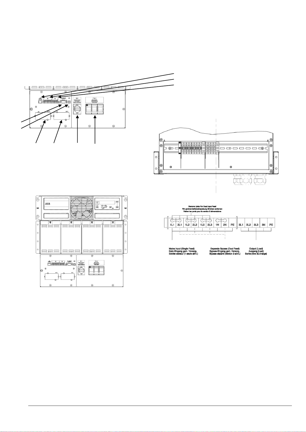
Front side
Rear Side Terminal blocks
Terminal covers and indications
1 Not used JR2 forseen for RJ45 Plug
2 X2 Customer interface on Phoenix Terminals = Potential free contacts
X1 Customer Inputs (detail see Section 3 / 3.1.2 )
3 LED red /green
4 JD1 RS232 / Sub D9/ female, PC interface
5 USB PC Interface
6 SNMP Slot for optional SNMP card ONLY
7 Modem Slot for optional Modem/Ethernet card ONLY
8 Input Bypass terminal for Dual Input feed 10/16 mm2
9 Input Rectifier terminal for Single feed 10/16 mm2
10 Output Load terminal 10/16 mm2
11 F4-1 Battery Circuit Breaker 3x63 A / 800 VDC
12 IA1 Maintenance Bypass
Wiring see page 2 section 2.1
6 7 12 11
1
2
3
8+9 10
4
5
2.2.2 FRONT VIEW OF DPA UPScale RI 11 AND CONNECTION TERMINALS
Section-2
04-3006_S2_OPM_ABB_DPA_UPSCALE_RI_10-80kW_EN_150316.doc Page 6/14 ABB
Modifications reserved
Page 67
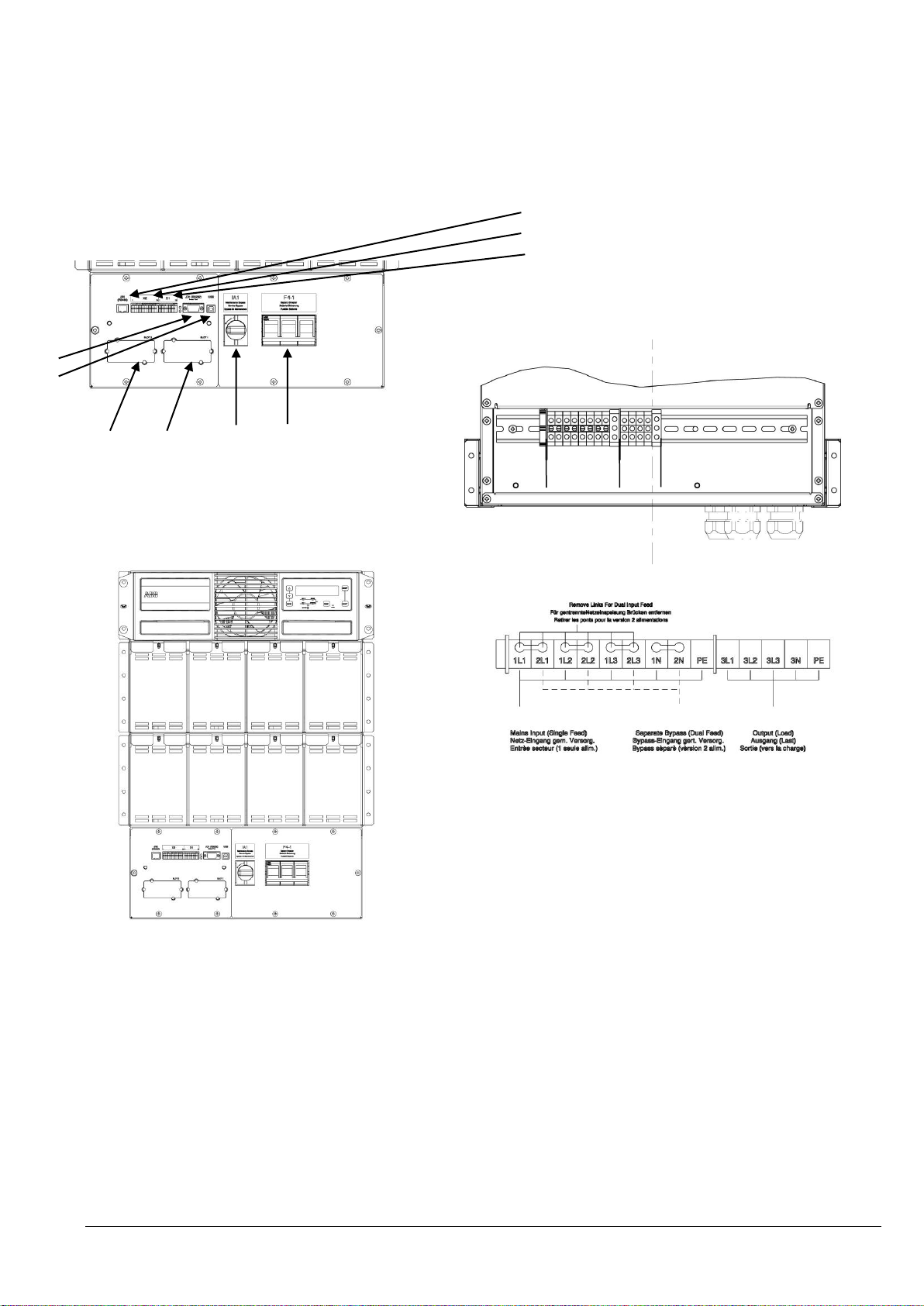
Front side
Rear Side Terminal blocks
Terminal covers and indications
1 Not used JR2 forseen for RJ45 Plug
2 X2 Customer interface on Phoenix Terminals = Potential free contacts
X1 Customer Inputs (detail see Section 3 / 3.1.2 )
3 LED red /green
4 JD1 RS232 / Sub D9/ female, PC interface
5 USB PC Interface
6 SNMP Slot for optional SNMP card ONLY
7 Modem Slot for optional Modem/Ethernet card ONLY
8 Input Bypass terminal for Dual Input feed 10/16 mm2
9 Input Rectifier terminal for Single feed 10/16 mm2
10 Output Load terminal 10/16 mm2
11 F4-1 Battery Circuit Breaker 3x63 A / 800 VDC
12 IA1 Maintenance Bypass
Wiring see page 2 section 2.1
6 7 12 11
4
5
8+9 10
1
2
3
2.2.3 FRONT VIEW OF DPA UPScale RI 12 AND CONNECTION TERMINALS
Section-2
04-3006_S2_OPM_ABB_DPA_UPSCALE_RI_10-80kW_EN_150316.doc Page 7/14 ABB
Modifications reserved
Page 68
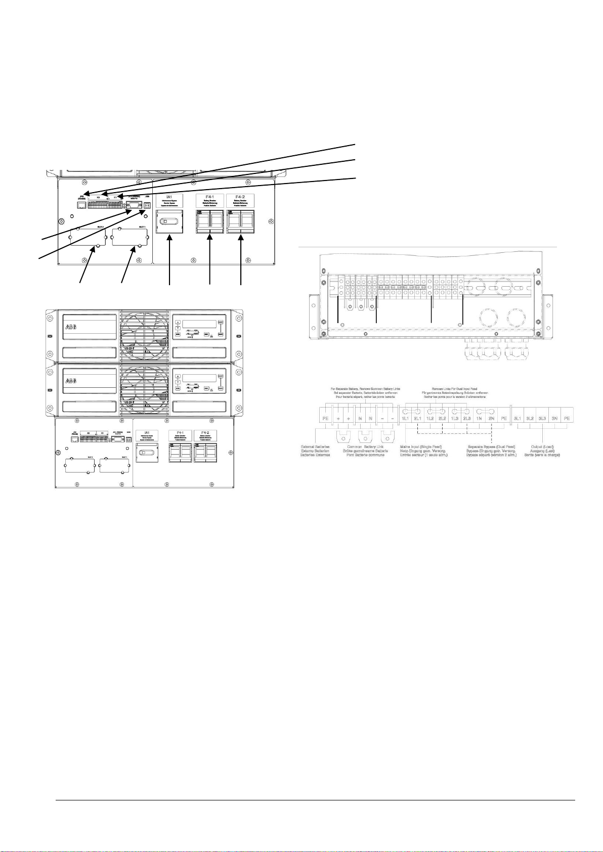
Front side
Rear Side Terminal blocks
Terminal covers and indications
1 Not used JR2 forseen for RJ45 Plug
2 X2 Customer interface on Phoenix Terminals = Potential free contacts
X1 Customer Inputs (detail see Section 3 / 3.1.2 )
3 LED red /green
4 JD1 RS232 / Sub D9/ female, PC interface
5 USB PC Interface
6 SNMP Slot for optional SNMP card ONLY
7 Modem Slot for optional Modem/Ethernet card ONLY
8 Battery terminal + / N / - for Single battery 10/16 mm2
8* Battery terminal + / N / - for Common battery M5
9 Input Bypass terminal for Dual Input feed 16/25 mm2
10 Input Rectifier terminal for Single feed 16/25 mm2
11 Output Load terminal 16/25 mm2
12 F4-1 Battery Circuit Breaker 2x63 A / 800 VDC
13 F4-2 Battery Circuit Breaker 2x63 A / 800 VDC
14 IA1 Maintenance Bypass
Wiring see page 2 section 2.1
6 7 14 12 13
8 /8* 9+10 11
4
5
1
2
3
2.2.4 FRONT VIEW OF DPA UPScale RI 20 AND CONNECTION TERMINALS
Section-2
04-3006_S2_OPM_ABB_DPA_UPSCALE_RI_10-80kW_EN_150316.doc Page 8/14 ABB
Modifications reserved
Page 69
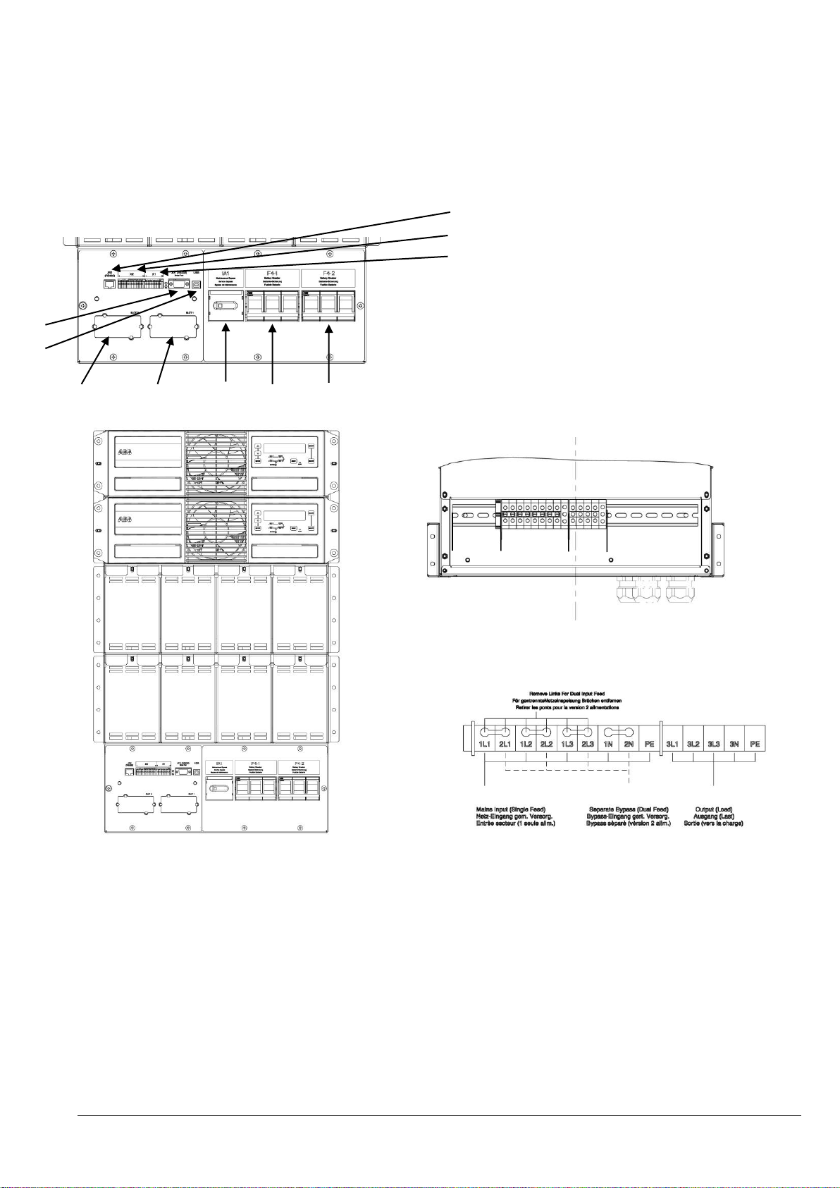
Front side
Rear Side Terminal blocks
Terminal covers and indications
1 Not used JR2 forseen for RJ45 Plug
2 X2 Customer interface on Phoenix Terminals = Potential free contacts
X1 Customer Inputs (detail see Section 3 / 3.1.2 )
3 LED red /green
4 JD1 RS232 / Sub D9/ female, PC interface
5 USB PC Interface
6 SNMP Slot for optional SNMP card ONLY
7 Modem Slot for optional Modem/Ethernet card ONLY
8 Input Bypass terminal for Dual Input feed 16/25 mm2
9 Input Rectifier terminal for Single feed 16/25 mm2
10 Output Load terminal 16/25 mm2
11 F4-1 Battery Circuit Breaker 3x63 A / 800 VDC
12 F4-2 Battery Circuit Breaker 3x63 A / 800 VDC
13 IA1 Maintenance Bypass
Wiring see page 2 section 2.1
1
2
3
4
5
6 7 13 11 12
8+9 10
2.2.5 FRONT VIEW OF DPA UPScale RI 22 AND CONNECTION TERMINALS
Section-2
04-3006_S2_OPM_ABB_DPA_UPSCALE_RI_10-80kW_EN_150316.doc Page 9/14 ABB
Modifications reserved
Page 70
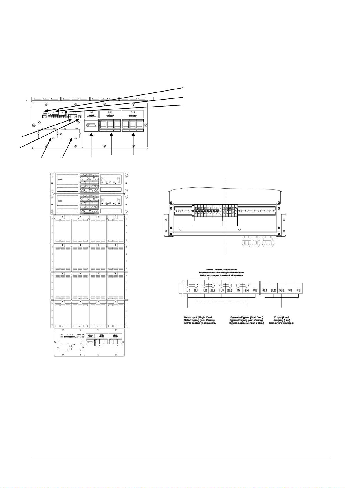
Front side
Rear Side Terminal blocks
Terminal covers and indications
1 Not used JR2 forseen for RJ45 Plug
2 X2 Customer interface on Phoenix Terminals = Potential free contacts
X1 Customer Inputs (detail see Section 3 / 3.1.2 )
3 LED red /green
4 JD1 RS232 / Sub D9/ female, PC interface
5 USB PC Interface
6 SNMP Slot for optional SNMP card ONLY
7 Slot for optional Modem/Ethernet card ONLY
8 Input Bypass terminal for Dual Input feed 16/25 mm2
9 Input Rectifier terminal for Single feed 16/25 mm2
10 Output Load terminal 16/25 mm2
11 F4-1 Battery Circuit Breaker 3x63 A / 800 VDC
12 F4-2 Battery Circuit Breaker 3x63 A / 800 VDC
13 IA1 Maintenance Bypass
Wiring see page 2 section 2.1
4
5
6 7 13 11 12
8+9 10
1
2
3
2.2.6 FRONT VIEW OF DPA UPScale RI 24 AND CONNECTION TERMINALS
Section-2
04-3006_S2_OPM_ABB_DPA_UPSCALE_RI_10-80kW_EN_150316.doc Page 10/14 ABB
Modifications reserved
Page 71
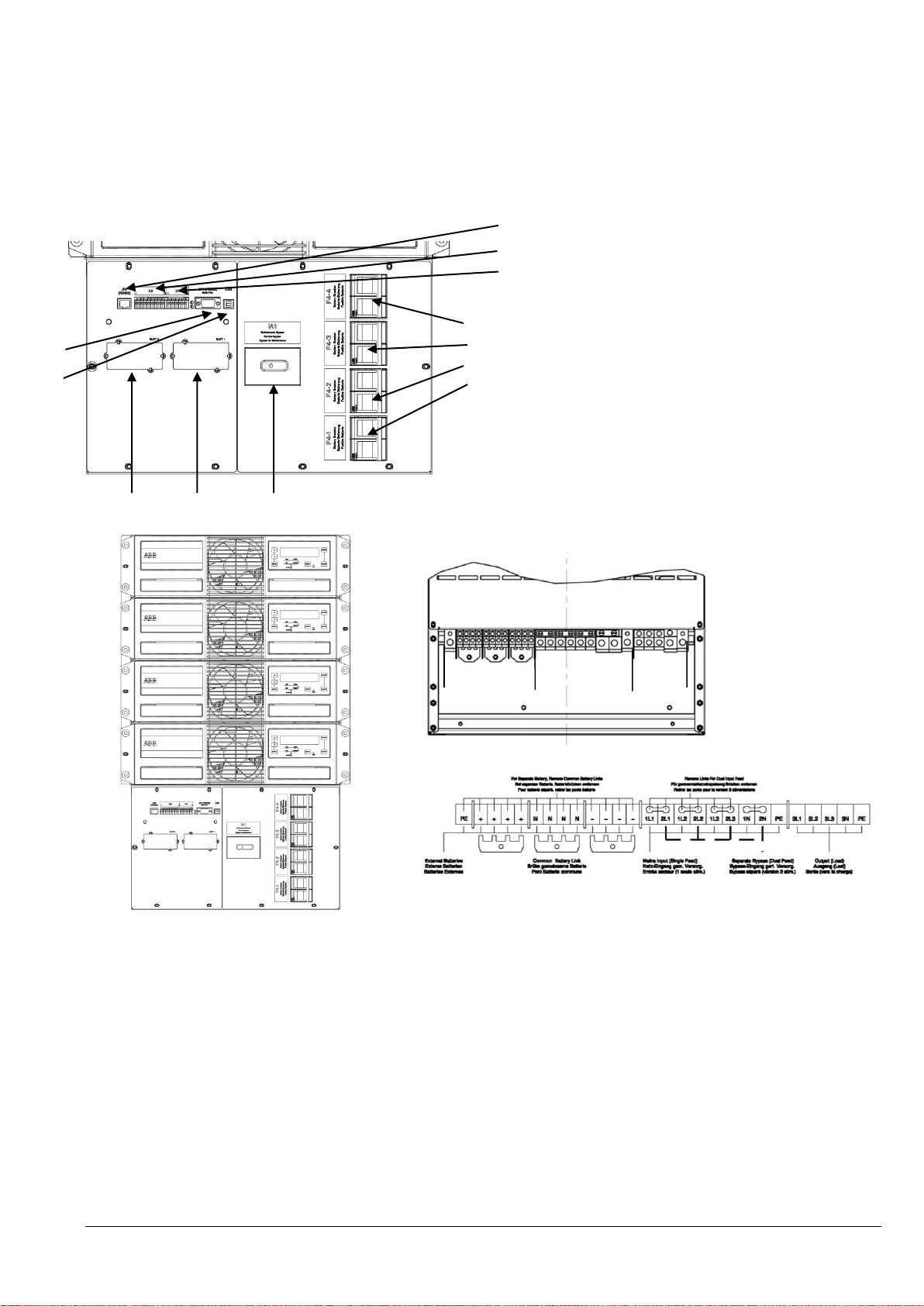
Front side
Rear Side Terminal blocks
Terminal covers and indications
1 Not used JR2 forseen for RJ45 Plug
2 X2 Customer interface on Phoenix Terminals = Potential free contacts
X1 Customer Inputs (detail see Section 3 / 3.1.2 )
3 LED red /green
4 JD1 RS232 / Sub D9/ female, PC interface
5 USB PC Interface
6 SNMP Slot for optional SNMP card ONLY
7 Modem Slot for optional Modem/Ethernet card ONLY
8 Battery terminal + / N / - for Single battery 10/16 mm2
8* Battery terminal + / N / - for Common battery M6
9 Input Bypass terminal for Dual Input feed 50 mm2
10 Input Rectifier terminal for Single feed 50 mm2
11 Output Load terminal 50 mm2
12 F4-1 Battery Circuit Breaker 2x63 A / 800 VDC
13 F4-2 Battery Circuit Breaker 2x63 A / 800 VDC
14 F4-2 Battery Circuit Breaker 2x63 A / 800 VDC
15 F4-2 Battery Circuit Breaker 2x63 A / 800 VDC
16 IA1 Maintenance Bypass
Wiring see page 2 section 2.1
8 /8* 9+10 11
1
2
3
4
5
6 7 16
15
14
13
12
2.2.7 FRONT VIEW OF DPA UPScale RI 40 AND CONNECTION TERMINALS
Section-2
04-3006_S2_OPM_ABB_DPA_UPSCALE_RI_10-80kW_EN_150316.doc Page 11/14 ABB
Modifications reserved
Page 72
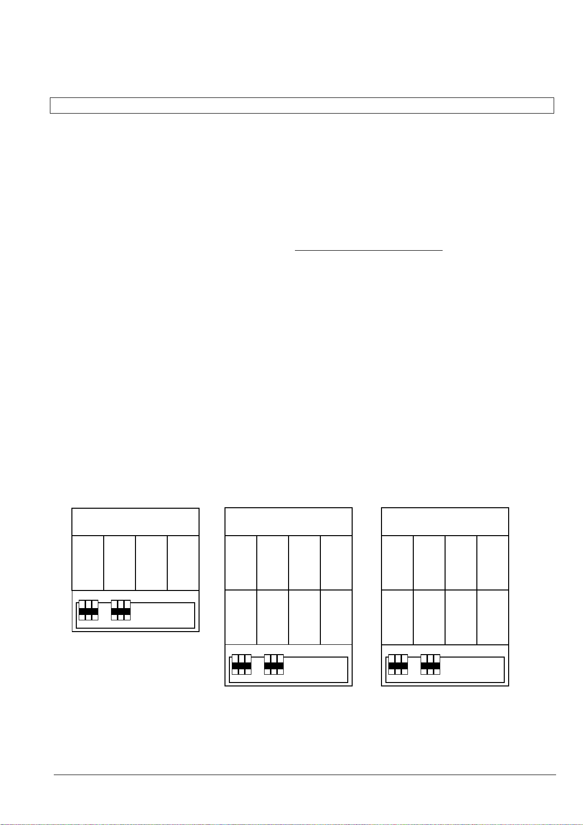
Module
Module
10x7Ah
10x7Ah
10x7Ah
10x7Ah
10x7Ah
10x7Ah
2x5x7Ah
10x7Ah
10x7Ah
10x7Ah
10x7Ah
10x7Ah
10x7Ah
Module
10x7Ah
10x7Ah
10x7Ah
10x7Ah
Section-2
2.3 BATTERY CONNECTIONS
2.3.1 INTERNAL BATTERY MODULES
The followings models have internal battery modules:
DPA UPScale RI11
DPA UPScale RI12
DPA UPScale RI22
DPA UPScale RI24
To achieve a correct cabling of the internal batteries modules, refer to the below drawings which show the various
possible battery configurations and the diagrams in the on the next pages and listed here:
Assembling: S20_0018C Electric Diagram Battery Cabling 2 x(1x50) RI UPScale
Assembling: S20_0019B Electric Diagram Battery Cabling 2 x(1x40) RI UPScale
Assembling: S20_0020C Electric Diagram Battery Cabling 2 x(2x40) RI UPScale
NOTE:
For UPS-Systems DPA UPScale M-10kW, it is allowed to use 20-50 (only even numbers) of 12V-battery blocks
depending the power sourced on the output
For UPS-Systems DPA UPScale M-20kW, it is allowed to use 30-50 (only even numbers) of 12V-battery blocks
depending the power sourced on the output
IMPORTANT : For max. battery autonomies with the corresponding the output power range and no. of battery
blocks per string, refer to Section 10.5 , page 8
NOTE: Set-up the correct number of battery blocks on Control Panel (Menu: Service-Set-Up).
DPA UPScale RI 11 DPA UPScale RI 12 DPA UPScale RI 12
(1x40)x7Ah (1x50)x7Ah (2x40)x7Ah
04-3006_S2_OPM_ABB_DPA_UPSCALE_RI_10-80kW_EN_150316.doc Page 12/14 ABB
Modifications reserved
Page 73
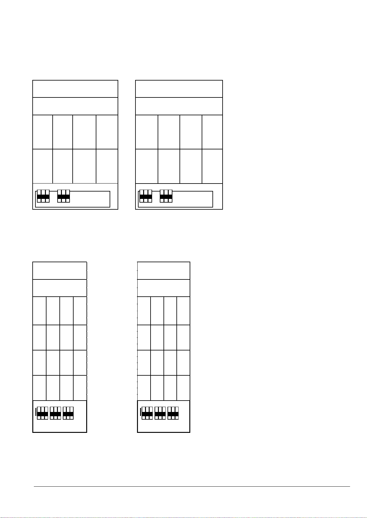
Module
Module
Module
Module
10x7Ah
10x7Ah
10x7Ah
10x7Ah
10x7Ah
10x7Ah
2x5x7Ah
10x7Ah
10x7Ah
10x7Ah
10x7Ah
10x7Ah
10x7Ah
Module
Module
Module
Module
10x7Ah
10x7Ah
10x7Ah
10x7Ah
10x7Ah
10x7Ah
2x5x7Ah
10x7Ah
10x7Ah
10x7Ah
10x7Ah
10x7Ah
10x7Ah 10x7Ah
10x7Ah
10x7Ah
10x7Ah
10x7Ah
10x7Ah
2x5x7Ah
10x7Ah
10x7Ah
10x7Ah
10x7Ah
10x7Ah
10x7Ah
DPA UPScale RI 22 DPA UPScale RI 22
Section-2
(1x50)x7Ah (2x40)x7Ah
DPA UPScale RI 24 DPA UPScale RI 24
2x(1x50)x7Ah 2x(2x40)x7Ah
Other combination possible: refer to Section 10
04-3006_S2_OPM_ABB_DPA_UPSCALE_RI_10-80kW_EN_150316.doc Page 13/14 ABB
Modifications reserved
Page 74
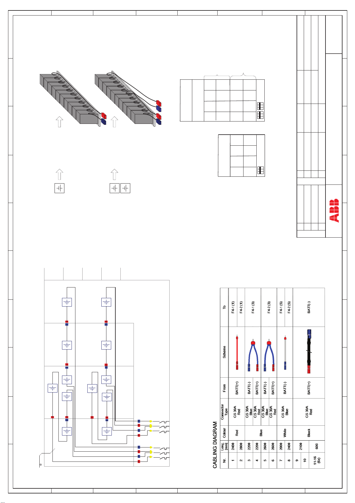
H
G
F
E
D
C
B
A
10 x battery blocks
10x
S20_0024
12V 7Ah
12V 7Ah
MT
Signature :
Signature :
22.10.2009Drawn by :
Date:
10/05/2011 SR
Date:
Checked by :
Signature :
Date:
Replace :
C 24.02.15 MT
10x7Ah
10x7Ah
2x5x7Ah
10x7Ah
F4-1
10x7Ah
10x7Ah
10x7Ah
10x7Ah
2x5x7Ah
10x7Ah
10x7Ah
10x7Ah
2x5x7Ah
10x7Ah
F4-2
F4-1
F4-1
RI 12 RI 24
04-0541 1x(1x50x7Ah) 04-05222x(1x50x7Ah)
F4-2
12V 7Ah
12V 7Ah
S20_0025
2 x 5 x battery blocks
5x
5x
12V 7Ah
12V 7Ah
C
10x7Ah
AB D
C
AB D
S20_0018C
Sheet : 1 of : 1
Battery Cabling 2x(1x50)x7Ah RI Upscale
Modification
678 910
5
D
10x
Modification
4
+
3
+
10x
+
10x
+
5x
+
5x
2
10x
1
+
10x
+
10x
+
5x
+
+
5x
Battery arrangement 2x(1x50) x 7Ah RI
ABC
Wire
1 234
4
H
3x63A
F4-1
6
5
4
3
1
5
3
1
F4-2
E
3x63A
2
6
4
2
(+) (-)(N) (+) (-)(N)
1 2345 678910
D
C
B
A
+
10x
G
+
10x
F
Page 75
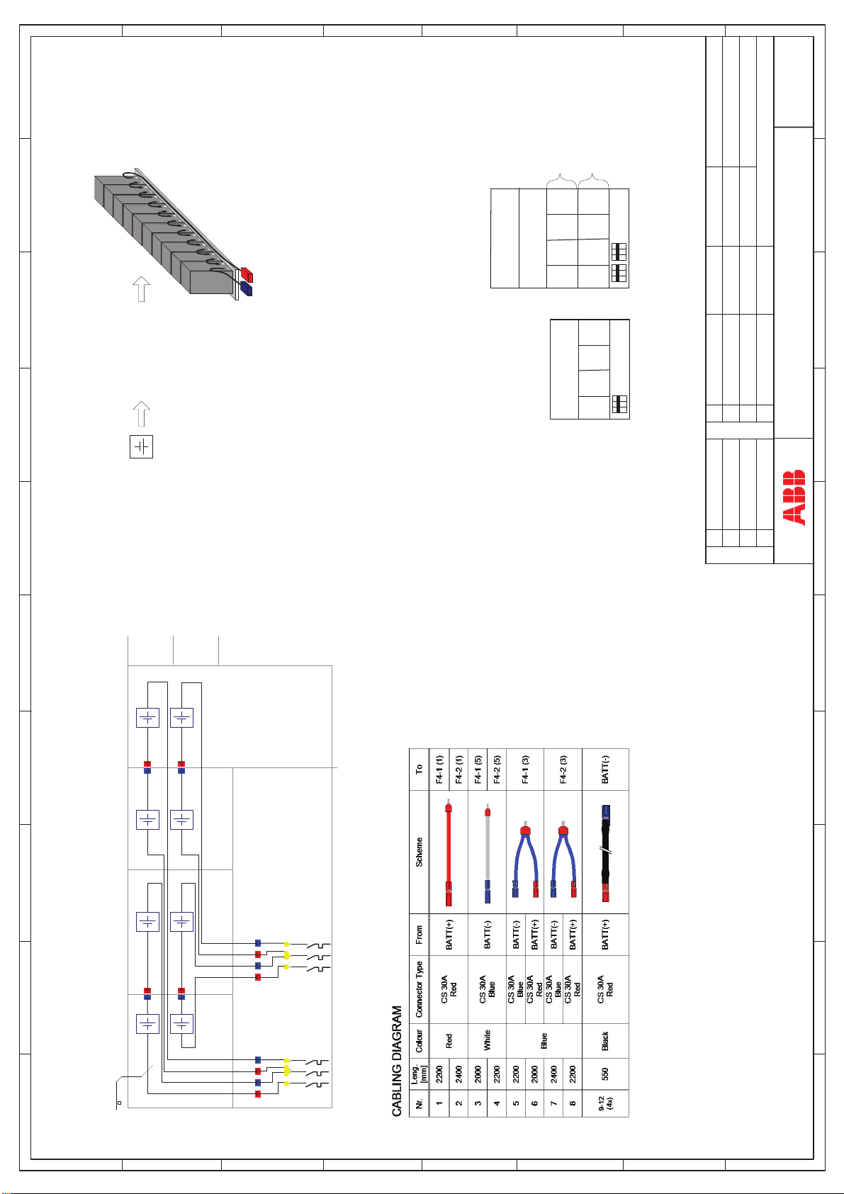
H
G
F
E
D
C
B
A
10 x battery blocks
10x
S20_0024
12V 7Ah
12V 7Ah
MT
Signature :
Signature :
22.10.2009Drawn by :
Date:
Date:
Checked by :
Signature :
Date:
Replace :
F4-1
F4-2
10x7Ah
10x7Ah
10x7Ah
10x7Ah
10x7Ah
10x7Ah
10x7Ah
10x7Ah
10x7Ah
10x7Ah
10x7Ah
10x7Ah
F4-2
F4-1
F4-1
RI 11 RI 22
04-0540 1x(1x40x7Ah) 04-05242x(1x40x7Ah)
C
12V 7Ah
AB D
C
AB D
S20_0019B
Sheet : 1 of : 1
Battery Cabling 2x(1x40)x7Ah RI Upscale
B 24.02.15 MT
Modification
678 910
5
D
2
10x+10x
+
10x
+
10x
Modification
1
+
+
10x
+
10x
6
5
4
3
1
2
Battery arrangement 2x(1x40) x 7Ah RI
1 234
H
ABC
Wire
4
3x63A
F4-1
+
10x
+
10x
5
6
3
4
1
2
(+) (-)(N) (+) (-)(N)
3x63A
F4-2
G
F
E
D
C
B
A
1 2345 678910
Page 76
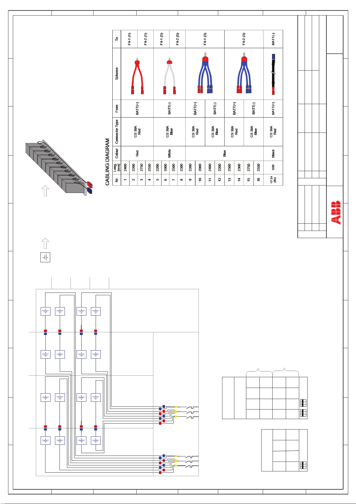
H
G
F
E
D
C
B
A
12V 7Ah
12V 7Ah
Signature :
MT
Signature :
Signature :
S20_0020C
22.10.2009Drawn by :
Date:
Date:
Date:
Sheet : 1 of : 1
Checked by :
Replace :
Battery Cabling 2x(2x40)x7Ah RI Upscale
ROM072/13, SR
C 24.02.15 MT
B
Modification
12V 7Ah
678 910
5
S20_0024
10 x battery blocks
10x
4
10x+10x
+
10x
+
10x
Modification
3
+
+
10x
+
10x
2
10x+10x
10x
10x
1
+
+
+
10x
+
+
10x
6
5
4
3
1
2
C
AB D
(+) (-)(N)
F4-2
10x7Ah
10x7Ah
10x7Ah
10x7Ah
10x7Ah
10x7Ah
10x7Ah
10x7Ah
F4-1
10x7Ah
10x7Ah
10x7Ah
10x7Ah
10x7Ah
10x7Ah
10x7Ah
10x7Ah
F4-2
F4-1
RI 24
04-0543 2x(2x40x7Ah)
Battery arrangement 2x(2x40) x 7Ah RI
ABCD
+
10x
1 234
H
3x63A
F4-1
+
10x
+
10x
G
+
10x
6
5
4
3
2
1
(+) (-)(N)
3x63A
F4-2
F
E
D
C
AB D
C
10x7Ah
10x7Ah
10x7Ah
10x7Ah
B
10x7Ah
10x7Ah
10x7Ah
10x7Ah
F4-1
RI 12
04-0542 1x(2x40x7Ah)
1 2345 678910
A
Page 77

NOTE!
ALL THE OPERATIONS IN THIS MANUAL MUST BE PERFORMED BY CERTIFIED
ELECTRICIANS OR BY QUALIFIED INTERNAL PERSONNEL.
DO NOT OPERATE IN CASE OF PRESENCE OF WATER OR MOISTURE.
BY OPENING OR REMOVING THE UPS-COVERS YOU RUN RISK OF EXPOSURE
TO DANGEROUS VOLTAGES.
!
2.3.2 EXTERNAL BATTERY CABINET AND BATTERY (NOT FORSEEN)
It is normally recommended for redundant systems to provide each UPS with its own separate battery. In this
way the redundancy is extended also to the batteries.
To ensure protection of the personnel during the installation of the UPS make sure that the connections
are performed under the following conditions:
No mains voltage is present in the UPS
All the loads are disconnected
The UPS and the external battery are voltage-free
Section-2
To verify the complete shut down of the DPA UPScale RI perform following steps:
1) Make sure that the fuses feeding the UPS in the input Distribution Board are all open and no power is
fed to the UPS.
2) Make sure the "MAINTENANCE BYPASS"(IA1) is open (position "OFF”)
3) Make sure the battery fuses in the external battery cabinet or racks and on the UPS are open.
To achieve a correct cabling:
=> Refer to chapter 2.2.1 for the DPA UPScale RI 10
=> Refer to chapter 2.2.4 for the DPA UPScale RI 20
=> Refer to chapter 2.2.7 for the DPA UPScale RI 40
1) Connect Earth (PE) between the UPS and external battery cabinet.
2) Connect the corresponding + , N, - terminals between UPS and external battery cabinet according to
drawing
04-3006_S2_OPM_ABB_DPA_UPSCALE_RI_10-80kW_EN_150316.doc Page 14/14 ABB
Modifications reserved
Page 78

Section-3
SECTION-3
3.1 INTERFACING .......................................................................................................................... 2
3.1.1 Customer interface and DRY PORTs (volt-free contacts) ................................................... 3
3.1.1.1 Output Interfaces Terminal blocks X2 (DRY PORTs) .................................................. 3
3.1.1.2 Input Interfaces Terminal blocks X1 ........................................................................... 3
3.1.2 JD1 / RS232 Smart Port Computer Interface .................................................................... 4
3.1.3 USB Computer Interface .................................................................................................... 4
04-3006_S3_OPM_ABB_DPA_UPSCALE_RI_10-80kW_EN_150316.doc Page 1/4 ABB
Modifications reserved
Page 79

3.1 INTERFACING
The UPS cabinet is provided with communication card which provides the system information
Communication card (next to the distribution) :
Input Interfaces X1 (Phoenix terminals)
Output Interfaces : X2 DRY PORTs ,volt-free contacts (Phoenix terminals)
Smart Port JD1 / RS232 Sub D9 / female : Interface (UPS system to computer)
USB Interface (UPS system to computer)
On the Interface board are located two LED’s (3) :
Green LED showing the status of the Interface:
- Fast Blinking: 2 times/sec = Interface is OK
Red LED Board Alarm (indicates a possible replacement of the board)
Section-3
04-3006_S3_OPM_ABB_DPA_UPSCALE_RI_10-80kW_EN_150316.doc Page 2/4 ABB
Modifications reserved
Page 80
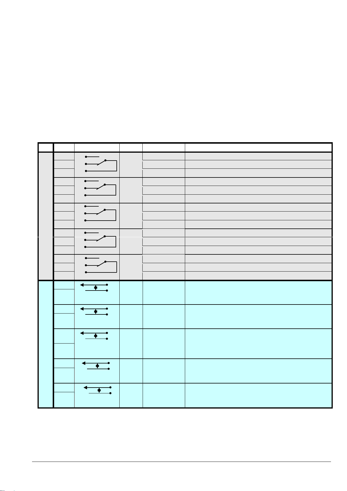
Block
Terminal
Contact
Signal
On Display
Function
X2
X2 / 1
NO
MAINS_OK
Mains Present
X2 / 2
NC
ALARM
Mains Failure
X2 / 3
C
Common
X2 / 4
NO
LOAD_ON_INV
Load on Inverter
X2 / 5
NC
Message
(Load on Mains bypass)
X2 / 6
C
Common
X2 / 7
NO
BATT_LOW
Battery Low
X2 / 8
NC
ALARM
Battery OK
X2 / 9
C
Common
X2 / 10
NO
LOAD_ON_MAINS
Load on bypass (Mains)
X2 / 11
NC
Message
(Load on Inverter)
X2 / 12
C
Common
X2 / 13
NO
COMMON_ALARM
Common Alarm (System)
X2 / 14
NC
ALARM
NO Alarm Condition
X2 / 15
C
Common
X1
X1 / 1
IN
+ 12Vdc
Generator Operation
X1 / 2
GND
GND
(NC = Generator ON)
X1 / 3
IN
+ 12Vdc
Customer IN 1
X1 / 4
GND
GND
(Function on request, to be defined)
X1 / 5
IN
+
3.3Vdc
Temperature Battery
X1 / 6
GND
GND
(If connected , the battery charger current if depending of the battery temp.)
X1 / 7
IN
+ 12Vdc
Remote Shut down
X1 / 8
GND
GND
(Do not remove the factory mounted bridge until external Remote Shut down
is connected)
X1 / 9
IN
+ 12Vdc
12 Vdc sourse
X1 / 10
GND
GND
(max. 200 mA load)
3.1.1 Customer interface and DRY PORTs (volt-free contacts)
All the Input and Output interfaces are connected to Phoenix terminals (cable 0.5 mm2)
3.1.1.1 Output Interfaces Terminal blocks X2 (DRY PORTs)
Provision of signals for the automatic and orderly shutdown of servers, AS400 or Automation building systems
3.1.1.2 Input Interfaces Terminal blocks X1
Connection of Remote Shut down facilities, Generator Operation, Customers specials (see Section 9, chapter 1.2 OPTIONS)
All voltage free contacts are rated 60 VAC max. and 500 mA max.:
Section-3
Phoenix Spring Terminals (X1…X2) Connection
04-3006_S3_OPM_ABB_DPA_UPSCALE_RI_10-80kW_EN_150316.doc Page 3/4 ABB
Modifications reserved
Page 81
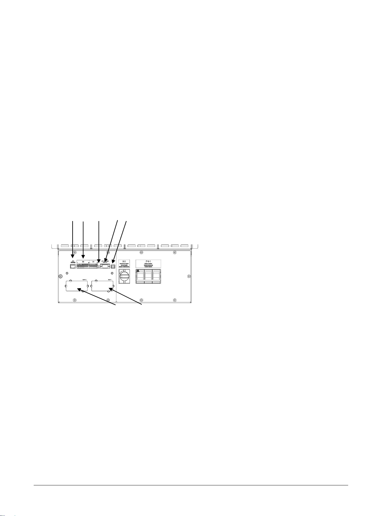
1 JR2 / RS485 (Not used ) foreseen for RJ45 Plug
2 X2 Customer interface on Phoenix Terminals
= Potential free contacts
X1 Customer Inputs
(detail see Section 3 / 1.2 )
3 LED red /green
4 JD1 Smart Port RS232 / Sub D9/ female,
PC interface
5 USB PC Interface
6 SNMP Slot for optional SNMP card ONLY
7 Modem Slot for optional Modem/Ethernet card ONLY
1 2 3
4 5
6 7
Section-3
3.1.2 JD1 / RS232 Smart Port Computer Interface
The Computer Interface JD1 (4) located on the distribution part is an intelligent RS 232 serial port that allows
the UPS system to be connected to a computer. The connector JD1 is a standard D-Type, 9-pin, female.
When installed the Computer Interface, the optional WAVEMON software allows the computer to monitor the
mains voltage and the UPS system status continuously.
In the event of any changes the computer terminal will display a message.
(For details see our optional Monitoring Package: WAVEMON).
3.1.3 USB Computer Interface
The Computer Interface USB (5) located on the distribution part and is in parallel with the intelligent
RS 232 serial port JD1.
When installed the USB Computer Interface trough, the optional WAVEMON software allows the computer to
monitor the mains voltage and the UPS system status continuously.
In the event of any changes the computer terminal will display a message.
(For details see our optional Monitoring Package: WAVEMON).
Example : Distribution Interfaces
04-3006_S3_OPM_ABB_DPA_UPSCALE_RI_10-80kW_EN_150316.doc Page 4/4 ABB
Modifications reserved
Page 82

Section-4
CONTENTS SECTION-4
4.1 OPERATION ............................................................................................................................. 2
4.1.1 Commissioning ................................................................................................................... 2
4.1.2 Control Panel ...................................................................................................................... 2
4.1.2.1 Power Management Display (PMD) ............................................................................. 2
4.1.2.2 LED Indicators ............................................................................................................. 3
4.1.2.3 Keys ............................................................................................................................ 3
4.1.2.4 ON/OFF Start-up and Shutdown Buttons ..................................................................... 3
4.1.3 Description of the LCD ........................................................................................................ 4
4.1.3.1 Status Screens ............................................................................................................ 4
4.1.3.2 Main Menu Screen ....................................................................................................... 4
4.1.3.3 Event Log Screen ........................................................................................................ 5
4.1.3.4 Measurements Screen ................................................................................................. 5
4.1.3.5 Commands Screen ...................................................................................................... 5
4.1.3.6 UPS Data .................................................................................................................... 6
4.1.3.7 Set-Up User ................................................................................................................. 6
4.1.3.8 Set-Up Service ............................................................................................................ 6
4.1.4 Operating Modes ................................................................................................................ 7
4.1.4.1 Mode "ON LINE" (INVERTER MODE) ......................................................................... 7
4.1.4.2 Mode"OFF-LINE"(ECO- or BYPASS MODE) ............................................................... 7
4.1.4.3 "MAINTENANCE BYPASS" - Mode ............................................................................. 8
04-3006_S4_OPM_ABB_DPA_UPSCALE_RI_10-80kW_EN_150316.doc Page 1/8 ABB
Modifications reserved
Page 83
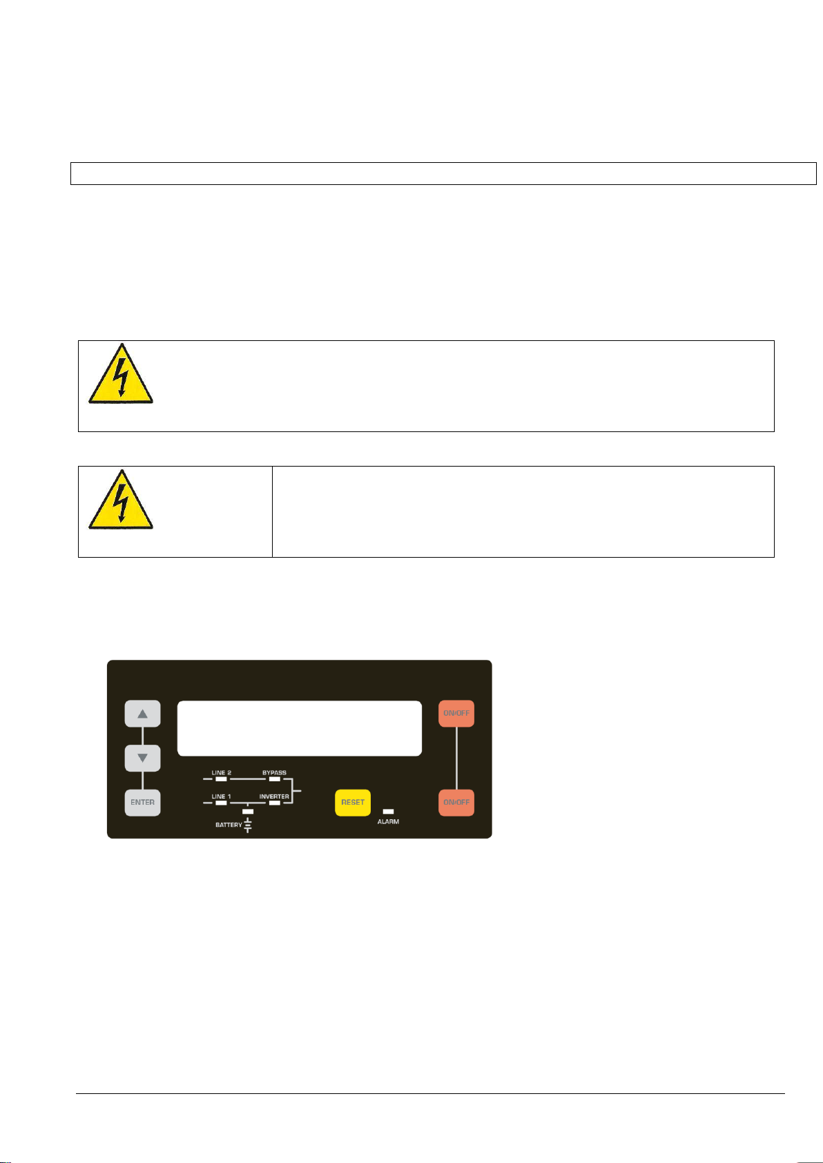
WARNING!
OPERATIONS INSIDE THE UPS MUST BE PERFORMED BY A SERVICE
ENGINEER FROM THE MANUFACTURER OR FROM AN AGENT CERTIFIED BY
THE MANUFACTURER.
WARNING!
ONLY PERSONS WHICH HAVE BEEN TRAINED BY SERVICE TECHNICIANS OF
THE MANUFACTURER OR HIS CERTIFIED SERVICE PARTNERS ARE ALLOWED
TO OPERATE ON THE CONTROL PANEL WITH CLOSED DOORS.
ALL OTHER INTERVENTIONS ON THE UPS SYSTEM HAVE TO BE DONE ONLY
BY SERVICE TECHNICIANS OF THE MANUFACTURER.
Section-4
4.1 OPERATION
4.1.1 Commissioning
The DPA UPScale TM is a high quality electronic machine, that must be commissioned by a fully trained and
certified field service engineer before being put into use.
The commissioning of the UPS involves the connection of the UPS and battery, the checking of the electrical
installation and operating environment of the UPS, the controlled start-up and testing of the UPS and customer
training.
4.1.2 Control Panel
The user-friendly control panel is composed of three parts:
POWER MANAGEMENT LCD DISPLAY (PMD);
LED INDICATORS;
KEYS.
Figure 1.1 Control Panel
4.1.2.1 Power Management Display (PMD)
The 2 x 20 character LCD simplifies the communication with the UPS and provides the necessary monitoring
information about the UPS. The menu driven LCD enables the access to the:
EVENT REGISTER;
Monitor the input and output U, I, f, P,
Battery runtime;
To perform commands like start-up and shut-down of UPS and
Load transfer from INVERTER to BYPASS and vice-versa;
DIAGNOSIS (SERVICE MODE);
Adjustments and testing.
04-3006_S4_OPM_ABB_DPA_UPSCALE_RI_10-80kW_EN_150316.doc Page 2/8 ABB
Modifications reserved
Page 84

INDICATOR
INDICATOR STATUS
MEANING
ALARM
OFF
RED
No alarm condition
Alarm condition
LINE 1
GREEN
RED
Mains rectifier available
Mains rectifier not available
LINE 2
GREEN
RED
OFF
Mains bypass available
Mains bypass not OK or not available
UPS is turned off
BY-PASS
GREEN
OFF
Load on bypass (Bypass-or Eco-Mode)
Bypass not operating (switched-off)
INV
GREEN
RED
OFF
Load on inverter
Inverter fault or load not transferable to inverter
Inverter not operating (switched-off)
BATTERY
GREEN
RED
Flashing GREEN
Battery OK
Battery fault or battery is discharged
Battery in discharge or battery fuse open
KEYS
FUNCTION
ON/OFF
ON/OFF
Serve to switch-on (press both keys simultaneously), or shutdown the UPS (press both keys
simultaneously)
UP ()
Move upwards through the menu
DOWN ()
Move downwards through the menu.
RESET
Cancel the audible alarm. If the alarm condition was only transient the LED-indicator
ALARM would also extinguish otherwise it will remain on (red).
ENTER
Confirms a chosen menu item.
NOTE!
IN THE CASE THAT THE PARALLEL UPS SYSTEM HAS TO BE TURNED
OFF, THEN BOTH ON/OFF BUTTONS ON ALL UPS MODULES HAVE TO
BE PUSHED. IN THIS CASE THE POWER SUPPLY TO THE LOAD WILL
BE INTERRUPTED
4.1.2.2 LED Indicators
The mimic diagram serves to indicate the general status of the UPS. The LED-indicators show the power flow
status and in the event of mains failure or load transfer from inverter to bypass and vice-versa. The
corresponding LED-indicators will change colours from green (normal) to red (warning).
The LED’s LINE 1 (rectifier) and LINE 2 (bypass) indicate the availability of the mains power supply.
The LED’s INVERTER and BYPASS if green indicate which of the two is supplying power to the critical load.
When the battery is supplying the load due to mains failure the LED-indicator BATTERY is flashing.
The LED-indicator ALARM is a visual indication of any internal or external alarm condition. At the same time an
audible alarm will be activated.
Section-4
4.1.2.3 Keys
The keys allow the user to operate the UPS to perform settings and adjustments, to start-up and shutdown the
UPS, to monitor on the LCD display the voltages, currents, frequencies and other values.
4.1.2.4 ON/OFF Start-up and Shutdown Buttons
04-3006_S4_OPM_ABB_DPA_UPSCALE_RI_10-80kW_EN_150316.doc Page 3/8 ABB
Modifications reserved
Page 85

DESCRIPTION
LCD-DISPLAY
1
Load is protected by UPS power.
Load is supplied by inverter (Normal Operation)
and the batteries are connected and o.k.
LOAD
PROTECTED
S
2
Load is not protected by UPS power.
Load is supplied by mains power (load on
bypass) or it is supplied by the inverter (Normal
operation) and the batteries are not o.k.
LOAD
NOT PROTECTED
P1
3
Load not supplied.
UPS is switched off
To start the UPS press the two ON/OFF push
buttons simultaneously
LOAD OFF
SUPPLY FAILURE
P2
4
The UPS is not supplying load anymore.
LOAD DISCONNECTED
P2
DESCRIPTION
LCD-DISPLAY
1
Logging Control. A log of the last 99 events is
stored in the Power Management Display.
EVENT LOG
MEASUREMENTS
2
In Menu Measurements: monitor voltages,
power, frequencies, currents, autonomy etc.
MEASUREMENTS
COMMANDS
3
The Command Menu enables to perform the
commands “Load to inverter”, Load to bypass,
battery test.
COMMANDS
UPS DATA
4
The UPS Data are the UPS personalized
information “serial number”
UPS DATA
SET-UP USER
5
Various settings can be performed by the user:
Date/Time, automatic battery test, etc.
SET-UP USER
SET-UP SERVICE
6
Various adjustments can be performed by the
service staff
SET-UP SERVICE
NO MORE MENU
4.1.3 Description of the LCD
4.1.3.1 Status Screens
Section-4
NOTE: On the right hand side of the LCD there is the indication of single /parallel UPS.
If the UPS is configured as single the indication will be “S”
If the UPS is configured as parallel the indication will be “P” followed by the UPS number
The max no. of module units are 2 per system.
EXEMPLES:
S stands for Single UPS. The system consists of ONLY one UPS
P1 stands for Parallel UPS in a Multi-UPS system and 01 stands for the first Module (MASTER)
in the Multi-UPS system.
P2 stands for Parallel UPS in a Multi-UPS system and 02 stands for the second Module (SLAVE)
in the Multi- UPS system.
The configuration of the single / parallel UPS is achieved in the Menu “SET UP SERVICE”. See Service Manual
section E
4.1.3.2 Main Menu Screen
04-3006_S4_OPM_ABB_DPA_UPSCALE_RI_10-80kW_EN_150316.doc Page 4/8 ABB
Modifications reserved
Page 86

DESCRIPTION
LCD-DISPLAY
1
Battery Runtime
BATT. RUN TIME (MIN)
00h 00m
2
UPS-Output Frequency
OUTPUT FREQUENCY (HZ)
50.00
3
Bypass Frequency.
BYPASS FREQUENCY (HZ)
50.00
4
Battery Voltage
BATTERY VOLTAGE (V)
+ 0.0 - 0.0
5
Battery Charger Current
BATT. CHARGE CUR. (A)
+ 0.0 - 0.0
6
Discharge Current.
DISCHARGE CURRENT (A)
00.00
7
Rectifier Voltage of all three phases
RECTIFIER VOLTAGE (V)
230 230 230
8
Bypass Voltage of all three phases
BYPASS VOLTAGE (V)
230 230 230
9
Output Voltage of all three phases
OUTPUT VOLTAGE (V)
230 230 230
10
Output Current of all three phases
OUTPUT CURRENT (A)
00.00 00.00 00.00
11
Active Output Power of all three phases
ACTIVE POWER (KW)
00.00 00.00 00.00
12
Reactive Output Power of all three phases
REACTIVE POWER (kVAr)
00.00 00.00 00.00
13
Apparent Output Power of all three phases
APPARENT POWER (KVA)
00.00 00.00 00.00
14
Output Power of all three phases
OUTPUT POWER (%)
00.00 00.00 00.00
15
Battery capacity
BATT. CAPACITY (%)
00.00
DESCRIPTION
LCD-DISPLAY
1
Transfer Load to inverter
LOAD TO INVERTER
LOAD TO BYPASS
2
Transfer Load to bypass.
LOAD TO BYPASS
PERFORM BATT.TEST
3
Battery Test
PERFORM BATT.TEST
NO MORE COMMANDS
DESCRIPTION
LCD-DISPLAY
1
Logging Control; a log of the last 99 events is
stored in the Power Management Display.
01 05-10-00
LOAD TO INV.
14-38-59
2
Every stored event is identified with a sequential
number and time stamp.
02 05-10-00
LOAD TO BYP.
14-38-56
3
All events and alarms are indicated with their date
and time of appearance.
03 05-10-00
LOAD OFF
14-37-14
4.1.3.3 Event Log Screen
4.1.3.4 Measurements Screen
Section-4
4.1.3.5 Commands Screen
04-3006_S4_OPM_ABB_DPA_UPSCALE_RI_10-80kW_EN_150316.doc Page 5/8 ABB
Modifications reserved
Page 87

DESCRIPTION
LCD-DISPLAY
1
These general UPS Data are installed at the
manufacturing plant
UPS SERIAL NUMBER
NW-nnnnn
2
Manufacturing date
DATE OF MANUFACTURE
15-01-2009
3
EPROM Version
EPROM VERSION
V-000
4
Actual Date and Time
DATE TIME
dd-mm-yyyy hh:mm:ss
DESCRIPTION
LCD-DISPLAY
1
Set-up Language
(not active yet)
SET LANGUAGE
SET DATE AND TIME
ENGLISH
FRANCAIS
POLISH
2
Set-up Date and Time
SET-UP DATE/TIME
SET-UP BATT. TEST
DD-MM-YY HH-MM-SS
3
Set-up battery test
SET BATTERY TEST
SET GENERATOR OP.
DAY OF MONTH
(1-31)
HOUR OF DAY
(1-24)
REPETITIVE (Y/N)
YES/NO
4
Set-up operation with Gen-Set
SET GENERATOR OP.
NO MORE SETTINGS
BATT.CHARGE LOCK
YES/NO
BYPASS LOCK
YES/NO
DESCRIPTION
LCD-DISPLAY
1
This Menu is reserved for certified service
engineers. It is not to be used by End-Users
SET-UP SERVICE
PASSWORD
2
Type in password
PASSWORD.
4.1.3.6 UPS Data
4.1.3.7 Set-Up User
Section-4
4.1.3.8 Set-Up Service
Password is necessary to enter: Service Manual
04-3006_S4_OPM_ABB_DPA_UPSCALE_RI_10-80kW_EN_150316.doc Page 6/8 ABB
Modifications reserved
Page 88
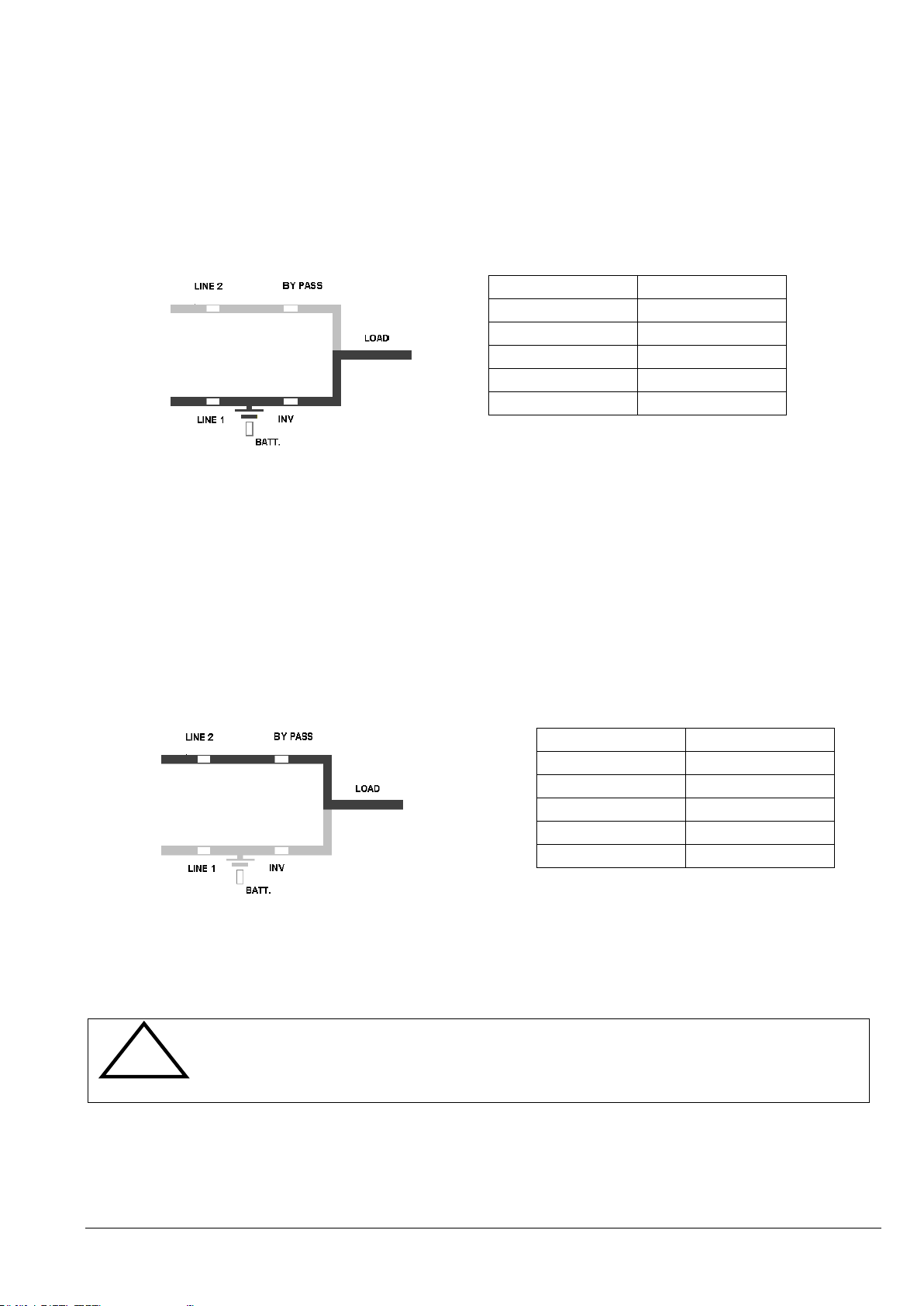
NOTE!
TO HAVE TO MOST ESSENTIAL SECURITY LEVEL, WE RECOMMEND TO
RUN THE UPS ON NORMAL OPERATION MODE, MEANS UPS MODE.
LED Indicator
Colour
LINE 1
Green
LINE 2
Green
BYPASS
OFF
INVERTER
Green
BATTERY
Green
LED Indicator
Colour
LINE 1
Green
LINE 2
Green
BYPASS
Green
INVERTER
OFF
BATTERY
Green
4.1.4 Operating Modes
4.1.4.1 Mode "ON LINE" (INVERTER MODE)
The ON-LINE-Mode is the UPS-Operating Mode in which the load is supplied through the RECTIFIER and
INVERTER.
Using the control panel (see figure 1.1), the UPS can easily be transferred to the ON-LINE-Mode. The ONLINE-Mode provides the highest degree of protection, especially in the event of a mains disturbance or failure.
Section-4
This operating mode is always recommended if the critical loads (computer systems) will not tolerate any
interruption of the supply (not even the shortest).
In the unlikely event of an inverter fault or overload condition the UPS will transfer the load automatically and
without interruption to the static bypass-mains supply (transfer time = 0).
4.1.4.2 Mode"OFF-LINE"(ECO- or BYPASS MODE)
In the "OFF-Line Mode”, the load is supplied from the mains through the static bypass.
Using the control panel (see figure 1.1), the UPS may be easily transferred to "Bypass Mode”.
When the UPS is operating in "Bypass Mode”, the efficiency of the system is higher. In the event of a mains
failure the load will automatically be transferred from mains to inverter within 5 msec (this is valid for single and
parallel systems). The battery charger remains active in the "Bypass-Mode”.
The "Bypass-Mode”, is recommended only if the loads can tolerate interruptions of 3-5 ms (transfer time from
Bypass Mode to ON-LINE Mode).
04-3006_S4_OPM_ABB_DPA_UPSCALE_RI_10-80kW_EN_150316.doc Page 7/8 ABB
Modifications reserved
Page 89
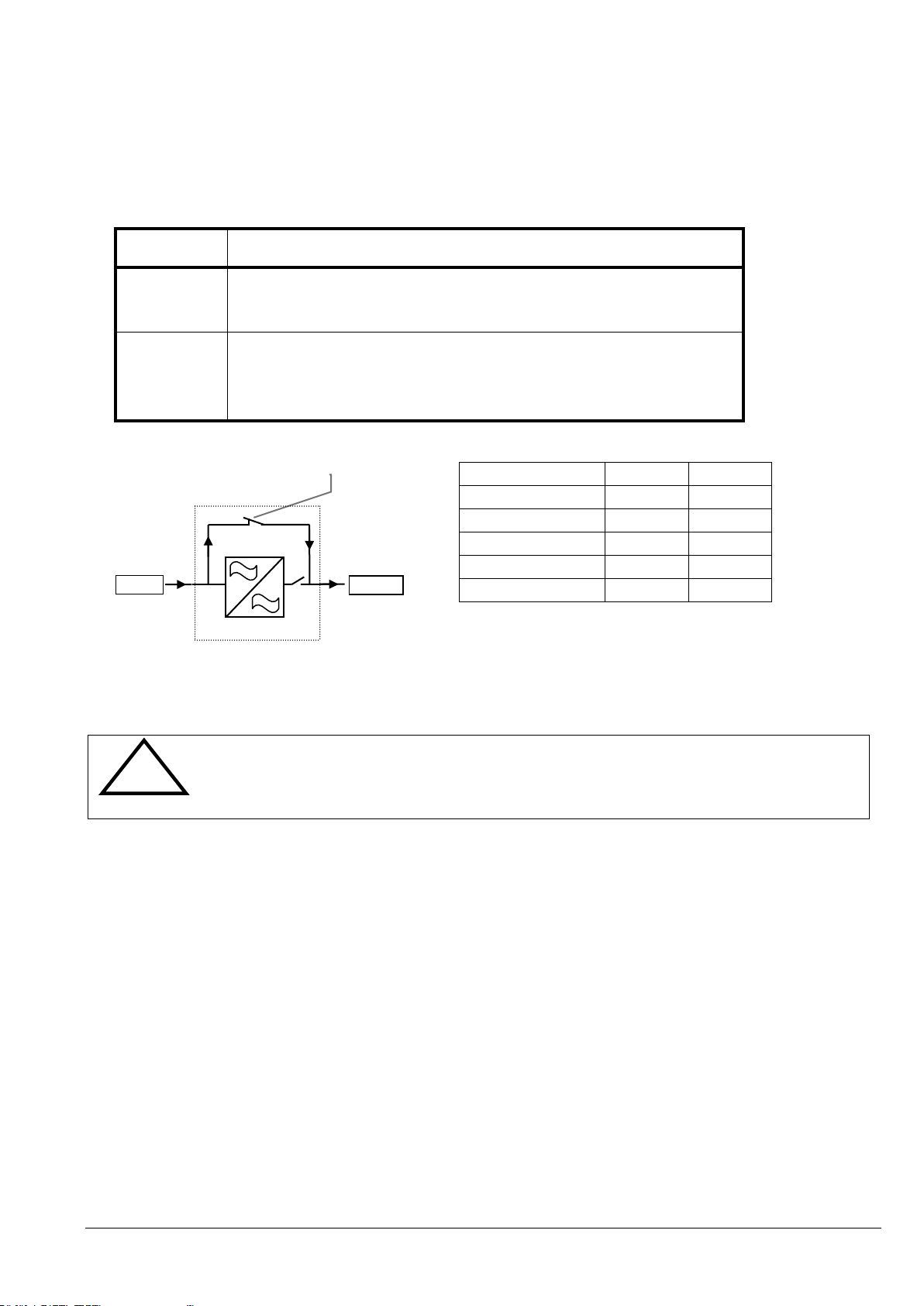
POSITION OF
SWITCH
EFFECT
ON
Bypass-Switch Closed (Load supplied directly from mains)
LCD-indication: “MANUAL BYP IS CLOSED” LED Indicators will indicate
as shown in table below.
OFF
Bypass-Switch Open – Normal operating condition
(Load supplied by inverter)
LCD-indication “MANUAL BYP IS OPEN”
LED Indicators will indicate as shown in table below.
LED Indicator
ON
OFF
LINE 1
Green
Green
LINE 2
Green
Green
BYPASS
Green
OFF
INVERTER
RED
Green
BATTERY
Green
Green
NOTE!
ON OPERATION MODE „MANUAL BYPASS“ THE LOAD IS NOT
PROTECTED AGAINST ANY MAINS FAILURES OR MAINS
DISTURBANCES.
MAINS
LOAD
MAINTENANCE
BYPASS
UPS
4.1.4.3 "MAINTENANCE BYPASS" - Mode
The Maintenance Bypass Mode is performed by means of the IA1 BYPASS SWITCH on the front of the UPS:
Section-4
Before transferring the load to Maintenance Bypass (IA1) always make sure all the UPS-modules are in
the "Bypass-Mode” or “ECO-Mode”.
04-3006_S4_OPM_ABB_DPA_UPSCALE_RI_10-80kW_EN_150316.doc Page 8/8 ABB
Modifications reserved
Page 90

Section-5
CONTENTS SECTION-5
5.1 OPERATION - PROCEDURES ................................................................................................. 2
5.1.1 Start-Up Procedure ............................................................................................................. 2
5.1.2 Shutdown Procedure .......................................................................................................... 4
5.1.3 Load Transfer: from Inverter operation to Maintenance Bypass .......................................... 5
5.1.4 Load Transfer: from Maintenance Bypass to Inverter operations ........................................ 6
5.2 REPLACEMENT OF UPS-MODULE ......................................................................................... 7
5.2.1 Replacement of UPS-Module in Single-Module Systems .................................................... 7
5.2.1.1 How to Extract a UPS-Module in SINGLE MODULE Systems ..................................... 7
5.2.1.2 How to Fit Back a UPS-Module in SINGLE-MODULE-Systems ................................... 8
5.2.2 Replacement of UPS-Module in Redundant Multi-Module System .................................... 10
5.2.2.1 How to Extract a Module in Redundant Multi-Module System .................................... 10
5.2.2.2 How to insert a module in a Redundant Multi Module System .................................... 10
5.2.3 Replacement of a Module in Capacity Multi-Module System ............................................. 12
5.2.3.1 How to Extract a Module in a Capacity Multi-Module System..................................... 12
5.2.3.2 How to Fit Back a Module in a Capacity Multi-Module System ................................... 13
04-3006_S5_OPM_ABB_DPA_UPSCALE_RI_10-80kW_EN_150316.doc Page 1/14 ABB
Modifications reserved
Page 91
WARNING!
THE OPERATIONS DESCRIBED IN THIS CHAPTER MUST BE
PERFORMED BY A SERVICE ENGINEER FROM THE MANUFACTURER OR
FROM A AGENT CERTIFIED BY THE MANUFACTURER.
LED Indicator
Colour
LINE 1
Green
LINE 2
Green
BYPASS
Green
INVERTER
OFF
BATTERY
Flashing Green
LED Indicator
Colour
LINE 1
Green
LINE 2
Green
BYPASS
OFF
INVERTER
Green
BATTERY
Flashing Green
5.1 OPERATION - PROCEDURES
5.1.1 Start-Up Procedure
Situation of UPS-System before switching it on:
1. Make sure the fuses for the supply of UPS-System in the Input Distribution Board on site are open.
2. Make sure all the input and output cabling has been performed correctly and check the input phase
rotation.
3. Verify that the Maintenance Switch IA1 is open and in Position OFF.
4. Make sure all the internal battery fuses in the UPS (if any) and the external battery cabinets are open.
Start up procedure of DPA UPScaleTM:
Section-5
1. Insert fuses for the supply of UPS-System in the Input Distribution
- The LED-indicators LINE 1 and battery on UPS-Module is lit – green
- On LCD-Display “LOAD OFF, SUPPLY FAILURE” will appear.
2. UPS-Module 1:
Press both “ON/OFF” Main Buttons to switch on UPS.
LED-indicator will appear as shown below:
3. Check Command: LOAD TO INVERTER
LED indicator will appear as shown below:
4. Scroll through the menu measurement and check their correctness
5. Module 2: Repeat same procedure as for Module 1:Steps 2)-4).
6. Check battery polarity and voltage.
7. If the battery polarity and voltage is correct insert internal (if any) and external battery fuses
(breakers).
04-3006_S5_OPM_ABB_DPA_UPSCALE_RI_10-80kW_EN_150316.doc Page 2/14 ABB
Modifications reserved
Page 92

LED Indicator
Colour
LINE 1
Green
LINE 2
Green
BYPASS
Green
INVERTER
RED
BATTERY
Green
Section-5
8. Testing of Parallel Functions
(The load fuses in output Distribution Board are still open i.e. the loads are disconnected!).
All UPS-Modules are on INVETER MODE
9. Press simultaneously the two ON/OFF buttons on the UPS-control panel (PMD) on all control panels
on the module to turn the modules OFF. On the LCD’s message “LOAD OFF, SUPPLY FAILURE”
will appear
10. Press simultaneously the two ON/OFF buttons on the UPS-control panel (PMD) on all control panels
on the modules to turn the modules ON. On output Terminal Block there is now UPS power and on
all LCD’s: “LOAD PROTECTED” will appear.
11. Load transfer to Maintenance Bypass
Go to Menu COMMANDS and choose command “LOAD TO BYPASS” and transfer the load to mains on
control panel of any one of the UPS-modules.
Close Maintenance Bypass Switch IA1 (position ON)
On LCD: “MANUAL BYP IS CLOSED” will appear and the LED-indicator will indicate as shown below:
12. Connect Load to the UPS Output
Insert fuses in output Distribution Board
Verify on control Panel that the load is on bypass
13. Open Maintenance Bypass Switch IA1
On LCD: “MANUAL BYP IS OPEN” will appear followed by “LOAD NOT PROTECTED”
14. Check on LCD the Output Powers, Voltages Currents and Frequencies.
15. Load transfer to Inverter
Go to Menu COMMANDS and choose command “LOAD TO INVERTER” and transfer the load to
inverter on control panel of any one of the three UPS-modules.
On all LCD’s: “LOAD PROTECTED” will appear followed by
16. Check the output Voltages and Currents once again.
THE LOAD IS NOW PROTECTED BY THE DPA UPScaleTM
04-3006_S5_OPM_ABB_DPA_UPSCALE_RI_10-80kW_EN_150316.doc Page 3/14 ABB
Modifications reserved
Page 93
WARNING!
THE OPERATIONS DESCRIBED IN THIS CHAPTER MUST BE
PERFORMED BY A SERVICE ENGINEER FROM THE MANUFACTURER OR
FROM A AGENT CERTIFIED BY THE MANUFACTURER.
NOTE!
IN THE CASE THAT THE PARALLEL UPS SYSTEM HAS TO BE TURNED
OFF, THEN BOTH ON/OFF BUTTONS ON ALL UPS MODULES HAVE TO
BE PUSHED. IN THIS CASE THE POWER SUPPLY TO THE LOAD WILL BE
INTERRUPTED.
LED Indicator
Colour
LINE 1
Green
LINE 2
OFF
BYPASS
OFF
INVERTER
OFF
BATTERY
Green
NOTE!
MAKE SURE THE INTERNAL DC-CAPACITORS (ELCO) HAVE BEEN
DISCHARGED WAITING AT LEAST 2 MINUTES.
Section-5
5.1.2 Shutdown Procedure
The DPA UPScaleTM may be shutdown completely, if the load does not need input power for an extended period of
time.
It may be switched to Maintenance Bypass Mode for service or maintenance purposes, or transferred to the OFFLINE Mode (ECO-Mode), if the load does not need the highest degree of protection.
The load may be disconnected by means of the two ON/OFF (LOAD-OFF) buttons for security reasons.
Complete Shutdown procedure of DPA UPScale TM:
Only in case there is no need to supply the load, the UPS System can be completely shutdown. The following
procedures can only be executed after the load has completely been de-energized.
1. Verify that the loads are shutdown and that there is no need for power supply to the load.
2. If the loads are all disconnected, press simultaneously both ON/OFF-Buttons on UPS-Control Panel
on all control Panels on each module.
On the LCD: “LOAD OFF, SUPPLY FAILURE” will appear and the LED-indicator will indicate as
shown below:
3. Open battery fuses/breakers on internal (if any) and external battery cabinets or racks.
4. Open the mains fuses/breaker in the building distribution panel.
THE DPA UPAScaleTM IS NOW VOLTAGE FREE.
04-3006_S5_OPM_ABB_DPA_UPSCALE_RI_10-80kW_EN_150316.doc Page 4/14 ABB
Modifications reserved
Page 94
WARNING!
THE OPERATIONS DESCRIBED IN THIS CHAPTER MUST BE
PERFORMED BY A SERVICE ENGINEER FROM THE MANUFACTURER OR
FROM A AGENT CERTIFIED BY THE MANUFACTURER.
LED Indicator
Colour
LINE 1
Green
LINE 2
Green
BYPASS
Green
INVERTER
RED
BATTERY
Green
LED Indicator
Colour
LINE 1
Green
LINE 2
OFF
BYPASS
OFF
INVERTER
OFF
BATTERY
Flashing Green
NOTE!
THE UPS SYSTEM IS STILL POWERED (DANGEROUS VOLTAGE).
NOTE!
THE LOAD IS NOW SUPPLIED BY MAINS AND IS THEREFORE NOT
PROTECTED THROUGH THE UPS.
Section-5
5.1.3 Load Transfer: from Inverter operation to Maintenance Bypass
If it is necessary to perform service or maintenance on the UPS it is possible to transfer the UPS to
MAINTENANCE BYPASS.
Situation of UPS-System before starting the Transfer Procedure to Maintenance Bypass:
The load is protected by DPA UPScale ST running in normal operation. (The UPS-Module is operating on inverter).
1. Using LCD panel, select the COMMANDS menu and choose command “LOAD TO BYPASS” and
transfer the load to mains on control panel of any one of the UPS-modules
On LCD panel “LOAD NOT PROTECTED” will appear.
2. Close Maintenance Bypass Switch IA1 (position ON).
On LCD: “MANUAL BYP IS CLOSED” will appear and the mimic panel will show:
3. Press simultaneously the two ON/OFF buttons on the UPS-control panel (PMD) on all control panels
on the modules.
On the LCD’s message “LOAD OFF, SUPPLY FAILURE” will appear and the mimic panel will show:
4. Open battery fuses/breakers on the internal (if any) and the external battery cabinets or racks.
04-3006_S5_OPM_ABB_DPA_UPSCALE_RI_10-80kW_EN_150316.doc Page 5/14 ABB
Modifications reserved
Page 95
WARNING!
THE OPERATIONS DESCRIBED IN THIS CHAPTER MUST BE
PERFORMED BY A SERVICE ENGINEER FROM THE MANUFACTURER OR
FROM A AGENT CERTIFIED BY THE MANUFACTURER.
LED Indicator
Colour
LINE 1
Green
LINE 2
OFF
BYPASS
OFF
INVERTER
OFF
BATTERY
Flashing/Green
LED Indicator
Colour
LINE 1
Green
LINE 2
Green
BYPASS
Green
INVERTER
RED
BATTERY
Green
Section-5
5.1.4 Load Transfer: from Maintenance Bypass to Inverter operations
This procedure describes the sequence of operations to be done in order to restart the UPS and restore ON-LINE
mode (Load on Inverter).
Situation of UPS-System before starting the Transfer Procedure to ON-LINE mode:
The load is supplied directly by Input Mains power and the UPS is OFF.
1. Close battery fuses/breakers in the external battery cabinets or racks.
2. On the LCD’s: “LOAD OFF, SUPPLY FAILURE” will appear and the mimic panel will show:
3. Press simultaneously the two ON/OFF buttons on the UPS-control panel (PMD) on all control panels
of the modules.
Unit will start-up and after about 60 seconds the mimic panel will show:
4. Make sure that the bypass LED is green, then open the Maintenance Bypass Switch IA1 (position
OFF).
5. Using LCD panel, select the COMMANDS menu and choose command “LOAD TO INVERTER”. This
will transfer the LOAD to Inverter on the complete system (all units). On LCD panel “LOAD
PROTECTED” will appear.
THE LOAD IS NOW SUPPLIED BY INVERTER POWER AND IS PROTECTED
04-3006_S5_OPM_ABB_DPA_UPSCALE_RI_10-80kW_EN_150316.doc Page 6/14 ABB
Modifications reserved
Page 96
WARNING!
THE OPERATIONS DESCRIBED IN THIS CHAPTER MUST BE
PERFORMED BY A SERVICE ENGINEER FROM THE MANUFACTURER OR
FROM A AGENT CERTIFIED BY THE MANUFACTURER.
WARNING!
The weight of a UPS module can reach 22kg, therefore it can be lifted by 1
person. We recommend two persons for carrying the module .
Potential dangers:
the ups module due to its weight, if removed inappropriately, can cause
serious injury or damage should the module fall down.
note:
we recommend that the modules are handled by two persons.
SUITABLE LIFTING TOOLS RESPECTIVELY SAFEGUARD PLATFORMS
AGAINST EVT. FALL DOWN ARE TO BE PLANNED.
LED Indicator
Colour
LINE 1
Green
LINE 2
Green
BYPASS
Green
INVERTER
RED
BATTERY
Green
5.2 REPLACEMENT OF UPS-MODULE
5.2.1 Replacement of UPS-Module in Single-Module Systems
5.2.1.1 How to Extract a UPS-Module in SINGLE MODULE Systems
Section-5
If your DPA UPScaleTM consists of only one single UPS-Module then perform following steps to extract the module:
1. Reset the Alarm on faulty Module. The audible noise will stop.
If the Alarm condition persists (the LED-Indicator ALARM will remain red) it means that there is a fault
in the UPS-Module.
2. If the load is supplied by the mains in Bypass-Mode (Eco-Mode) the Maintenance Bypass (IA1) may
be closed by turning it to position “ON”.
NOTE: If the load is on inverter, then before closing the Maintenance Bypass IA1, transfer load to
bypass by means of the command “LOAD TO BYPASS” in submenu COMMANDS. On LCD: “LOAD
NOT PROTECTED” will appear.
3. Close Maintenance Bypass Switch IA1 (position ON)
On LCD: “MANUAL BYP IS CLOSED” will appear and the LED-indicator will indicate as shown
below:
The load is now directly supplied by mains and is not protected
04-3006_S5_OPM_ABB_DPA_UPSCALE_RI_10-80kW_EN_150316.doc Page 7/14 ABB
Modifications reserved
Page 97
NOTE!
THE LOAD IS NOW DIRECTLY SUPPLIED BY MAINS AND IS NOT
PROTECTED.
WARNING!
THE LOAD IS NOW DIRECTLY SUPPLIED BY MAINS AND IS NOT
PROTECTED.
WARNING!
BEFORE DRAWING THE UPS-MODULE COMPLETELY OUT, WAIT 5
MINUTES UNTIL THE INTERNAL DC-CAPACITORS ARE DISCHARGED.
!
Section-5
4. Press both ON/OFF Buttons on UPS-Module simultaneously;
5. Open battery fuses/breakers on the internal (if any) and the external battery cabinet or rack;
6. Unscrew the two screws on the front side of the module that are fixing it to the UPS-frame;
7. Pull Module only partly horizontally by means of the 2 handles until the rear connectors are
disconnected.
8. Draw UPS-Module by pulling it out horizontally:
NOTE: We recommend 2 persons for pulling out the module from the UPS-Frame. The weight of a
of UPScale M10 is 18.5 kg, M20 module is 21.5kg)
9. Insert new UPS-Module or cover the opening (UPS-Module Compartment) with appropriate
protection cover immediately and fix with two screws.
WHILE THE UPS IS OPERATING IN THE MAINTENANCE BYPASS-MODE THE LOAD IS NOT PROTECTED
AND IN THE EVENT OF A MAINS FAILURE THE LOAD SUPPLY WILL BE INTERRUPTED AND THE LOAD
WILL CRASH.
5.2.1.2 How to Fit Back a UPS-Module in SINGLE-MODULE-Systems
If your DPA UPScaleTM consists of only one single UPS-Module then perform following steps to fit back the
new module:
1. Remove UPS-Module compartment protection cover by unscrewing two screws on the front.
2. Slide two thirds of UPS-Module into dedicated UPS-compartment (make sure not to plug the UPSModule into the rear connector).
Push UPS-module to its final position and push strongly to assure good contact on the rear plugs.
NOTE: We recommend 2 persons for pulling out the module from the UPS-Frame. The weight of a
of UPScale M10 is 18.5 kg, M20 module is 21.5kg)
3. Tighten the two screws on the front of module.
04-3006_S5_OPM_ABB_DPA_UPSCALE_RI_10-80kW_EN_150316.doc Page 8/14 ABB
Modifications reserved
Page 98

LED Indicator
Colour
LINE 1
Green
LINE 2
Green
BYPASS
Green
INVERTER
RED
BATTERY
Green
Section-5
4. Check if the LED LINE1 and battery is green. If yes, mains voltage is OK;
5. Close internal and external battery fuses/breaker (if available);
6. Press simultaneously both “ON/OFF” Buttons to start-up UPS.
LCD panel must display: LED-indicator will appear as shown below:
7. Open Maintenance Bypass (IA1) by turning it to position “OFF”. The load is now supplied by the static
bypass.
8. Transfer load to mains and inverter for testing using submenu COMMANDS
9. Transfer load to Inverter-Mode by means of COMMAND “LOAD TO INVERTER”. On LCD: “LOAD
PROTECTED” will appear.
THE LOAD IS NOW PROTECTED BY DPA UPSCALE™ RI
04-3006_S5_OPM_ABB_DPA_UPSCALE_RI_10-80kW_EN_150316.doc Page 9/14 ABB
Modifications reserved
Page 99
WARNING!
THE WEIGHT OF A UPS MODULE CAN REACH 22KG, THEREFORE IT IS
RECOMMENDED TO BE LIFTED BY 2 PERSONS. THE MODULE SHALL
NEVER BE CARRIED BY ONE PERSON ONLY.
WARNING!
MAKE SURE THE INTERNAL DC-CAPACITORS (ELCO) HAVE BEEN
DISCHARGED WAITING AT LEAST 5 MINUTES. HOW TO EXTRACT A
MODULE IN REDUNDANT MULTI-MODULE SYSTEM
LED Indicator
Colour
LINE 1
Green
LINE 2
OFF
BYPASS
OFF
INVERTER
OFF
BATTERY
Flashing Green
WARNING!
THE WEIGHT OF A UPS MODULE CAN REACH 22KG, THEREFORE IT IS
RECOMMENDED TO BE LIFTED BY 2 PERSONS. THE MODULE SHALL
NEVER BE CARRIED BY ONE PERSON ONLY
5.2.2 Replacement of UPS-Module in Redundant Multi-Module System
5.2.2.1 How to Extract a Module in Redundant Multi-Module System
If in a redundant parallel system a UPS-module is faulty, the load will continue to be protected by the operating
modules On-Line-Mode (Inverter-Mode) and the faulty Module may be replaced without having to transfer the
load to bypass!
To extract the faulty module from the UPS-Frame in a Redundant Multi- Module Configuration proceed as
follows:
1. Identify the faulty Module with the Alarm condition and RESET the Alarm. The audible noise will stop.
If the Alarm conditions persists (the LED-Indicator ALARM is red) there is a fault in the UPS-Module.
Section-5
2. Verify that load is supplied by inverter of the other modules running by checking the LCD indication
LOAD PROTECTED. Verify load measures on the operating modules.
3. Turn the faulty module OFF by pressing simultaneously both “ON/OFF” buttons.
On the LCD: “LOAD OFF, SUPPLY FAILURE” should appear and the LED-indicator will indicate as
shown below:
4. Remove the two fixation screws and slide out the UPS-Module (10cm)
This operation will disconnect module by the power connection located on the back of the cabin.
5. Pull the module out.
ATTENTION: BEFORE DRAWING THE UPS-MODULE COMPLETELY OUT, WAIT 5 MINUTES UNTIL
THE INTERNAL DC-CAPACITORS ARE DISCHARGED.
NOTE: We recommend 2 persons for pulling out the module from the UPS-Frame. The weight of a
of UPScale M10 is 18.5 kg, M20 module is 21.5kg)
6. Screw the protection cover on the empty area left empty by the module with the two fixation screws.
5.2.2.2 How to insert a module in a Redundant Multi Module System
04-3006_S5_OPM_ABB_DPA_UPSCALE_RI_10-80kW_EN_150316.doc Page 10/14 ABB
Modifications reserved
Page 100

LED Indicator
Colour
LINE 1
Green
LINE 2
OFF
BYPASS
OFF
INVERTER
OFF
BATTERY
Flashing Green
In a Redundant Parallel system one module can be re-introduced on its original location without affecting
normal system operation. Load will be protected by the other modules running ON-LINE.
Module must be previously set according to system personalization. Please make sure with your nearest
service centre for correct settings.
1. Remove the protection cover by unscrewing the two fixation screws on the front.
2. Lift the module to its destination position. See above note concerning weights.
3. Slide two thirds of UPS module into dedicated compartment (make sure not to plug the UPS-Module into
the rear connector).
Push UPS-module to its final position and push strongly to assure good contact on the rear plugs.
Tighten the two screws on the front of module;
4. Check if LED LINE1 and battery is green. If yes, mains voltage is OK;
On the LCD: “LOAD OFF, SUPPLY FAILURE” will appear and the LED-indicator will indicate as
shown below:
Section-5
5. Close internal and/or external battery fuses/breaker of the new Module
6. Press both “ON/OFF” Buttons simultaneously to start-up UPS.
7. Module will restart automatically connecting load to inverter and run in parallel with other ON LINE
modules. LCD panel must show LOAD PROTECTED indication.
THE LOAD IS NOW PROTECTED BY THE DPA UPScaleTM
04-3006_S5_OPM_ABB_DPA_UPSCALE_RI_10-80kW_EN_150316.doc Page 11/14 ABB
Modifications reserved
 Loading...