

ABB Disconnect switches Accessories Catalog
Disconnect
switches
19
19 - Disconnect switches
1111
1111
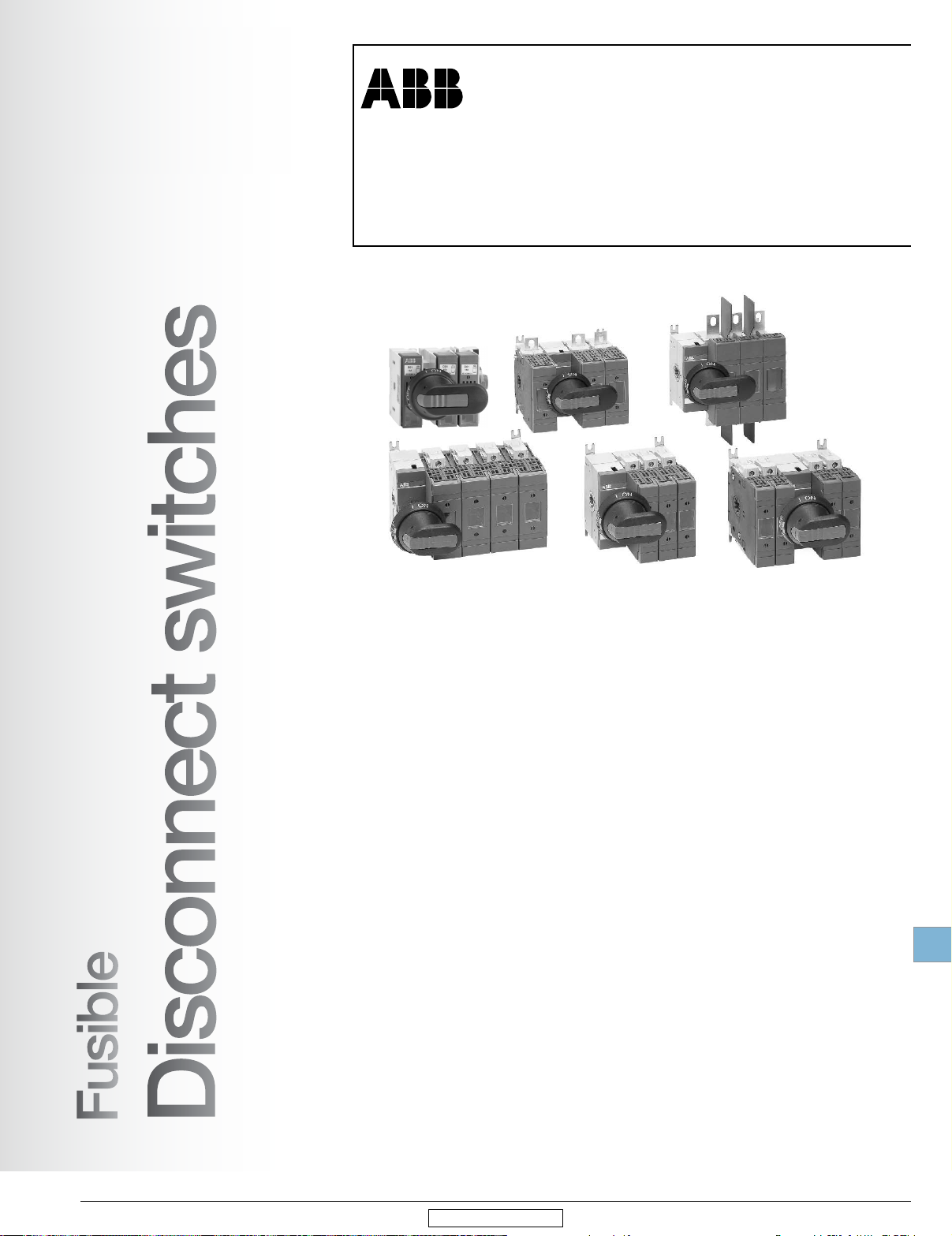
Disconnect switches
Index
Non-fusible and fusible disconnect switches ..........19.1 - 19.6
General information
Versatility, broad range, compact size
International acceptance, installation options, broad range of accessories
Mounting, mounting positions, incoming power feeds, terminal connections
Finger proof, door interlock, padlockable, positive opening operation ...............................19.4
Welded contact protection, clear position indication, visible blades, constant control .......19.5
High performance, superior short circuit protection, fuse isolation ....................................19.6
...............................................................................19.1
.......................19.2
....................19.3
Non-fusible disconnect switches ...........................19.7 - 19.18
Approvals and ratings ...............................................................................................................19.7
Ordering details guide .....................................................................................................19.8 - 19.9
Ordering details information
Base and DIN rail mounted, 16 - 2000 A .................................................................................19.11
Door mounted, 16 - 100 A.......................................................................................................19.12
Side operated
Flange & double throw (change-over)..........................................................................19.14 - 19.17
OTDC Solar Disconnect switches ...........................................................................................19.18
.........................................................................................................................19.13
....................................................................................................19.10
Fusible disconnect switches ................................19.19 - 19.28
Approvals and ratings .............................................................................................................19.19
Ordering details guide
Ordering details information
Base & DIN rail mounted.........................................................................................................19.22
Side operated and flange ...........................................................................................19.23 - 19.26
High speed fuse pattern .............................................................................................19.27 - 19.28
.............................................................................................................19.20
....................................................................................................19.21
Accessories ...........................................................19.29 - 19.40
Standard handles & shafts ..........................................................................................19.30 - 19.32
Auxiliary contacts
Terminal lugs...........................................................................................................................19.34
Terminal shrouds ....................................................................................................................19.35
Additional poles ......................................................................................................................19.36
Fuse monitors & carriers .........................................................................................................19.37
Miscellaneous accessories & replacement parts .....................................................................19.38
Conversion, transfer & bypass mechanisms............................................................................19.39
....................................................................................................................19.33
Enclosed disconnect switches .............................19.41 - 19.48
General information ....................................................................................................19.42 - 19.44
Non-fusible
3 pole, 16 - 3150 A ...........................................................................................................19.45
6 pole, 16 - 1200 A ...........................................................................................................19.46
Fusible
3 pole, 30 - 800 A .............................................................................................................19.47
Accessories ............................................................................................................................19.48
Technical data ........................................................19.49 - 19.66
Technical data ............................................................................................................19.49 - 19.59
Auxiliary contact timing diagrams
NEMA Environmental ratings ......................................................................................19.64 - 19.65
Definition ...............................................................................................................................19.66
................................................................................19.60 - 19.63
Approximate dimensions ......................................19.67 - 19.91
Low Voltage Products & Systems 19.A
ABB Inc. • 888-385-1221 • www.abb.us/lowvoltage
1SXU000023C0202 Rev. B

Disconnect
switches
19
Notes
19.B Low Voltage Products & Systems
1SXU000023C0202 Rev. B
Revised January 2015 Revised January 2014
ABB Inc. • 888-385-1221 • www.abb.us/lowvoltage
......
--
••
.-~
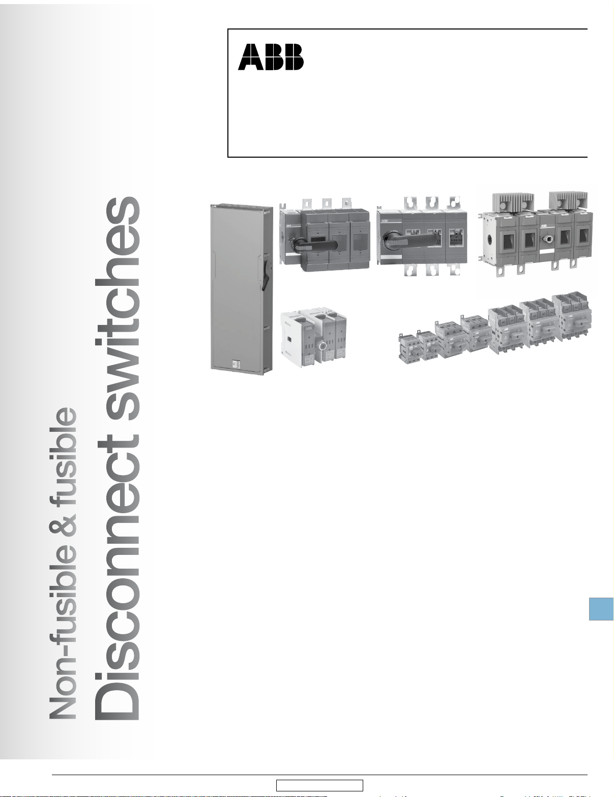
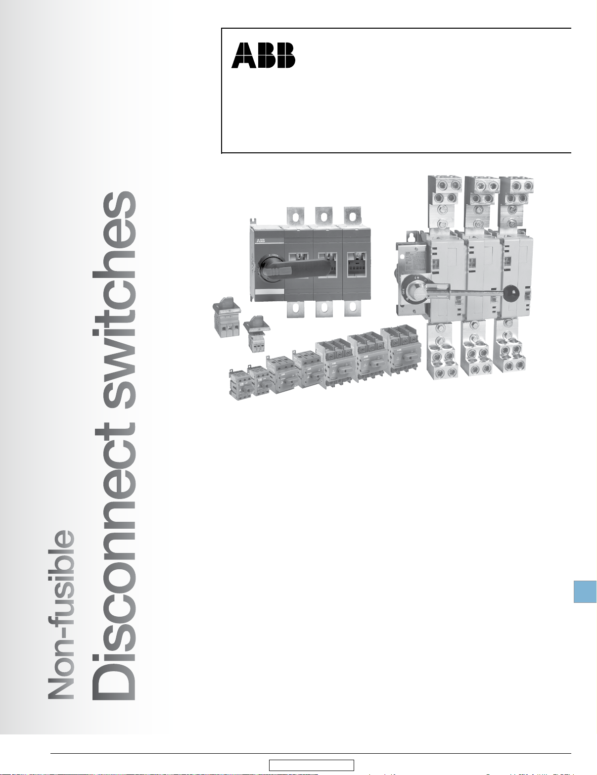
Non-fusible & fusible
disconnect switches, open style
General information
Disconnect
switches
switches
fusio1e
on-tusible &
_.isconnect
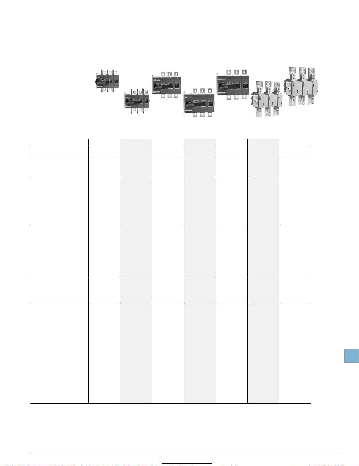
Versatility
ABB disconnect switches are designed to offer maximum versatility in many ways.
Broad range
ABB's open style non-fusible switches have seventeen amperage sizes from 16–2000 A
The fusible range is 30-1200 A. All sizes are compact, heavy duty, 600V, disconnect switches.
Many sizes are available in 2, 3, 4, 6, and 8 pole configurations.
ABB’s offer also includes non-fusible DC switches from 16-600 A specifically designed for
solar applications, heavy duty safety switches (30-1200 A) and general duty enclosed
switches, both fusible fusible (30-800 A) and non-fusible (16-2000 A).
Compact size
The non-fusible disconnect switches' compact dimensions allow panel size reduction in
new applications or easily retrofit into space-sensitive existing installations. The fusible
disconnect occupies only little more panel space than the appropriate fuses.
19
,
Low Voltage Products & Systems 19.1
ABB Inc. • 888-385-1221 • www.abb.us/lowvoltage
Revised January 2015
1SXU000023C0202 Rev. B
Disconnect
switches
General information
International acceptance
UL listed, CSA approved, IEC rated, CE marked, and most other international standards.
UL98 (CSA 22.2 No.4) — UL File # E101914, CSA File #58077
For OT30-OT1200, OS30-1200 and OETL_ switches with pistol grip handles
Suitable for use as motor disconnects or industrial control panel disconnects on service
entrance equipment, panelboards, switchboards, industrial control equipment, motor
control centers, etc. and are horsepower and ampere rated.
UL508 (CSA 22.2 No. 14) — UL File # E63822, CSA File #58077
For OT16 – OT80 switches, OH_ selector handles
Suitable for use in equipment or machinery as motor controllers & motor disconnects and
are horsepower and ampere rated.
IEC
Tested in accordance to IEC 60947-1 and 3.
CE
Compliance with the European Machine Directive IEC/EN 60204.
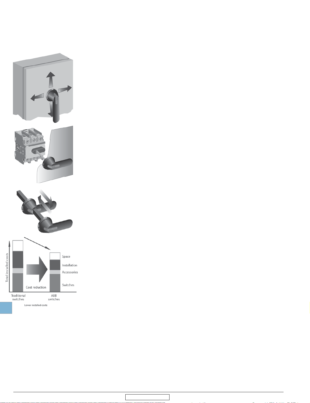
Installation options
Rotary through the door: available in all sizes, non-fusible 16-2000 A;
Flange: versions available in 30-1200 A sizes.
A rotary disconnect may be installed nearly anywhere in a control panel — mounting is not
limited to the upper right hand corner of the panel.
Mount the disconnect where it conveniently fits in your panel and simply install the handle
on the door, in line with the disconnect. The disconnect and handle are mechanically
linked through an easily adjusted shaft. This allows fast and easy installation into panels of
different depths and layouts.
fusible 30-1200 A
19
Traditional
switches
Lower
installed
costs
ABB
switches
Space
Insta
llation
Accessories
Switches
Broad range of accessories
Handles — UL/NEMA type 1, 3R, 12, 4, 4X; IP54, 65, 66
•
Auxiliary contacts available for every disconnect size
•
• Additional power poles
• Additional terminal poles (neutrals & grounds)
• Terminal shrouds
• 6 & 8 pole mechanisms
• Transfer mechanisms
• Bypass mechanisms
• Mechanical interlock mechanisms
• Electro-mechanical interlock mechanisms
19.2 Low Voltage Products & Systems
1SXU000023C0202 Rev. B
Revised January 2015
ABB Inc. • 888-385-1221 • www.abb.us/lowvoltage

Disconnect
switches
General information
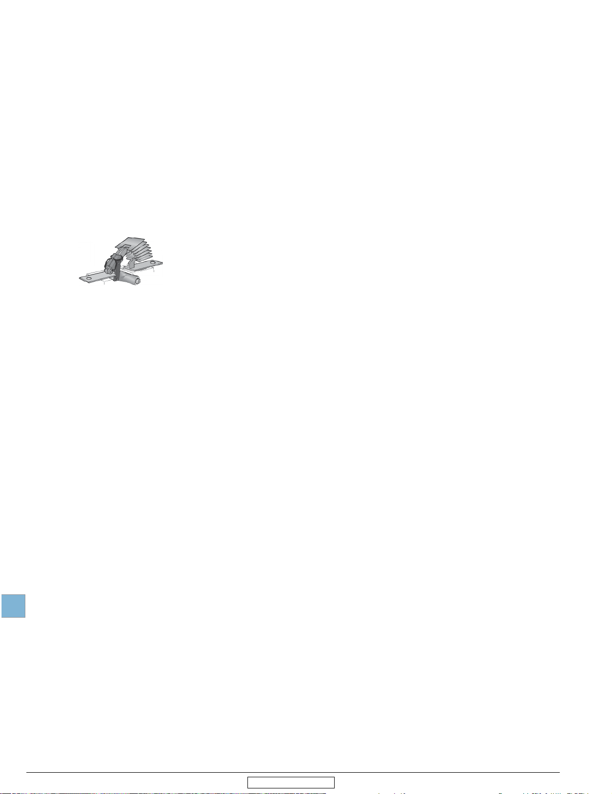
Mounting
Disconnect switches offer several mounting possibilities:
Door mounting on an enclosure door or sidewall for non-fusible, 16 - 100 A
•
• DIN rail mounting for non-fusible, 16 - 200
A; and fusible, 30 - 100 A
• Base mounting with screws for all disconnect sizes
• Adjustable mounting feet for non-fusible, 200 - 1200 A, and fusible 60 -1200 A
Mounting positions
Disconnect switches offer several mounting possibilities:
Terminal connections
Versatile connecting possibilities for non-fusible and fusible switches
• Ring tongue crimp on lugs
• Direct bus
• Terminal lugs
Finger proof
Dead-front construction plus terminal shrouds reduce the risk of touching live
parts, improving safety and reliability of the instalation
Incoming power feed
Disconnect switches can be used equally well with either top or bottom
incoming power feed.
Low Voltage Products & Systems 19.3
ABB Inc. • 888-385-1221 • www.abb.us/lowvoltage
1SXU000023C0202 Rev. B
19
Disconnect
switches
Revised January 2015
General information
Modular construction
Different pole configurations make it easy to install the disconnect inside the enclosures
as well as enhance the external operation through the pistol handles.
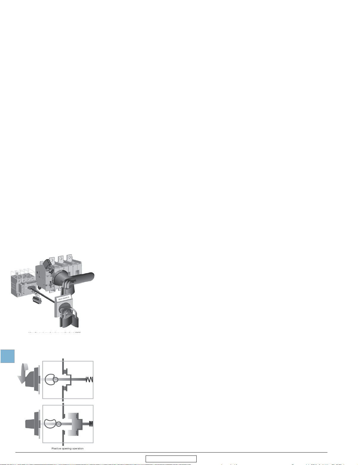
Door interlock
The handle and shaft provide a door interlock; the door cannot be opened when the
switch is in the “ON” position. NOTE: Some handles provide a method for qualified personnel to circumvent the door interlock. This is commonly referred to as a “defeater” mechanism.
19
Padlockable
Handles can be padlocked in the “OFF” position with up to three padlocks. Additionally - with a direct mount handle - the switch mechanism can be directly padlocked in
the “OFF” position when the door is open. NOTE: Some handles can be ordered with
the ability to padlock in both the “ON” & “OFF” positions, please consult your ABB
sales office.
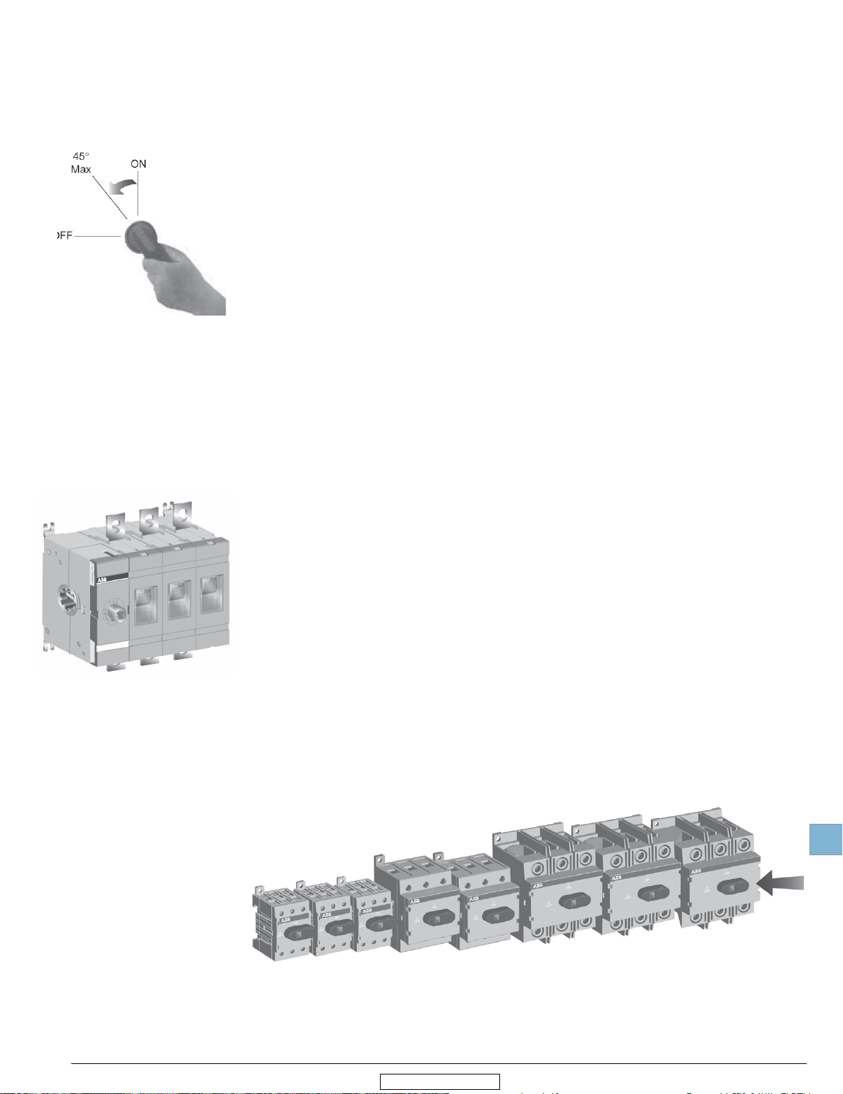
Positive opening operation
All switches operate according to the “positive opening operation” principle. This means the
contacts are opened and closed by a driven mechanism, a solid moving bridge, not merely
springs. This provides reliable position indication to the user; if the disconnect is in the
“OFF” position, the contacts are open.
19.4 Low Voltage Products & Systems
1SXU000023C0202 Rev. B
Pooitive opening ope,-;:ition
ABB Inc. • 888-385-1221 • www.abb.us/lowvoltage
Disconnect
switches
19
Revised January 2015
General information
lFF
45°
Max
Welded contact protection
Positive opening operation safeguards users in case of welded contacts caused by
an overload or short circuit. The handle cannot reach the “OFF” position unless the
contacts are truly open. If any or all of the contacts are welded shut, the disconnect
mechanism will only allow the handle to operate a maximum of 45°. This safeguards
personnel by:
• Alerting them a problem has occurred
• Maintaining the door interlock and
• Not allowing a padlock to be inserted
Clear position indication
All disconnects and handles have clear “ON” and “OFF” designations.
Whether the door is open or closed, it is possible to simply look at the
disconnect and determine if it is “ON” or “OFF”.
Visible blades
Visible blades offer additional safety for non-fusible switches, 200 - 1200 A
Track resistant material
Excellent track resistant material reduces the risk of flash-over between phases
in even the most severe circumstances.
Constant control for non-fusible disconnect switches
The OT16 to OT100 provide the user with constant control over the power circuit.
Whether the enclosure door is open or closed, qualified personnel have the ability to manually operate the disconnect. This is most meaningful when qualified personnel are
working with the enclosure door open: In case of an emergency down-stream, the main
three phase power can be disconnected immediately using the black, direct mounted
handle.
Low Voltage Products & Systems 19.5
ABB Inc. • 888-385-1221 • www.abb.us/lowvoltage
1SXU000023C0202 Rev. B
Disconnect
switches
Revised January 2015
General information
High performance
The
mechanism is quick-make/quick-break, meaning the contacts operate independently
of the speed and force at which the handle is operated. This, in combination with unique,
patented self-cleaning contacts, provides a long, reliable, electrical life.
Superior short circuit protection
Fuses efficiently limit the peak let-through current, i2t, during a fault better than any other
product, contributing to safety and reliability. Selectivity and coordination are easily accom-
plished with fused protection. Fusible disconnect switches accept a wide range of fuses:
Class CC 30A
Class J 30 – 600 A
Class L 800 – 1200 A
Fuse isolation
Fused switches have contacts on both sides of the fuse. The fuses are totally isolated in
the “OFF” position, reducing the risk of electric shock to authorized personnel — even if
the disconnect is being back fed.
19
19.6 Low Voltage Products & Systems
1SXU000023C0202 Rev. B
ABB Inc. • 888-385-1221 • www.abb.us/lowvoltage
Disconnect
switches
Non-fusible
19
Revised January 2015
Jl
,
..
,
II
.•
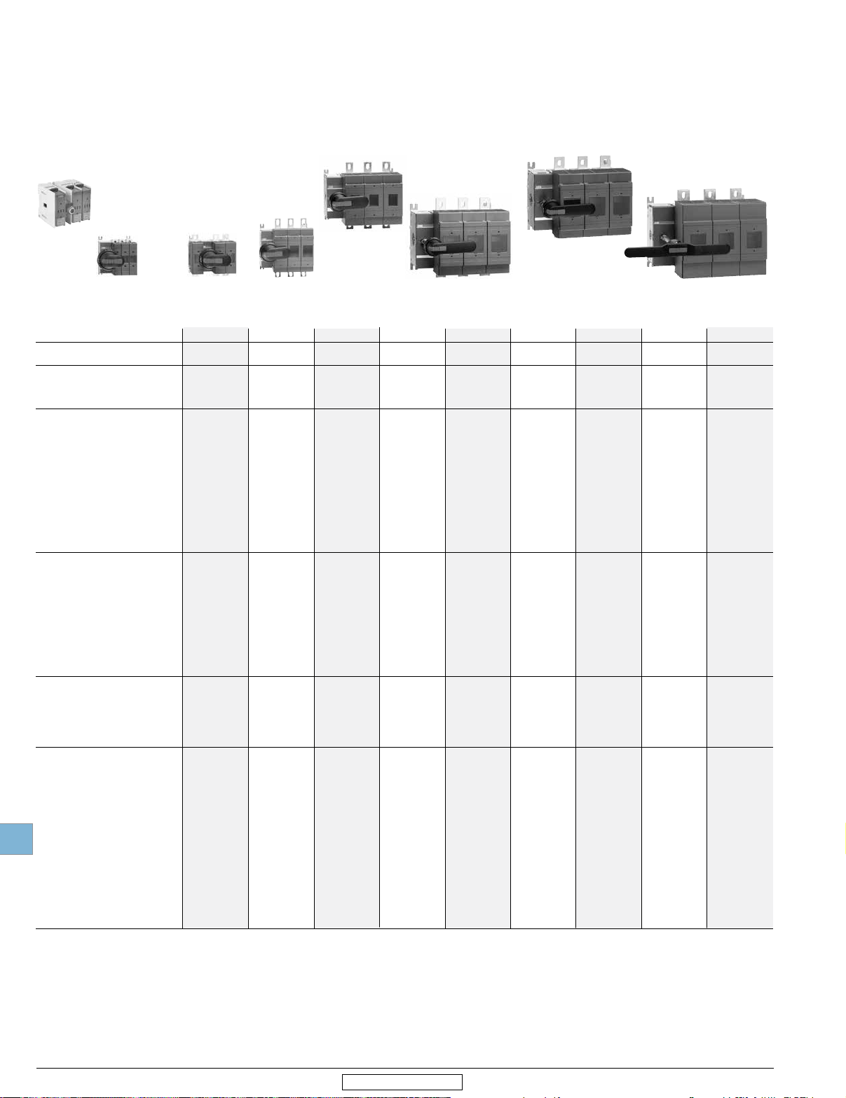
Non-fusible disconnect switches,
open style
16 - 2000 A, 600 VAC
16 - 32 A, 600 VDC
100 - 600 A, 1000 VDC
ABB disconnect switch family includes several different amperage sizes from 16 to 2000
A. The basic construction provides flexibility, safety, and high performance in an extremely
compact size. ABB SwitchLine is a perfect choice for all switching applications from
industrial motor control to construction safety switches.
International acceptance
UL listed, CSA approved, IEC rated, CE marked, and most other international standards.
UL98 (CSA 22.2 No.4) — UL File # E101914, CSA File #58077
For OT30, OT60, OT100, OT200, OT400, OT600, OT800, OT1200
OETL-NF1600, OETL-NF2000 switches, OH_ pistol grip handles
Suitable for use as motor disconnects or industrial control panel disconnects on service
entrance equipment, panelboards, switchboards, industrial control equipment, motor
control centers, etc. and while being horsepower and ampere rated.
UL508 (CSA 22.2 No. 14) — UL File # E63822, CSA File #58077
For OT16 – 80 switches, OH_ selector handles
Suitable for use in equipment or machinery as motor controllers & motor disconnects,
horsepower and ampere rated.
IEC
Tested in accordance to IEC 60947-1 and 60947-3.
Non-fusible
Low Voltage Products & Systems 19.7
ABB Inc. • 888-385-1221 • www.abb.us/lowvoltage
Disconnect switches
CE
Compliance with the European Machine Directive IEC/EN 60204.
For a complete offer including other standards such as IEC, visit:
http://new.abb.com/low-voltage/products/switches
1SXU000023C0202 Rev. B
Disconnect
switches
Non-fusible
19
Revised January 2015
General information
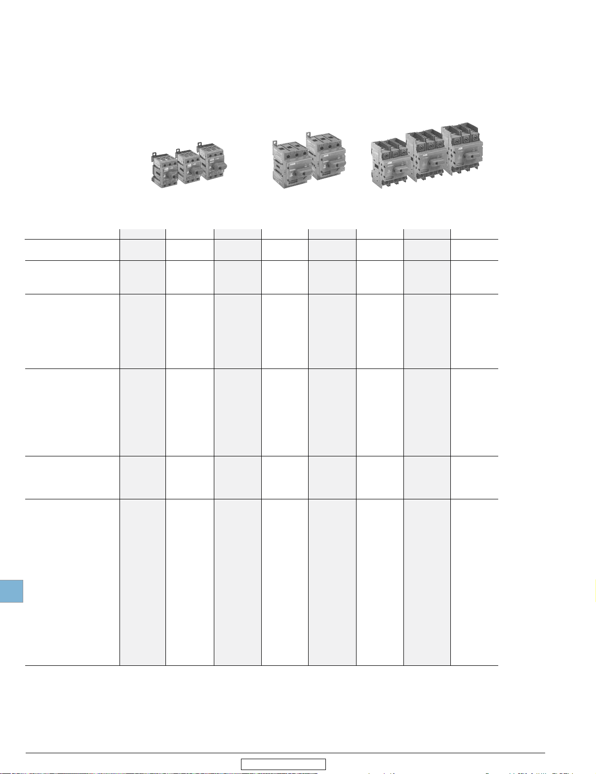
Selection guide
OT16 – 100
OT16F3 OT25F3 OT40F3 OT63F3 OT80F3 OT30F3 OT60F3 OT100F3
Catalog number 3 pole OT16F3 OT25F3 OT40F3 OT63F3 OT80F3 OT30F3 OT60F3 OT100F3
General purpose A 20 30 40 60 80 30 60 100
amp rating
Approvals 1
Technical ratings – UL,CSA 2
Max operating voltage V 600 600 600 600 600 600 600 600
Max horsepower rating
Three phase
240V HP 5 7.5 10 15 20 10 20 30
480V HP 10 15 20 30 40 20 40 50
600V HP 10 20 25 30 40 30 40 50
Single phase
120V HP 1 1.5 2 2 2 2 3 5
240V HP 2 3 5
Technical ratings – IEC
Rated insulation and operational
voltage. AC20 and DC20 V 750 750 750 750 750 750 750 750
Rated thermal current, I
AC 20/DC 20 open A 25 32 40 63 80 40 63 115
AC 20/DC 20 enclosed A 25 32 40 63 80 40 63 115
AC 21A ≤500V A 16 25
Rated operational power AC23
Physical characteristics
Weight 3 3 pole lb 0.24 0.24 0.24 0.59 0.59 0.79 0.79 0.79
Dimension 3 pole H in 2.68 2.68 2.68 3.60 3.60 3.94 3.94 3.94
Accessories
Terminal lug kit Integral Integral Integral Integral Integral Integral Integral Integral
Terminal shroud
Auxiliary contact
Shaft/handle diameter 6mm 6mm 6mm 6mm 6mm 6mm 6mm 6mm
Handle UL/NEMA type
Type 1, 3R, 12
Type 1, 3R, 4, 4X, 12
Handle type
Selector
Pistol
Recommended pistol handle length 45 - 65
Maximum recommended shaft length 290
Conversion kits
6 pole
Transfer
Bypass
Mechanical interlock
Electrical interlock — — — — — — — —
• = Available
— = Not available
2 pole N/A N/A N/A N/A N/A N/A N/A N/A
3 pole
UL508 & IEC UL508 & IEC UL508 & IEC UL508 & IEC UL508 & IEC UL98 & IEC UL98 & IEC UL98 & IEC
4 pole UL508 & IEC UL508 & IEC UL508 & IEC UL508 & IEC UL508 & IEC UL98 & IEC UL98 & IEC UL98 & IEC
2
th
≤690V A 16 25 40 63 80 40 63 100
400/415V kW 7.5 9 11 22 37 15 18.5 37
690V kW 7.5 9 11 15 18.5 15 15 37
W in 1.38 1.38 1.38 2.07 2.07 2.76 2.76 2.76
D in 2.20 2.20 2.20 2.85 2.85 2.95 2.95 2.95
40
7.5 10
63 80 40 63 100
5 7.5 15
• • • • • • • •
• • • • • • • •
.24" x .24" .24" x .24" .24" x .24" .24" x .24" .24" x .24" .24" x .24" .24" x .24" .24" x .24"
• • • • • • • •
• • • • • • • •
• • • • • — — —
• • • • • • • •
mm
45 - 65
mm
45 - 65
mm
• • • • • • • •
• • • • • • • •
• • • • • • • •
• • • • • • •
290
mm
290
mm
mm
45 - 65
290
mm
mm
45 - 65
290
mm
mm
45 - 65
290
mm
mm
45 - 65
290
mm
mm
45 - 65
290
mm
mm
•
1 UL listed switches are also listed for CSA Standards.
2 For complete technical information please see pages 19.50-19.14.
3 Disconnect only.
19.8 Low Voltage Products & Systems
1SXU000023C0202 Rev. B
ABB Inc. • 888-385-1221 • www.abb.us/lowvoltage
Disconnect
switches
Non-fusible
19
Revised January 2015
General information
Selection guide
OT200 - 1200
OETL-NF1600 - 2000
OT200U03 OT400U03 OT600U03 OT800U03 OT1200U03 OETL-NF1600SW OETL-NF2000SW
Catalog number 3 pole OT200U03 OT400U03 OT600U03 OT800U03 OT1200U03 OETL-NF1600SW OETL-NF2000SW
General purpose A 200 400 600 800 1200 1600 2000
amp rating
1
Approvals
Technical ratings – UL,CSA 2
Max operating voltage V 600 600 600 600 600 600 480
Max horsepower rating
Three phase
240V HP 75 125 200
480V HP 150 250 450 500 — — —
600V HP 200 350 500
Single phase
120V HP — — — — — — —
240V HP — — — — — — —
Technical ratings – IEC 2
Rated insulation and operational
voltage. AC20 and DC20 V 1000 1000 1000 1000 1000 1000 1000
Rated thermal current, I
AC 20/DC 20 open A 250 400 800 1250 1600 2500 2500
AC 20/DC 20 enclosed A 250 400 800 1250 1600 2300 2300
AC 21A ≤500V A 250 400 800 1250 1600 2500 4 25004
Rated operational power AC23
Physical characteristics
Weight 3 3 pole lb 2.9 5.7 11.4 35.9 38.55 127.7 127.7
Dimension 3 pole H in 6.69 8.66 10 19.09 19.09 25.04 25.04
Accessories
Terminal lug kit
Terminal shroud
Auxiliary contact
Shaft/handle diameter 6mm 12mm 12mm 12mm 12mm 12mm 12mm
Handle UL/NEMA type
Handle type
Recommended pistol handle length 65 - 80
Maximum recommended shaft length 290
Conversion kits
Electrical interlock
S = Standard feature
• = Available
— = Not available
≤690V A 250 400 800 1250 1600 25004 25004
400/415V kW
690V kW
Type 1, 3R, 12
Type 1, 3R, 4, 4X, 12
Selector — — — — — — —
Pistol
6 pole
Transfer
Bypass
Mechanical interlock
2 pole UL98 & IEC UL98 & IEC UL98 & IEC UL98 & IEC UL98 & IEC UL98 & IEC UL98 & IEC
3 pole UL98 & IEC UL98 & IEC UL98 & IEC UL98 & IEC UL98 & IEC UL98 & IEC UL98 & IEC
4 pole UL98 & IEC UL98 & IEC UL98 & IEC
th
140
250
W in 6.67 8.7 10.64 14.29 14.29 18.43 18.43
D in 3.30 3.35 5.56 4.92 4.92 10.67 10.67
OZXA-200
220
400
OZXA-400
450
800
OZXA-800
UL98 & IEC
200
500
710 710
1200 1200
OZXA-1200
UL98 & IEC
— — —
— — —
OZXA-1200
UL98 & IEC
400 400
— —
OZXA-28
UL98 & IEC
OZXA-28/2
• • • • • — —
• • • • • • •
.24" x .24" .47" x .47" .47" x .47" .47" x .47" .47" x .47" .47" x .47" .47" x .47"
• • • • • • •
• • • • • • •
• • • • • • •
mm
mm
• • • • •
• • • • •
• • • • •
• • • • • • •
• • • • • •
125 - 175
595
mm
mm
125 - 175
595
mm
mm
125 - 175
595
mm
mm
125 - 175
595
mm
mm
125 - 175
mm
595
mm
— —
— —
— —
125 - 175
595
mm
mm
•
1 UL listed switches are also listed for CSA standards.
2 For complete technical information please see pages 19.50-19.74.
3 Disconnect only.
4 IEC 947-3 Utilization Category B, Infrequent operation.
Low Voltage Products & Systems 19.9
ABB Inc. • 888-385-1221 • www.abb.us/lowvoltage
1SXU000023C0202 Rev. B
Disconnect
switches
Non-fusible
19
Revised January 2015
Selection information
Standard part number designation 1
Non-Fusible OT Switches (16 to 100A)
OT 16 F 3 C
Amperage
16 = 20 amps* 63 = 60 amps* 60 = 60 amps
25 = 30 amps* 80 = 80 amps* 100 = 100 amps
40 = 40 amps* 30 = 30 amps
Number of Poles
3 = 3 poles 4 = 4 poles 6 = 6 poles
Special Configuration
Blank = Non-fusible disconnect switch
C = Double throw switch
cULus 508 listed switches. OT30_, OT60_ and OT100_ are cULus 98 listed
*
Non-Fusible OT Switches (200A and above)
OT 200 U 03 C
Amperage
200 = 200 amps 400 = 400 amps 600 = 600 amps 800 = 800 amps 1200 = 1200 amps
Number of Poles & Placement of Mechanism
02 = 2 poles to right of mechanism
03 = 3 poles to right of mechanism
30 = 3 poles to left of mechanism
12 = 1 pole to left, 2 poles to right of mechanism
Special Configuration
Blank = Non-fusible disconnect switch
C = Double throw switch
All OT200U_, OT400U_, OT600U_ , _OT800U_ and OT1200U_ switches are cULus 98 listed.
Selector Handles
04 = 4 poles to right of mechanism
OHB S 1 P H
Pistol Handles
O H B 65 J 6 E011
Handle Color
B = black Y = Red/Yellow
Physical Size
Connection to disconnect
A = external shaft P = snap on R = screw
Protection Class
H = Nema 1
Handle Color
B = Black Y = Red/Yellow M = Stainless Steel
Handle Length
65 = 65mm 80 = 80mm 125 = 125mm 145 = 145mm 274 = 274mm 330 = 330mm
Environmental Rating
J = 1, 3R, 12 L = 1, 3R, 12, 4, 4X
Shaft Diameter
6 = 6mm 12 = 12mm
Special Configuration
Blank = for disconnect switches, fusible and non-fusible
E011 = 3 position double throw handle
EH = Stainless steel hasp
J= Nema 1, 3R, 12
1 Part designation keys are provided for reference only. Not all variations or configurations are available.
19.10 Low Voltage Products & Systems
1SXU000023C0202 Rev. B
ABB Inc. • 888-385-1221 • www.abb.us/lowvoltage
Disconnect
switches
Non-fusible
19
Revised January 2015
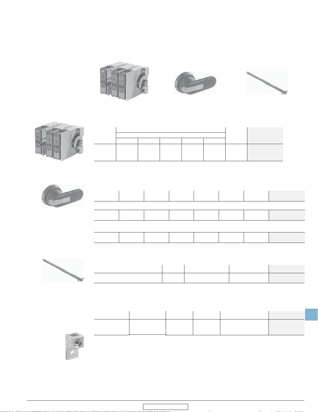
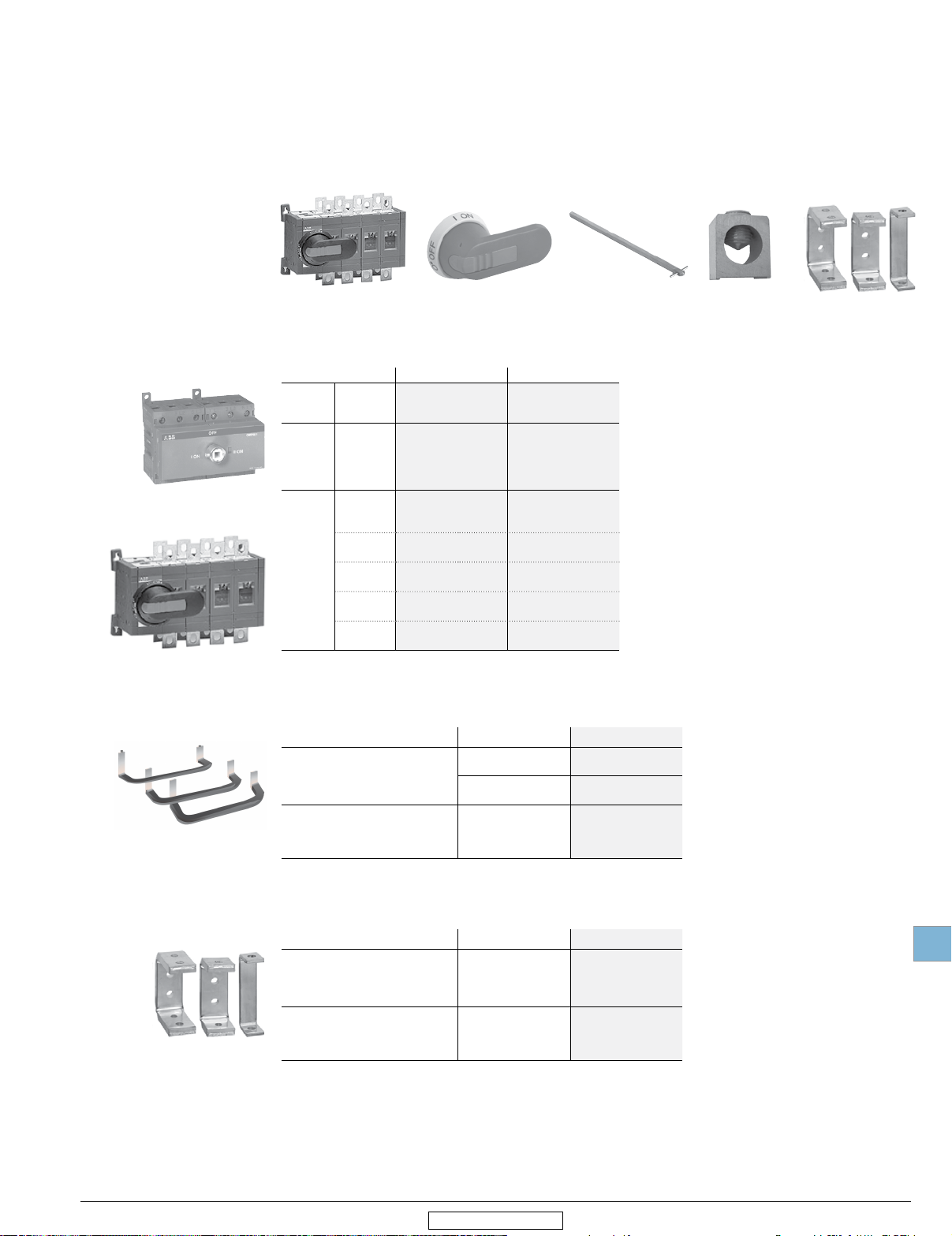
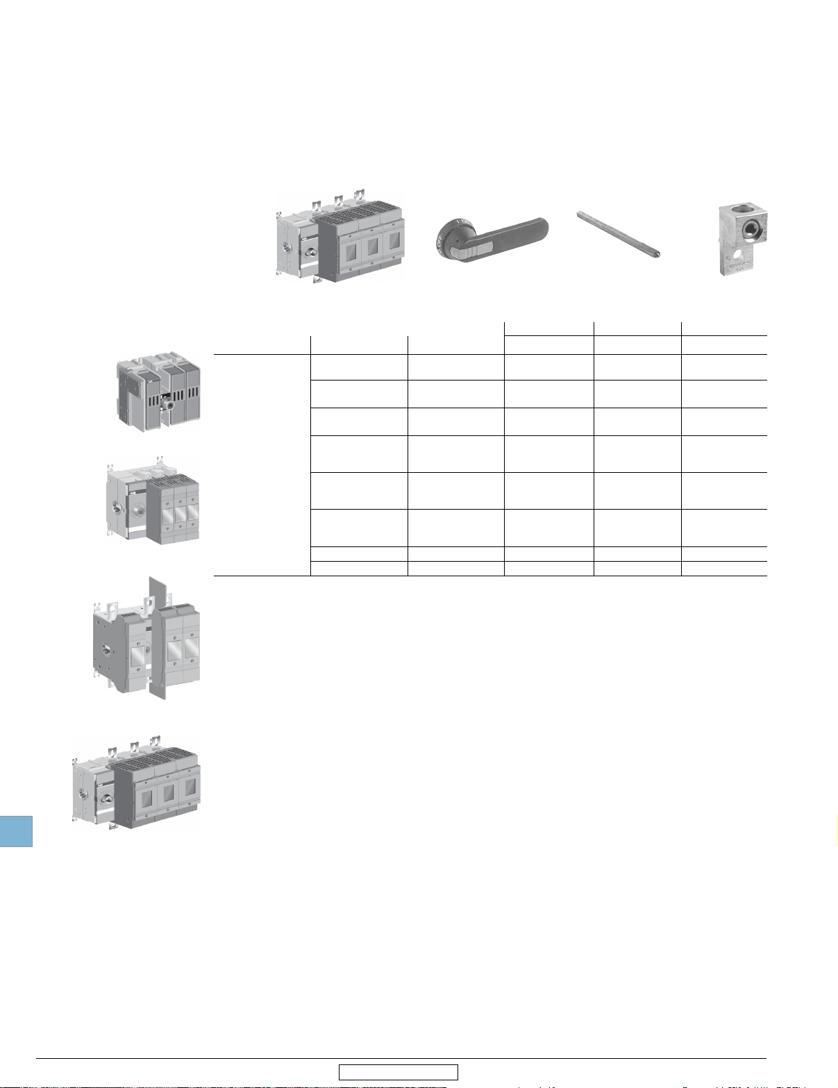
Base & DIN rail mounted 1
16 - 2000 A
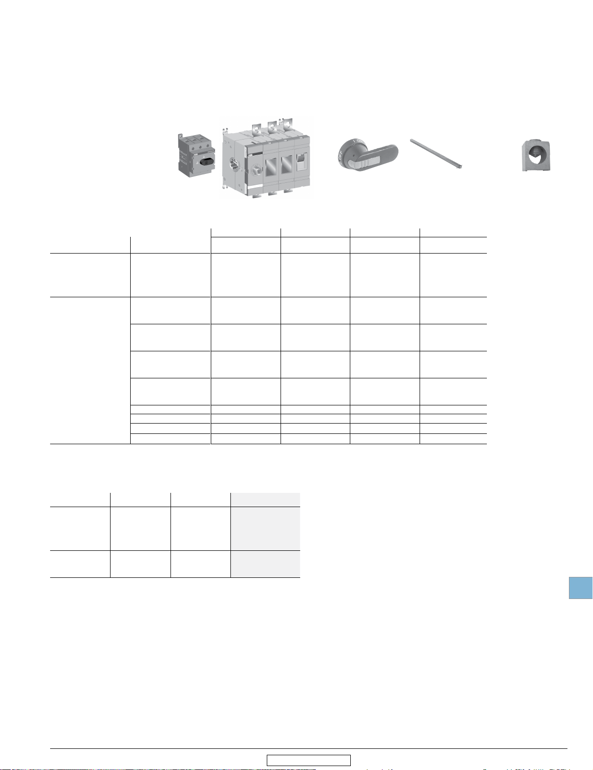
For a complete assembly,
please select one of each:
1 disconnect (page 19.11)
1 handle (page 19.30)
1 shaft (page 19.32)
1 terminal lug kit (page 19.34)
NOTE: For additional accessories, see
pages 19.29 - 19.40.
(Lug kits only necessary on switches 200A and above)
UL Standard
UL 508
UL 98
UL general purpose
amp rating
20
30
40
60
80
30
60
100
200
400
600
+
Lug kit
OZXA_
4 Pole
2
2
+
Shaft
OXS_
2
OXP_
6 Pole
OT16F6
OT25F6
OT40F6
OT63F6
OT80F6
OT30F6
OT60F6
OT100F6
—
—
—
—
—
—
—
3
+
Disconnect
OT_F_
OT_U_
2 Pole 3 Pole
Catalog number Catalog number Catalog number Catalog number
—
—
—
—
—
—
—
—
OT200U02
OT400U02
OT600U02
OT16F3
OT25F3
OT40F3
OT63F3
OT80F3
OT30F3
OT60F3
OT100F3
OT200U03
OT200U30
OT200U12
OT400U03
OT400U30
OT400U12
OT600U03 OT600U04
Handle
OH_S_
OH_B_
OT200U04
OT400U04
800
1200
1600
2000
OT800U02 OT800U03 OT800U04 —
OT1200U02 OT1200U03 OT1200U04 —
OETL-NF16002SW OETL-NF1600SW OETL-NF16004SW —
OETL-NF20002SW OETL-NF2000SW OETL-NF20004SW —
Bulk packed 3 Pole, 600 VAC Switches - order quantity is 1 for bulk package
UL Standard
UL508
UL98
UL general purpose
amp rating
20
30
40
60
80
30
60
100
Bulk pack Quantity Catalog number
50
50
50
50
50
25
25
25
OT16F3/B50
OT25F3/B50
OT40F3/B50
OT63F3/B50
OT80F3/B50
OT30F3/B25
OT60F3/B25
OT100F3/B25
Above 200A, base mount with screws only.
A snap on fourth pole may be added on 16-100A switches. See page 19.36.
For a 6 or 8 pole switch 200 A and above, a conversion mechanism accessory kit can be used with two 3 or 4 pole switches. See page 19.39.
Vertical busbar provided as standard on OETL-NF1600-OETL-2000 switches. For alternate back or edgewise mounting busbar, see page 19.38.
DIN rail mounting required adaptador OSGZD1
Low Voltage Products & Systems 19.11
ABB Inc. • 888-385-1221 • www.abb.us/lowvoltage
1SXU000023C0202 Rev. B
Disconnect
switches
Non-fusible
19
Revised January 2015
Door mounted 1
16 - 100 A
For a complete assembly,
please select one of each:
1 disconnect (page 19.12)
1 handle (page 19.31)
NOTE: For additional accessories, see
pages 19.29 - 19.40.
OT_FT
2
=
4 Pole
Catalog
number
See page 19.36 for
fourth poles
Snap-on mounted
Disconnect
UL Standard
UL508
UL98
OT_FT_
+
UL general purpose
amp rating
20
30
40
60
80
30
60
100
Handle
OH_S_
3 Pole
Catalog
number
OT16FT3
OT25FT3
OT40FT3
OT63FT3
OT80FT3
OT30FT3
OT60FT3
OT100FT3
Bulk packed 3 Pole, 600 VAC Switches - order quantity is 1 for bulk package
UL Standard
UL508
UL98
UL general purpose
amp rating
20
30
40
60
80
30
60
100
Bulk pack Quantity Catalog number
50
50
50
50
50
25
25
25
OT16FT3/B50
OT25FT3/B50
OT40FT3/B50
OT63FT3/B50
OT80FT3/B50
OT30FT3/B25
OT60FT3/B25
OT100FT3/B25
handle
Screw mounted
handle
1 Door mounted switches do not provide door interlock
2 Door mounted switches do not require shafts
19.12 Low Voltage Products & Systems
1SXU000023C0202 Rev. B
ABB Inc. • 888-385-1221 • www.abb.us/lowvoltage
Disconnect
switches
Non-fusible
19
Revised January 2015
For a complete assembly,
please select one of each:
1 disconnect
1 handle
1 shaft
1 terminal lug kit
Special configuration
Side operated
30 - 100 A
+
+
OSNF30-S
OH_J_
OXP6X_
Disconnect
OSNF_-S
Handle
OH_J_E00S
Side operated disconnects — 3 pole
UL
general
purpose
amp rating
200V 208V 240V 480V 600V
30 5 7.5 7.5 15 20 1.90
60 15 15 15 30 50 3.90
100 25 25 30 60 75 4.50
Maximum horsepower rating
Three phase
Handles
UL/NEMA type Color
For use with OSNF30-S
1, 12, 3R
Black
Red/Yel OHY65J6E00S
For use with OSNF60-S — OSNF100-S
1, 12, 3R
Black
Red/Yel OHY80J6E00S
Length
inches/mm
Marking Defeatable Padlockable
2.65/65 O/I & Off/On Ye s Ye s
3.1/80 O/I & Off/On Yes Ye s
Shafts
For use with:
OSNF30-S
OSNF60-S – OSNF100-S
Length
(Inches/mm)
6.7/170 0.08 OXP6X170
8.3/210 0.10 OXP6X210
Description
.24 x .24” (6 x 6mm)
.24 x .24” (6 x 6mm)
Weight
(Lbs.)
Catalog
number
OSNF30-S
OSNF60-S
OSNF100-S
Weight
(Lbs.)
0.29
0.30
Weight
(Lbs.)
Shaft
OXP_X_
OHB65J6E00S
OHB80J6E00S
Catalog
number
Catalog
number
Terminal lug kits
For use with:
OSNF30-S — Cu — Integral
OSNF60-S — Cu — Integral
OSNF100-S 0.43 Cu/Al 6 OZXA-24
OZXA-24
Low Voltage Products & Systems 19.13
ABB Inc. • 888-385-1221 • www.abb.us/lowvoltage
For 100 A disconnect only
Fusible switches with solid links installed
Wire
size
#18 – 8
#14 – 4
#14 – 2/0
Weight
Wire
type
Lugs
per kit
Catalog
number
1SXU000023C0202 Rev. B
Disconnect
switches
Non-fusible
19
Revised January 2015
Special configurations
Shaft operated flange
30 - 100 A
+ +
Disconnect Assembly
OT_F3-F
OT_F_-F
DSFHN-HS_
Handle
DSFHN_
Flange operated (Shaft) - 3 poles
UL general
purpose amp rating
30
60
100
OT30F3-F
OT60F3-F
OT100F3-F
Flange handles — for use with OT30, OT60, OT100
UL/ NEMA type Marking
1, 3R, 12
4, 4X
OFF/ON
OFF/ON
Shafts
For use with:
OT30 - OT100F3
Maximum enclosure
depth (inches)
16
24
Catalog
number
Defeatable Padlockable
No
No
Catalog
number
OTFS-16
OTFS-24
Shaft
OTFS_
Yes
Yes
Catalog
number
DSFHN-HS12
DSFHN-HS4
OTFS_
19.14 Low Voltage Products & Systems
1SXU000023C0202 Rev. B
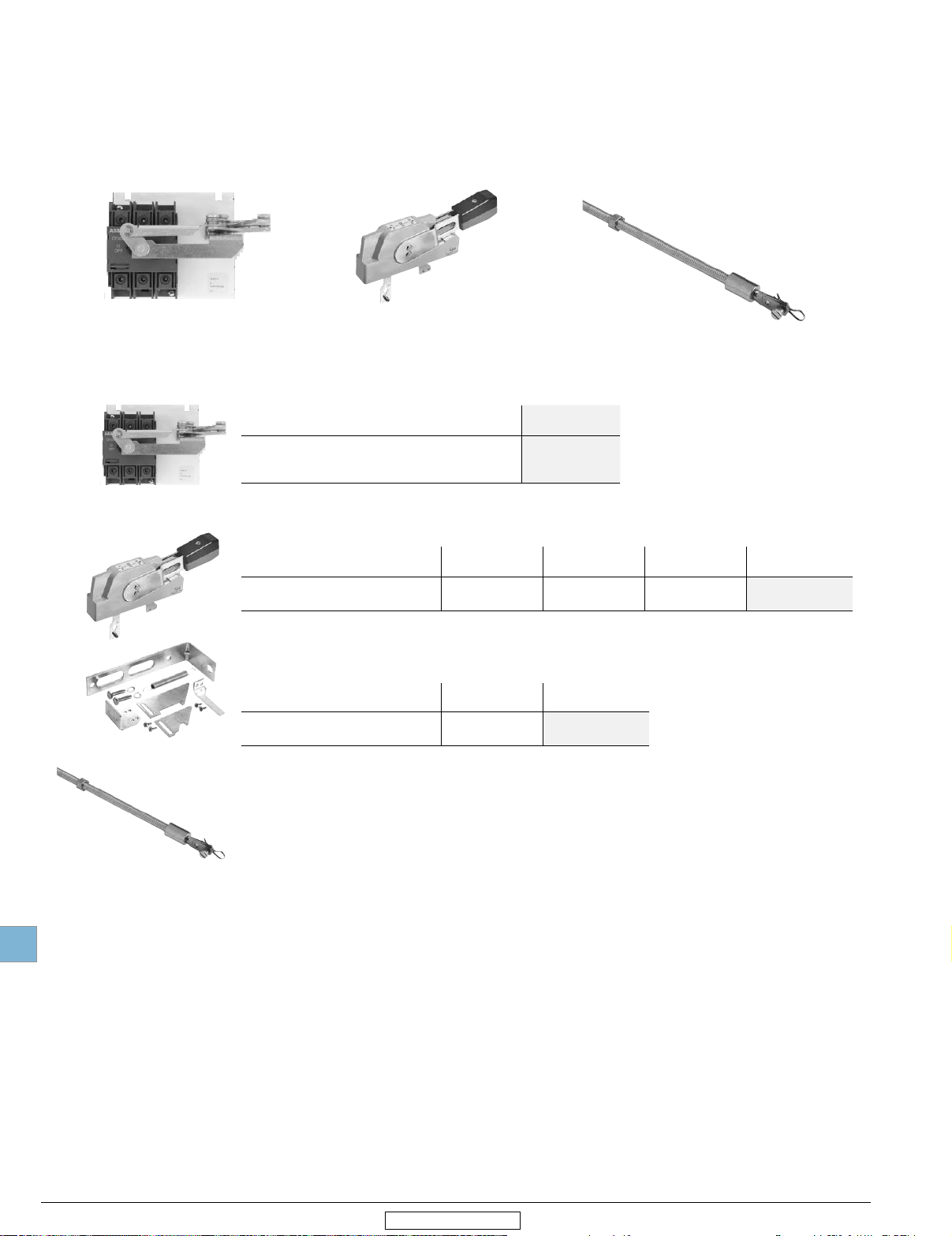
Flange operated fusible and non-fusible disconnect switches
ABB’s solutions comply with NFPA79 requirements for Flange Operated Fusible and Non-fusible Disconnect Switches.
NFPA 79 requires main disconnecting means to be operable without the use of accessory tools or devices, independent of door
position. This code also includes an interlocking provision to prevent the closing of disconnects while the enclosure door is open,
unless an interlock is operated by a deliberate action.
The flange operated disconnect switches are available as ridged shaft or flexible cable operated versions. The cable operated
version allows you to install the disconnect switch virtually anywhere in the enclosure depending on the length of the cable.
Cables are available in lengths up to 84 inches.
The designs are cost-effective NFPA 79 solutions offering quick and easy installation.
ABB Inc. • 888-385-1221 • www.abb.us/lowvoltage
Disconnect
switches
Non-fusible
19
Revised January 2015
Special configurations
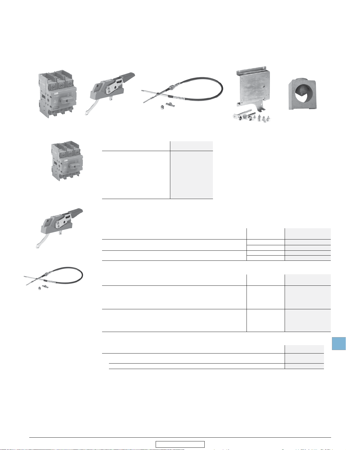
Cable operated flange
30 - 1200 A
+ + + +
Switch Handle Cable
Flange Operated (cable) - 3 poles
UL general purpose
amp rating
OT30F3
OT60F3
OT100F3
OT200U30
OT200U03
OT400U30-FC
OT600U30-FC
OETL-NF800A-FC
OETL-NF1200-FC
OT_F3
30
60
100
200
200
400
600
800
1200
Flange handles — UL98; UL file #E10191
For use with: Environmental
OHF1C12
OT400U30-FC, OT600U30-FC, OETL-NF800-FC, OETL-NF1200-FC
OT30 - 100F3, OT200U30/03
Flexible cables
For use with:
OXC1L_
OT400U30-FC, OT600U30-FC, OETL-NF800-FC, OETL-NF1200-FC
OT30 - 100F3, OT200U30/03
Catalog
number
Operating mechanism
NEMA 1, 3R, 12 OHF1C12
NEMA 4, 4X OHF1C4
NEMA 1, 3R, 12 K7FCH
NEMA 4, 4X K7FCH4
Cable length (inches)
2
rating
36
48
60
72
84
48
60
72
84
Lug kit 1
OXC1L36
OXC1L48
OXC1L60
OXC1L72
OXC1L84
K7C048
K7C060
K7C072
K7C084
Catalog
number
Catalog
number
Operating mechanisms
OT400U30-FC, OT600U30-FC, OETL-NF800-FC, OETL-NF1200-FC
For disconnects above 100 A
Rotate the OT_03 disconnect 180 degrees to mount on the operating mechanism
Operating mechanism required for OT30-200. Not required for OT400-1200 (included)
Low Voltage Products & Systems
ABB Inc. • 888-385-1221 • www.abb.us/lowvoltage
For use with:
OT30 - 100F3 MKCS1
OT200U30, OT200U03
Catalog
number
MKCS4
Included
1SXU000023C0202 Rev. B
19.15
Disconnect
switches
Non-fusible
19
Revised January 2015
Special configurations
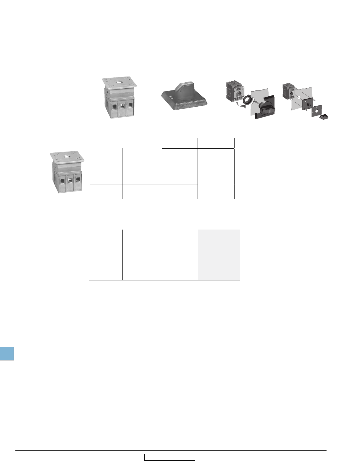
Accessories for flange operated disconnects
30 - 1200 A
OTS_L_
OTS_S_
Terminal lug kits
For use
OT200U30
OT400U30-FC
OT600U30-FC
OETL-NF800-FC
OETL-NF1200-FC
with
Wire
size
#4 – 300 kcmil Cu/Al 6 OZXA-200
#2 - 600 kcmil Cu/Al - 6
(2) #2 - 600 kcmil
(2) #2 - 600 kcmil
(4) #2-600 kcmil Cu/Al - 6 OZXA-28
Wire
type
Cu/Al - 6
Cu/Al -
Description Lugs per kit
-
OZXA-400
OZXA-800
6
OZXA-30
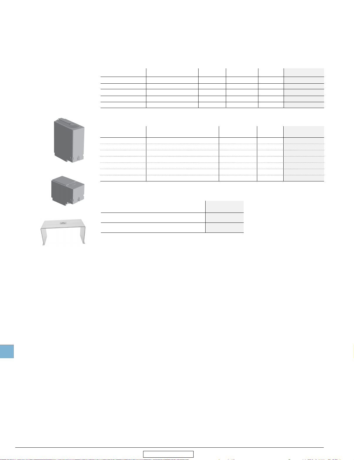
Terminal shrouds
For use with Description, qty per kit
OT30 - OT100
OT200
OT200
OT400U30-FC 3 pole shroud, 1 pc 0.13 OTS403
OT600U30-FC
OETL-NF800
OETL-NF1200
3 Pole shroud, 1 pc
Single Pole Long Type Shroud, 3 pcs
Single Pole Short Type Shroud, 3 pcs
3 pole shroud, 1 pc
3 Pole shroud, 2 pcs
3 Pole shroud, 2 pcs
For full protection
order
2 kits
2 kits
2 kits
2 kits
2 kits
1 kit
1 kit
Weight
(lbs.)
0.02 OTS125T3
0.2 OTS250G1L/3
0.13
0.11 OTS603
0.88 OETL-2X800A
1.2 OETL-2X119
OTS250G1S/3
Door hardware NEMA 12
Item
Safety door latch, 2 points, door less than 40" high
Safety door latch, 3 points, door greater than 40" high
Catalog
number
KDH2R
KDH3R
Catalog
number
Catalog
number
OTS_03
19.16 Low Voltage Products & Systems
1SXU000023C0202 Rev. B
ABB Inc. • 888-385-1221 • www.abb.us/lowvoltage
Disconnect
switches
Non-fusible
19
Revised January 2015
For a complete assembly,
please select one of each:
disconnects (page 19.17)
1
1 handle (page 19.30)
1 shaft (page 19.32)
1 terminal lug kit (page 19.34)
1 bridging bar (page 19.17)
NOTE: For additional accessories, see
pages 19.29 - 19.40
Special configuration
Double throw disconnects
16 - 800 A
+ +
Disconnect
Handle
Shaft
+
Lug kit
+
Bridging bars
OT_F3C
OT_U_C
OZXA_
3 Pole
UL general
UL
only
UL508
UL98
purpose amp
rating
20
30
40
60
80
30
60
100
200
400
600 OT600U03C OT600U04C
800 OT800U03C OT800U04C
Catalog number Catalog number
OT16F3C
OT25F3C
OT40F3C
OT63F3C
OT80F3C
OT30F3C
OT60F3C
OT100F3C
OT200U03C
OT200U30C
OT400U03C
OT400U30C
Parallel connection kits / jumpers
Required for OT16_C through OT100_C
Description For use with:
OT16...40F3C
3 Pole Kit
4 Pole kit
OT63...80F3C
OT30F3C, OT60F3C,
OT100F3C
OT16...40F3C + 4th pole
OT63...80F3C + 4th pole
OT30...100F3C + 4th pole
4 Pole
—
—
—
—
—
—
—
—
OT200U04C
OT400U04C
Catalog number
OZXA33
OZXA38
OZXA40
OZXA32
OZXA39
OZXA41
Bridging busbar kits
Required for OT200_C through OT800_C
Description For use with:
OT200_C
3 Pole Kit
4 Pole kit
_
OTZC
Bridging bars are required on 200-600A double throw switches to operate as standard
double throw switches. Otherwise, they will operate as two mechanically interlocked switches.
For disconnects above 100 A
A snap on power pole may be added to build a 4 pole 16-100A double throw switch. See page 19.36
Low Voltage Products & Systems 19.17
ABB Inc. • 888-385-1221 • www.abb.us/lowvoltage
OT400_C
OT600_C
OT800_C
OT200_C
OT400_C
OT600_C
OT800_C
Catalog number
OTZC13
OTZC23
OTZC33
OTZC53
OTZC14
OTZC24
OTZC34
OTZC54
1SXU000023C0202 Rev. B
Disconnect
switches
Non-fusible
19
Revised January 2015
OTDC16US2
OTDC16US4
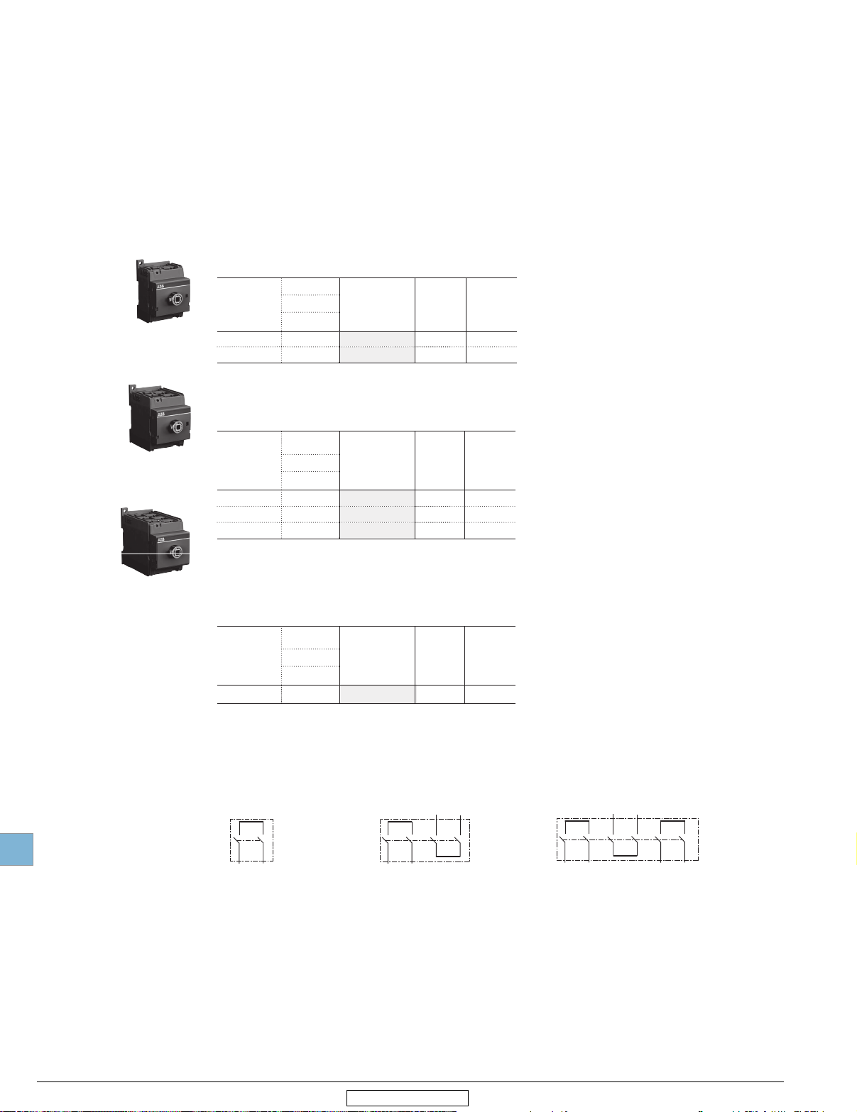
OTDC Solar disconnect switches
16 - 32 A, 600 VDC
OTDC_, base or DIN-rail mounting, UL508i
Touch-safe IP20 protected terminal clamps included. Types OTDC16…32US include premounted short circuit link OEZXY86. Shafts and handles to be ordered separately.
Single circuit (2 poles in series)
Number
f
o
poles
2 16 OTDC16US2
2 25 OTDC25US2
Double circuit (2 x 2 poles in series)
Number
of
poles 600 VDC
4 16 OTDC16US4
4 25 OTDC25US4
4 32 OTDC32US4
Rating [A]
UL508i
600 VDC
Rating [A]
UL508i
Catalogue
Number
Catalogue
Number
Handle
& Shaft
diam.
6 mm
6 mm
Handle
& Shaft
diam.
6 mm
6 mm
6 mm
Weight
(lbs)
0.33
0.33
Weight
(lbs)
0.33
0.33
0.33
OTDC16US6
Triple circuit (3 x 2 poles in series)
Number
of
poles
6 16 OTDC16US6
Rating [A]
UL508i
......................
600 VDC
Catalogue
Number
I I I
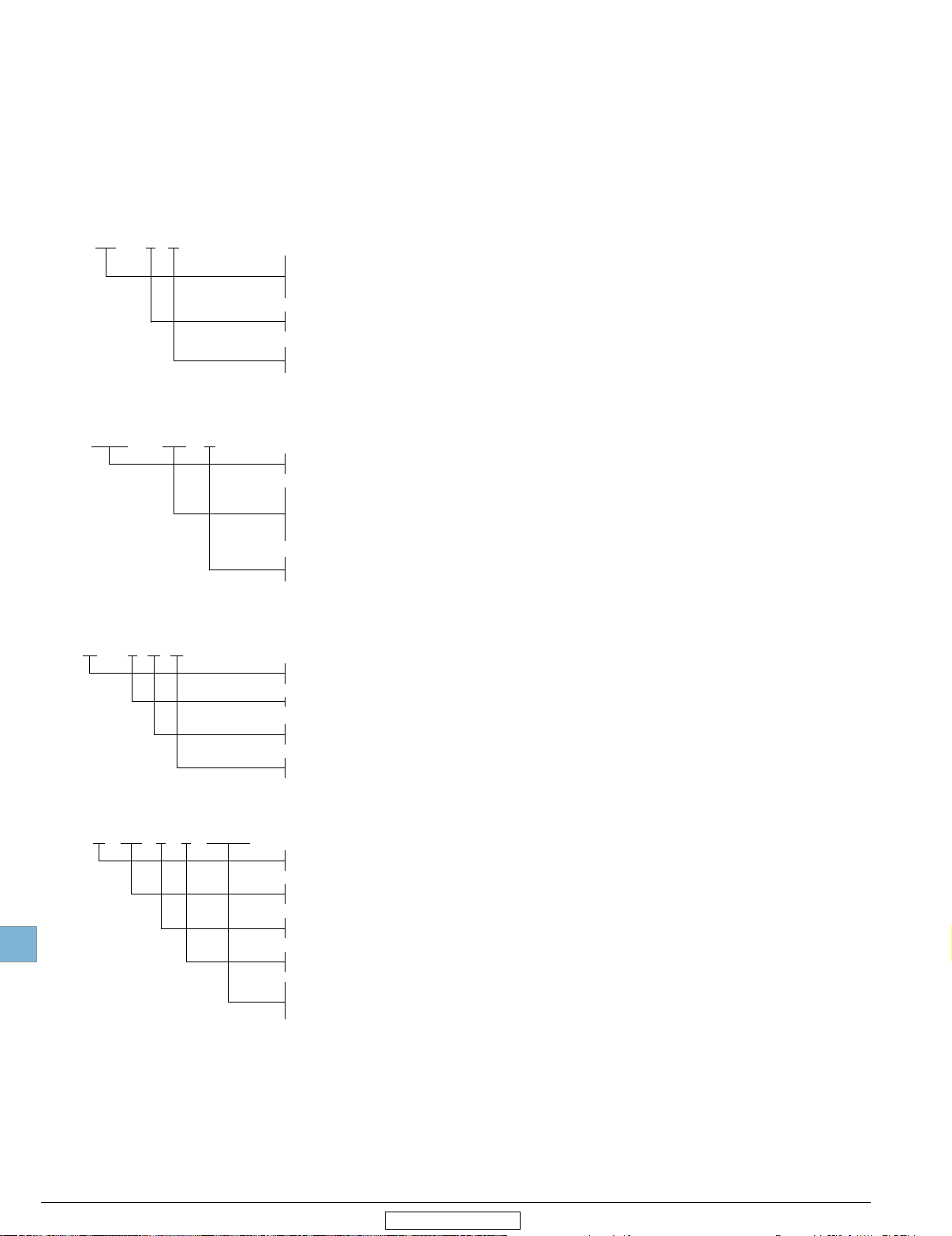
Wiring diagrams
i------------1----1-
1
2
+ +
(-) (-)
3
4
,n
1 3
I ,
7
1
1---
----n
2 4
I
____
J
___________
+
+
(-)
(-)
OTDC_US4OTDC_US2
Handle
& Shaft
diam.
6 mm
+ +
(-) (-)
5 7
6 8
Weight
(lbs)
0.33
'
I
i
,
1 3
2 4
+
(-)
+ +
(-) (-)
5 7 9 11
6 8
+
(-)
OTDC_US6
10 12
+
(-)
+
(-)
1 Door-mounted versions available. Please, consult ABB.
For handles and shafts, please refer to page 19.30
19.18 Low Voltage Products & Systems
1SXU000023C0202 Rev. B
ABB Inc. • 888-385-1221 • www.abb.us/lowvoltage
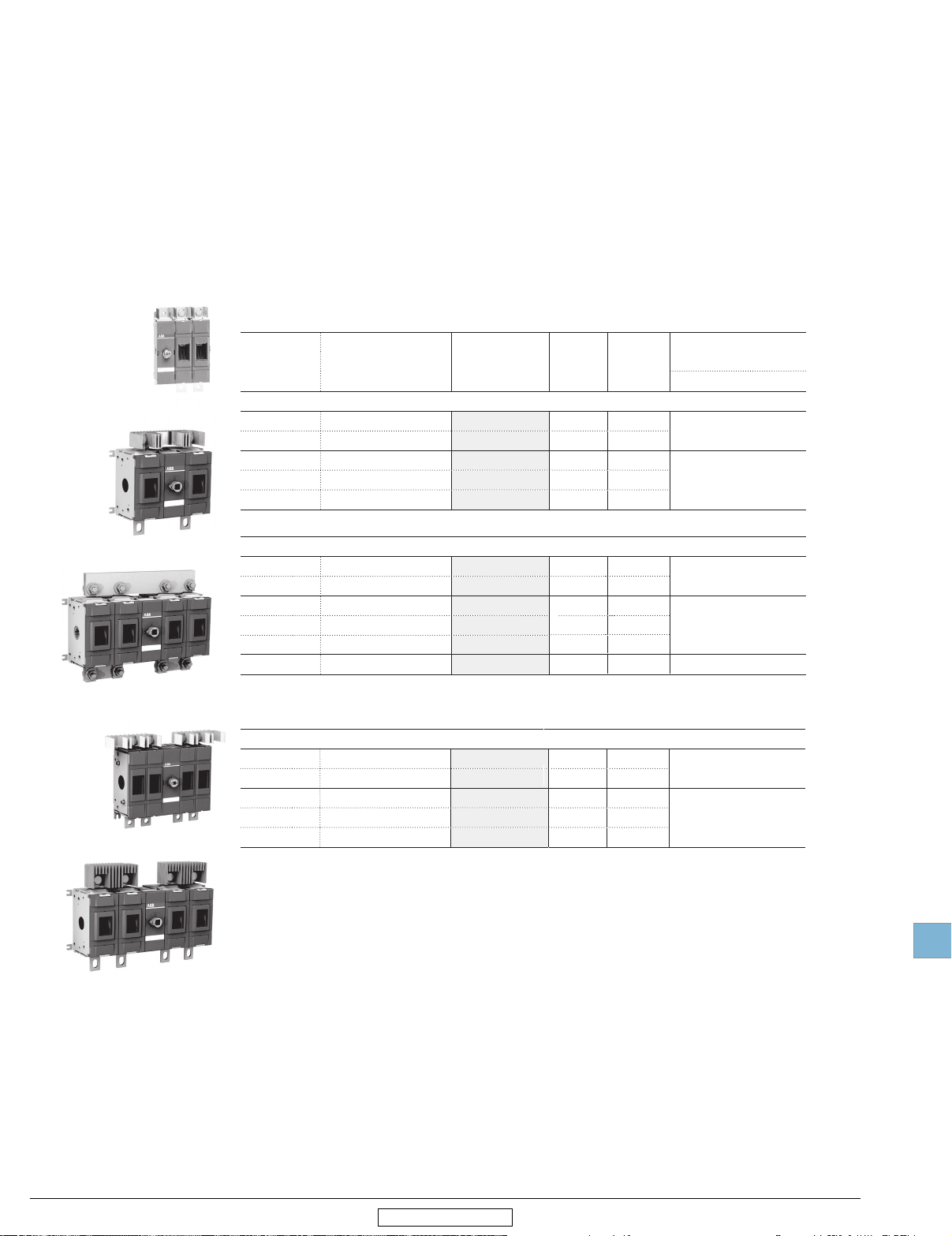
OTDC Solar disconnect switches
100 - 600 A, 1000 VDC
Disconnect
switche
N ble
o usi
n-f
s
OTDC100...200US02
OTDC250...400US11
OTDC_
, base mounting, UL98B
Shafts and handles are not included. Phase barriers are included if mandatory. Included
terminal bolts: OTDC100...200: M8x25 - OTD250...320: M10x30 - OTDC400...600:
M12x40 - Short circuit links/jumpers included and pre-mounted.
Single circuit, 1000 VDC
Number
of
poles
Front operated, mechanism at the end of the switch.
2 100 OTDC100US02
2 200 OTDC200US02
2 250 OTDC250US02
2 320 OTDC320US02
2 400 OTDC400US02
Front operated, mechanism between the poles.
2 100 OTDC100US11
2 200 OTDC200US11
2 250 OTDC250US11
2 320 OTDC320US11
2 400 OTDC400US11
2 600 OTDC600USPP22
Rating [A]
UL98B / 1000 V
atalogue
C
Number
Handle
& Shaft
diam.
6 mm
6 mm
12 mm
12 mm
12 mm
6 mm
6 mm
12 mm
12 mm
12 mm
12 mm
Weight
(lbs)
2.65
2.65
9.70
9.70
9.70
2.65 OHB80L6 / OTDV250EK
2.65
9.70 OHB145L12 / OTDV400EK
9.70
9.70
17.41
Recommended
handle
Pistol / Direct mount (K)
OHB80L6 / OTDV250EK
OHB145L12 / OTDV400EK
OHB145L12 / OTDV400EK
OTDC600USPP22
OTDC100...180US22
OTDC250...400US22
Side operated versions are also
available, please consult ABB.
Double circuit and load side combining, 1000 VDC
Front operated, mechanism CFUXFFOQPMFT
2x2
2x2
2x2
2x2
2x2
100
180
250
320
400
OTDC100US22
OTDC180US22
OTDC250US2
OTDC320US22
OTDC400US22
6 mm
6 mm
12 mm
12 mm
12 mm
5.51 OHB80L6 / OTDV250EK
5.51
14.55 OHB145L12 / OTDV400EK
14.55
14.55
19
Low Voltage Products & Systems
ABB Inc. • 888-385-1221 • www.abb.us/lowvoltage
Revised January 2015
19.19
1SXU000023C0202 Rev. B
Disconnect
witchess
OTDC250...400USV12
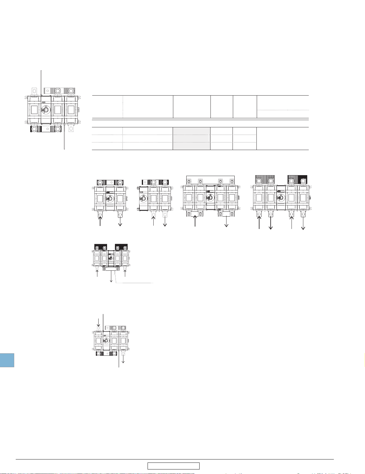
OTDC Solar disconnect switches
250 - 400 A, 1500 VDC
gle circuit, 1500 VDC
Sin
Number
of
poles
Front operated, mechanism CFUXFFOQPMFT
3 250
3
3
Wiring diagrams
1000 VDC
Rating [A]
UL98B / 1500 V
320
400
atalogue
C
Number
I I I I
OTDC250USV12
OTDC320USV12
OTDC400USV12
Handle
& Shaft
diam.
12 mm
12 mm
12 mm
Recommended
Weight
(lbs)
12.56 OHB145L12 / OTDV400EK
12.56
12.56
handle
Pistol / Direct mount (K)
1~
~1111111~~
~ lr!~
I
IIII
III~~~
19
+(-)
OTDC_US11
+(-)
+(-)
1 2
1+2
LOAD
OTDC250...400US22
1500 VDC
+(-)
OTDC250...400USV12
+(-)
OTDCKIT400B101 for OTDC250...400US22, to be ordered separately
+(-)
+(-)
OTDC_US02
+(-)
+(-) +(-)
+(-)
OTDC600USPP22
+(-)
1 21 2
+(-) +(-)
OTDC100...400US22
+(-)
19.B Low Voltage Products & Systems
1SXU000023C0202 Rev. B
Revised January 2015 Revised January 2014
ABB Inc. • 888-385-1221 • www.abb.us/lowvoltage
Disconnect
switches
Fusible
19
Revised January 2015
Fusible disconnect switches
30 – 1200 A, 600 VAC
Fusible
Low Voltage Products & Systems
ABB Inc. • 888-385-1221 • www.abb.us/lowvoltage
Disconnect switches
ABB disconnect switch family includes seven different amperage sizes from 30A to
1200A. All ABB fusible switches are designed to meet customer requirements in terms of
high interrupting capacity and long electrical life while occupying only little more panel
space than the appropriate fuses. The basic construction provides flexibility and high
performance in an extremely compact size. ABB's disconnects are a perfect choice to
withstand the heat and humidity of the tropics, the extreme cold of the arctic and any
rugged industrial environment you may have.
International acceptance
ABB fusible switches are available with a wide range of fuse clip options:
USA CSAUL Canada
Europe BSDIN United Kingdom
NFC France Ultra-rapid
As well as the corresponding approvals: UL listed, CSA approved, IEC rated, CE marked,
and most other international standards.
UL98 (CSA 22.2 No.4) — UL File # E101914, CSA File #58077
For OS30 – 1200 switches, OH__ pistol grip handles
Suitable for use as motor disconnects or industrial control panel disconnects on service
entrance equipment, panelboards, switchboards, industrial control equipment, motor
control centers, etc. Horsepower and ampere rated.
IEC
Tested in accordance to IEC 60947-1 and 3
CE
Compliance with the European Machine Directive IEC/EN 60204
For a complete offer including other standards such as IEC, BS etc, visit:
http://new.abb.com/low-voltage/products/switches
1SXU000023C0202 Rev. B
19.20
Disconnect
switches
Fusible
19
Revised January 2015
Selection guide
OS30 – 1200
OS30FA_12 OS60GJ03 OS100GJ03 OS200J03 OS400J03 OS600J03 OS800L3 OS1200L03
Catalog number 3 pole OS30FACC12 OS30FAJ12 OS60GJ12 OS100GJ03 OS200J03 OS400J03 OS600J03 OS800L3 OS1200L03
General purpose
amp rating
Approvals 1
Technical ratings
(UL,CSA)
Max operating voltage V 600 600 600 600 600 600 600 600 600
Max horsepower rating
Three phase
Single phase
UL fuse class CC J J J J J J L L
Technical ratings (IEC)
Rated insulation and operational
voltage. AC20 and DC20 V 1000 1000 1000 1000 1000 1000 1000 1000 1000
Rated thermal current, I
AC 20/DC 20 open A 32 32 63 160 200 400 630 800 1250
AC 20/DC 20 enclosed A 32 32 63 160 200 400
AC 21A ≤500V A 32 32 63 160 200 400 630 800 1250
Rated operational power AC23
Physical characteristics
Weight 3 pole switch lb 1.54 1.54 2.86 3.30 5.9 12.56 28.66 37.44 63.93
Dimension 3 pole H in 3.66 3.60 3.94 5.67 6.5 9.29 12.03 12.03 16.7
Accessories
Double break contacts
Fuse cover
Terminal lug kit
Terminal shroud
Auxiliary contact
Shaft/handle diameter 6mm 6mm 6mm 6mm 6mm 12mm 12mm 12mm 12mm
Handle UL/NEMA type
Type 1, 3R, 12
Type 1, 3R, 4, 4X, 12
Recommended pistol handle length 45 - 65
Maximum recommended shaft length 290
Electrical interlock —
240V HP 7.5 7.5 15 30 60 125 200 250 —
480V HP 15 15 30 60 125 250 400 500 —
600V HP 20 20 50 75 150 350 500
120V HP 2 2 — — — — — — —
240V HP 3 3 — — — — — — —
th
≤690V A 32 32 63 160 200 400 630 800 1250
400/415V kW
690V kW
4 pole lb 1.98 1.98 3.52 3.96 7.5 15.21 37.48 46.26 —
Integral Integral Integral OZXA-24 OZXA-200 OZXA-400 OZXA-800 OZXA-800 OZXA-1200
Not required Not required Not required
A 30 30 60 100 200 400 600 800 1200
2 pole N/A N/A
3 pole UL98 & IEC UL98 & IEC UL98 & IEC UL98 & IEC UL98 & IEC UL98 & IEC UL98 & IEC UL98 & IEC UL98 & IEC
4 pole UL98 & IEC UL98 & IEC UL98 & IEC UL98 & IEC UL98 & IEC UL98 & IEC UL98 & IEC UL98 & IEC
15 15
22
W in 4.15 4.15 5.63 7.07 7.1 10.04 13.86 13.86 16.42
D in 4.10 4.10 5.04 5.10 5.2 6.93 9.18 9.18 11.62
S S S S S S S S S
S S S S S S S S S
22
• • • • • • • • •
.24 x .24" .24 x .24" .24 x .24" .24 x .24" .24 x .24" .47 x .47" .47 x .47" .47 x .47" .47 x .47"
• • • • • • • • •
• • • • • • • • •
mm
mm
45 - 65
290
—
mm
UL98 & IEC
mm
45 - 65mm 45 - 65
UL98 & IEC UL98 & IEC UL98 & IEC UL98 & IEC UL98 & IEC UL98 & IEC
500
570
30
55
75
132 200 400
110
230
355
630 710
720
450
• • • • • •
mm
290
— — — • • • •
290
mm
mm
65 - 80
290
mm
mm
125 - 175
535
mm
mm
125 - 175
535
mm
125 - 175mm125 - 175
mm
535
mm
UL98 & IEC
—
1000
560
1000
mm
535
mm
S = Standard
• = Available
— = Not available
1 UL listed switches are also listed for CSA Standards.
19.21
1SXU000023C0202 Rev. B
Low Voltage Products & Systems
ABB Inc. • 888-385-1221 • www.abb.us/lowvoltage
Disconnect
switches
Fusible
19
Revised January 2015
Selection information
Standard part number designation 1
Fusible OS Switches (30A)
OS 30 F A J 22 F
Amperage
30 = 30 amps
Fuse Type/Class
J = Class J fuse compatible CC= Class CC fuse compatible
Number of poles and placement of the mechanism
12 = 1 Pole to the left of mechanism, 2 poles to the right of mechanism
22 = 2 Poles to the left of mechanism, 2 poles to the right of mechanism
Fusible OS Switches (60 to 100A)
OS 100G J 03
Amperage
60 = 60 amps 100 = 100 amps
I
1'---------+----1
Fusible OS Switches (200A and above)
Fuse Type/Class
J = Class J fuse compatible
Number of poles and placement of the mechanism
03 = 3 Poles to the right of mechanism 04 = 4 poles to the right of mechanism
OS 200 J 04 F
Pistol Handles
O H B 65 J 6 E011
Amperage
200 = 200 amps 400 = 400 amps 600 = 600 amps 800 = 800 amps 1200 = 1200 amps
Fuse Type/Class
J = Class J fuse compatible
L = Class L fuse compatible
Number of poles and placement of the mechanism
03 = 3 Poles to the right of mechanism
12 = 1 Pole to left of mechanism, 2 poles to right
30 = 3 Poles to the left of mechanism
Handle Color
B = Black Y = Red/Yellow M = Stainless Steel
Handle Length
65 = 65mm 80 = 80mm
Environmental Rating
J = Nema 1, 3R, 12 L = Nema 1, 3R, 12, 4, 4X
Shaft Diameter
6 = 6mm 12 = 12mm
Special Configuration
Blank = for disconnect switches, fusible and non-fusible
E011 = 3 position double throw handle
EH = Stainless Steel Hasp
125 = 125mm 145 = 145m 175 = 175mm 274 = 274mm 330 = 330mm
04 = 4 poles to the right of mechanism
22 = 2 Poles to left of mechanism, 2 poles to right
1 Part designation keys are provided for reference only. Not all variations or configurations a e available.
Low Voltage Products & Systems 19.21
ABB Inc. • 888-385-1221 • www.abb.us/lowvoltage
1SXU000023C0202 Rev. B
Disconnect
switches
Fusible
19
Revised January 2015
Base & DIN rail mounted
30 – 1200 A, UL fuse class CC, J and L
For a complete assembly, please select
one of each:
1 switch (page 19.22)
1 handle (page 19.30)
1 shaft (page 19.32)
1 terminal lug kit (page 19.34)
NOTE: For additional accessories, see
pages 19.29 - 19.40.
Switch
OS_
+
Handle
OH_J_
+
Shaft
OXP_X_
+
Lug Kit
OZXA_
OS30FA_12
OS
60GJ03
OS100GJ12
UL 98
UL general purpose amp
rating
30
60 J
100 J
200 J OS200J02
400 J OS400J02
600 J OS600J02 OS600J03 OS600J04F
800 L OS800L02 OS800L03 OS800L04F
1200 L OS1200L02 OS1200L03 OS1200L04F
UL Fuse Type 600V
J
CC
2 Pole 3 Pole 4 Pole
Catalog number
—
—
OS60GJ02
OS100GJ02
Catalog number
OS30FAJ12
OS30FACC12
OS60GJ12
OS60GJ03
OS100GJ12
OS100GJ03
OS200J03
OS200J30
OS200J12
OS400J03
OS400J30
OS400J12
Catalog number
OS30FAJ22F
OS30FACC22F
OS60GJ04F
OS100GJ04F
OS200J04F
OS400J04F
OS200...1200_03
1 For OS60 and OS100, please add the accessory OSGZD1 in order to mount on a DIN rail. OS200 and above are screw mounted only.
Lugs only required for OS100 and above.
2 Rejection style fuses only
19.22 Low Voltage Products & Systems
1SXU000023C0202 Rev. B
ABB Inc. • 888-385-1221 • www.abb.us/lowvoltage
Disconnect
switches
Fusible
19
Revised January 2015
For a complete assembly,
please select one of each:
1 switch
1 handle
1 shaft
1 terminal lug
Special configurations
Side operated
30 – 100 A, UL fuse class CC and J
+
+
OS60GJS30
OS100GJS30
OXP6X_
Switch
OS_
Handle
OH_J_
Side operated fusible disconnects — 3 poles
UL
general
purpose
amp rating
30 J 5 7.5 7.5 15 20 1.54 OS30FAJS30
30
60 J 15 15 15 30 50 3.52 OS60GJS30
100 J1 25 25 30 60 75 3.97 OS100GJS30
UL
fuse
type
600V
CC
200V 208V 240V 480V 600V
5 7.5 7.5 15 20 1.54 OS30FACCS30
Maximum horsepower rating
Three phase
Weight
(Lbs.)
Handles
UL/NEMA
type
For use with OS30FA_S_, OS60GJS_ & OS100GJS_
1, 3R, 12 IP65
For use with OS60GJS_ & OS100GJS_
1, 3R, 12 IP65
IEC type Color
I I ·
Black
Red/Yel OHY65J6E00S
Black
Red/Yel
Length
(Inches/mm)
2.6/65 OFF/ON Yes Ye s 0.29
3.1/80 OFF/ON Yes Ye s 0.30 OHB80J6E00S
Marking Defeatable Padlockable Weight
I
I I I I
OHB65J6E00S
Shaft
For use with:
OS30FA_S_, OS60GJS_
& OS100GJS_
Length
(Inches/mm)
6.7/170 0.08 OXP6X170
8.3/210 0.10 OXP6X210
Description
.24 x .24” (6 x 6mm)
.24 x .24” (6 x 6mm)
Weight
(Lbs.)
Shaft
OXP_X_
Catalog
number
Catalog
number
Catalog
number
Terminal lug kits
For use with:
OS30FA_S_
OS60GJS_
OS100GJS_
OZXA-24
1 For OS60 and OS100, please add the accessory OSGZD1 in order to mount on a DIN rail.
Lugs only required for OS100.
2 Rejection style fuses only
Low Voltage Products & Systems 19.23
ABB Inc. • 888-385-1221 • www.abb.us/lowvoltage
Wire
size
#18 – 8 — Cu — Integral
#14 – 4 — Cu — Integral
#14 – 2/0 0.43 Cu/Al 6 OZXA-24
I I I I I
Weight
Wire
type
Lugs
per kit
Catalog
number
1SXU000023C0202 Rev. B
 Loading...