

Page 1
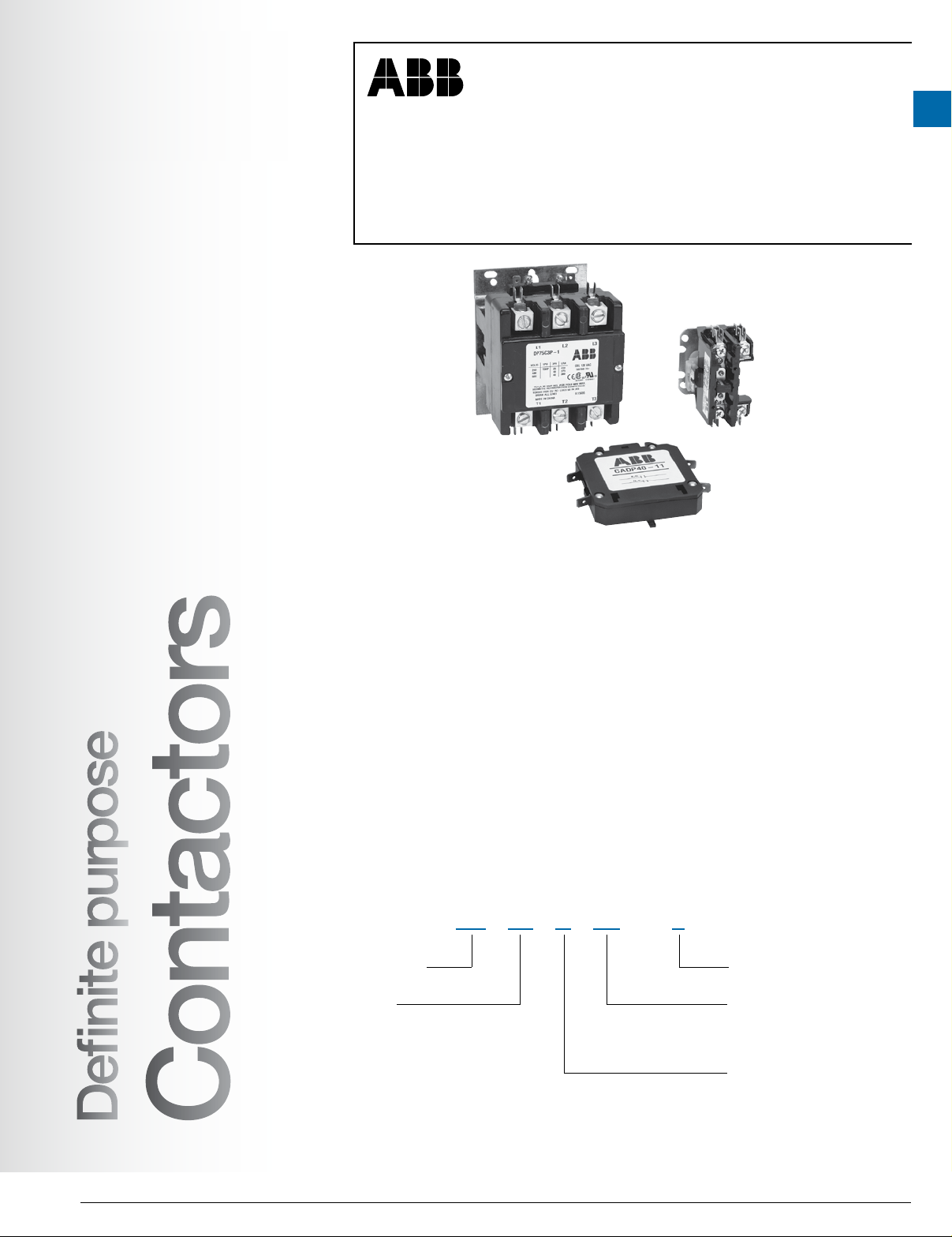
Definite purpose contactors
For applications up to 90 FLA
Definite purpose
contactors
1
Applications
Type DP contactors provide high performance with
exibility and reliability, designed to match numerous
applications including:
• Motors
• Power supplies
• Food service equipment
• Compressors
• Business machines
• Resistive heating
• Air conditioning
• Refrigeration equipment
• Welding
Agency approvals
• UL 508 Guide No. NLDX2, File # E224401
• CSA C22.2 No. 221260 (1456104)
Class 3211 04 / 3211 84
• CE/Semko Certied, EN60947-4-1:2001
Catalog number explanation
DP 30 C 3P - 1
Definite purpose
Frame size
20 = 20A
25 = 25A
30 = 30A
40 = 40A
50 = 50A
60 = 60A
75 = 75A
Definite purpose
Contactors
90 = 90A
Features
• Available as:
– 20A, 25A,1, 2 or 3 pole
– 30A, 1, 2, 3 or 4 pole
– 40A, 2, 3 or 4 pole
– 50-90A, 3 pole
• Industry standard mounting plate provides easily
accessible mounting holes
• Coil terminals are provided with #6-32 screws and
(1) .250 quick connect or dual .250 quickconnect
terminals
• Exclusive hex, slotted, phillips #10-32 terminal
screws for main terminals
• Coil is class B (130° C) insulation system with a wide
range of voltages and 50/60 Hz ratings
• Double E magnet assembly provides optimal
performance with reduced power consumption
• Snap-in auxiliary switch with 1 SPDT or 2 SPDT
contacts available as an option
• 1 N.O. & 1 N.C. auxiliary contact block with 600 VAC
rating available as an option
• Base assembly is made from high arc-resistant
polyesterplastic
Coil voltage
(See coil voltage selection chart)
Power poles
1P = 1 N.O.
2P = 2 N.O.
3P = 3 N.O.
4P = 4 N.O.
Contactor type
C = Non-reversing
Low Voltage Products & Systems 1.175
ABB Inc. 1SXU000023C0202 Rev. A
Page 2
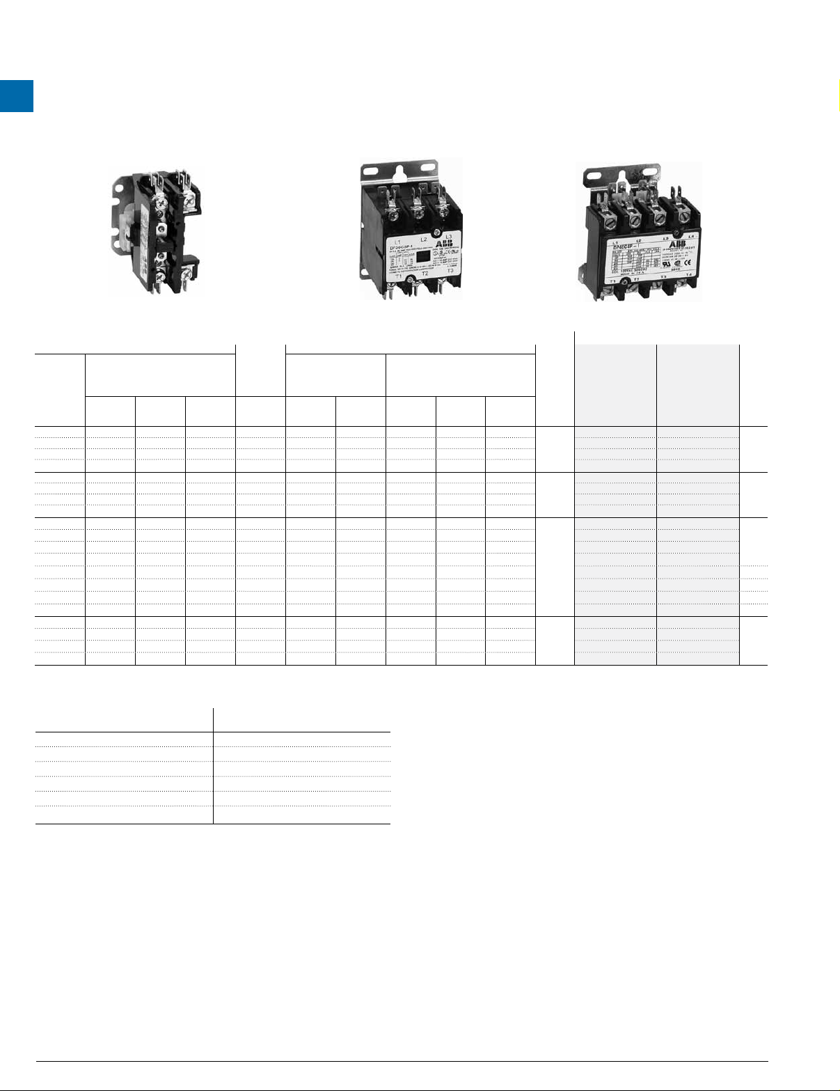
DP non-reversing 1, 2, 3 & 4 pole
1
Definite purpose
contactors
DP20C1P… DP20C3P… DP40C4P
DP40C1P DP30C3P
Electrical ratings Electrical ratings
AC denite purpose controller ratings
Full
load
amperes
(FLA)
20 120 100 80 30 - - - - 25 150 125 100 35 - - - - - DP25C1P-Δ DP25C1P-Δ/B
30 180 125 100 40 - - - - - DP30C1P-Δ DP30C1P-Δ/B
40 240 160 120
20 120 100 80 30 - - - - 25 150 125 100 35 - - - - - DP25C2P-Δ DP25C2P-Δ/B
30 180 125 100 40 - - - - - DP30C2P-Δ DP30C2P-Δ/B
40 240 160 120
Locked rotor Amperes,
breaking all lines (LRA) 1
220…240 /
277V
440…
480V
20 120 100 80 30 1.5 3 7.5 7.5 7.5
25 150 125 100 35 2 5 7.5 15 20 DP25C3P-Δ DP25C3P-Δ/B
30 180 150 120 40 2 5 10 15 20 DP30C3P-Δ DP30C3P-Δ/B
40 240 200 160
50
300 3
60
360 3
75
450 3
90
540 3
20 120 100 80 30 1.5 3 7.5 7.5 7.5
250 200 65 3
300 240 75 5
375 300 90 5 15
450 360 120 7.5 20
25 150 125 100 35 2 5 7.5 15 20 DP25C4P-Δ DP25C4P-Δ/B
30 180 150 120 40 2 5 10 15 20 DP30C4P-Δ DP30C4P-Δ/B
40 240 200 160
Note: 1-pole devices in 2-pole frame with shunt included.
For denite purpose applications up to 90 FLA
AC operated coils
AC motor ratings, breaking all lines (hp)
Single phase Three phase
110…
120V
220…
240V
220…
240V
440…
480V
550…
600V
N.O.
power
poles
1
- - - - - DP40C1P-Δ DP40C1P-Δ/B
2
- - - - - DP40C2P-Δ DP40C2P-Δ/B
3 7.5 10 20 25 DP40C3P-Δ DP40C3P-Δ/B
7.5 6 15 6
10 6 25 6
25 6
30 6
25 25 DP50C3P-Δ 30 30 DP60C3P-Δ 40 40 DP75C3P-Δ 50 50 DP90C3P-Δ -
3
4
3 7.5 10 20 25 DP40C4P-Δ DP40C4P-Δ/B
550…
600V
AC
resistance
air heating,
per pole
(A)
600V 2
50 4
50 4
50 5
50 5
Catalog
number
DP20C1P-Δ DP20C1P-Δ/B
DP20C2P-Δ DP20C2P-Δ/B
DP20C3P-Δ DP20C3P-Δ/B
DP20C4P-Δ DP20C4P-Δ/B
Catalog
number
(bulk pack)
Bulk
qty.
50
50
25
-
-
-
-
25
Coil voltage selection chart (Δ)
Control circuit
voltage
24V 60 Hz F
120V/60 1
Control circuit
voltage
DP ratings for AF & AS/ASL
ABB has additionally performed denite purpose testing for air conditioning
(h.r.c.) applications with AF and AS/ASL series contactors. Please contact
Technical Support regarding the use of these devices for applications
20…900 FLA, 80…5600 LRA.
208/240V AC 2
277V AC C
480V AC 4
575/600V 60 Hz 6
1 1- & 2-pole devices rated per pole
2 DP20…DP30 intended for single phase resistive applications only above 277V
3 220…240V only
4 Max. 277V
5 Breaking all lines
6 Suitable at 208V
1.176 Low Voltage Products & Systems
1SXU000023C0202 Rev. A ABB Inc.
Page 3
Definite purpose
Accessories
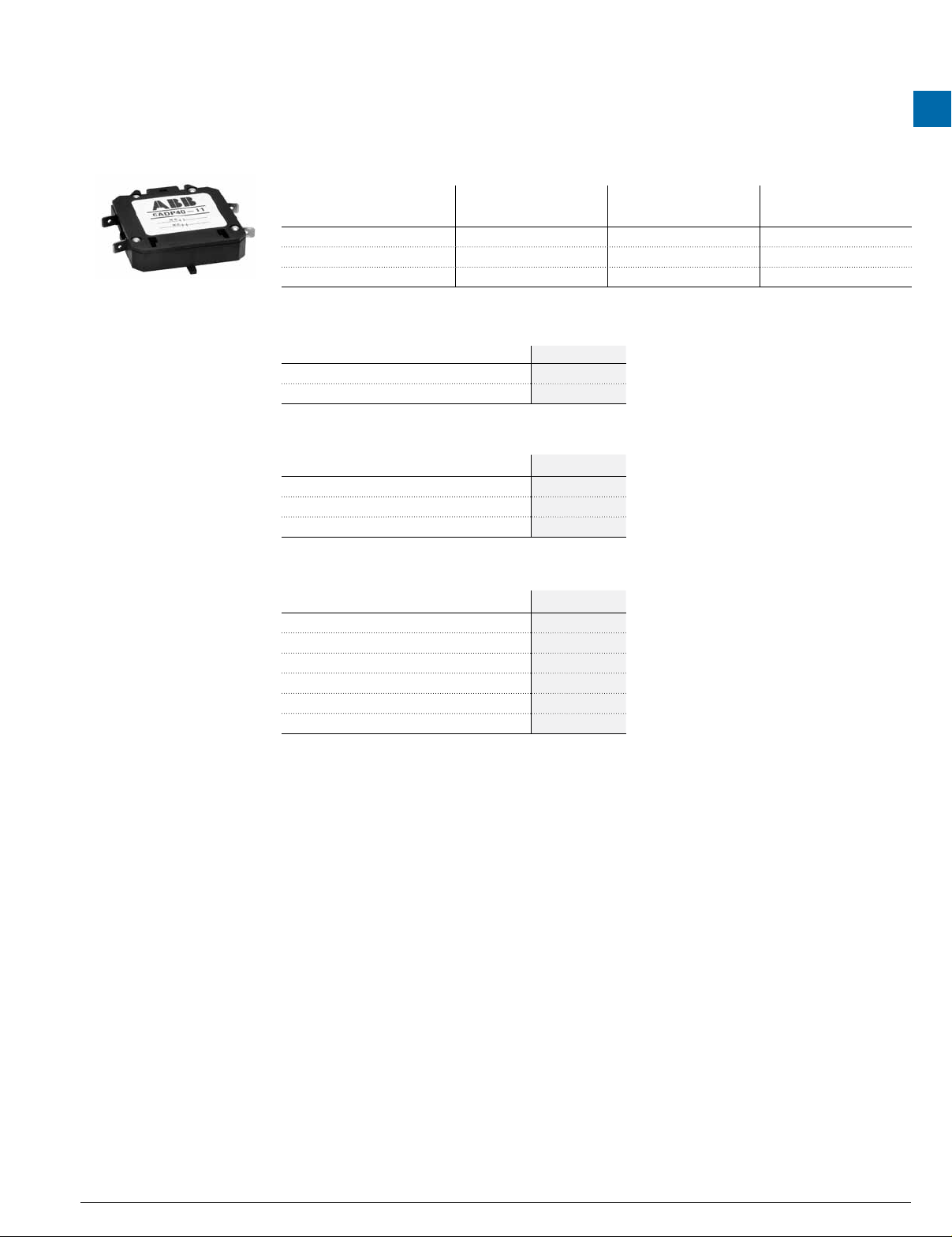
Auxiliary contact blocks
Description
Form C SPDT CADP40-10 CADP40-10 -
Double Form C SPDT CADP40-20 CADP40-20 -
Form Z SPDT (1NO & 1NC)** CADP40-11 CADP40-11 CADP90-11
** Must be the same polarity on both poles. For a complete description on contact types, please refer to page 1.78.
Mechanical interlock
Application Catalog number
DP30C3P-* VMDP-1
DP40C3P-* VMDP-1
Protective cover
Application Catalog number
DP20C2P-* DP-2-AC
DP25C2P-* DP-2-AC
DP30C2P-* DP-2-AC
DP20 to DP40, 3 pole and 4 pole
congurations
DP50 to DP60 DP75 to DP90"
contactors
1
Din-rail mounting bracket
Application Catalog number
DP20C1P-* DP/DIN1-2
DP25C1P-* DP/DIN1-2
DP30C1P-* DP/DIN1-2
DP20C2P-* DP/DIN1-2
DP25C2P-* DP/DIN1-2
DP30C2P-* DP/DIN1-2
Note: Replace “*” with appropriate coil voltage as per
previous page
Low Voltage Products & Systems 1.177
ABB Inc. 1SXU000023C0202 Rev. A
Page 4

1
Definite purpose
contactors
Technical data
Contact rating of SPDT auxiliary contacts
Voltage Current rating
125 VAC 10 A, 1/3 HP
120 VAC 4 A on lamp load
250 VAC 10 A, 1/3 HP
125 VDC 0.5 A
250 VDC 0.25 A
Contact rating of 1 N.O. & 1 N.C. auxiliary contacts
120V 240V 480V 600V
Break (A) 3.0 1.5 0.75 0.6
Make (A) 30 15 7.5 6
Continuous (A) 10 10 10 10
DP20 to DP40, 1 & 2 poles
Coil technical data DP20 to DP30, 1 pole DP20 to DP40, 2 poles
Nominal coil voltage 24 120 208/240 277 24 120 208/240 277
Maximum pickup volts 18 88 177 221 18 88 177 221
Drop out volts range 6 - 15 20 - 70 40 - 140 50 - 165 6 - 15 20 - 70 40 - 170 50 - 165
Nominal inrush VA 50 Hz 31 31 31 31 33 33 33 33
Nominal inrush VA 60 Hz 28 28 28 28 30 30 30 30
Nominal closed VA 50 Hz 6 6 6 6 8 8 8 8
Nominal closed VA 60 Hz 5 5 5 5 6.5 6.5 6.5 6.5
Nominal coil resistance Ohms 18 420 1800 2500 11 237 1000 1600
Other specifications
Specications DP20 to DP30, 1 and 2 poles DP40, 2 poles
Line and load terminals # 10 - 32 screw Box lug
Wire size AWG (min - max) 16 - 8 14 - 4 Cu/Al
Tightening torque (recommended) 25 in. lbs. 40 in. lbs.
Coil terminals Dual .250” QC Dual .250” QC
Power Terminals
Covers Optional Standard
Insulation System 130
1 Pole: Quad .250” QC Quad
2 Pole: Dual or Quad .250” QC Dual or quad
o
C class B 130
o
C class B
DP20 to DP60, 3 poles
Coil technical data DP20 to DP40, 3 poles DP50 to DP60, 3 poles
Nominal coil voltage 24 120 208/240 277 480 24 120 208/240 277 480
Maximum pickup volts 18 88 177 220 384 18 88 177 220 374
Drop out volts range 6 - 15 20 - 70 40 - 140 50 - 140 150 - 270 6 - 15 20 - 70 40 - 140 50 - 185 150 - 286
Nominal inrush VA 50 Hz 65 65 65 65 65 62 62 62 62 62
Nominal inrush VA 60 Hz 60 60 60 60 60 59 59 59 59 59
Nominal closed VA 50 Hz 7.5 7.5 7.5 7.5 7.5 9 9 9 9 9
Nominal closed VA 60 Hz 6 6 6 6 6 7 7 6 7 7
Nominal coil resistance Ohms 7 180 720 900 1320 2.4 150 600 750 1452
Other specifications
Specications DP20 to DP30, 3 poles DP40, 3 poles DP50 to DP60, 3 poles
Line and load terminals
Wire size AWG (min - max) 16 - 8 2 14 - 4 Cu/Al 14 - 2 Cu/Al
Tightening torque (recommended) 22 in. lbs. 40 in. lbs. 50 in. lbs.
Quick connects (power terminals) Dual .250 QC Dual .250 QC Dual .250 QC
Coil terminals
Covers Standard Standard Standard
Insulation system 130
1 See diagram on page 1.183 for approximate dimensions and description.
2 Stranding must be split for # 8 wire.
# 10 - 32 screw
Dual .250 QC
o
C class B 130o C class B 130o C class B
1.178 Low Voltage Products & Systems
1SXU000023C0202 Rev. A ABB Inc.
1 Box lug 1 Box lug 1
2 Dual .250 QC 2 # 6 - 32 screw & dual .250 QC 2
Page 5

Definite purpose
Technical data
contactors
DP20 to DP40, 4 poles
Coil technical data DP20 to DP40, 4 poles
Nominal coil voltage 24 120 208/240 277 480
Maximum pickup volts 18 88 177 220 384
Drop out volts range 6 - 15 20 - 70 40 - 140 65 - 185 150 - 270
Nominal inrush VA 50 Hz 62 62 62 62 62
Nominal inrush VA 60 Hz 59 59 59 59 59
Nominal closed VA 50 Hz 9 9 9 9 9
Nominal closed VA 60 Hz 7 7 6 7 6
Nominal coil resistance Ohms 6 148 600 750 2100
Other specifications
Specications DP20 to DP30, 4 poles DP40, 4 poles
Line and load terminals
Wire size AWG (min - max) 16 - 8 2 14 - 4 Cu/Al
Tightening torque (recommended) 22 in. lbs. 40 in. lbs.
Quick connects (power terminals) Dual .250 QC Dual .250 QC
Coil terminals
Covers Standard Standard
Insulation system 130
# 10 - 32 screw 1 Box lug 1
Dual .250 QC 2 Dual .250 QC 2
o
C class B 130o C class B
1
DP75 to DP90, 3 poles
Coil technical data DP75 to DP90, 3 poles
Nominal coil voltage 24 120 208/240 277 480
Maximum pickup volts 18 88 177 220 384
Drop out volts range 6-15 20-70 40-10 65-185 150 - 270
Nominal inrush VA 50 Hz 285 285 285 285 62
Nominal inrush VA 60 Hz 240 240 240 240 59
Nominal closed VA 50 Hz 42 42 42 42 9
Nominal closed VA 60 Hz 27 27 27 27 6
Nominal coil resistance Ohms 0.65 16 64 85 2100
Other specifications
Specications DP75 to DP90, 3 poles
Line and load terminals Box lug (1)
Wire size AWG (min-max) 14-1 Cu/Al
Tightening torque (recommended) 50 in. lbs
Quick connects (power terminals)
Coil terminals Dual .250" QC
Covers Standard
Insulation system 130°C Class B
Dual .250" QC
1 See diagram on page 1.183 for approximate dimensions and description.
2 Stranding must be split for # 8 wire.
Low Voltage Products & Systems 1.179
ABB Inc. 1SXU000023C0202 Rev. A
Page 6

1
Definite purpose
contactors
DP20 to DP30, 1 pole
DP20 to DP30, 2 poles
Approximate dimensions
DP20 to DP30, 3 poles
1.180 Low Voltage Products & Systems
1SXU000023C0202 Rev. A ABB Inc.
Page 7

Definite purpose
DP30, 4 poles
DP40, 2 poles
Approximate dimensions
2.75
contactors
1
DP40, 3 poles
Low Voltage Products & Systems 1.181
ABB Inc. 1SXU000023C0202 Rev. A
Page 8

1
Definite purpose
contactors
DP40, 4 poles
DP50 to DP60, 3 poles
Approximate dimensions
DP75 to DP90, 3 poles
3.75
.20
4.05
5.00
3.75
1.182 Low Voltage Products & Systems
1SXU000023C0202 Rev. A ABB Inc.
2.50
2.90
4.62
Page 9

Definite purpose
Approximate dimensions
Terminals
Standard on DP 20 to DP30 Standard on DP40 Standard on DP 60 Standard on DP 90
contactors
1
Low Voltage Products & Systems 1.183
ABB Inc. 1SXU000023C0202 Rev. A
 Loading...