

ABB DCS550 Manual REv e
DCS550
Manual
DCS550 Drives (20 A to 1000 A)

DCS550 Manuals
Public. number
E D I
ES F CN
RU
Quick Guide
3ADW000395
x x x x x
DCS550 Tools & Documentation CD
3ADW000377
x
DCS550 Modules
DCS550 Flyer
3ADW000374
x x x x
DCS550 Technical Catalog
3ADW000378
x x x
DCS550 Manual
3ADW000379
x x x x
DCS550 Service Manual
3ADW000399
x
Installation according to EMC
3ADW000032
x
Technical Guide
3ADW000163
x
Extension Modules
RAIO-01 Analog IO Extension
3AFE64484567
x
RDIO-01 Digital IO Extension
3AFE64485733
x
Serial Communication
RPBA-01 PROFIBUS
3AFE64504215
x
RCAN-01 CANopen
3AFE64504231
x
RCNA-01 ControlNet
3AFE64506005
x
RDNA-01 DeviceNet
3AFE64504223
x
RMBA-01 MODBUS
3AFE64498851
x
RETA-01 Ethernet
3AFE64539736
x
Status 11.2013
DCS550 Manuals list f.doc
Language
3ADW000379R0501 DCS550 Manual e e
Safety instructions
Dangerous voltage warning warns of high voltage, which can cause physical injury or death
and/or damage to the equipment.
General danger warning warns about conditions, other than those caused by electricity, which
can result in physical injury or death and/or damage to the equipment.
Electrostatic sensitive devices warning warn of electrostatic discharge, which can damage
the equipme
WARNING!
1.
•
•
•
•
•
Note:
•
•
•
system from the supply.
Chapter overview
This chapter contains the safety instructions you must follow when installing, operating and servicing the drive.
If ignored, physical injury or death may follow, or damage may occur to the drive, the motor or driven
equipment. Read the safety instructions before you work on the unit.
To which products this chapter applies
The information is valid for the whole range of the product DCS550.
Usage of warnings and notes
There are two types of safety instructions throughout this manual: warnings and notes. Warnings caution you
about conditions, which can result in serious injury or death and/or damage to the equipment, and advice on
how to avoid the danger. Notes draw attention to a particular condition or fact, or give information on a
subject. The warning symbols are used as follows:
3
nt.
Installation and main t enan ce wor k
These warnings are intended for all who work on the drive, motor cable or motor. Ignoring the instructions can
cause physical injury or death and/or damage to the equipment.
Only qualified electricians are allowed to install and maintain the drive!
Never work on the drive, motor cable or motor when main power is applied. Always ensure
by measuring with a multimeter (impedance at least 1 Mohm) that:
1. Voltage between drive input phases U1, V1 and W1 and the frame is close to 0 V.
2. Voltage between terminals C+ and D- and the frame is close to 0 V.
Do not work on the control cables when power is applied to the drive or to the external
control circuits. Externally supplied control circuits may cause dangerous voltages inside the
drive even when the main power on the drive is switched off.
Do not make any insulation resistance or voltage withstand tests on the drive or drive
modules.
Isolate the motor cables from the drive when testing the insulation resistance or voltage
withstand of the cables or the motor.
When reconnecting the motor cable, always check that the C+ and D- cables are connected
with the proper terminal.
The motor cable terminals on the drive are at a dangerously high voltage when the main
power is on, regardless of whether the motor is running or not.
Depending on the external wiring, dang er ous voltag es ( 115 V, 220 V or 230 V) may be
present on the relay outputs of the drive system (e.g. RDIO).
DCS550 with enclosure extension: Before working on the drive, isolate the whole drive
Safety instructions
4
3ADW000379R0501 DCS550 Manual e e
WARNING!
•
•
ed and marked as required by safety
•
•
Note:
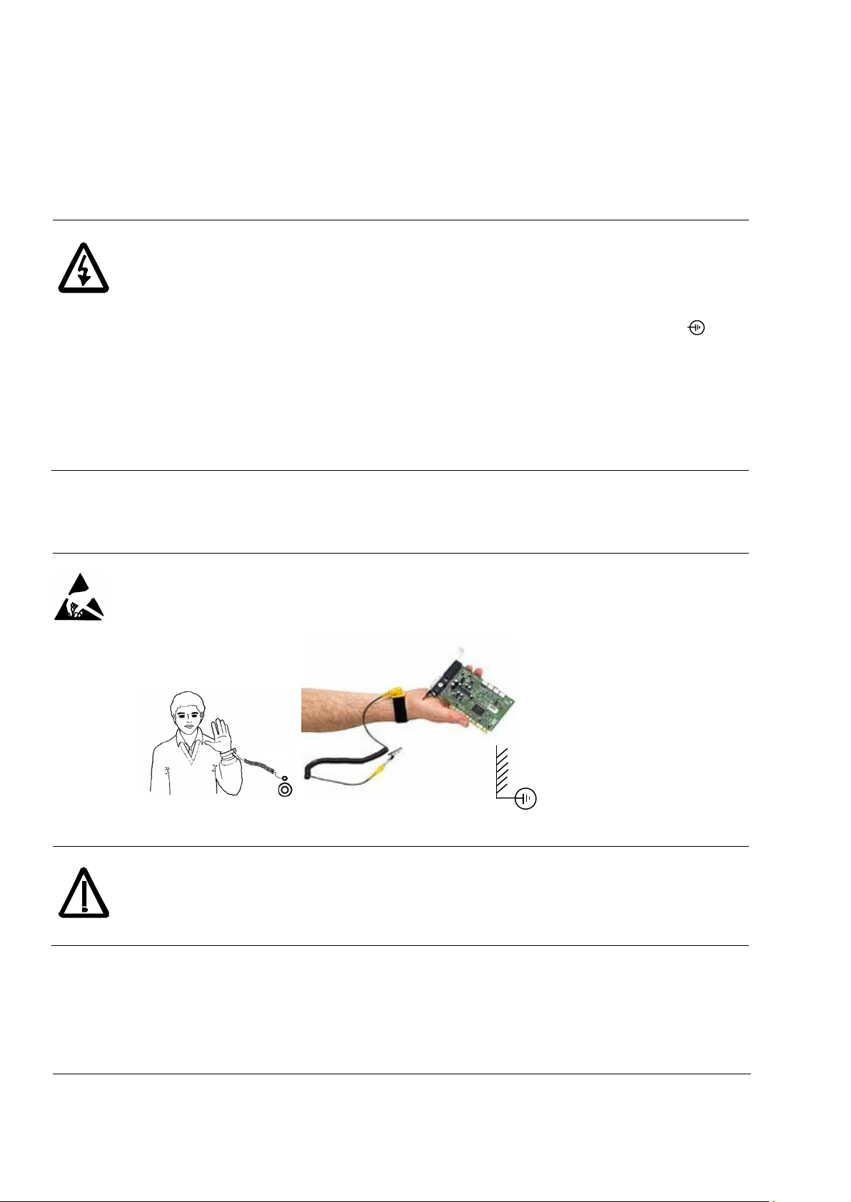
WARNING!
The printed circuit boards contain components sensitive to electrostatic discharge. Wear a
grounding
Use grounding strip:
ABB order no.: 3ADV050035P0001
WARNING!
Handle the fiber optic cables with care. When unplugging optic cables, always grab the
connector, not the cable itself. Do not touch the ends of the fibers with bare
is extremely sensitive
Grounding
These instructions are intended for all who are responsible for the grounding of the drive. Incorrect grounding
can cause physical injury, death and/or equipment malfunction and increase electromagnetic interference.
Ground the drive, motor and adjoining equipment to ensure personnel safety in all
circumstances, and to reduce electromagnetic emission and pick-up.
Make sure that grounding conductors are adequately siz
regulations.
In a multiple-drive installation, connect each drive separately to protective earth (PE ).
Minimize EMC emission and make a 360° high frequency grounding (e.g. conductive
sleeves) of screened cable entries at the cabinet lead-through plate.
Power cable shields are suitable as equipment grounding conductors only when adequately
sized to meet safety regulations.
As the normal leakage current of the drive is higher than 3.5 mAAC or 10 mADC (stated by EN
50178, 5.2.11.1), a fixed protective earth connection is required.
Printed circuit boards and fiber opti c cables
These instructions are intended for all who handle the circuit boards and fiber optic cables. Ignoring the
following instructions can cause damage to the equipment.
wristband when handling the boards. Do not touch the boards unn ec es sar ily.
to dirt. The minimum allowed bend radius is 35 mm (1.38 in.).
hands, as the fiber
Safety instructions
3ADW000379R0501 DCS550 Manual e e
Mechanical installation
WARNING!
WARNING!
Note:
These notes are intended for all who install the drive. Handle the unit carefully to avoid damage and injury.
DCS550 size F4: The drive is heavy. Do not lift it alone. Do not lift the unit by the front cover.
Place it only on its back.
Make sure that dust from drilling does not enter the drive when installing. Electrically
conductive dust inside the unit may cause damage or lead to malfunction.
Ensure sufficient cooling.
Do not fasten the drive by riveting or welding.
Operation
These warnings are intended for all who plan the operation of the drive or operate the drive. Ignoring the
instructions can cause physical injury or death and/or damage to the equipment.
Before adjusting the drive and putting it into service, make sure that the motor and all driven
equipment are suitable for operation throughout the speed range provided by the drive. The
drive can be adjusted to operate the motor at speeds above and below the base speed.
Do not control the motor with the disconnecting device (disconnecting mains); instead, use
5
the control panel keys
Mains connection
You can use a disconnect switch (with fuses) to disconnect the electrical components of the
drive from the mains for installation and maintenance work. The type of disconnect switch
used must be as per EN 60947-3, Class B, so as to comply with EU regulations, or a circuit-
breaker type which switches off the load circuit by means of an auxiliary contact causing the
breaker's main contacts to open. The mains disconnect must be locked in its "OPEN"
position during any installation and maintenance work.
EMERGENCY STOP buttons must be installed at each control desk and at all other control
panels requiring an emergency stop function. Pressing the STOP button on the control panel
of the drive will neither cause an emergency stop of the motor, nor will the drive be
disconnected from any dangerous potential.
To avoid unintentional operating states, or to shut the unit down in case of any imminent
danger according to the standards in the safety instructions it is not sufficient to merely shut
down the drive via signals "RUN", "drive OFF " or "Em ergency Stop" respectively "control
panel" or "PC tool".
Intended use
The operating instructions cannot take into consideration every possible case of
configuration, operation or maintenance. Thus, they mainly give such advice only, which is
required by qualified personnel for normal operation of the machines and devices in industrial
installations.
If in special cases the electrical machines and devices are intended for use in non-industrial
installations - which may require stricter safety regulations (e.g. protection against contact by
children or similar) - these additional safety measures for the installation must be provided by
the customer during assembly.
When the control location is not set to Local (L not shown in the status row of the display),
the stop key on the control panel will not stop the drive. To stop the drive using the control
and , or commands via the I/O board of the drive.
panel, press the LOC/REM key and then the stop key
.
Safety instructions

6
3ADW000379R0501 DCS550 Manual e e
Table of contents
DCS550 Manuals ................................................................................................................................................. 2
Safety instructions ................................................................................................................................................ 3
Table of contents ................................................................................................................................................. 6
Introduction .......................................................................................................................................................... 8
The DCS550 ........................................................................................................................................................ 9
General ...................................................................................................................................................... 9
Overview Main circuit and control ............................................................................................................ 11
Environmental Conditions ........................................................................................................................ 12
Type code ................................................................................................................................................ 13
Voltage and current ratings ..................................................................................................................... 14
Dimensions and weights .......................................................................................................................... 16
Mechanical installation ....................................................................................................................................... 19
Cabinet installation .................................................................................................................................. 20
Planning the electrical installation ...................................................................................................................... 21
Drive connection and wiring example ...................................................................................................... 22
Installation components ........................................................................................................................... 24
① Line reactors (L1) ................................................................................................................................ 24
② Semiconductor fuses (F1) ................................................................................................................... 25
③ EMC filters (E1) ................................................................................................................................... 25
④ Auxiliary transformer (T2) for converter electronics and fan ............................................................... 28
⑤ Start, Stop and E-stop control ............................................................................................................. 28
⑥ Cooling fans ........................................................................................................................................ 29
Cabling ..................................................................................................................................................... 30
Electrical ins ta ll a ti on .......................................................................................................................................... 34
Power connections .................................................................................................................................. 35
Drive interfaces ........................................................................................................................................ 37
Installation checklist ................................................................................................................................. 39
Electronic board details...................................................................................................................................... 40
Terminal locations.................................................................................................................................... 40
Table of used boards ............................................................................................................................... 41
Control board SDCS-CON-F ................................................................................................................... 42
Power Interfac e boar d SDC S-PIN-F........................................................................................................ 45
Integrated field exciters SDCS-BAB-F01 and SDCS-BAB-F02 .............................................................. 47
Accessories ........................................................................................................................................................ 50
① Line reactors (L1) ................................................................................................................................ 50
② Semiconductor fuses (F1) ................................................................................................................... 56
③ EMC filters (E1) ................................................................................................................................... 58
④ Auxiliary transformer (T2) for converter electronics and fans ............................................................. 58
Start-up .............................................................................................................................................................. 59
Commissioning ........................................................................................................................................ 59
Macros ..................................................................................................................................................... 63
Firmware description .......................................................................................................................................... 74
Table of contents

3ADW000379R0501 DCS550 Manual e e
Start / stop sequences.............................................................................................................................. 74
Excitation .................................................................................................................................................. 75
DC-breaker ............................................................................................................................................... 77
Dynamic braking ....................................................................................................................................... 78
Digital I/O configuration ............................................................................................................................ 80
Analog I/O configuration ........................................................................................................................... 84
Serial field bus communication ........................................................................................................................... 88
CANopen communication with fieldbus adapter RCAN-01 ...................................................................... 88
ControlNet communication with fieldbus adapter RCNA-01 .................................................................... 92
DeviceNet communication with fieldbus adapter RDNA-01 ..................................................................... 95
Ethernet/IP communication with fieldbus adapter RETA-01 .................................................................... 98
Modbus (RTU) communication with fieldbus adapter RMBA-01 ........................................................... 102
Modbus/TCP communication with fieldbus adapter RETA-01 ............................................................... 104
Profibus communication with fieldbus adapter RPBA-01 ....................................................................... 105
ProfiNet communication with fieldbus adapter RETA-02 ....................................................................... 109
Switch on sequence ............................................................................................................................... 110
Data set table ......................................................................................................................................... 110
AP (Adaptive Program) ..................................................................................................................................... 111
What is AP? ............................................................................................................................................ 111
DWL AP .................................................................................................................................................. 116
Function blocks ...................................................................................................................................... 120
7
Winder .............................................................................................................................................................. 132
Winder blocks ......................................................................................................................................... 132
Winder macros ....................................................................................................................................... 139
Signal and parameter list .................................................................................................................................. 153
Signal groups list .................................................................................................................................... 153
Parameter groups list ............................................................................................................................. 154
Signals .................................................................................................................................................... 156
Parameters ............................................................................................................................................. 181
DCS Control Panel ........................................................................................................................................... 270
Fault tracing ...................................................................................................................................................... 276
Converter protection ............................................................................................................................... 276
Motor protection ..................................................................................................................................... 279
Display of status, fault messages and error codes ................................................................................ 285
Fault signals (F) ...................................................................................................................................... 286
Alarm signals (A) .................................................................................................................................... 294
Notices ................................................................................................................................................... 301
Appendix A: Quick start-up diagrams ............................................................................................................... 302
Drive configuration with reduced components ....................................................................................... 302
I/O connections ...................................................................................................................................... 304
Appendix B: Firmware structure diagrams ....................................................................................................... 305
Appendix C: Index of signals and parameters ................................................................................................. 309
Table of contents

8
Introduction
Chapter overview
This chapter describes the purpose, contents and the intended use of this manual.
Before You Start
The purpose of this manual is to provide you with the information necessary to control and program the drive.
Study carefully the S afety i nstr uc tions
the drive. Read this manual before starting-up the drive.
Note:
This manual describes the standard DCS550 firmware.
What this manual contains
The Safety instructions ar e at the beginning of this manual.
Introduction
The DCS550
Mechanical installation
Planning the electrical installation
Electrical ins ta ll a ti on
Electronic b oard det ai ls
Accessories
Start-up
Firmware description
Serial field bus communication
AP (Adaptive Program)
Winder
Signal and parameter list
DCS Control Panel
Fault tracing
Appendix A: Quick start-up diagrams
Appendix B: Firmware structure diagrams
Appendix C: Index of signal and parameters
, the chapter you are currently reading, introduces you to this manual.
, this chapter describes the basic properties of the DCS550.
, this chapter describes the mechanical installation of the DCS550.
, this chapter describes the electrical installation of the DCS550.
, this chapter describes the electronics of the DCS550.
, this chapter describes the accessories for the DCS550.
, this chapter describes the basic start-up procedure of the DCS550.
, this chapter describes how to control the DCS550 with standard firmware.
, this chapter describes the communication capabilities of the DCS550.
, this chapter describes the basics of AP and instructs how to build an application.
, this chapter describes the winder and instructs how to use the winder blocks of the DCS550.
, this chapter contains all signals and parameters.
, this chapter describes the handling of the DCS Control Panel.
, this chapter describes the protections and fault tracing of the drive.
at the beginning of this manual before attempting any work on or with
, this chapter describes how to plan the electrical installation of the DCS550.
Introduction
3ADW000379R0501 DCS550 Manual e e

The DCS550
In order to offer the same after sales service to our customer around the
world, ABB has created the
sales service is globally consistent due to common targets, rules and the
way of operation.
drive service homepage at
Country
Local ABB Service
Town
Service Phone No.
Argentina
Asea Brown Boveri S.A.
BUENOS AIRES
+54 (0) 12 29 55 00
Australia
ABB
NOTTING HILL
+61 (0) 3 85 44 00 00
Austria
ABB AG
WIEN
+43 1 60 10 90
Belgium
ABB N.V.
ZAVENTEM
+32 27 18 64 86
+32 27 18 65 00 - 24h service
Brazil
ABB Ltda.
OSASCO
+55 (0) 11 70 84 91 11
Canada
ABB Inc.
SAINT
+1800 865 7628
China
ABB China Ltd
BEIJING
+86 40 08 10 88 85 - 24h service
Czech Republic
ABB S.R.O.
PRAHA
+42 02 34 32 23 60
Finland
ABB Oy Service
KUUSANKOSKI
+35 8 10 22 51 00
Finland
ABB Oy Product Service
HELSINKI
+35 8 10 22 20 00
Finland
ABB Oy Service
NOKIA
+35 8 10 22 51 40
France
ABB Automation
ABB Process Industry
MONTLUEL
from abroad France
+33 1 34 40 25 81
+0810 02 00 00
Germany
ABB Process Industries
MANNHEIM
+49 18 05 22 25 80
Greece
ABB SA
METAMORPHOSSIS
+30 69 36 58 45 74
Ireland
ABB Ireland Ltd.
TALLAGHT
+35 3 14 05 73 00
Italy
ABB
MILAN
+39 02 90 34 73 91
Korea, Republic
ABB Ltd., Korea
CHONAN
+82 (0) 4 15 29 22
Malaysia
ABB Malaysia Sdn. Bhd.
KUALA LUMPUR
+60 3 56 28 42 65
Mexico
ABB Sistemas S.A. DE C.V.
TLALNEPANTLA
+52 53 28 14 00
Netherlands
ABB B.V.
ROTTERDAM
+31 1 04 07 88 66
New Zealand
ABB Service ltd
AUCKLAND
+64 92 76 60 16
Poland
ABB Centrum IT Sp.zo.o
WROCLAW
LODZ
+48 42 61 34 96 2
+48 42 29 93 91 39 5
Russia
ABB Automation LLC
MOSCOW
+74 95 96 0
Switzerland
ABB AG
DÄTTWIL
+41 5 85 86 87 86
Singapore
ABB Industry Pte Ltd
SINGAPORE
+65 67 76 57 11
Slovakia
ABB Elektro s.r.o.
BANSKA BYSTRICA
+42 19 05 58 12 78
South Africa
ABB South Africa (Pty) Lt
JOHANNESBURG
+27 1 16 17 20 00
Spain
ABB Automation Products
BARCELONA
+34 9 37 28 73 00
Taiwan
ABB Ltd.
TAIPEI 105
+88 62 25 77 60 90
Thailand
ABB Limited
SAMUTPRAKARN
+66 27 09 33 46
Turkey
ABB Elektirk Sanayi A.S
ISTANBUL
+90 2 16 36 52 90
USA ABB Industrial Products
NEW BERLIN
+1 26 27 85 32 00
+1 262 435 7365
Venezuela
ABB S.A.
C
S
+58 (0) 22 38 24 11 / 12
Chapter overview
This chapter describes the basic properties of the DCS550.
General
ABB Drive Service
DRIVE SERVICE CONCEPT. ABB’s after
This means for our customers simply visit the ABB
www.abb.com/drivesservices.
DC drives worldwide Service Network
9
-LAURENT
RC
3ADW000379R0501 DCS550 Manual e e
The DCS550
10
Every DCS550 comes together with a DCS550
Tools CD. This CD contains the documentation
and PC tools for the DCS550.
DCS550 Tools CD
Documentation
The structure of the documentation is according to the following system:
− The DCS550 Technical Catalogue contains information to engineer complete DC drive systems.
− The DCS550 Manual contains information about
1. module dimensions, electronic boards, fans and auxiliary parts,
2. mechanical and electrical installation,
3. firmware and parameter settings
4. start-up and maintenance of the entire drive
5. fault, alarm codes and information for trouble shooting.
− The DCS800 / DCS550 Service Manual contains information for maintenance and repair of the converters.
− Additional information about technical accessories (e.g. hardware extension or fieldbus interfaces) are
handled by separate manuals. See chapter DCS550 Manuals
DCS550 PC tools
After inserting the DCS550 CD all programs and documentation necessary to work with the DCS550 can be
installed. This includes:
− DCS550 documentation,
− DriveWindow Light for parameterization, commissioning and service,
− plug ins for DriveWindow Light (DWL AP and the commissioning wizard)
− Hitachi FDT 2.2 for firmware download and
− DCS550 firmware.
.
The DCS550
3ADW000379R0501 DCS550 Manual e e
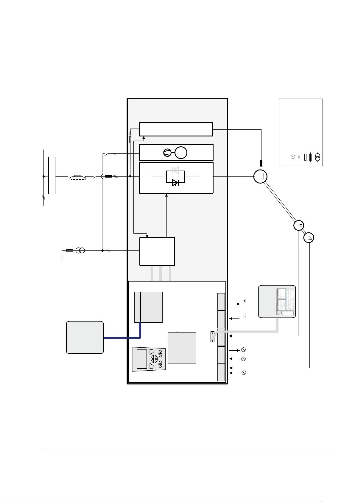
Overview Main circuit and contr ol
K1
T2
Q1
F2
M
F1
525V
525V
SB_550_001_a.ai
230 V / 115 V
L1
K5
(SDCS-BAB-F)
M
DCS550
SDCS-PIN-F
analog input / output
digital input / output
Legend
fuse
reactor
transformer
Slot 3
Slot 1
Fieldbusses,
adapters
R-type
OnBoard fieldexciter
EMC filter
DWL
PC with
8
4
7
3
E
T
SDCS-
CON-F
X1 X2 X3 X4 X5
X9
Panel
X33
X34
RS232
X11
E/A-Adapter R-Typ
PLC
1
DCS550 converter units F1 to F4 for 525 V with integrated field exciters.
11
3ADW000379R0501 DCS550 Manual e e
The DCS550
12
System connection
Environmental limit values
Voltage, 3-phase:
230 to 525 V acc. to IEC 60038
Permissible cooling air temperature
Voltage deviation:
±10 % continuous; ±15 % shorttime (0.5 to 30 cycles)
− with rated DC current (forced
ventilation):
0 to +40°C
Rated frequency:
50 Hz or 60 Hz
− with different DC current see
figure below:
+30 to +55°C
Static frequency deviation:
50 Hz ±2 %; 60 Hz ±2 %
Dynamic: frequency range:
50 Hz: ±5 Hz; 60 Hz: ± 5 Hz
− for options:
0 to +40°C
df/dt:
17 % / s
Relative humidity (at 5...+40°C):
5 to 95 %, no condensation
Note:
Special consideration must
regenerative mode.
Relative humidity (at 0...+5°C):
5 to 50 %, no condensation
Change of the ambient temp.
< 0.5°C / minute
Storage temperature:
-40 to +55°C
Degree of protection
Transport temperature:
-40 to +70°C
Converter modules and
options (line chokes, fuses,
field exciters, etc.):
IP 00 / NEMA TYPE OPEN
Pollution degree (IEC 60664-1,
IEC 60439-1):
2
Vibration class:
3M3
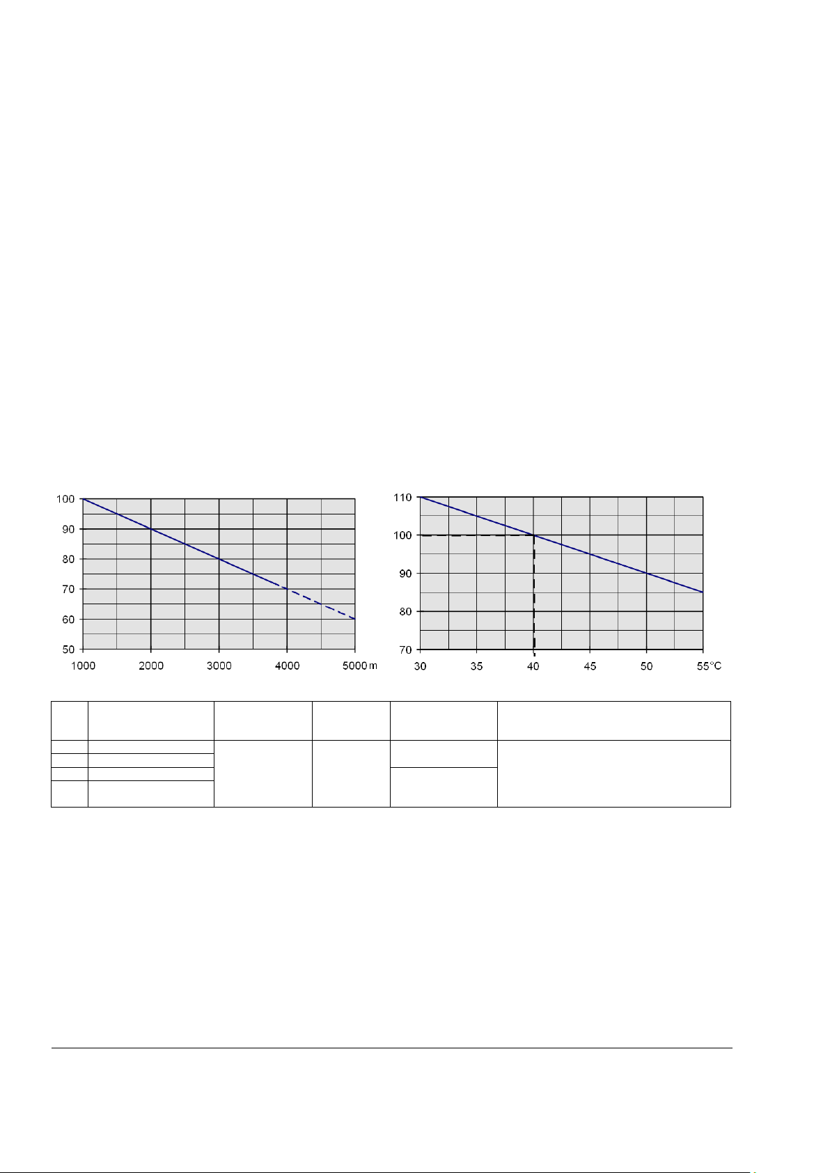
Site elevation
Paint finish
<1000 m above mean sea level:
100%, without current reduction
Converter modules:
Dark grey RAL 7012
>1000 m above mean sea level:
with current reduction, see figure
below
Effect of the site elevation above sea level on the converter’s load
capacity:
Effect of the ambient temperature on the converter module load
capacity:
Current reduction to (%)
Current reduction to (%) for converter modules
Size
Sound pressure level
LP (1 m distance)
Vibration
Shock
Transport in
original Package
Short circuit withstand rating
The DCS
capable of delivering not more than:
F1
55 dBA
1.5 mm, 2 - 9 Hz
0.5 g, 9
7 g / 22 ms
1.2 m
65 kA rms symmetrical ampere at a maximum
of 600 V
F2
55 dBA
F3
60 dBA
1.0 m
F4
66 - 70 dBA,
depending on fan
Environmental Conditi ons
The technical data contain the technical specifications of the drive, e.g. the ratings, sizes and technical
requirements, provisions for fulfilling the requirements for CE and other markings and warranty policy.
be taken for voltage deviation in
- 200 Hz
550 is suitable for use in a circuit
AC
The DCS550
3ADW000379R0501 DCS550 Manual e e

Regulatory Compliance
European Union Directive
Manufacturer's Assurance
Harmonized Standards
Machinery Directive
98/37/EEC
93/68/EEC
Declaration of Incorporation
EN 60204-1
[IEC 60204-1]
Low Voltage Directive
73/23/EEC
93/68/EEC
Declaration of Conformity
EN 61800-1
[IEC 61800
EN 60204
[IEC 60204-1]
EMC Directive
89/336/EEC
93/68/EEC
Declaration of Conformity
(
selection, cabling and EMC filters or dedic
transformer are followed.)
EN 61800-3
[IEC 61800-3]
in accordance with
3ADW000032
Rated supply voltage
Standards
up to 525 V
−
See UL Listing www.ul.com / certificate no. E196914
−
− or on request
The drive’s basic type code: DCS550-AAX-YYYY-ZZ-BB
Product family:
DCS550
Type:
AA
= S0
Standard converter modules IP00
Bridge type:
X
= 1
Single bridge (2-Q)
= 2
2 anti parallel bridges (4-Q)
Module type:
YYYY
=
Rated DC current
Rated AC voltage:
ZZ
= 05
230 VAC - 525 VAC
Fan voltage:
BB
= 00
Standard
F1:
F2, F3:
F4:
Additional informat ion:
CC
The converter modules are designed for use in industrial environments. In EEA countries, the components
fulfill the requirements of the EU directives, see table below.
13
If all installation instructions concerning cable
ated
North American Standards
In North America, the system components fulfill the requirements of the table below.
AC
Approval: cULus The spacings in the modules were evaluated to table 36.1 of
UL 508 C. Spacings also comply with table 6 and table 40 of C22.2 No. 14-05.
Type code
The type code contains information on the specifications and configuration of the drive.
Description see below:
-1]
-1
no fan 20 A / 25 A
24 VDC internal 45 A - 100 A
115 VAC / 230 VAC; single phase
230 VAC; single phase
The DCS550
3ADW000379R0501 DCS550 Manual e e

14
Mains voltage
Maximum DC voltage
Ideal DC voltage
DC voltage class
UVN [VAC]
U
d max 2-Q
[VDC]
U
d max 4-Q
[VDC]
Ud0 [VDC]
230
265
240
310
05
380
440
395
510
05
400
465
415
540
05
415
480
430
560
05
440
510
455
590
05
460
530
480
620
05
480
555
500
640
05
500
580
520
670
05
525
610
545
700
05
+
∗∗≤
%100
%100
35.1
TOL
UU
VNF
Size
IA, 2-Q
P
[kW] ①
IA, 4-Q
P
[kW] ①
Mains
IF
P
Air flow
Auxiliary
F1
20
12
25
13
230 - 525
1 - 12
0.11
no fan
115 VAC,
45
26
50
26
0.17
150
65
38
75
39
0.22
150
90
52
100
52
0.28
150
F2
135
79
150
78
1 - 18
0.38
300
180
104
200
104
0.56
300
225
131
250
131
0.73
300
270
157
300
157
0.88
300
F3
315
183
350
182
2 - 25
0.91
300
405
235
450
234
1.12
300
470
280
520
276
1.32
500
F4
610
354
680
354
2 - 35
1.76
950
740
429
820
426
2.14
950
900 ②
522
1000 ③
520
2.68
1900
Voltage and current ratings
The maximum available armature voltages have been calculated using the following assumptions:
− U
− Voltage tolerance ±10 %,
− Internal voltage drop approximately 1 %
If a deviation or a voltage drop has to be taken into account in compliance with IEC and VDE standards, the
output voltage and / or the output current must be reduced.
The maximum available field voltage can be calculated using following formula:
= rated mains voltage, 3-phase,
VN
, with:
U
= field voltage,
F
= mains voltage and
U
VN
TOL = tolerance of the mains voltage in %.
[A]
out
[A]
① Ratings for 500 VAC -10 %
② 900 A
③ 1000 A
for 35°C and 850 ADC for 40°C ambient temperature
DC
for 35°C and 950 ADC for 40°C ambient temperature
DC
out
[VAC]
-15 % / +10 %
[A]
loss
[kW]
[m3/h]
voltage
230 VAC,
230 V
DC
-15 % / +10 %
The DCS550
3ADW000379R0501 DCS550 Manual e e
Current ratings - IEC non regenerative
Converter type (2
Internal field
current
continuous
15 min
60 s
15 min
120 s
15 min
10 s
525 V
[A]
[A]
[A]
[A]
DCS550-S01-0020-05
20
16
24
16
24
15
30
DCS550-S01-0045-05
45
36
54
35
52
31
62
DCS550-S01-0065-05
65
54
81
52
78
49
98
DCS550-S01-0090-05
90
76
114
74
111
73
146
DCS550-S01-0135-05
135
105
157
100
150
93
186
F2
1 - 18 A
DCS550-S01-0180-05
180
130
195
125
187
110
220
DCS550-S01-0225-05
225
170
255
165
247
148
296
DCS550-S01-0270-05
270
200
300
195
292
180
360
DCS550-S01-0315-05
315
240
360
235
352
215
430
F3
2 - 25 A
DCS550-S01-0405-05
405
310
465
300
450
270
540
DCS550-S01-0470-05
470
350
525
340
510
310
620
DCS550-S01-0610-05
610
455
682
435
652
425
850
F4
2 - 35 A
DCS550-S01-0740-05
740
570
855
540
810
525
1050
DCS550-S01-0900-05
900
680
1020
650
975
615
1230
Converter type (4
Internal field
current
continuous
100 %
15 min
150 %
60 s
100 %
15 min
150 %
120 s
100 %
15 min
200 %
10 s
525 V
[A]
[A]
[A]
[A]
DCS550-S02-0025-05
25
22
33
21
31
20
40
F1
1 -12 A
DCS550-S02-0050-05
50
38
57
37
55
33
66
DCS550-S02-0075-05
75
60
90
59
88
54
108
DCS550-S02-0100-05
100
85
127
83
124
80
160
DCS550-S02-0150-05
150
114
171
110
165
100
200
F2
1 - 18 A
DCS550-S02-0200-05
200
145
217
140
210
115
230
DCS550-S02-0250-05
250
185
277
180
270
165
330
DCS550-S02-0300-05
300
225
337
220
330
200
400
DCS550-S02-0350-05
350
275
412
265
397
245
490
F3
2 - 25 A
DCS550-S02-0450-05
450
350
525
340
510
310
620
DCS550-S02-0520-05
520
400
600
380
570
350
700
DCS550-S02-0680-05
680
525
787
510
765
475
950
F4
2 - 35 A
DCS550-S02-0820-05
820
630
945
610
915
565
1130
DCS550-S02-1000-05
1000
750
1125
725
1087
660
1320
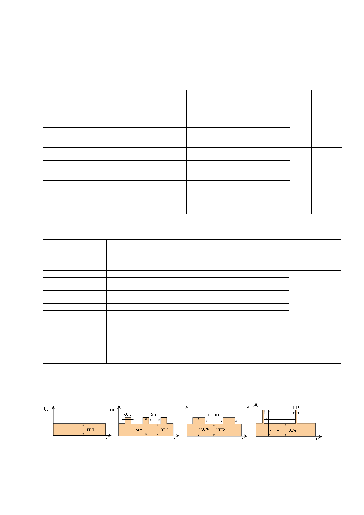
See the current ratings including several standard duty cycles for the DCS550 with 50 Hz and 60 Hz supplies
below. The current ratings are based on an ambient temperature of maximum 40°C and an elevation of
maximum 1000 m above mean sea level:
-Q) I
I
DC I
100 %
I
DC II
150 %
100 %
I
DC III
150 %
100 %
Size
DC IV
200 %
F1 1 - 12 A
Note:
AC current I
= 0.82*IDC
AC
Current ratings - IEC regenerative
15
-Q) I
I
DC I
I
DC II
Note:
AC current I
= 0.82*IDC
AC
Sizing and standard duty cycles:
The ratings apply at ambient temperature of 40 °C (104 °F).
I
DC III
Size
DC IV
The DCS550
3ADW000379R0501 DCS550 Manual e e
16
Size
h * w * d [mm]
h * w * d [inch]
weight [kg]
weight [lbs]
F1
370*270*208
14.57*10.63*8.19
11
24
F2
370*270*264
14.57*10.63*10.39
16
35
F3
459*270*310
18.07*10.63*12.21
25
55
F4
644*270*345
25.35*10.63*13.58
38
84
Size F1:
Size F2:
Size F3:
Size F4:
DCS550-S01-0020
DCS550
DCS550
DCS550
DCS550
DCS550
DCS550
DCS550-S02-0100
DCS550-S01-0135
DCS550
DCS550
DCS550
DCS550
DCS550
DCS550
DCS550-S02-0300
DCS550-S01-0315
DCS550-S01-0610
DCS550
DCS550
DCS550
DCS550
DCS550
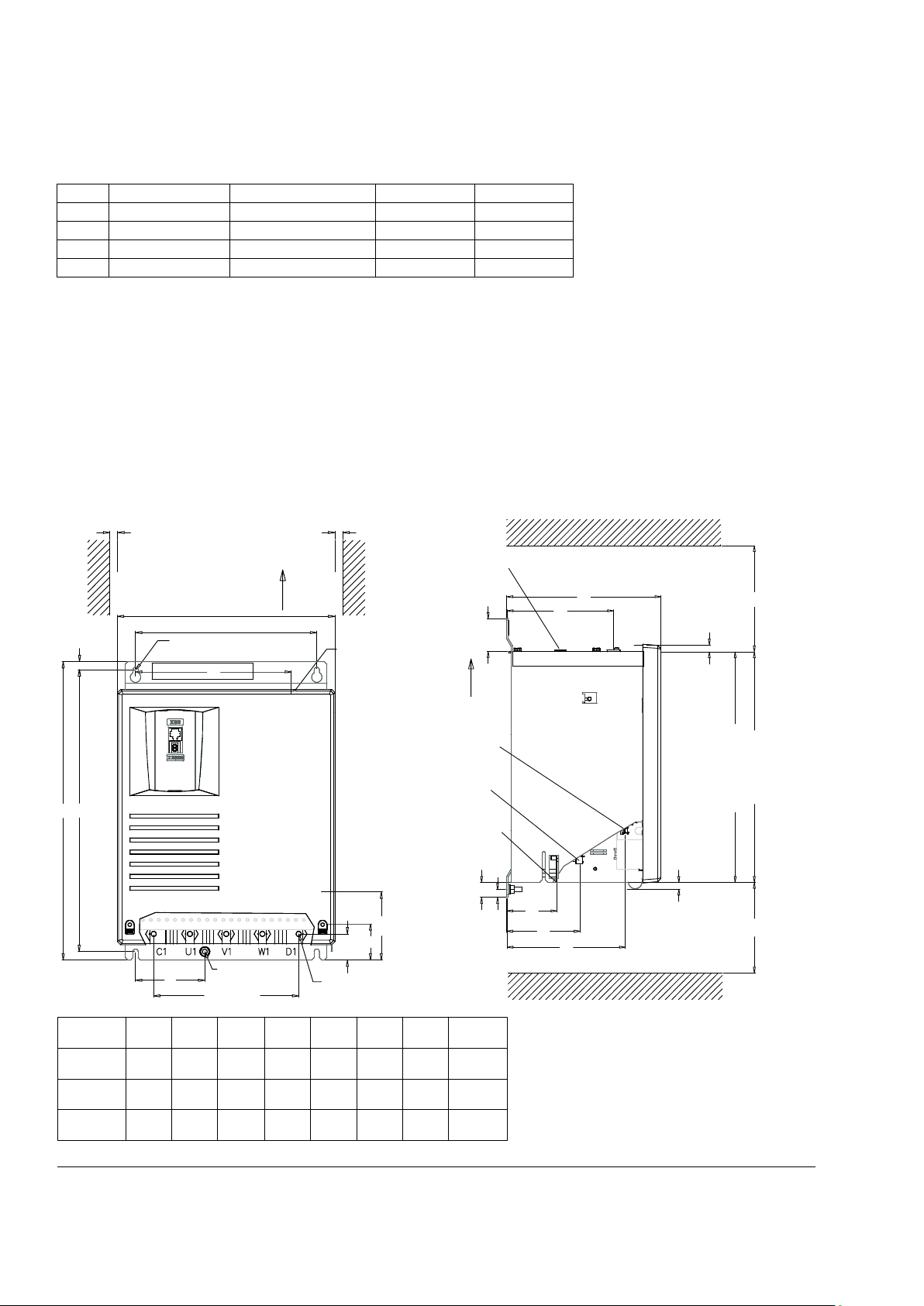
270
225
193.5
S
S
4 x 45 = 180
32.5
45
10
A
B
84.6
86
DCS550
S = 5 mm for size F1
S = 10 mm for size F2 - F3
Direction of air flow
Fan terminal
for Screw
Screw M6
Earthing
point H
D
E
F
G
C
43.5
20
10.5
9
8.7
T1
T1
Field terminal
Signal te
r
minals
P
o
w
er supply
ter
minals
Pow
er connection
MG_550_001_F1-F3_a-ai
Mounting Direction
Mini
mum top clear
ance
T1 = 150 mm
for si
ze F1
T1 = 250 mm
f
or siz
e F2 / F3
Minim
um bottom clear
ance
T2 = 100 mm
f
or siz
e F1
T2 = 150 mm
for si
ze F2 / F3
310
f
or si
z
e F1 / F2
400
f
or si
z
e F3
A
F1
F2
F3
370
370
459
350
350
437.5
165
-
242
208
264
310
79
121.5
147.5
110
163.5
205
157
212
255
M6
M10
M10
B C D E F G
H
Size
Dimensions and weights
See the dimensional drawings of the DCS550 below. The dimensions are in millimeters.
-S01-0045
-S01-0065
-S01-0090
-S02-0025
-S02-0050
-S02-0075
Size F1-F3:
-S01-0180
-S01-0225
-S01-0270
-S02-0150
-S02-0200
-S02-0250
DCS550-S01-0405
DCS550-S01-0470
DCS550-S02-0350
DCS550-S02-0450
DCS550-S02-0520
-S01-0740
-S01-0900
-S02-0680
-S02-0820
-S02-1000
The DCS550
3ADW000379R0501 DCS550 Manual e e
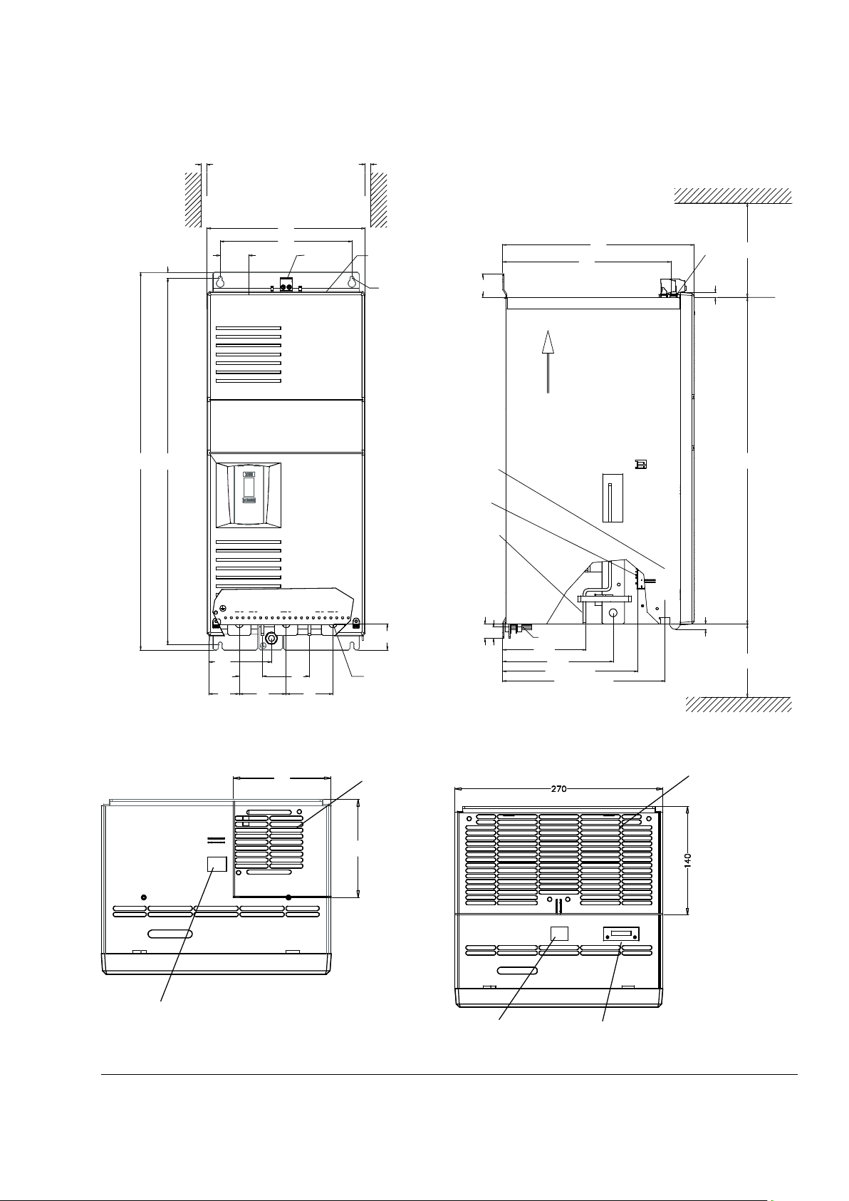
Size F4:
Top view, F1 45 A – 100 A
Top view, F2 135 A – 300 A
S
225
625
644
48.5
10
270
S
S = 10 mm
U1 V1 W1
D1
80
80
45
80
40
52
107
C1
DCS550
Power terminals: 40 x 5 mm
Fan terminal
for M6
Field terminals
for M12
298
345
42
8.7
250
577
150
9
25
20
147.5
195.5
240 (PIN-F01)
287.5 (CON-F01)
MG_550_002_F4_a.ai
Fan terminal
Minimum top clearanceMinimum bottom clearance
Direction of air flow
Earthing
point H
Earthing M12
Signal terminals
Power supply
terminals
Power connection
X10
115
115
MG_550_003_fans_a.ai
recommended
air exhaust duct
115 x 115 mm
Field terminals
X10 X52
MG_550_003_fans_a.ai
recommended
air exhaust duct
140 x 270 mm
Field terminals Fan terminal
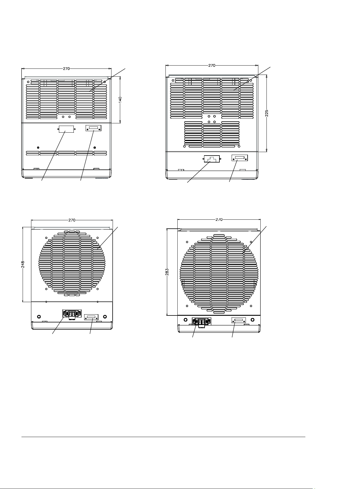
17
Field-, fan terminals and cooling air duct sizes
The DCS550
3ADW000379R0501 DCS550 Manual e e
18
Top view, F3 315 A – 450 A
Top view, F3 470 A – 520 A
Top view, F4 610 A – 820 A
Top view, F4 900 A – 1000 A
X10 X52
recommended
air exhaust duct
140 x 270 mm
Field terminals F
an terminal
X10 X52
MG_550_003_fans_a.ai
recommended
air exhaust duct
225 x 270 mm
Field terminals Fan terminal
X10 X52
recommended
air exhaust duct
248 x 270 mm
Field terminals Fan terminal
X10 X52
MG_550_003_fans_a.ai
recommended
air exhaust duct
283 x 270 mm
Field terminals Fan terminal
The DCS550
3ADW000379R0501 DCS550 Manual e e
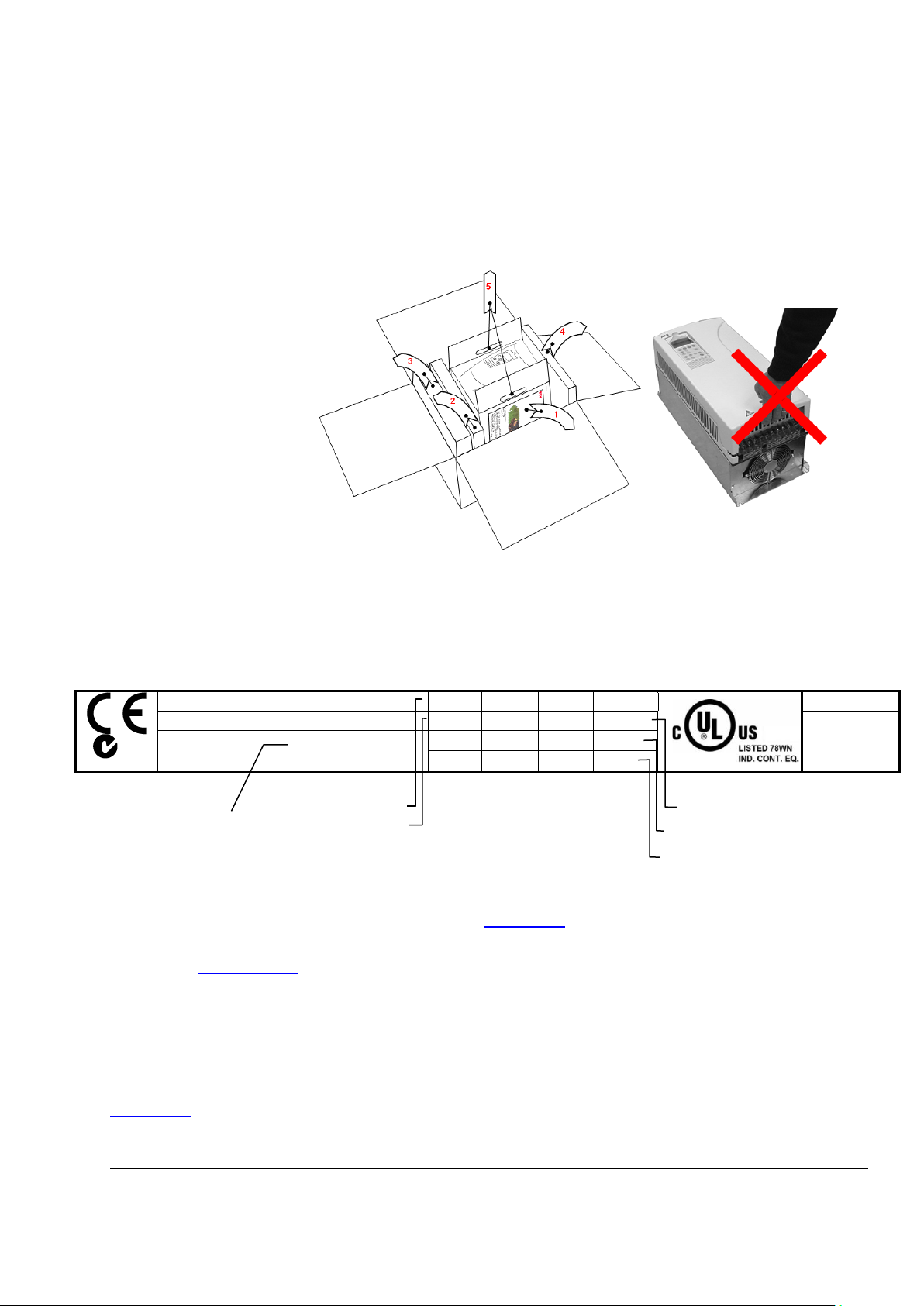
Mechanical installation
−
−
−
Attention:
Do
cover!
ABB Automation Products GmbH
U
1
U2
610 V
Made in Germany
Type: DCS550-S02-0075-05-00-00
I1
62 A
I2 75 A
Ser No: 0025421A10524264
f1
50/60 Hz
If
18 A
SCCR
65 kA
Fan
----
Rated input voltage
Rated output current
Chapter overview
This chapter describes the mechanical installation of the DCS550.
Unpacking the unit
Open the box,
take out shock dampers,
separate manual and
accessories.
not lift the drive by the
19
Delivery check
Check that there are no signs of damage. Before attempting installation and operation, check the information
on the nameplate of the converter module to verify that the unit is of the correct type. The label includes an
IEC rating, cULus, C-tick (N713) and CE markings, a type code and a serial number, which allow individual
identification of each unit. The remaining digits complete the serial number so that there are no two units with
the same serial number. See an example nameplate below.
3 ∼ 525 V
N713
Production year
2010 and week 52
Rated input current
Rated internal field exciter
current
Rated fan voltage
Before installation
Install the drive in an upright position with the cooling section facing a wall. Check the installation site
according to the requirements below. Refer to chapter Dimensions
Requirements for the installation site
See chapter Technic al dat a for the allowed operation conditions of the drive.
Wall
The wall should be as close to vertical as possible, of non-flammable material and strong enough to carry the
weight of the unit. Check that there is nothing on the wall to inhibit the installation.
Floor
The floor or material below the installation must be non-flammable.
Free space around the unit
Around the unit free space is required to enable cooling airflow, service and maintenance see chapter
Dimensions
.
for frame details.
Mechanical installation
3ADW000379R0501 DCS550 Manual e e
20
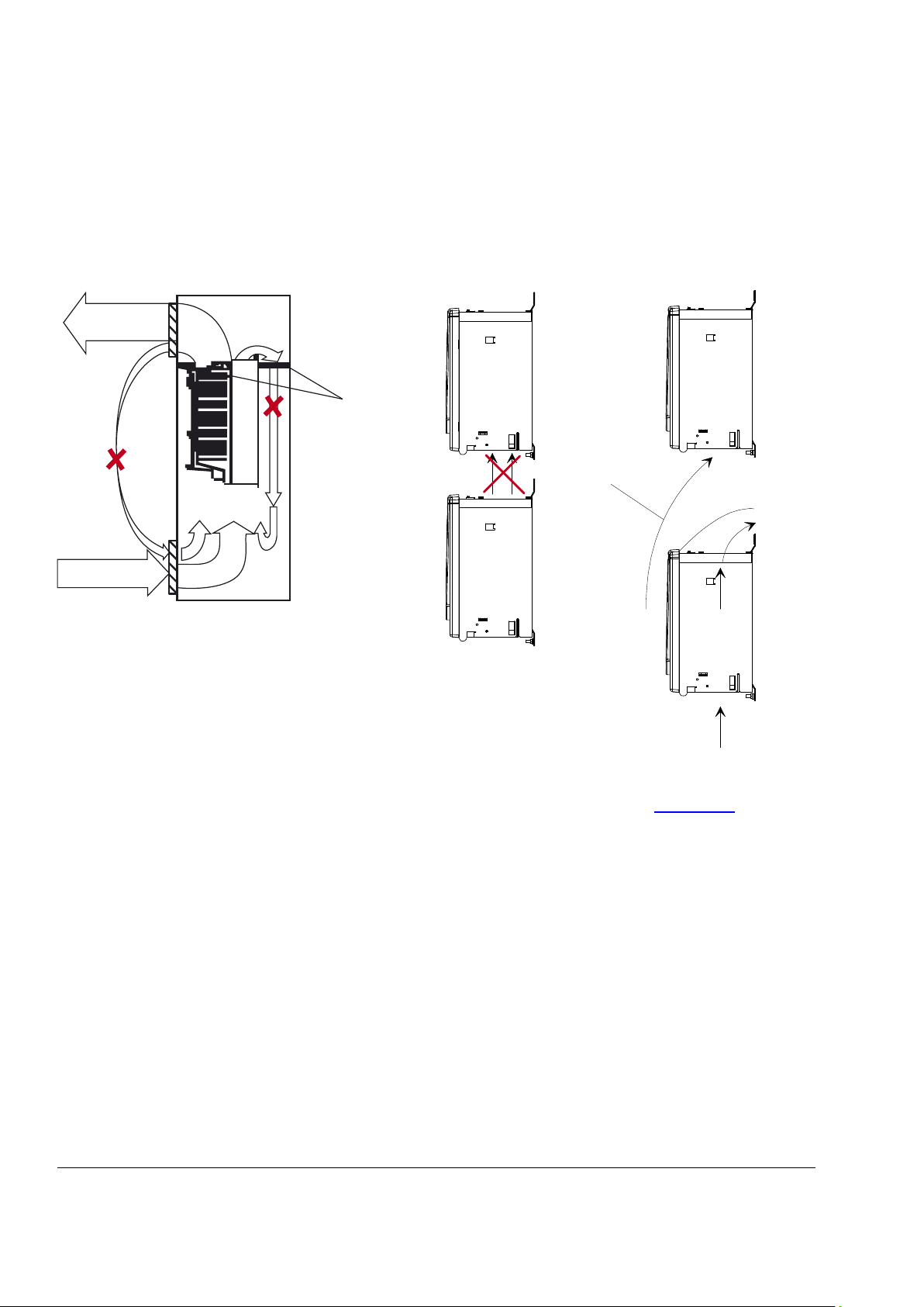
Preventing cooling air recirculation
Unit above another
Prevent air recirculation inside and outside the cabinet
Lead the exhaust cooling air away from the unit
above. Distances see chapter Dimensions.
BG_800_004_luft_a.ai
Hot area
Cool area
Main air flow in
Air ba
f
fle plates
Main air flow out
max.+40°C
BG_800_003_luft_a.ai
Air baffle plate
Airflow
Cabinet installation
The required distance between parallel units is five millimeters (0.2 in.) in installations without front cover. The
cooling air entering the unit must not exceed +40°C (+104°F).
Mechanical installation
3ADW000379R0501 DCS550 Manual e e

Planning the electrical installation
Chapter overview
This chapter contains the instructions that must be followed when selecting the motor, cables, protections,
cable routing and way of operation for the drive system. Always follow local regulations. This chapter applies
to all DCS550 converter modules.
Attention:
If the recommendations given by ABB are not followed, the drive may experience problems that the warranty
does not cover. See also Technical Guide.
21
Electrical installation
3ADW000379R0501 DCS550 Manual e e
22
X96:
DO8
1 2 X52: 1 2 3
U1 W1V1 PE
K1
K20
K21K20 K1
X96:1
X96:2
L1 L2 L3
525V, 50/ 60Hz
F1
M
1~
K21
C 1 D 1
AITAC AI1
AI2 AI3
AI4
+10V -10V AO1 AO2 I
ACT
DI1 DI2 DI3 DI4 DI5 DI6 DI7 DI8 +24V DO1 D O2 DO3 DO4
_ _ _ _
_
+ + + +
+
Encoder
T
E
M
GND
GNDGNDGNDGND
NCNCNC
X1: 1 2 3 4 5 6 7 8 9 10 X2: 1 2 3 4 5 6 7 8 9 10 X4: 1 2 3 4 5 6 7 8 9 10
X5:
1 2 3 4 5 6 7 8 1...10
X3:
+
_
+
_
K1
K20
K21
F5
1
2
F8
1
2
F7
1
2
K1
1 3 5
2 4 6
L1
F+
F-
X10:
L1 N
2
1
4
3
6
5
F6
I > I > I >
13
14
U
V
W
M
3~
SF_550_004_ans_a.ai
*
2
1
6
5
X99: 1 2
DCS550
(SDCS-BAB-F)
(SDCS-PIN-F)
Control board (SDCS-CON-F)
Power supply
Converter
module
ON
OFF STOP
START
OnBoard f
ieldexciter
depending on the unit type
another configuration is possible
the polarities are shown for motor operation
if there are intermediate terminals
Aux. supply
* set by
[50.12],
[50.13]
Legend
fuse
reactor
see 6.03
bit 7
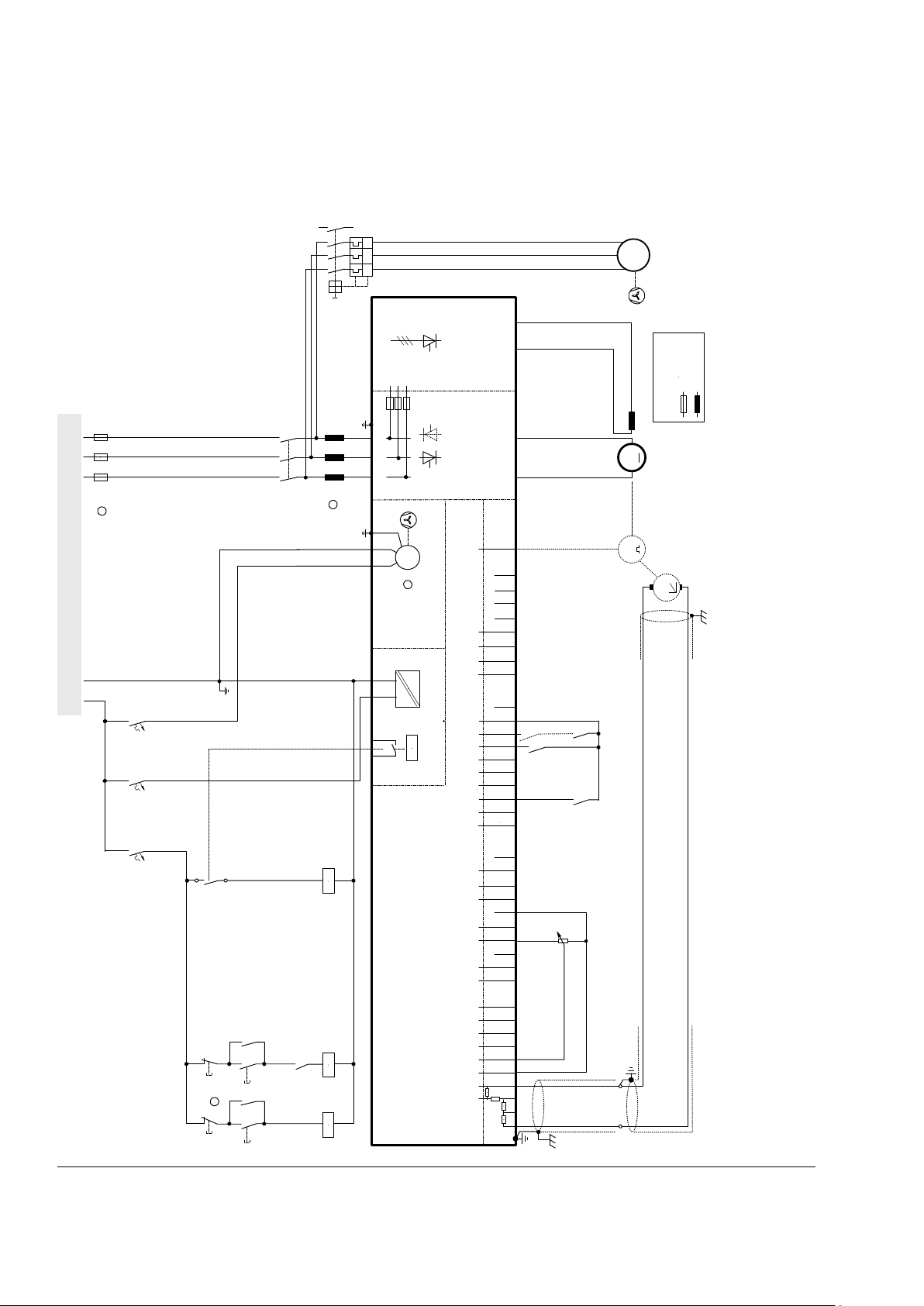
Drive connection and wiring example
The drive configuration with a reduced set of components gives the same control performance, but a lower
degree of monitoring functions.
Electrical installation
3ADW000379R0501 DCS550 Manual e e
X96:
DO8
1 2
X52:
1
2 3
U1
W1V1
PE
K1
F6
K20
K21K20 K1
X96:1
X96:2
L1 L2 L3
F1
M
1~
F2
3
4
1
2
T2
690V
660V
600V
575V
525V
500V
450V
415V
400V
380V
115V
230V
K15
K15
S1
1
2
K6 K8
K10
K21
C 1
D 1
AITAC AI1
AI2 AI3
AI4
+10V
-10V AO1 AO2 I
A
CT
DI1 D I2 DI3
DI4 DI5 DI6
DI7 D I8
+24V
DO1 DO2 DO3 DO4
_
_ _ _
_
+ + +
+
+
Encoder
T
E
M
GND
GNDGND
GND
GND
NC NC NC
X1: 1 2 3 4
5 6 7 8
9 10
X2
: 1
2 3
4 5
6 7 8 9 10 X4:
1 2 3 4
5 6
7
8 9
10
X5:
1 2 3 4 5 6
7 8 1...10
X3
:
+
_
+
_
K1
K20
K21
K6
K8
1
2
S1
K10
2
4 6
1
3 5
K6
F5
1
2
F8
1
2
F7
1
2
2
1
4
3
6
5
F6
I > I > I >
13
14
U
V
W
M
3~
K1
1 3 5
2 4 6
L1
1
2
3
4
K8
13
14
X10
: F+
F-
L1 L2 L1 L2 L3
SF_550_003_ans_a.ai
DCS550
*
(SDCS-PIN-F)
525V, 50/ 60Hz
EMC Filter
E1
see 6.03
bit 7
(SDCS-BAB-F)
see 6.03
bit 0
X99: 1 2
Control board (SDCS-CON-F)
Po
wer supply
Converter
module
ON
OFF
STOP
ST
ART
EMER.
STOP
OnBoard fielde
xciter
depending on the unit type
another configu
r
ation is possible
the polar
ities are shown f
or motoring
if there are inte
rmediate te
rminals
* set by
[50.12],
[50.13]
Leg
end
fuse
reactor
Line reactor
Motor
f
an
fu
rther inf
ormation see chapter
Start,Stop and E-stop control
Aux supply Aux supply
3
4
5
6
5
2
1
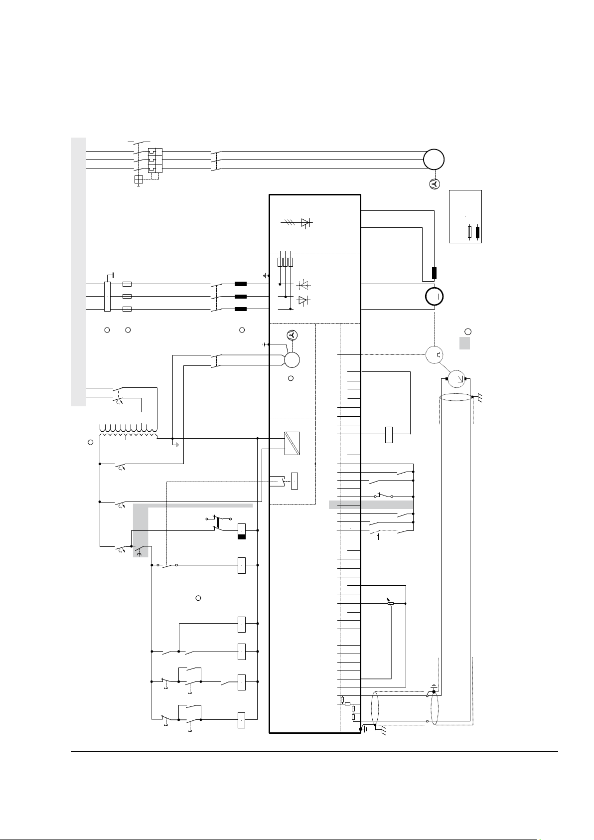
The drive configuration with a full set of components offers the highest degree of monitoring functions.
23
3ADW000379R0501 DCS550 Manual e e
Electrical installation
24
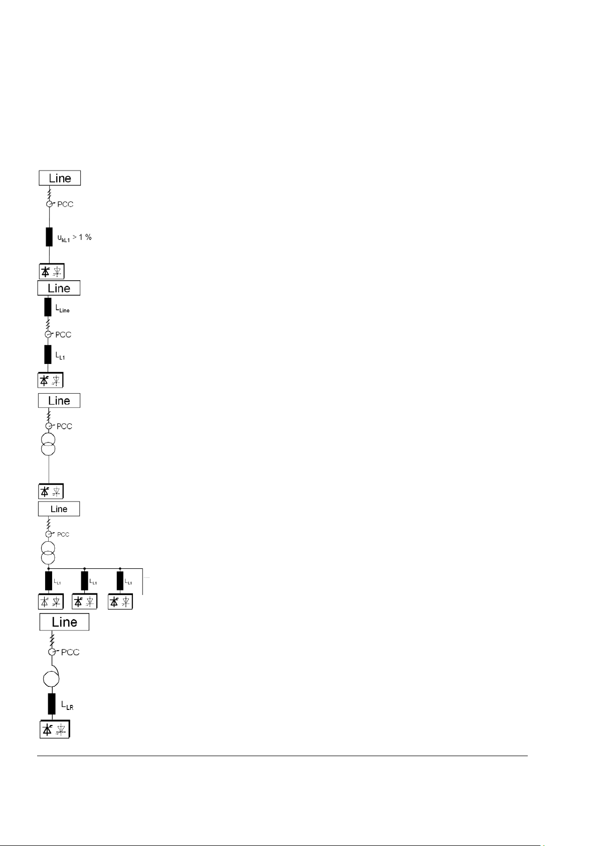
Configuration A
When using the power converter, a minimum of impedance is required to ensure proper
performance of the snubber circuit.
requiremen
should not exceed 10 % u
Configuration B
If special requirements have to be met at the PCC (standards like E
drives at the same line, etc), different criteria must be applied for selecting a line reactor. These
requirements are often defined as a voltage dip in percent of the nominal supply voltage. The
combined impedance of Z
ratio between the line impedance and the line reactor impedance determines the voltage dip at
the connecting point. In such
Example
Voltage dip = Z
Line
/ (Z
Line
+ ZL1) = 20 %. Detailed calculations see Technical Guide.
Configuration C
If an isolation transformer is used, it is possible to comply with certain connecting conditions per
Configuration B without using an additional line reactor. The condition described in Configuration
A will then likewise be satisfied, since the u
Configuration C1
When supplying
that each
Configuration D
In the case of high power converter
When using
because
Installation components
① Line reactors (L1)
When thyristor power converters operate, the line voltage is short-circuited during commutation from one
thyristor to the next. This operation causes voltage dips in the mains PCC (point of common coupling). For the
connection of a power converter system to the mains, one of the following configurations applies:
Use a line reactor to meet this minimum impedance
t. The value must therefore not drop below 1 % uk (relative impedance voltage). It
, due to considerable voltage drops at the converter outputs.
k
N 61 800-3, DC and AC
and ZL1 constitute the total series impedance of the installation. The
Line
cases, line chokes with an impedance around 4 % are often used.
calculation with ukLine = 1 % and ukL1 = 4 %:
is > 1 %.
k
2 or more converters by one transformer use conf iguration A or B. One can see
drive needs its own line reactor.
s, frequently a trans f ormer is used for voltage matching.
an autotransformer for this purpose, additionally install a commutating reactor,
the uk of commonly used autotransformers is too small.
Electrical installation
3ADW000379R0501 DCS550 Manual e e
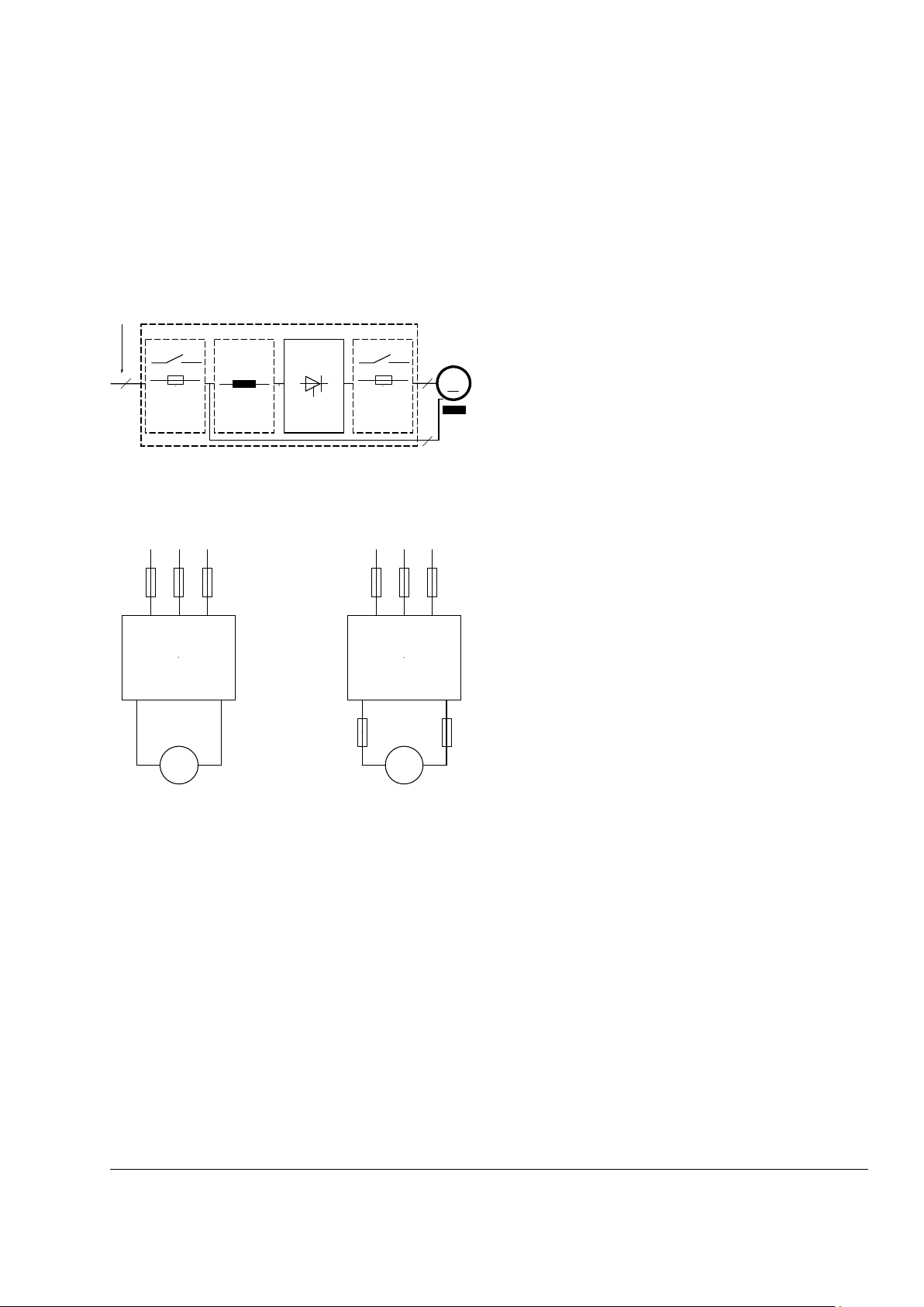
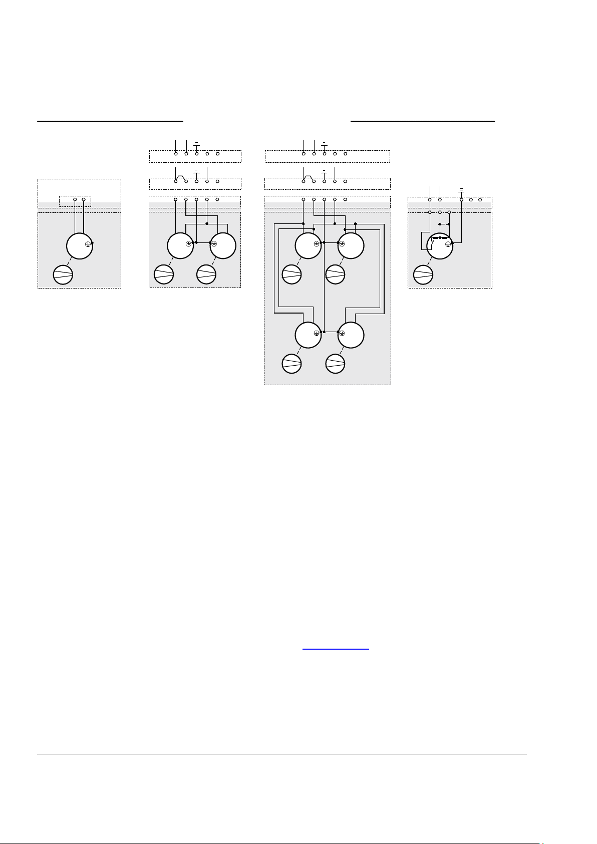
② Semiconductor fuses (F1)
The figure shows the arrangement of the switch-off
elements in the armature circuit. Further information
available
Never use standard fusing instead of semi-conductor
fusing in order to save money on the installation. In the
event of a
saved can cause the semiconductors or other devices to
explode and cause fires. Adequate pro
short circuit and earth fault, as depicted in the EN50178
standard, is possible only with appropriate
semiconductor fuses.
Use
protect the motor in case of a fault during regeneration.
DC fuses must be rated for the same current and voltage
as AC fuses, thus follows
M
.
.
.
.
.
.
3
2
2
SF_550_005_geräteschutz_a.ai
AC supply: public mains / plant's mains
Cabinet
M M
SF_800_009_fuses_a.ai
DCS converter
2-Q non-regen.
Semiconductor
fuses
Semiconductor
fuses
Semiconductor
fuses
4-Q resp.
2-Q regenerative
DCS converter
Aspects of fusing for the armature circuit of DC drives
Unit configuration
Protection elements such as fuses or overcurrent trip circuits are required in all cases to protect against
further damage. In some configurations, this will entail the following questions:
1. Where to place which protective element?
2. In the event of what faults will the element in question provide protection against damage?
in the Technical G uide .
Conclusion
25
is
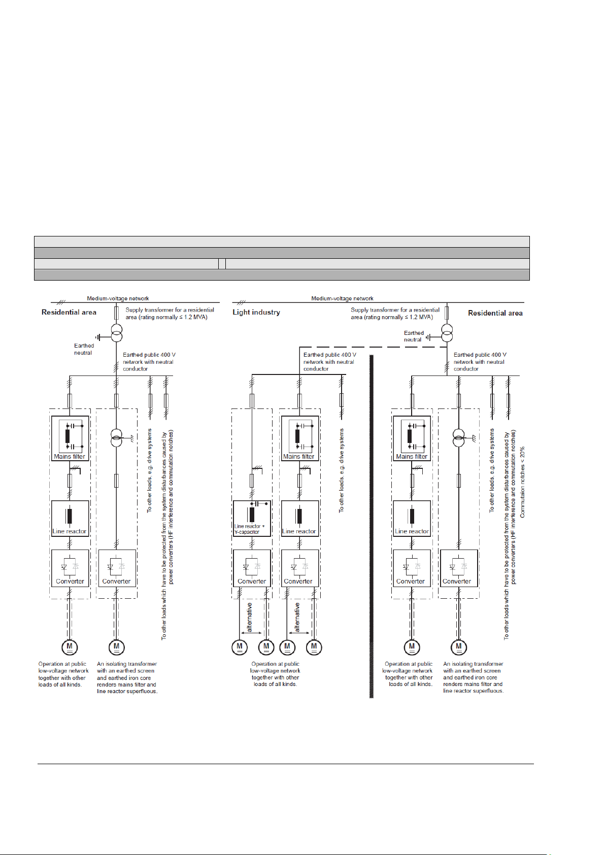
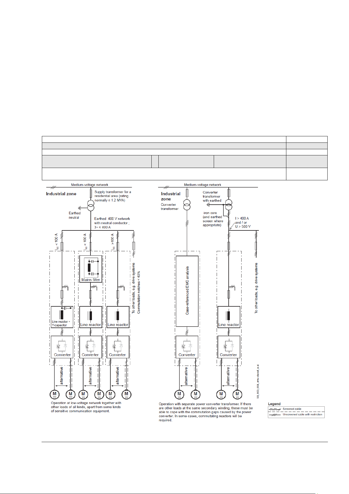
③ EMC filters (E1)
Filter in a grounded line (earthed TN or TT network)
The filters are suitable for grounded lines only, for example in public European 400 VAC lines. According to EN
61800-3 filters are not needed in insulated industrial networks with own supply transformers. Furthermore,
they could cause safety risks in such floating lines (IT networks). According to EN 61800-3 filters are not
needed in industrial zone (Second Environment) for DCS550 drives above 100 A
currents below 100 A
Three-phase filters
EMC filters are necessary to fulfill the standard for emitted interference if a converter shall be run at a public
low voltage line, in Europe for example with 400 V
offers suitable three-phase filters for 400 V
filters are available. Optimize the filters for the real motor currents:
Filter
= 0.8 * i
Mot max
− i
Lines with 500 V
sensitive electronics. Therefore, converters do not need EMC filters if they shall run with 500 V
, the filter requirement is identical to Light Industry (First Environment).
DC
; the factor 0.8 respects the current ripple.
and higher are not public. They are local networks inside factories, and they do not supply
AC
fault condition, the small amount of money
tection against
DC fuses (2 of them) for all regenerative drives to
DC fuses = AC fuses.
rated current. For rated
DC
. Such lines have a grounded neutral conductor. ABB
AC
. For 440 VAC public low voltage lines outside Europe 500 VAC
AC
and more.
AC
Electrical installation
3ADW000379R0501 DCS550 Manual e e
26
The paragraphs below describe selection of the
−
The EMC Guideline expects EMC to be taken into
First environment (residential area with light industry) with PDS category C2
Not applied, since category C1 (general distribution sal es c hanne l) ex cluded
Not applicable satisfied
satisfied
EMC filters
Further information
is available in the
Technical Guide.
electrical components in conformity with the
EMC Guideline. The aim of the EMC Guideline
is, as the name implies, to achieve
electromagnetic compatibility with other
products and systems. The guideline ensures
that the emissions from the product concerned
are so low that they do not impair another
product's interference immun it y .
In the context of the EMC Guideline, two
aspects must be borne in mind:
− the product's interference immunity and
the product's actua l emissions.
account when developing a product; however,
EMC cannot be designed in, it can only be
quantitatively measured.
Notes on EMC conformity:
The conformity procedure is the responsibility of
both the power converter' s sup plier and the
manufacturer of the machine or system
concerned, in proportion to their share in
expanding the electrical equipment involved.
Electrical installation
3ADW000379R0501 DCS550 Manual e e
For compliance with the protection
objectives of the German EMC Act
(EMVG) in systems and machines, the
following EMC standards must be satisfied:
Product Standard EN 61800
EMC
(
immunity and emissions in residential
areas, enterprise zones with light industry
and in industrial facilities. This standard
must be complied with in the EU for
sa
systems and machines!
For emitted interference, the following apply:
EN 61000
-6-3 Specialized basic standard for emissions in light industry
can be satisfied with special features (mains filters, screened
EN 61000
For interference immunity, the following apply:
EN 61000
EN 61000
* The old generic standards are given in brackets
Standards
Second environment (industry) with PDS categories C3, C4
EN 61800-3
Not applicable
EN 61000-6-3
satisfied
on customer's
request
satisfied
EN 61000-6-4
satisfied
EN 61000-6-2
EN 61000-6-1
Classification
The following overview
utilizes the terminology and
indicates the action required
in accordance with Product
Standard
EN 61800
For the DCS
limit values for emitted
interference are complied
with, provided the measure
indicated is carried
of category C2 (formerly
restricted distribution in first
environment) is intended to
be installed and
commissioned only by a
professional (person or
organization with necessary
skills in installing and/or
commissioning PDS
including their EMC asp
For power converters without
additional components, the
following warning applies:
This is a product of category
C2 under IEC 61800-3:2004.
In a domestic/residential
environment, this product
may cause radio interference
in which case supplementary
mitigation measures may be
required.
The field supply is not
depicted in this overview
diagram. For the field current
cables, the same rules apply
as for the armature
cables.
27
-3
standard for drive systems
PowerDriveSystem), interference
tisfying the EMC requirements for
power cables) in the lower rating range *(EN 50081-1).
-6-4 Specialized basic standard for emissions in industry *(EN
50081-2)
-6-1 Specialized basic standard for interference immunity in
residential areas *(EN 50082-1)
-6-2 Specialized basic standard for interference immunity in
industry. If this standard is satisfied, then the EN 61000-6-1
standard is automatically satisfied as well *(EN 50082-2).
-3
550 series, the
out. PDS
ects).
-circuit
Electrical installation
3ADW000379R0501 DCS550 Manual e e
28
The commands represented by K20 and K21
In case the E-stop push button is hit, the
setting, the drive must get the command to
the main contactor
is opened immediately, independent of the
K16
K15
K16
K15
DI4
K15
X6:9
SDCS-CON-4
S1
1
2
SF_CON4_001_E-stop_a.ai
E-Stop
electrical
disconnect
(coast)
Block
current
command
DZ_LIN_006_E-stop_b.ai
E-stop
Speed
Block current control
Main contactor K1
E-stop ramp Coast
Timer K15
Timer K16
④ Auxiliary transformer (T2) for converter electronics and fan
The converter module requires various auxiliary voltages, e.g. the module’s electronics and cooling fans
requires either a single-phase supply of 115 V
or 230 VAC. The auxiliary transformer (T2) is designed to
AC
supply the module’s electronics and cooling fans.
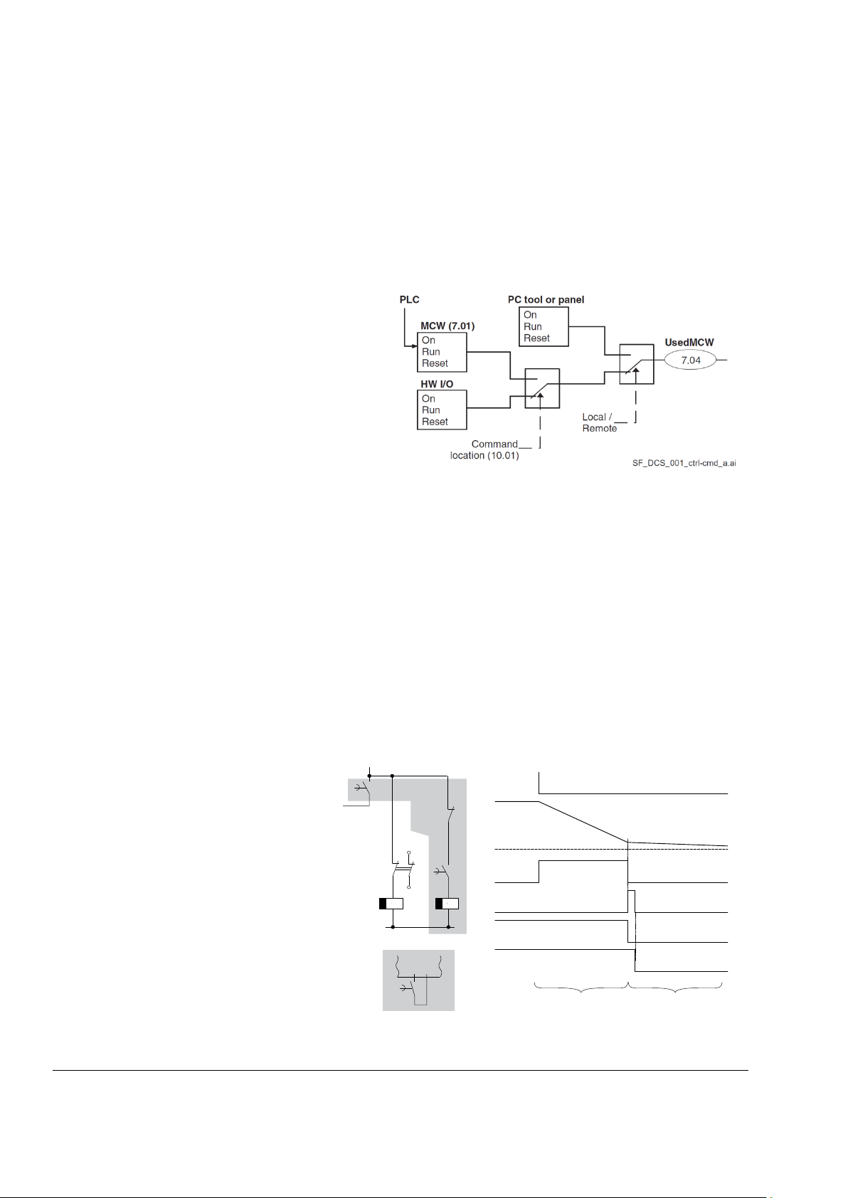
⑤ Start, Stop and E-stop control
The relay logic is splitted into three parts:
1. Generation of On / Off and Start / Stop commands:
(latching interface relay) can also be generated by
a PLC and transferred to the terminals of the
converter either by relays, using galv anic is ol ati on
or directly via 24 V signals. There is no need to
use hardwired signals. Transfer these commands
via serial communication. Even a mixed solution
can be realized by selecting different possibilities
for the one or the other signal (see parameter
group 11).
2. Generation of control and monitoring signals:
Control the main contactor K1 for the armature circuit by the dry contact of DO8 located on the
SDCS-PIN-F. The status of motor (K6) and converter (K8) fans can be monitored by means of MotFanAck
(10.06).
3. Off2 (Coast Stop) and Off3 (E-stop):
Beside On / Off and Start / Stop the drive is equipped with two additional stop functions Off2 (Coast Stop)
and Off3 (E-stop) according to Profibus standard. Off3 (E-stop) is scalable via E Stop Mo de (21.04) to
perform stop category 1. Connect this function to the E-stop push button without any time delay. In case of
E StopMode (21.04) = RampStop the K15 timer relay must be set longer than E StopRamp (22.04). For E
StopMode (21.04) = Coast the drive opens the main contactor immediately.
Off2 (Coast Stop) switches the DC current off as fast as possible and prepares the drive to open the main
contactor or drop the mains supply. For a normal DC motor load the time to force the DC current to zero is
below 20 ms. This function should be connected to all signals and safety functions opening the main
contactor. This function is important for 4-Q drives. Do not open main contactor during regenerative
current. The correct sequence is:
1. switch off regenerative current,
2. then open the main contactor.
information is transferred to the converter
via DI5. In case E StopMode (21.04) =
RampStop or TorqueLimit the converter
will decelerate the motor and then open
the main contactor. If the drive has not
finished the function within the K15 timer
switch off the current via K16. After the
K16 timer has elapsed,
drive’s status.
Electrical installation
3ADW000379R0501 DCS550 Manual e e

⑥ Cooling fans
Converter type
Size
Configuration
Fan type
DCS550-S01-0020, …,
DCS550-S02-0025
F1
-
No fan, convection cooled
DCS550-S01-0045, …,
DCS550-S02-0100
1
1 x 3110 KL-05W (internal 24 VDC)
DCS550-S01-0135, …,
DCS550-S02-0300
F2
2
2 x 4715 MS-12T (115 VAC / 230 VAC)
DCS550-S01-0315, …,
DCS550-S02-0450
F3
DCS550-S01-0470, …,
DCS550-S02-0520
3
2 x 4715 MS-12T (115 VAC / 230 VAC)
2 x 3115 FS-12T (115 V
/ 230 V
)
DCS550-S01-0610, …,
DCS550-S02-0820
F4
4
1 x W2E200 (230 VAC)
DCS550-S01-0900, …,
DCS550-S02-1000
1 x W2E250 (230 VAC)
Fan
3110 KL-05W
4715 MS-12T
3115 FS-12T
W2E200
W2E250
Rated voltage [VAC]
DC
115; 1~
115; 1~
230; 1~
230; 1~
Tolerance [%]
+15 / -50
± 10
± 10
+6 / -10
+6 / -10
Frequency [Hz]
-
50
60
50
60
50
60
50
60
Power consumption [W]
2.88
16
13
9.5
8.0
64
80
135
185
Current consumption [A]
0.12
0.2
0.17
0.075
0.060
0.29
0.35
0.59
0.82
Blocking current [A]
-
< 0.3
< 0.26
< 0.085
< 0.075
< 0.7
< 0.8
< 0.9
< 0.9
Air flow [m3/h] freely blowing
66
156
180
47.5
55
925
1030
1860
1975
Max. ambient temp. [°C]
< 70
< 60
< 70
< 70
< 60
Useful lifetime of grease
approximately
70,000 h / 25°
approximately
40,000 h / 60°
approximately
50,000 h / 20°
approximately 40,000 h / 60°
Protection
DC
Impedance
Internal temperature detector
①
②
permissible for the insulation class being involved.
Fan assignment for DCS550:
Fan data for DCS550:
24 V
29
①
Impedance ②
Internally connected
Increased losses due to increased current with a blocked rotor will not result in a winding temperature, higher than
Electrical installation
3ADW000379R0501 DCS550 Manual e e
30
1 2 3X52: 4 5
L
N
1 2 3
X52:
4 5
L
N
115V
AC
M
~
1 2 3
X52:
M
~
4 5
M55 M56
M
~
1 2 3
X52:
M
~
4 5
M55 M56
M
~
M
~
M57 M58
M55
M
~
1 2 3 4 5
X52:
L N
L
N
1 2 3
X52:
4 5
L
N
230V
AC
230V
AC
1 2 3X52: 4 5
L
N
115V
AC
J
M55
M
~
X19:
SDCS-PIN-F
F4F3F2, F3F1
SA_550_002_fan_a.ai
only 230 V
AC
Configuration 4Configuration 3Configuration 2Configuration 1
Terminals are located on top of the converter housing
Fan connection for DCS550:
Cabling
Thermal overload and short-circuit protection
The drive protects itself and the input and motor cables against thermal overload when the cables are
dimensioned according to the nominal current of the drive.
Power cables
Dimension the mains and motor cables according to local regulations. The cables must:
1. be able to carry the DCS550 load current,
2. be rated for at least 60°C (140°F),
3. fulfill short-circuit protection,
4. be rated according permissible touch voltage appearing under fault conditions (so that the fault point
voltage will not rise too high when an earth fault occurs) and
5. be screened according to safety regulations.
Mains cable (AC line cable) short-circuit protection
Always protect the input cable with fuses. Size the fuses according to local safety regulations, appropriate
input voltage and the rated current of the drive, see chapter Technical Data
High-speed semiconductor fuses provide short-circuit protection, but do not provide thermal overload
protection.
.
Electrical installation
3ADW000379R0501 DCS550 Manual e e
 Loading...