

Page 1
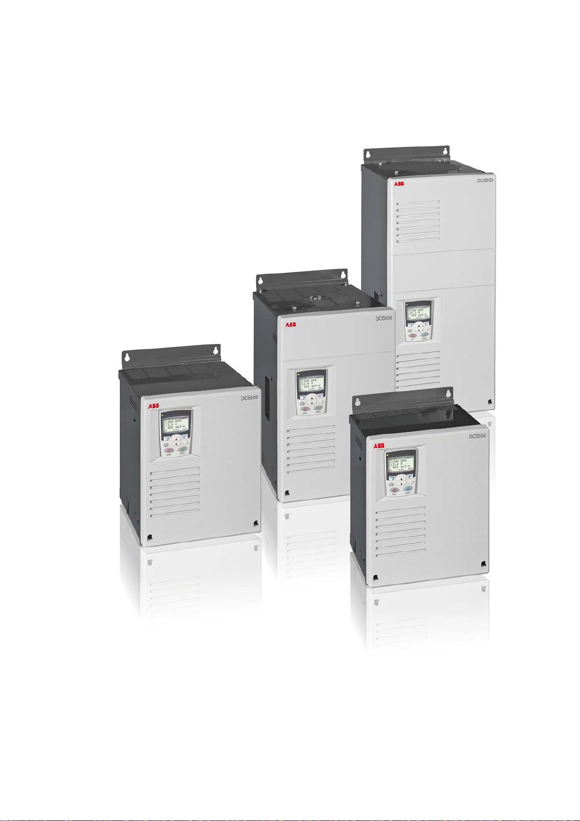
DCS550
Manual
DCS550 Drives (20 A to 1000 A)
ABB
Page 2

DCS550 Manuals
Public. number E D I ES F CN RU
Quick Guide
DCS550 Tools & Documentation CD
DCS550 Modules
DCS550 Flyer 3ADW000374 x x
DCS550 Technical Catalogue 3ADW000378 p
DCS550 Manual 3ADW000379 x
DCS550 Service Manual 3ADW000399 p
Installation according to EMC 3ADW000032 x
Technical Guide 3ADW000163 x
Extension Modules
RAIO-01 Analogue IO Extension 3AFE64484567 x
RDIO-01 Digital IO Extension 3AFE64485733 x
Serial Communication
RPBA-01 PROFIBUS 3AFE64504215 x
RCAN-01 CANopen 3AFE64504231 x
RCNA-01 ControlNet 3AFE64506005 x
RDNA-01 DeviceNet 3AFE64504223 x
RMBA-01 MODBUS 3AFE64498851 x
RETA-01 Ethernet 3AFE64539736 x
x -> existing p -> planned
Status 05.2011
DCS550 Drive Manuals-List_d.doc
3ADW000395 x x x x x
3ADW000377 x
Language
Page 3
Safety instructions
Chapter overview
This chapter contains the safety instructions you must follow when installing, operating and servicing the drive.
If ignored, physical injury or death may follow, or damage may occur to the drive, the motor or driven
equipment. Read the safety instructions before you work on the unit.
To which products this chapter applies
The information is valid for the whole range of the product DCS550.
Usage of warnings and notes
There are two types of safety instructions throughout this manual: warnings and notes. Warnings caution you
about conditions, which can result in serious injury or death and/or damage to the equipment, and advice on
how to avoid the danger. Notes draw attention to a particular condition or fact, or give information on a
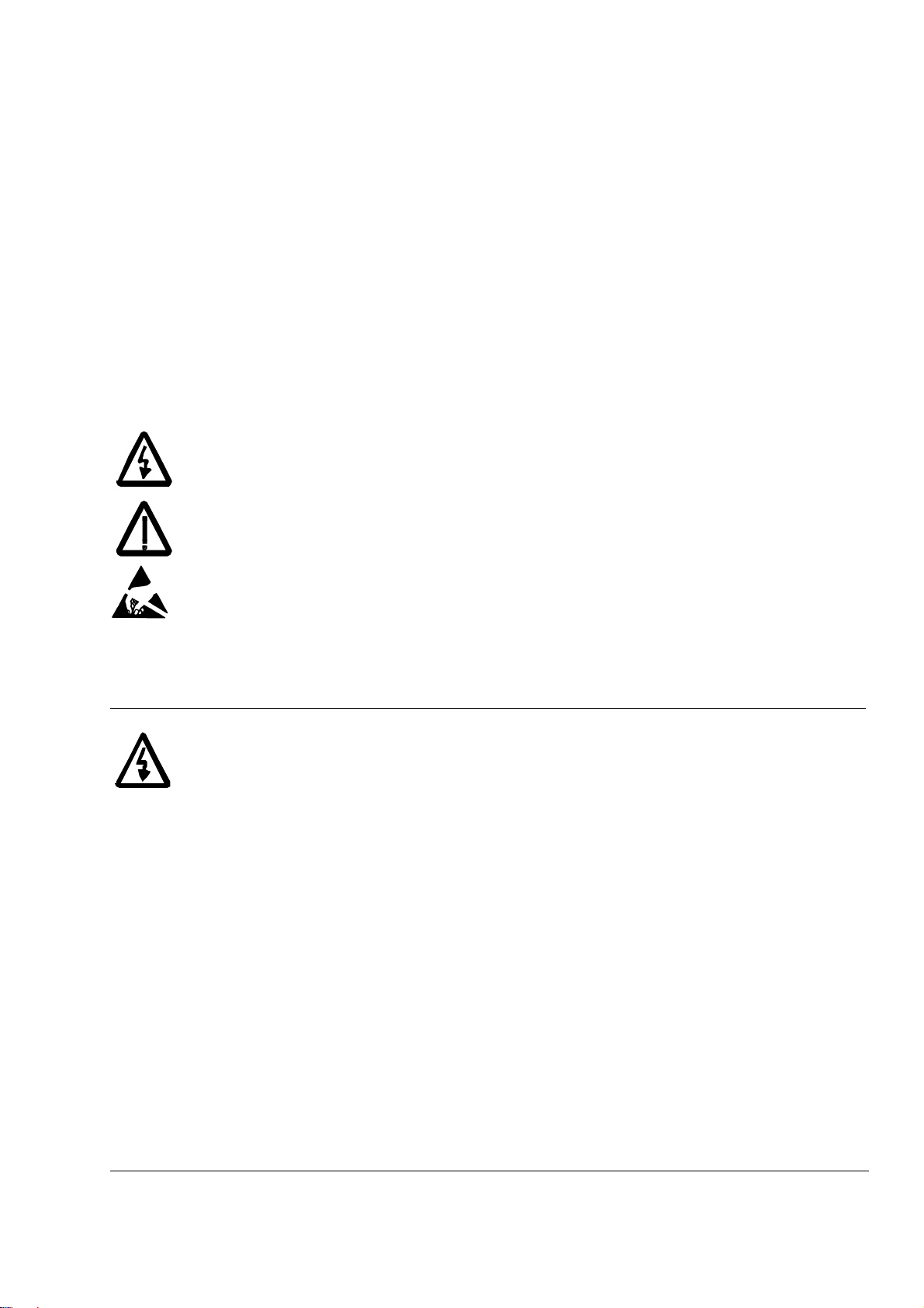
subject. The warning symbols are used as follows:
Dangerous voltage warning warns of high voltage, which can cause physical injury or death
and/or damage to the equipment.
General danger warning warns about conditions, other than those caused by electricity, which
can result in physical injury or death and/or damage to the equipment.
3
Electrostatic sensitive devices warning warn of electrostatic discharge, which can damage
the equipment.
Installation and maintenance work
These warnings are intended for all who work on the drive, motor cable or motor. Ignoring the instructions can
cause physical injury or death and/or damage to the equipment.
WARNING!
1. Only qualified electricians are allowed to install and maintain the drive!
Never work on the drive, motor cable or motor when main power is applied. Always ensure
by measuring with a multimeter (impedance at least 1 Mohm) that:
1. Voltage between drive input phases U1, V1 and W1 and the frame is close to 0 V.
2. Voltage between terminals C+ and D- and the frame is close to 0 V.
Do not work on the control cables when power is applied to the drive or to the external
control circuits. Externally supplied control circuits may cause dangerous voltages inside the
drive even when the main power on the drive is switched off.
Do not make any insulation resistance or voltage withstand tests on the drive or drive
modules.
Isolate the motor cables from the drive when testing the insulation resistance or voltage
withstand of the cables or the motor.
When reconnecting the motor cable, always check that the C+ and D- cables are connected
with the proper terminal.
Note:
The motor cable terminals on the drive are at a dangerously high voltage when the main
power is on, regardless of whether the motor is running or not.
Depending on the external wiring, dangerous voltages (115 V, 220 V or 230 V) may be
present on the relay outputs of the drive system (e.g. RDIO).
DCS550 with enclosure extension: Before working on the drive, isolate the whole drive
system from the supply.
Safety instructions
3ADW000379R0301 DCS550 Manual e c
Page 4

4
Grounding
These instructions are intended for all who are responsible for the grounding of the drive. Incorrect grounding
can cause physical injury, death and/or equipment malfunction and increase electromagnetic interference.
Printed circuit boards and fiber optic cables
These instructions are intended for all who handle the circuit boards and fiber optic cables. Ignoring the
following instructions can cause damage to the equipment.
WARNING!
Ground the drive, motor and adjoining equipment to ensure personnel safety in all
circumstances, and to reduce electromagnetic emission and pick-up.
Make sure that grounding conductors are adequately sized and marked as required by safety
regulations.
In a multiple-drive installation, connect each drive separately to protective earth (PE ).
Minimize EMC emission and make a 360° high frequency grounding (e.g. conductive
sleeves) of screened cable entries at the cabinet lead-through plate.
Note:
Power cable shields are suitable as equipment grounding conductors only when adequately
sized to meet safety regulations.
As the normal leakage current of the drive is higher than 3.5 mA
or 10 mADC (stated by EN
AC
50178, 5.2.11.1), a fixed protective earth connection is required.
WARNING!
The printed circuit boards contain components sensitive to electrostatic discharge. Wear a
grounding wristband when handling the boards. Do not touch the boards unnecessarily.
Use grounding strip:
ABB order no.: 3ADV050035P0001
WARNING!
Handle the fiber optic cables with care. When unplugging optic cables, always grab the
connector, not the cable itself. Do not touch the ends of the fibers with bare hands, as the fiber
is extremely sensitive to dirt. The minimum allowed bend radius is 35 mm (1.38 in.).
Safety instructions
3ADW000379R0301 DCS550 Manual e c
Page 5

Mechanical installation
These notes are intended for all who install the drive. Handle the unit carefully to avoid damage and injury.
WARNING!
DCS550 size F4: The drive is heavy. Do not lift it alone. Do not lift the unit by the front cover.
Place it only on its back.
Make sure that dust from drilling does not enter the drive when installing. Electrically
conductive dust inside the unit may cause damage or lead to malfunction.
Ensure sufficient cooling.
Do not fasten the drive by riveting or welding.
Operation
These warnings are intended for all who plan the operation of the drive or operate the drive. Ignoring the
instructions can cause physical injury or death and/or damage to the equipment.
WARNING!
Before adjusting the drive and putting it into service, make sure that the motor and all driven
equipment are suitable for operation throughout the speed range provided by the drive. The
drive can be adjusted to operate the motor at speeds above and below the base speed.
Do not control the motor with the disconnecting device (disconnecting mains); instead, use
5
the control panel keys
Mains connection
You can use a disconnect switch (with fuses) to disconnect the electrical components of the
drive from the mains for installation and maintenance work. The type of disconnect switch
used must be as per EN 60947-3, Class B, so as to comply with EU regulations, or a circuitbreaker type which switches off the load circuit by means of an auxiliary contact causing the
breaker's main contacts to open. The mains disconnect must be locked in its "OPEN"
position during any installation and maintenance work.
EMERGENCY STOP buttons must be installed at each control desk and at all other control
panels requiring an emergency stop function. Pressing the STOP button on the control panel
of the drive will neither cause an emergency stop of the motor, nor will the drive be
disconnected from any dangerous potential.
To avoid unintentional operating states, or to shut the unit down in case of any imminent
danger according to the standards in the safety instructions it is not sufficient to merely shut
down the drive via signals "RUN", "drive OFF" or "Emergency Stop" respectively "control
panel" or "PC tool".
Intended use
The operating instructions cannot take into consideration every possible case of
configuration, operation or maintenance. Thus, they mainly give such advice only, which is
required by qualified personnel for normal operation of the machines and devices in industrial
installations.
If in special cases the electrical machines and devices are intended for use in non-industrial
installations - which may require stricter safety regulations (e.g. protection against contact by
children or similar) - these additional safety measures for the installation must be provided by
the customer during assembly.
Note:
When the control location is not set to Local (L not shown in the status row of the display),
the stop key on the control panel will not stop the drive. To stop the drive using the control
and , or commands via the I/O board of the drive.
panel, press the LOC/REM key and then the stop key
.
Safety instructions
3ADW000379R0301 DCS550 Manual e c
Page 6

6
Table of contents
DCS550 Manuals.................................................................................................................................................2
Safety instructions................................................................................................................................................ 3
Table of contents ................................................................................................................................................. 6
Introduction.......................................................................................................................................................... 8
The DCS550........................................................................................................................................................ 9
General...................................................................................................................................................... 9
Overview Main circuit and control............................................................................................................ 11
Environmental Conditions........................................................................................................................ 12
Type code................................................................................................................................................ 13
Voltage ratings......................................................................................................................................... 13
Current ratings......................................................................................................................................... 14
Dimensions and weights.......................................................................................................................... 16
Mechanical installation....................................................................................................................................... 19
Cabinet installation .................................................................................................................................. 20
Planning the electrical installation......................................................................................................................21
Drive connection and wiring example...................................................................................................... 22
Installation components........................................................................................................................... 24
Cabling..................................................................................................................................................... 29
⑥ Cooling fans ........................................................................................................................................ 32
Electrical installation .......................................................................................................................................... 33
Power connections .................................................................................................................................. 34
Drive interfaces........................................................................................................................................ 36
Installation checklist................................................................................................................................. 38
Electronic board details......................................................................................................................................39
Terminal locations ................................................................................................................................... 39
Table of used boards............................................................................................................................... 40
Control board SDCS-CON-F ................................................................................................................... 41
Power Interface board SDCS-PIN-F........................................................................................................ 44
OnBoard field exciters SDCS-BAB-F01 and SDCS-BAB-F02 ................................................................ 46
Accessories........................................................................................................................................................ 49
① Line reactors (L1)................................................................................................................................ 49
② Semiconductor fuses (F1)................................................................................................................... 55
③ EMC filters (E1)................................................................................................................................... 57
④ Auxiliary transformer (T2) for converter electronics and fan............................................................... 57
Start-up.............................................................................................................................................................. 58
Commissioning ........................................................................................................................................ 58
Macros ..................................................................................................................................................... 62
Firmware description..........................................................................................................................................73
Start / stop sequences............................................................................................................................. 73
Excitation ................................................................................................................................................. 74
Table of contents
3ADW000379R0301 DCS550 Manual e c
Page 7

DC-breaker...............................................................................................................................................76
Dynamic braking.......................................................................................................................................77
Digital I/O configuration............................................................................................................................79
Analog I/O configuration...........................................................................................................................83
Serial field bus communication...........................................................................................................................87
CANopen communication with fieldbus adapter RCAN-01......................................................................87
ControlNet communication with fieldbus adapter RCNA-01 ....................................................................91
DeviceNet communication with fieldbus adapter RDNA-01.....................................................................94
Ethernet/IP communication with fieldbus adapter RETA-01....................................................................97
Modbus (RTU) communication with fieldbus adapter RMBA-01 ...........................................................100
Modbus/TCP communication with fieldbus adapter RETA-01...............................................................102
Profibus communication with fieldbus adapter RPBA-01.......................................................................103
ProfiNet communication with fieldbus adapter RETA-02.......................................................................107
Switch on sequence ...............................................................................................................................108
Data set table .........................................................................................................................................108
AP (Adaptive Program).....................................................................................................................................109
What is AP?............................................................................................................................................109
DWL AP..................................................................................................................................................113
Function blocks ......................................................................................................................................118
Winder ..............................................................................................................................................................130
7
Winder blocks.........................................................................................................................................130
Winder macros .......................................................................................................................................136
Winder commissioning ...........................................................................................................................145
Signal and parameter list..................................................................................................................................148
Parameter group list...............................................................................................................................149
Signals....................................................................................................................................................151
Parameters.............................................................................................................................................176
DCS Control Panel...........................................................................................................................................264
Fault tracing......................................................................................................................................................270
Converter protection...............................................................................................................................270
Motor protection .....................................................................................................................................273
Display of status, fault messages and error codes ................................................................................279
Fault signals (F)......................................................................................................................................280
Alarm signals (A)....................................................................................................................................288
Notices ...................................................................................................................................................295
Appendix A: Quick start-up diagrams...............................................................................................................296
Drive configuration with reduced components .......................................................................................296
I/O connections ......................................................................................................................................298
Appendix B: Firmware structure diagrams.......................................................................................................299
Appendix C: Index of signals and parameters..................................................................................................303
Table of contents
3ADW000379R0301 DCS550 Manual e c
Page 8

8
Introduction
Chapter overview
This chapter describes the purpose, contents and the intended use of this manual.
Before You Start
The purpose of this manual is to provide you with the information necessary to control and program the drive.
Study carefully the Safety instructions
the drive. Read this manual before starting-up the drive.
Note:
This manual describes the standard DCS550 firmware.
What this manual contains
The Safety instructions are at the beginning of this manual.
Introduction
The DC
Mechanical installation
Planning the electrical installation
Electrical installation
Electronic board details
Accessories
Start-up
Firmware description
Serial field bus communication
AP (Adaptive Program)
Winder
Signal and parameter list
DCS Control Panel
Fault tracing
Appendix A: Quick start-up diagrams
Appendix B: Firmware structure diagrams
Appendix C: Index of signal and parameters
, the chapter you are currently reading, introduces you to this manual.
S550, this chapter describes the basic properties of the DCS550.
, this chapter describes the mechanical installation of the DCS550.
, this chapter describes the electrical installation of the DCS550.
, this chapter describes the electronics of the DCS550.
, this chapter describes the accessories for the DCS550.
, this chapter describes the basic start-up procedure of the DCS550.
, this chapter describes how to control the DCS550 with standard firmware.
, this chapter describes the communication capabilities of the DCS550.
, this chapter describes the basics of AP and instructs how to build an application.
, this chapter describes the winder and instructs how to use the winder blocks of the DCS550.
, this chapter contains all signals and parameters.
, this chapter describes the handling of the DCS Control Panel.
, this chapter describes the protections and fault tracing of the drive.
at the beginning of this manual before attempting any work on or with
, this chapter describes how to plan the electrical installation of the DCS550.
Introduction
3ADW000379R0301 DCS550 Manual e c
Page 9

The DCS550
A
A
A
A
A
A
A
A
A
A
A
A
A
A
A
A
A
A
A
A
A
A
A
A
A
A
A
A
A
A
A
A
A
A
A
A
Chapter overview
This chapter describes the basic properties of the DCS550.
General
ABB Drive Service
In order to offer the same after sales service to our customer around the
world, ABB has created the DRIVE SERVICE CONCEPT. ABB’s after
sales service is globally consistent due to common targets, rules and the
way of operation. This means for our customers simply visit the ABB
drive service homepage at www.abb.com/drivesservices
DC drives worldwide Service Network
Country Local ABB Service Town Service Phone No.
rgentina
ustralia
ustria
Belgium
Brazil
Canada
China
Czech Republic ABB S.R.O. PRAHA +42 02 34 32 23 60
Finland
Finland
Finland
France
Germany
Greece
Ireland
Italy
Korea, Republic ABB Ltd., Korea CHONAN +82 (0) 4 15 29 22
Malaysia
Mexico
Netherlands
New Zealand
Poland
Russia
Switzerland
Singapore
Slovakia
South Africa
Spain
Taiwan
Thailand
Turkey
USA
Venezuela
sea Brown Boveri S.A. BUENOS AIRES +54 (0) 12 29 55 00
BB NOTTING HILL +61 (0) 3 85 44 00 00
BB AG WIEN +43 1 60 10 90
BB N.V. ZAVENTEM
BB Ltda. OSASCO +55 (0) 11 70 84 91 11
BB Inc. SAINT-LAURENT +1800 865 7628
BB China Ltd BEIJING +86 40 08 10 88 85 - 24h service
BB Oy Service KUUSANKOSKI +35 8 10 22 51 00
BB Oy Product Service HELSINKI +35 8 10 22 20 00
BB Oy Service NOKIA +35 8 10 22 51 40
BB Automation
BB Process Industry
BB Process Industries MANNHEIM +49 18 05 22 25 80
BB SA METAMORPHOSSIS +30 69 36 58 45 74
BB Ireland Ltd. TALLAGHT +35 3 14 05 73 00
BB MILAN +39 02 90 34 73 91
BB Malaysia Sdn. Bhd. KUALA LUMPUR +60 3 56 28 42 65
BB Sistemas S.A. DE C.V. TLALNEPANTLA +52 53 28 14 00
BB B.V. ROTTERDAM +31 1 04 07 88 66
BB Service ltd
BB Centrum IT Sp.zo.o
BB Automation LLC MOSCOW +74 95 96 0
BB AG DÄTTWIL +41 5 85 86 87 86
BB Industry Pte Ltd SINGAPORE +65 67 76 57 11
BB Elektro s.r.o. BANSKA BYSTRICA +42 19 05 58 12 78
BB South Africa (Pty) Lt JOHANNESBURG +27 1 16 17 20 00
BB Automation Products BARCELONA +34 9 37 28 73 00
BB Ltd. TAIPEI 105 +88 62 25 77 60 90
BB Limited SAMUTPRAKARN +66 27 09 33 46
BB Elektirk Sanayi A.S ISTANBUL +90 2 16 36 52 90
BB Industrial Products NEW BERLIN
BB S.A. CRCS +58 (0) 22 38 24 11 / 12
MONTLUEL
from abroad France
UCKLAND +64 92 76 60 16
WROCLAW
LODZ
.
+32 27 18 64 86
+32 27 18 65 00 - 24h service
+33 1 34 40 25 81
+0810 02 00 00
+48 42 61 34 96 2
+48 42 29 93 91 39 5
+1 26 27 85 32 00
+1 262 435 7365
9
The DCS550
3ADW000379R0301 DCS550 Manual e c
 Loading...