

Page 1

Catalog
ABB DC Drives
DCS550, 20 A to 1000 A
Page 2
©
2
0
1
1
A
B
B
A
u
t
o
m
a
t
i
o
n
P
r
o
d
u
t
G
m
b
H
-
A
l
l
R
i
g
h
t
R
e
e
r
e
d
3ADW 000 377 R0201 / April 2011
System configuration
WINDOWS 98, NT, 2000, XP
Acrobat Reader 4.0 or higher
Internet Explorer 5.0 or higher
I
f
t
h
e
C
D
R
O
M
w
o
n
’
t
s
t
a
r
t
a
u
t
o
m
a
t
i
c
a
l
l
y
p
l
e
a
s
e
e
x
e
c
u
t
e
S
T
A
R
T
.
B
A
T
System confirmation
Win2000, WinXP
Before installation of PC tools
remove previous version by
CONTROL PANEL of your
PC
Read more details in
Quick Guide 3ADW000191
Content
This CD ROM provides
information about DCS550 and
contains PC tools:
DWL 2.93 for DC drives
+Commissioning Wizard 1.0
+DWL AP 2.2
FDT 2.2 Firmware
download kit
+ workspace
Firmware 1.1
DCS550
Ver.: 1.10
System confirmation
Win7, Win2000, WinXP
Before installation of PC tools
remove previous version by
CONTROL PANEL of your PC
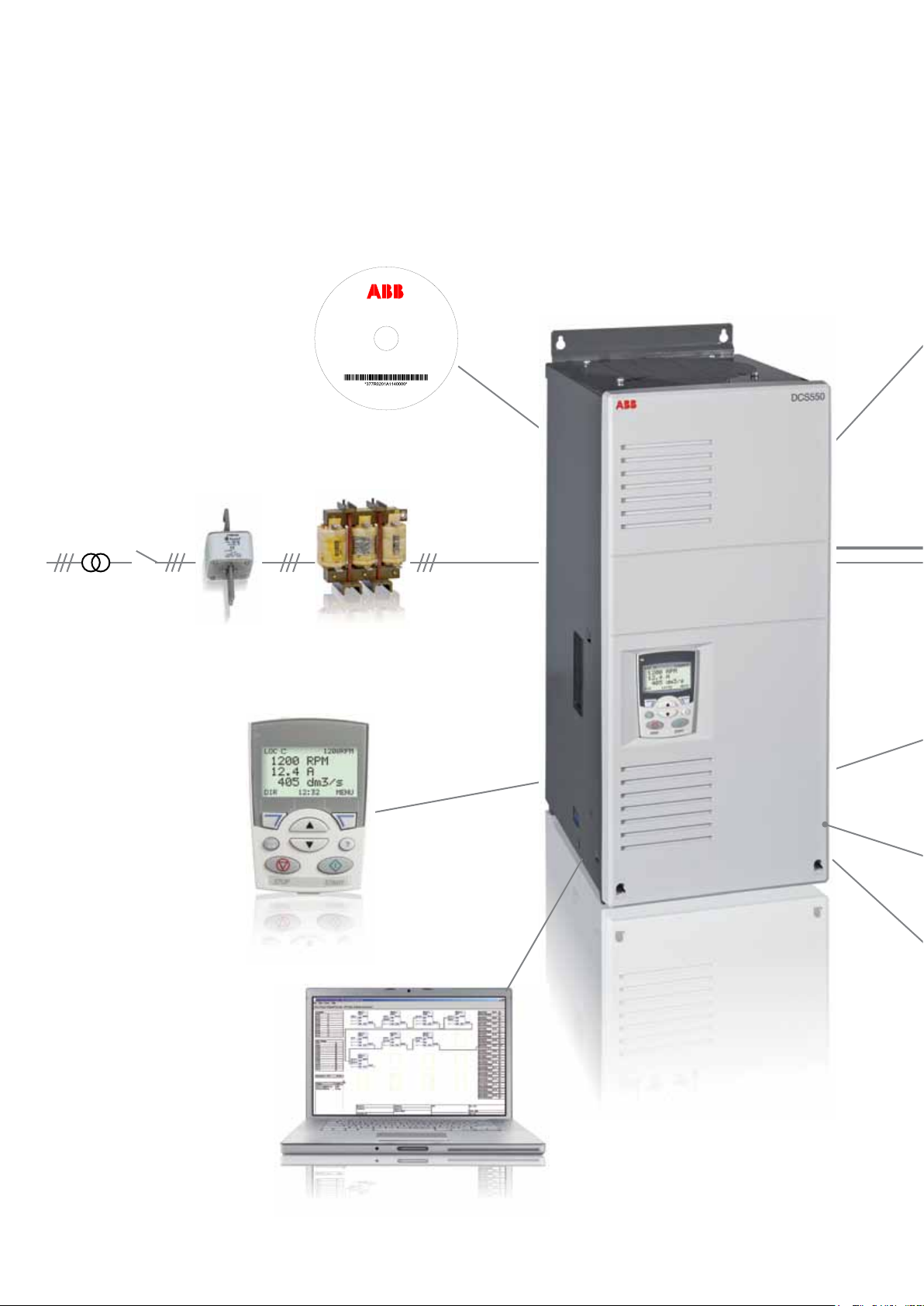
Flexibly geared to all the requirements of modern-day machinery
manufacturers
c
s
s
s
Startup and
maintenance software
Used from drive startup
and configuration to daily
use and process tuning
v
UR fuses Three phase line chokes
Assistant control panel
The assistant control panel
features a multilingual alphanumeric display for easy drive
programming. The control
panel has various assistants
and a built-in help function to
guide the user.
Adaptive Programming
Adaptive Programming
is easy and fast because
there is a graphical support.
2 3ADW000378R0101 | DCS550 Technical catalog e a
Page 3

Fieldbus adapter
modules
The pluggable fieldbus
options allow connection to most automation
systems.
A single cable replaces
complex conventional
cabling.
With its compact dimensions and robust
technology, the DCS550 is an ideal drive
solution for machinery manufacturers – both in
new installations or as a replacement for older
analog devices.
Integrated “winder”, high-performance
field supply and various interfaces provide
machinery manufacturers with a maximum of
flexibility in terms of machine integration.
DC motor
Interface extension modules
The pluggable I/O modules
extend the basic I/Os.
On-board field exciter
Integrated on-board field
exciter reduces hardware and installation
work.
Integrated macros
Most frequent parameter settings covered
by macros for easy
commissioning.
Contents
Overview 2
Contents 3
Designed for essential requirements 4
Flexibility for different applications 5
Smart human-drive interface 6
Standard firmware 7
PC tool for easy start-up and maintenance 8
Winder function required? 9
How to select a drive 10
Standard interface and extensions 11
How to select the motor voltage 12
Technical data, dimensions and weights 13
Line reactors L1 14
Fuse connections 15
Environmental conditions 16
Service 17
DCS family - the range for all demands 18
Notes 19
DCS550 Technical catalog e a | 3ADW000378R0101 3
Page 4

Designed to meet the essential requirements of machinery
manufacturers
DCS550 – The highlights
– Compact dimensions
For installations with limited space
– Integrated high performance three phase field exciter up to 35 A
Fits all available motors without additional installations
– “Winder” with commissioning assistant
For easy and fast adaptation to different applications
– Different fieldbus interfaces (incl. EtherCAT, Profinet…)
For easy integration into automation
– Additional PID-controller
For overriding control functions (e. g. pressure or
level control)
– Adaptive programming with Drive AP, ABB’s graphical PC-tool
For easy implementation of additional functions
– Various start-up assistants and auto-tune functions
For fast commissioning
– Large control panel
For straight forward and self-explanatory operation
– Rugged design
For rough environments, high reliability
– Worldwide service
Local service in more than 60 countries
Easy to use
The basic version of the DCS550 is already equipped with a
large number of standard hardware interfaces like an encoder,
an analog tachogenerator and four analog input devices.
Since the basic unit includes all important functions almost all
applications are covered – options are not necessary.
The single-volume documentation provides comprehensive
information on the unit, firmware and hardware. The guided
start-up and complementary support functions reduce startup times to a minimum. The grouped structure of the parameters provides easy and clearly arranged navigation within the
various features and functions. Error messages and help texts
are displayed in plaintext in the user’s native language. The reduced need for training is an additional advantage created by
the synergies and similarities with ABB’s DCS800 converter
and ABB AC-drives.
Fieldexciter connection
DCS550 Control panel
Analog output, 2 x AO
Analog input, 4 x AI
Tacho input /10 ... 270 V
Armature Connection
4 3ADW000378R0101 | DCS550 Technical catalog e a
R-Fieldbus module
R-IO extension module
R-IO extension module
Encoder interface
Digital input, 8 x DI
Digital output, 4 x D0
Digital output, Relay
AC Connection
DCS550 converter module
Page 5

Flexibility for different applications
DCS550 – Extensive applications
– Extruders
– Sugar centrifuges
– Wire drawing machines
– Coating lines
– Printing machines
– Presses
– Tools machines main drives
– Food processing machines
– Woodworking (wooden products and MDF industry)
– Retrofit of analog DC-technology
Modern DC-drives – More up-to-date than ever
Today, DC-drive technology is more up-to-date than ever.
Their attractive cost-performance ratio and functional advantages such as high torque at low speed, light weight and low
power loss, turn DC-drives into the preferred solution for many
applications. As far as innovation is concerned ABB’s DCdrives match the same high standards as ABB’s AC-drives.
Easy upgrade of installed older converters
The machines are frequently still in very good condition, but
spare parts and know-how for the installed power electronics
are no longer available.
With the DCS550, existing machines can be kept in operation
by replacing the old drive.
Short downtimes and low costs for the retrofit are additional
advantages of an upgrade of existing machinery.
DCS550 Technical catalog e a | 3ADW000378R0101 5
Page 6

Smart human-drive interface
General
All units are equipped with the DCS550 Control Panel. It can
be snapped into place on the power converter module or
installed in the switchgear cubicle door by means of a mounting kit.
Control panel: high level of convenience included
The assistant control panel is part of the basic unit. It offers
a multi-language alphanumeric display (EN, DE, ES, FR, IT)
with a multilingual help function. The large graphic display
allows the user to freely select actual and set values. Another
additional advantage: the user can call up a list of all changed
parameters. The control panel can also store parameters as a
security backup or copy them for use in other converters.
Panel mounting kits
To attach the control panel to the outside of a larger enclosure, two panel mounting kits are available. A simple and
cost-efficient installation is possible with the ACS/H-CP-EXT
kit, while the JPMP-01 kit provides a more user-friendly solution, including a panel platform that enables the panel to be
removed in the same way as a drive-mounted panel. The
panel mounting kits include all hardware required, including
3 m extension cables and installation instructions.
– Startup Assistant
– Fault logger function
– Plain text for fault logger, faults and alarms
– Shows actual values in physical units
– Backup and Copy function for parameter
– Compare function for parameters
– Real time clock
- Help function
- Multilingual
6 3ADW000378R0101 | DCS550 Technical catalog e a
Page 7

Standard Firmware for scalable control and functionality
α
≥
Basic firmware
DCS550 firmware includes the basic functions of speed
control, armature current, field current and motor voltage. The
design of the drive logic enables a drive reaction defined by
Profibus standard, but can also configured to adapt classic
command structures.
Macros
The DCS550 is equipped with seven different macros to cover
the most frequent parameter settings.
Macros are pre-programmed parameter sub-sets. During
start-up, the drive can be configured easily without changing individual parameters. The functions of all inputs and
several outputs and of allocations in the control structure are
influenced by the selection of a macro. The means whether
the drive is speed-controlled or torque-controlled, whether
supplementary references are processed, which actual values
are available at the analog outputs, which reference value
sources are used etc. is already defined in the macro.
Functions of basic firmware
– Different speed ramp function
– Speed control
– Torque control
– Armature current control
– Field current control
– Automatic field weakening
– E-stop function according to Profibus standard
– Interface for fieldbus
– Programmable digital and analogue outputs
– 16 blocks Adaptive Program
– Converter protection (temperature, voltage,...)
Motor protection features
– Stall protections
– Thermal motor model
– Klixon supervision
– Speed feedback error
– Over speed
– Armature current ripple
– Armature over current
– Minimum field current
Example: STANDARD macro
DCS550 Technical catalog e a | 3ADW000378R0101 7
Page 8
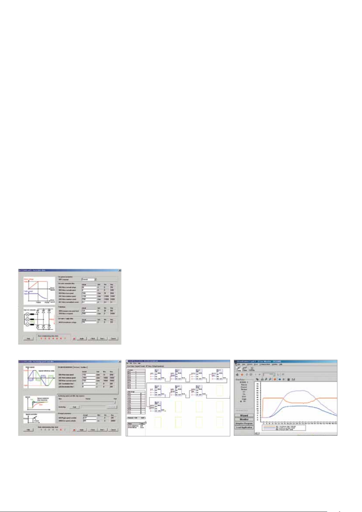
PC tool for easy start-up and maintenance
Useful features
DriveWindow Light
The user-friendly start-up and maintenance tool for the world
of ABB-drives supports both ABB’s DC-drives and AC-drives.
DriveWindow Light is a PC software package for easy and
fast start-up and maintenance of DCS550 converters and is
part of the basic package. In offline-mode, all parameters can
be set from the user’s office desk. The parameter browser
can both display and save parameters on the computer. A
comparison feature can compare and align current values with
a stored set of parameters. With the “Local”-feature, the drive
can be controlled as well. At the same time, up to four display
values can be visualized graphically. DriveWindow Light also
includes an assistant for guided start-up, winder functions as
well as the AP-tool for block programming.
Start-up assistant
The DriveWindow Light start-up assistant for the DCS550
provides valuable support during commissioning via an interactive dialog. The individual steps of the start-up process
are pre-defined in the right order and all required parameters
are displayed. The “Basic”-feature captures motor and connection data and adjusts the controller automatically. The
“Advanced”-feature supports the start-up of serial communication (fieldbus) and winder functions. The context-sensitive
help function is always available.
Adaptive Programming (AP):
Adaptive Programming is included in the basic package.
With the help of 16 functional blocks users can develop, test
and document their own programs easily in graphical mode.
The „Adaptive Programming“ (AP) function allows the implementation of additional features.
Modifications can be configured with either the control panel
or with the help of the graphical interface of DriveWindow
Light AP.
The main features of DriveWindow Light AP are:
– 16 programmable function blocks
– Available functions:
– Logical: AND, OR and XOR
– Mathematical: ADD, MUL, DIV, ABS, MAX and MIN
– Other: timer, switch, comparator, filter, SR, PI and
user-defined warnings or faults
– Freely definable execution order
– Easy documentation
Start-up Assistant
Speed Controller Autotuning
Adaptive Programming
Content CD:
The CD ROM provides information about DCS550
and contains PC tools:
– DriveWindow Light for DC drives +
Commissioning Wizard + DWL AP
– FDT Firmware download kit + workspace
– Firmware
Trending
8 3ADW000378R0101 | DCS550 Technical catalog e a
Page 9

Winder function required?
F
T
D
F
T
D
Integrated winder functions
The DCS550 is equipped with a winder function featuring
pre-defined macros for the four most commonly used winder
types:
Velocity control
Calculates the diameter and rotation speed setpoint value.
The diameter is used to adjust the speed controller to all
winding sizes. There is no tension control. All other macros
are included in this basic structure.
Indirect tension control
Controls the tension with the help of preset charts for friction
and moment of inertia (open loop).
This structure provides a very robust control behavior because no physical tension measurement is required.
Dancer control
Controls the tension with the weight of the dancer roll
(closed loop).
The dancer has to be kept in the right position with additional
speed set values. The PID-controller of the DCS550 can also
control the positioning of the dancer roll. The position of the
dancer roll is transmitted to the controller as an analog actual
value.
Commissioning assistant
For an easy winder set-up, all different winder types can be
configured and commissioned using a graphical assistant.
The assistant is part of DriveWindows Light PC-tool.
The rating for friction and inertia can be determined by auto
tuning.
Direct tension control
Closed loop for physical value of tension
The tension is measured with a load cell and transferred to
the drive as an analog actual value. The DCS550 is equipped
with a free PID-controller that can be integrated into the control loop with the “Tension Control” macro.
Example: direct tension control (closed loop)
Winder MacrosWinder Assistant
DCS550 Technical catalog e a | 3ADW000378R0101 9
Page 10

How to select a drive
Many of the features for DCS550 drives are built-in as standard providing easy selection.
Every drive is equipped with
– Assistant Control panel
– CD ROM with PC commissioning assistant and DWL/ AP
programming PC tool (PC requires COM port)
– Quickguide manual in 5 language En,DE,IT,FR,ES
– Marking CE and cUlus
– ON board field exciter, rating see table
The control board and power interface board are coated.
Cable marking C and tin plated Cu bars inside, Protection
class IP00.
Available as options
– R-fieldbus modules
– additional R I/O modules
– semiconductor fuses
– line reactors
– EMC Filters
To choose the right drive for your application, please refer to
the ratings table on page 12. The selected drive has a unique
type designation, which identifies the drive by construction,
power and voltage range.
Type designation: DCS550 - S0y - xxxx - 05
DCS550-S0y-xxxx-05
– DCS550 = Product series
– S0 = DC drive converter module
– y = 1 = single bridge/ motor operation
= 2 = double bridge motor + regen operation
– xxxx = rated current (main bridge armature circuit) double check
suitable duty cycles rated field current, see table
– 05 = 230 V
Options are ordered via Id code of the price list.
... 525 VAC supply
AC
10 3ADW000378R0101 | DCS550 Technical catalog e a
Page 11
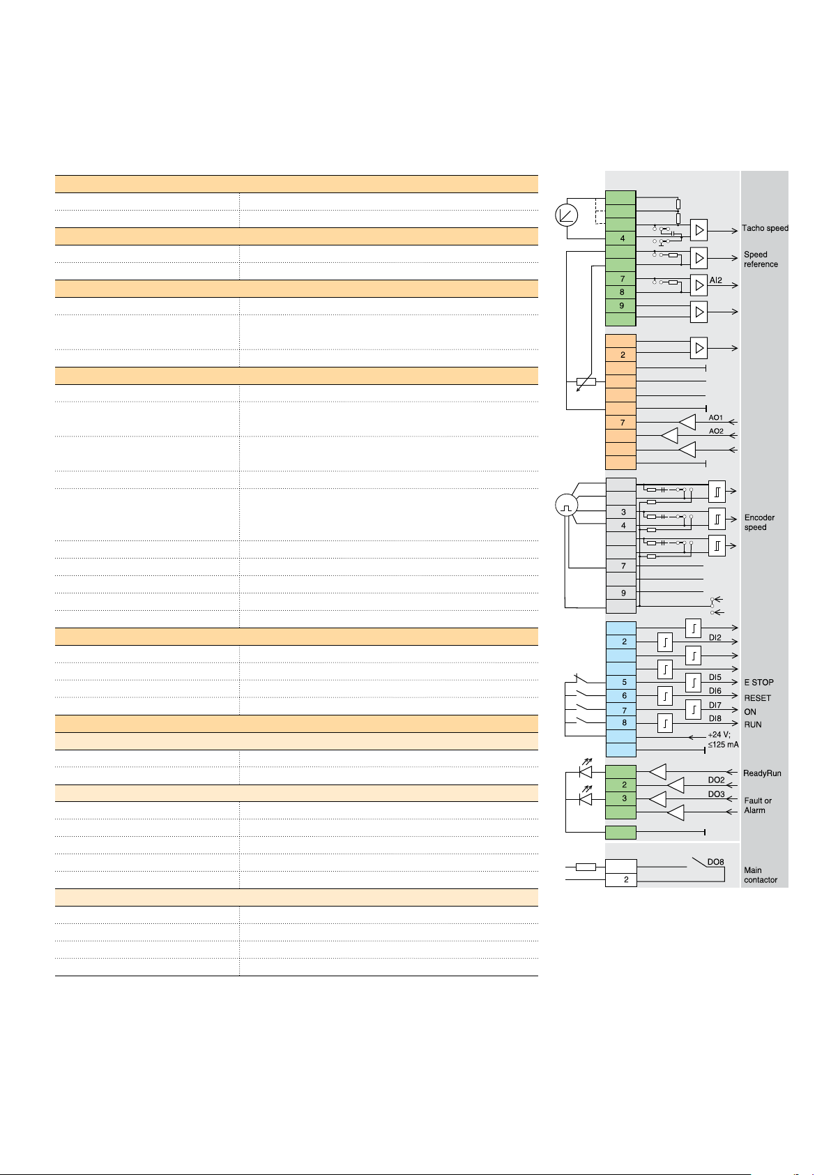
Standard interface and extensions for comprehensive connectivity
Mains connection
Mains 3-phase 230 VAC - 525 VAC; -15 % / +10 %
Rated frequency 50 Hz or 60 Hz
Field exciter
Supply voltage Internally connected to the mains
Hardware Completely integrated 3-phase OnBoard field exciter
Operating conditions
Degree of protection IP 00
EMC Fulfilling EN 61800-3 in accordance with
3ADW 000 032
Compliance CE, cULus
Control interfaces
Auxiliary voltages 115 V
, 230 VAC, 230 V
AC
DC
PC-tools DriveWindow Light, DWL AP, start-up assistant, winder as-
sistant, help function
DCS550 Control Panel As standard, several languages, start-up assistant, help
function
Status display Seven-segment display as standard
Analog I/O 4 AI (15 bit + sign);
3 AO (11 bit + sign; two are freely programmable, one is
fixed for armature current)
Digital I/O 8 DI, 5 DO (one for mains breaker)
Motor temperature 1 PTC
Analog tacho input As standard
Encoder input As standard for 5 V and 24 V encoders
Option slots two slots for analog and digital I/O plug-in options
Special firmware functions
Adaptive Program 16 freely programmable function blocks
PID controller Freely usable PID controller
Macros 10 pre-defined macros for fast commissioning
winder macros 4 pre-defined winder macros
Control and communication options
Analog & digital plug-in options
1 * RAIO 2 AI, 2 AO
2 * RDIO 3 DI, 2 DO each
Classic fieldbusses
RCAN-01 CANopen
RCNA-01 ControlNet
RDNA-01 DeviceNet
RMBA-01 Modbus (RTU)
RPBA-01 Profibus
Ethernet fieldbuses
RECA-01 EtherCat
RETA-01 Ethernet/IP and Modbus/TCP
RETA-02 Profinet
t
230V
E
K1
SDCS-CON-F
±90...±270 V
X1:1
±
30...±90 V
2
±
8...±30 V
3
S1
3
S1
6
5
S2
3
4
6
S3
3
4
10
X2:1
3
4
5
6
8
9
10
X3:1
121
100nF
2
10k
121
100nF
10k
5
121
100nF
6
10k
8
10
Sense 0 V
Sense 5 V
Power
X4:1
3
4
9
10
1
X5:
4
8
SDCS-PIN-F
X96:1
Firmware
-
ATACH
1
+
4
-
AI1
250
+
-
250
+
-
AI3
+
-
AI4
+
GND
+10V
-10V
GND
I-act
GND
ChA
+
S4
3
2
1
ChA
-
ChB
+
S4
6
5
4
ChB
-
ChZ
+
9
7S48
ChZ
-
GND
S4
10
5V
11
24V
12
DI1
DI3
DI4
DO1
DO4
GND
B22_001_0_a.dsf
DCS550 Technical catalog e a | 3ADW000378R0101 11
Page 12
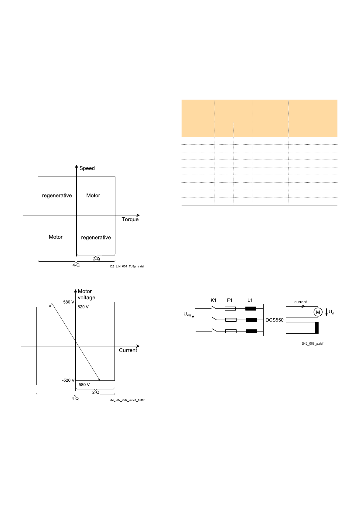
How to select the motor voltage
Reference variables
The voltage characteristics are shown in the table beside. The
DC voltage characteristics have been calculated using the following assumptions:
= rated input terminal voltage, 3-phase
– U
VN
– Voltage tolerance ±10 %
– Internal voltage drop approx. 1 %
– If a deviation or a voltage drop has to be taken into con-
sideration in compliance with IEC and VDE standards, the
output voltage or the output current must be reduced in
accordance with the table on the right.
The bridge type 2-Q or 4-Q has an influence on the maximum
motor voltage. See table below.
System
connection
voltage
U
[V]
230 265 240 310 05
380 440 395 510 05
400 465 415 540 05
415 480 430 560 05
440 510 455 590 05
460 530 480 620 05
480 555 500 640 05
500 580 520 670 05
525 610 545 700 05
VN
DC voltage
(recommended)
U
dmax 2-Q
[V]
U
dmax 4-Q
[V]
Ideal DC
voltage with-
out load
U
di0
[V]
Recommended
DCS800
voltage class
motor and regenerative operation
If armature voltages higher than recommended are requested,
please check carefully whether your system is still working
under safe conditions.
The maximum output voltage of a 4-Q drive can be increased
up to the level of U
. Thus the torque reversal from mo-
dmax 2-Q
toring mode to generating mode increases up to 300 ms. This
lowers the dynamics of the drive and is only recommended for
non-dynamic applications (e.g. E-Stop function).
Example: maximum motor voltage U
for 500 VAC supply voltage U
dmax
VN
The power section of the converters is available as a single
(2-Q) bridge or double (4-Q) bridge. 4-Q drives are required
for regenerative breaking.
12 3ADW000378R0101 | DCS550 Technical catalog e a
Page 13

Technical data, dimensions and weights
Single bridge (2-Q Drive), 230 - 525 V -15 / +10 %
[A] IF [A] Fan supply Dimensions
I
A
20 1 - 12 no fan 370 x 270 x 220 11 9 12 0,18 DCS550-S01-0020-05 F1
45 internal 21 26 0,28 DCS550-S01-0045-05
65 internal 30 38 0,32 DCS550-S01-0065-05
90 internal 42 52 0,39 DCS550-S01-0090-05
135 1 - 18 115 / 230 V 370 x 270 x 270 16 63 78 0,58 DCS550-S01-0135-05 F2
180 115 / 230 V 84 104 0,76 DCS550-S01-0180-05
225 115 / 230 V 105 131 0,90 DCS550-S01-0225-05
270 115 / 230 V 126 157 1,00 DCS550-S01-0270-05
315 2 - 25 115 / 230 V 459 x 270 x 310 25 146 183 1,12 DCS550-S01-0315-05 F3
405 115 / 230 V 188 235 1,38 DCS550-S01-0405-05
470 115 / 230 V 219 273 1,66 DCS550-S01-0470-05
610 2 - 35 230 V 644 x 270 x 345 38 284 354 1,94 DCS550-S01-0610-05 F4
740 230 V 344 429 2,38 DCS550-S01-0740-05
900 230 V 419 522 2,95 DCS550-S01-0900-05
h x w x d [mm]
Weight
[kg]
Power 400 V
[kW]
Power 525 V
[kW]
Losses
[kW]
Type code Size
Double bridge (4-Q Drive), 230 - 525 V -15 / +10 %
[A] IF [A] Fan supply Dimensions
I
A
25 1 - 12 no fan 370 x 270 x 220 11 10 13 0,20 DCS550-S02-0025-05 F1
50 internal 21 26 0,31 DCS550-S02-0050-05
75 internal 31 39 0,36 DCS550-S02-0075-05
100 internal 42 52 0,42 DCS550-S02-0100-05
150 1 - 18 115 / 230 V 370 x 270 x 270 16 62 78 0,64 DCS550-S02-0150-05 F2
200 115 / 230 V 83 104 0,84 DCS550-S02-0200-05
250 115 / 230 V 104 130 1,00 DCS550-S02-0250-05
300 115 / 230 V 125 156 1,10 DCS550-S02-0300-05
350 2 - 25 115 / 230 V 459 x 270 x 310 25 145 182 1,22 DCS550-S02-0350-05 F3
450 115 / 230 V 187 234 1,54 DCS550-S02-0450-05
520 115 / 230 V 216 270 1,85 DCS550-S02-0520-05
680 2 - 35 230 V 644 x 270 x 345 38 282 354 2,15 DCS550-S02-0680-05 F4
820 230 V 340 426 2,64 DCS550-S02-0820-05
1000 230 V 415 520 3,31 DCS550-S02-1000-05
h x w x d [mm]
Weight
[kg]
Power 400 V
[kW]
Power 525 V
[kW]
Losses
[kW]
Type code Size
IAC = IA * 0.82 + IF * 0.82
Size: F1 F2 F3 F4
DCS550 Technical catalog e a | 3ADW000378R0101 13
Page 14

Line reactors L1
Size Converter type (2-Q) Converter type (4-Q) Line choke 1 %
relative voltage drop
F1 DCS550-S01-0020 DCS550-S02-0025 ND01 1 ND401 4
DCS550-S01-0045 DCS550-S02-0050 ND02 1 ND402 4
DCS550-S01-0065 DCS550-S02-0075 ND04 1 ND403 5
DCS550-S01-0090 DCS550-S02-0100 ND06 1 ND404 5
F2 DCS550-S01-0135 DCS550-S02-0150 ND06 1 ND405 5
DCS550-S01-0180 DCS550-S02-0200 ND07 2 ND406 5
DCS550-S01-0225 DCS550-S02-0250 ND07 2 ND407 5
DCS550-S01-0270 DCS550-S02-0300 ND09 2 ND408 5
F3 DCS550-S01-0315 DCS550-S02-0350 ND09 2 ND408 5
DCS550-S01-0405 DCS550-S02-0450 ND10 2 ND409 5
DCS550-S01-0470 DCS550-S02-0520 ND10 2 ND410 5
F4 DCS550-S01-0610 DCS550-S02-0680 ND12 2 ND411 5
DCS550-S01-0740 DCS550-S02-0820 ND13 3 ND412 5
DCS550-S01-0900 DCS550-S02-1000 ND13 3 ND413 5
Design
fig.
Line choke 4 %
relative voltage drop
Design
fig.
Fig. 1 Fig. 2 Fig. 3
Fig. 4 Fig. 5
14 3ADW000378R0101 | DCS550 Technical catalog e a
Page 15
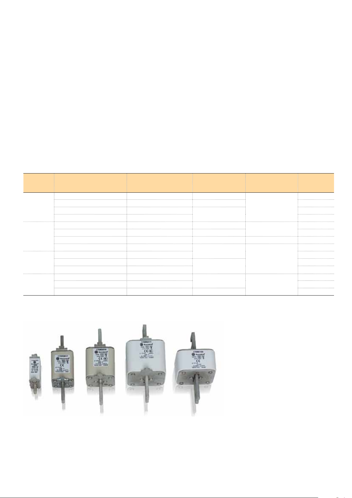
Fuse connections
Semiconductor fuses and fuse holders for AC and DC power lines
The DCS550 converter sizes F1, F2, F3 and F4 with rated
currents up to 1000 A require external line fuses for armature
bridge.
The table assigns the AC fuse types to the converter types
involved. In case the converter needs to be equipped with DC
Recommended fuse connections
Size Converter type (2-Q) Converter type (4-Q) Fuse Type Fuse holder Design
F1 DCS550-S01-0020 DCS550-S02-0025 50A 660V UR OFAX 00 S3L 1
DCS550-S01-0045 DCS550-S02-0050 63A 660V UR 1
DCS550-S01-0065 DCS550-S02-0075 125A 660V UR 1
DCS550-S01-0090 DCS550-S02-0100 1
F2 DCS550-S01-0135 DCS550-S02-0150 200A 660V UR OFAX 1 S3 2
DCS550-S01-0180 DCS550-S02-0200 250A 600V UR 2
DCS550-S01-0225 DCS550-S02-0250 315A 660V UR OFAX 2 S3 2
DCS550-S01-0270 DCS550-S02-0300 500A 660V UR OFAX 3 S3 3
F3 DCS550-S01-0315 DCS550-S02-0350 3
DCS550-S01-0405 DCS550-S02-0450 700A 660V UR 4
DCS550-S01-0470 DCS550-S02-0520 4
F4 DCS550-S01-0610 DCS550-S02-0680 900A 660V UR 3 x 170H 3006 5
DCS550-S01-0740 DCS550-S02-0820 5
DCS550-S01-0900 DCS550-S02-1000 1250A 660V UR 5
fuses according to the instructions use the same type of fuse
used on the AC side now in the plus and minus line (only for
sizes F1...F4). Blade type fuses are used for all the converters of construction type F1...F4 except the converters (610 A,
680 A, 740 A, 820 A, 900 A, 1000 A).
fig.
Fig. 1 Fig. 2 Fig. 3 Fig. 4 Fig. 5
DCS550 Technical catalog e a | 3ADW000378R0101 15
Page 16

Environmental conditions
System connection
Voltage, 3-phase: 230 to 525 V acc. to IEC 60038
Voltage deviation: ±10% continuous; ±15 % short-time *
Rated frequency: 50 Hz or 60 Hz
Static frequency deviation: 50 Hz ±2 %; 60 Hz ±2 %
Dynamic: frequency range: 50 Hz: ±5 Hz; 60 Hz: ± 5 Hz
df/dt: 17 % / s
* = 0.5 to 30 cycles.
Please note: Special consideration must be given to voltage deviation in
regenerative mode.
Degree of protection
Converter module and options
(line chokes, fuse holder, field
supply unit, etc.):
Paint finish
Converter module: RAL 9002
IP 00
Sound pressure level
Size Sound pressure level LP (1 m distance) Vibration
as module enclosed conv. as module
F1 55 dBA 68 dBA
F2 55 dBA 72 dBA
F3 60 dBA 78 dBA
F4 66...70 dBA,
depending on fan
77 dBA
0.5 g, 5...55 Hz
Environmental limit values
Permissible cooling air temperat.
- at converter module air inlet: 0 to +55°C
with rated DC current: 0 to +40°C
w. different DC current +30 to +55°C
- Options: 0 to +40°C
Relative humidity (at 5...+40°C): 5 to 95 %, no condensation
Relative humidity (at 0...+5°C): 5 to 50 %, no condensation
Change of the ambient temp.: < 0.5°C / minute
Storage temperature: -40 to +55°C
Transport temperature: -40 to +70°C
Pollution degree (IEC 60664-1, IEC
60439-1):
Site elevation
<1000 m above M.S.L.: 100%, without current reduction
>1000 m above M.S.L.: with current reduction
2
Product compliance
– CE
– Low Voltage Directive 2006/95/EC — conformity EN61800-5-1 EN60146-1-1
– Machinery Directive 2006/42/EC — in cooperation EN60204-1
– EMC Directive 2004/108/EC — conformity EN61800-3
– Quality assurance system ISO 9001 and Environmental system ISO 14001
– RoHS
– C-Tick
– Pending: UL, cUL 508A or 508C and CSA C22.2 NO. 14-95, GOST R
EMC according to EN 61800-3 (2004)
– Categories C2, C3 or C4 with external EMC filtering or dedicated transformer
16 3ADW000378R0101 | DCS550 Technical catalog e a
Page 17

Service
ABB drive life cycle management model
Maximizing return on investment
At the heart of ABB’s services is its drive life cycle
management model. All services available for ABB low
voltage drives are planned according to this model. For
customers it is easy to see which services are available at
which phase.
Drive specific maintenance schedules are also based on
this four-phase model. Thus, a customer knows precisely
One of the most efficient ways to improve productivity and to
maximize process uptime is to establish a contract which can
include a combination of individual services such as training,
technical support and preventive and corrective maintenance.
Reduced environmental impact
Before purchasing a drive, ABB offers an energy appraisal
to determine which applications can benefit from the use of
drives. During operation and maintenance, tuning of the drive
maximizes its energy savings. Additionally, when the drive life
cycle is complete, ABB can ensure that the drive is disposed
of in a way that meets all local environmental regulations.
Enhanced safety
Seeking advice from ABB at the selection and dimensioning
stage helps ensure that the right drive is chosen with the
correct safety features. Helpful safety advice continues into
the installation and commissioning stage.
Throughout the drive’s lifetime, services such as remote
monitoring help protect the safety of the plant by rapidly
diagnosing and rectifying faults.
the timing of the part replacements plus all other
maintenance related actions. The model also helps the
customer when deciding about upgrades, retrofits and
replacements.
Professional management of the drive’s life cycle maximizes
the return on any investment in ABB low voltage drives.
The ABB DriveHelp service is ABB‘s globally operating
process for handling LV drives warranty claims. It
has been exclusively tailored for international OEM
customers, who have purchased LV drives manufactured
by ABB for their production machinery and equipment.
The service covers all LV drives manufactured by ABB,
that are delivered to International machine manufacturers
builder.
Efficient service
As indicated by its name, the new ABB DriveHelp service targets at supporting International machine manufacturer builder
customers at all times by offering them an efficiently operating warranty service that enables them to run their business
operations at an optimum maximum level. The ABB DriveHelp
service defines clear procedures, which advise the machine
builder customers whom to contact in case any of their ABB
LV drives fails during the warranty period in order to get assistance as soon as possible from the nearest local ABB service
provider.
The ABB DriveHelp team can be reached 24 hours a day and
is committed to ensureing that the machine builder customers
have a competent, local person available to assist them within
the shortest possible time whenever help is needed.
A well defined operations model
The target of the ABB DriveHelp service is to quickly locate
the official ABB service provider, which is closest to the
customer. In the event a case of an LV drive failure, the enduser informs the OEM agent in his counrtry, who forwards the
message with product and customer information to the seller
of the drive. After having checked the warranty, he will send
a warranty claim with all necessary information to the ABB
DriveHelp team.
The ABB DriveHelp team will process the warranty claim,
choose the best suitable service provider, follow up the response time to the end user and finalize the case. The service
ABB drive life cycle management model
provider allocated to the case will contact the end customer
within 24 hours of receiving information from the ABB DriveHelp team. The ABB service provider takes care of the warranty service request and sends a service and warranty report
to the ABB DriveHelp team as well as the original ABB drives
sales company.
Training
Throughout the value chain, from pre-purchase to replacement and recycling of a drive, ABB offers product, application
and general technical training both in classrooms and over the
internet.
Classroom training typically comprises theoretical presentations and hands-on exercises.
To meet its customers’ growing interest in self-learning, ABB
offers several e-learning modules for DCS550 available in the
Internet. The training content includes product features, applications, installation and start-up procedures, programming,
PC tools, maintenance and trouble-shooting fault finding.
The majority of training is delivered by ABB training centre’s.
Versatile training services are also offered by local ABB sales
and service companies and their channel partners. Some
courses are organized at the customer’s location. Benefits of
professional training include enhanced personnel and plant
safety, reduced downtime, improved productivity and increased employee motivation. More information about ABB’s
training centre’s and the courses can be found from the ABB
University at www.abb.com/abbuniversity.
- The drive, with complete life cycle
services, is available for purchase.
Complete life cycle services
To ensure the availability of complete life cycle services, a drive must be in the Active
or Classic phase. A drive can be kept in the Active or Classic phase by upgrading,
retrofi tting or replacing.
ABB follows a four-phase model for managing drive life cycles, which brings enhanced customer support and improved effi ciency.
Examples of life cycle services are: selection and dimensioning, installation and commissioning, preventive and corrective maintenance, remote services, spare part services,
training and learning, technical support, upgrade and retrofi t, replacement and recycling.
- The drive, with complete life cycle
services, is available for plant extensions.
Limited ObsoleteActive Classic
- Spare part, maintenance and repair
services are available as long as
materials can be obtained.
Limited life cycle services
Caution! A drive entering the Limited or Obsolete phase has limited repair options.
This may result in unpredictable process downtime. To avoid this possibility, the drive
should be kept in the Active or Classic phase.
DCS550 Technical catalog e a | 3ADW000378R0101 17
- ABB cannot guarantee availability of life
cycle services for technical reasons or
within reasonable cost.
Page 18

DCS family - the range for all demands
DCS550-S modules
The compact drive for
machinery application
20 … 1,000 A
0 … 610 V
230 … 525 V
DC
DC
AC
IP00
DCS800-S modules
The versatile drive for
processindustry
20 … 5,200 A
0 … 1,160 V
230 … 1,000 V
DC
DC
AC
IP00
DCS800-A enclosed
converters
Complete drive solutions
20 … 20,000 A
0 … 1,500 V
230 … 1,200 V
DC
DC
AC
IP21 – IP54
– Compact
– Robust design
– Adaptive and winder program
– High field exciter current
– Compact
– Highest power ability
– Simple operation
– Comfortable assistants, e.g. for commissioning or
fault tracing
– Scalable to all applications
– Free programmable by means of integrated
IEC61131-PLC
– Individually adaptable to customer requirements
– User-defined accessories like external PLC or
automation systems can be included
– High power solutions in 6- and 12-pulse up to
20,000 A, 1,500 V
– In accordance to usual standards
– Individually factory load tested
– Detailed documentation
DCS800-E series
Pre-assembled drive-kits
20 … 2,000 A
0 … 700 V
230 … 600 V
DC
DC
AC
IP00
DCS800-R Rebuild Kit
Digital control-kit for
existing powerstacks
20 … 20,000 A
0 … 1,160 V
230 … 1,200 V
DC
DC
AC
IP00
– DCS800 module with all necessary accessories
mounted and fully cabled on a panel
– Very fast installation and commissioning
– Squeezes shut-down-times in revamp projects to
a minimum
– Fits into Rittal cabinets
– Compact version up to 450 A and Vario version up
to 2,000 A
– Proven long life components are re-used, such
as power stacks, (main) contactors, cabinets and
cabling / busbars, cooling systems
– Use of up-to-date communication facilities
– Increase of production and quality
– Very cost-effective solution
– Open Rebuild Kits for nearly all existing DC drives
– tailor-made solutions for…
•BBCPxD •BBCSZxD
•ASEATYRAK •othermanufacturers
18 3ADW000378R0101 | DCS550 Technical catalog e a
Page 19

Notes
DCS550 Technical catalog e a | 3ADW000378R0101 19
Page 20

Contact us
ABB Automation Products GmbH
Motors and Drives
Wallstadter Straße 59
D-68526 Ladenburg
Germany
Phone: +49 (0) 6203 717 608
Fax: +49 (0) 6203 717 609
dc-drives@de.abb.com
www.abb.com/motors&drives
© Copyright 2012 ABB. All rights reserved. 3ADW000378R0101 Rev A 01.2012 Specifications subject to change without notice.
 Loading...