

ABB DCS400 Manual
DCS Thyristor power converter
for DC drive systems
20 to 1000 A
9 to 522 kW
Manual
DCS 400
II K 1-1

This manual is valid for DCS 400 Rev A including software version 108.0
List of contents
MANUAL
1 DCS 400 - the compact-size DC drive ........ II K 1-3
2 System overview of DCS 400 .................... II K 2-1
2.1 Environmental conditions .............................................
2.2 DCS 400 power converter modules ............................
2.3 DCS 400 overload withstand capability ......................
2.4 Control and Display Units of the DCS 400 .................
3 Technical Data ............................................ II K 3-1
3.1 Module Dimensions .......................................................
3.2 Cross-sectional areas - Tightening torques ..................
3.3 Power losses .................................................................
3.4 Power section cooling ...................................................
3.5 Control board SDCS-CON-3A ......................................
3.6 Power interface board SDCS-PIN-3A ...........................
3.7 Field exciter SDCS-FIS-3A .........................................
3.8 Circuit diagrams ..........................................................
4 Overview of software.................................. II K 4-1
4.1 General inormation about application Macros ..............
4.2 Application Macros ........................................................
4.3 Digital and analogue Inputs/Outputs ...........................
4.4 Drive Logic ..................................................................
4.5 Regulator functions .....................................................
4.6 Software Structure ......................................................
4.7 Parameter list ..............................................................
II K
II K
II K
II K
II K
II K
II K
II K
II K
II K
II K
II K
II K
II K
II K
II K
II K
II K
II K
2-2
2-3
2-4
2-5
3-1
3-3
3-5
3-6
3-7
3-9
3-10
3-12
4-2
4-4
4-22
4-24
4-27
4-42
4-44
5 Installation ................................................... II K 5-1
5.1 Safety instructions .........................................................
5.2 EMC Compliant Installation and Configuration for PDS
5.3 Connection Examples ................................................. II K 5-17
II K
II K
5-2
5-4
6 Operating Instructions ............................... II K 6-1
6.1 Panel .............................................................................
6.2 Guided Commissioning .................................................
6.3 Useful hints for commissioning ...................................
6.4 Troubleshooting ..........................................................
II K
II K
II K
II K
6-2
6-7
6-20
6-24
7 Serial interfaces .......................................... II K 7-1
7.1 Panel-port ......................................................................
7.2 RS232-port ....................................................................
7.3 Fieldbus interface ..........................................................
II K
II K
II K
7-6
7-7
7-8
Appendix
A Accessories .......................................................................
Line chokes ...................................................................
Fuses .............................................................................
EMC filter .......................................................................
B Declaration of conformity ..................................................
C Quick Installation & Commissioning guide .......................
D Examples for basic parameter programming ...................
II K
II K
II K
II K
II K
II K
II K
A-1
A-1
A-4
A-6
B-1
C-1
D-1
Index
II K 1-2
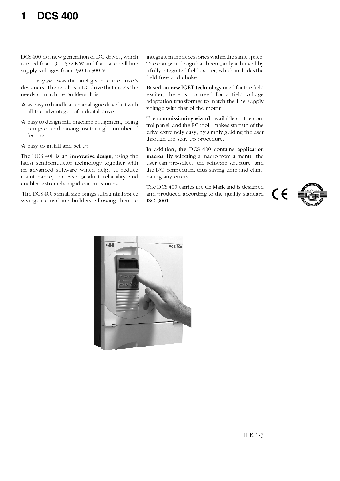
1 DCS 400 - the compact-size DC drive
DCS 400 is a new generation of DC drives, which
is rated from 9 to 522 KW and for use on all line
supply voltages from 230 to 500 V.
Total ease of use
designers. The result is a DC drive that meets the
needs of machine builders. It is:
I
as easy to handle as an analogue drive but with
all the advantages of a digital drive
I
easy to design into machine equipment, being
compact and having just the right number of
features
I
easy to install and set up
The DCS 400 is an
latest semiconductor technology together with
an advanced software which helps to reduce
maintenance, increase product reliability and
enables extremely rapid commissioning.
The DCS 400's small size brings substantial space
savings to machine builders, allowing them to
was the brief given to the drive`s
innovative design
, using the
integrate more accessories within the same space.
The compact design has been partly achieved by
a fully integrated field exciter, which includes the
field fuse and choke.
Based on
exciter, there is no need for a field voltage
adaptation transformer to match the line supply
voltage with that of the motor.
The
trol panel and the PC tool - makes start up of the
drive extremely easy, by simply guiding the user
through the start up procedure.
In addition, the DCS 400 contains
macros
user can pre-select the software structure and
the I/O connection, thus saving time and elimi-
nating any errors.
The DCS 400 carries the CE Mark and is designed
and produced according to the quality standard
ISO 9001.
new IGBT technology
commissioning wizard
. By selecting a macro from a menu, the
used for the field
-available on the con-
application
II K 1-3

DCS 400 - the compact-size DC drive
Unit functions
Drive functions
Speed ramp function generator (S-ramp,
2 accel / decel ramps)
Speed feedback via tacho, encoder, EMF
Speed controlling
Torque / current reference processing
External torque limitation
Current controlling
Automatic field weakening
Automatic optimization for armature-circuit
current, field current, speed controller, EMF
regulator, flux adaptation
Speed monitor
On/Off control logic
Remote/local operation
Emergency stop
Automatic phase sequence detection
Motor overload detection
Internal motor potentiometer function for the
speed reference
Jog function
Configuration macros
Activation and operator-control
analogue and digital
fieldbusses
MMC
(man-machine communication) via:
Drive Window Light
(start-up and maintenance program) PC pro-
grams can be run under all commonly used
Windows® environments (3.1x, 95,98, NT):
Parameter programming
Fault detection
Feedback display and analysis
Fault logger
DCS400PAN
Removable control and display panel with
plain text display for:
Guided
Parameter programming
Fault detection
Reference and feedback display
Local operation
commissioning
inputs
and
outputs
Monitoring functions
Self-test
Fault logger
Motor monitoring
Speed feedback error
Overtemperature (PTC evaluation)
Overload (I² t)
Overspeed
Stalled motor
Armature-circuit overcurrent
Armature-circuit overvoltage
Minimum field current
Field overcurrent
Power converter protection
Overtemperature
Watchdog function
Mains voltage interruption
Thyristor diagnosis
II K 1-4

2 System overview of DCS 400
)LHOGVXSSO\
6'&6),6$
M
U
H
W
O
L
I
&
0
(
F1
Q1
115 / 230 V AC
L1
K1
0
/HJHQG
Q
R
L
W
D
O
R
V
L
F
L
Q
D
Y
O
Q
D
J
J
Q
L
$
J
V
R
L
Q
V
W
L
&
W
9
E
L
$
E
9
W
W
X
X
W
S
S
X
W
W
W
S
X
X
X
Q
R
R
L
S
W
H
H
X
Q
X
X
L
R
J
J
O
\
R
D
R
O
O
W
D
L
O
D
D
J
H
Q
Q
L
5
D
$
G
230...500V
115...230 V AC
1
U
R
&
O
/
&
R
3
R
3
7
Fig. 2/1: System overview of DCS 400
RS232
T
$
U
1
,
H
3
Z
R
6
3
&
'
6
V
F
L
$
Q
R
U
1
W
F
2
H
O
&
H
6
O
'&6
R
&
U
W
'
Q
6
R
&
U
1
$
3
6
&
'
O
R
W
R
U
V
W
L
U
Q
\
R
K
F
7
6HULDO
LQWHUIDFHV
\
O
S
S
X
6
O
H
Q
D
S
O
R
U
W
Q
R
&
O
R
G
U
O
W
H
L
Q
R
)
F
V
W
X
S
W
X
2
V
P
W
X
µ
S
Q
,
2
82
4
optical fibre
[
[
[
[
1
T
&
V
/
X
3
E
H
G
O
K
H
W
L
R
)
W
II K 2-1
2.1 Environmental conditions
System overview of DCS 400
Mains supply - power part
Voltage, 3-phase: 230 to 500 V in acc. with IEC 38
Voltage deviation: ±10% permanent
Rated frequency: 50 Hz or 60 Hz
Static frequency deviation: 50 Hz ±2 %; 60 Hz ±2 %
Dynamic: frequency range: 50 Hz: ±5 Hz; 60 Hz: ± 5 Hz
df/dt: 17 % / s
Mains supply - Electronics supply
Voltage, 1-phase: 115 to 230 V in acc. with IEC 38
Voltage deviation: -15% / +10%
Frequency range: 45 Hz to 65 Hz
Degree of protection
Power converter module: IP 00
Paint finish
Power converter module, cover: RAL 9002 light-grey
housing: RAL 7012 dark-grey
Current reduction to (%) for armature circuit and field supply
100
90
80
70
60
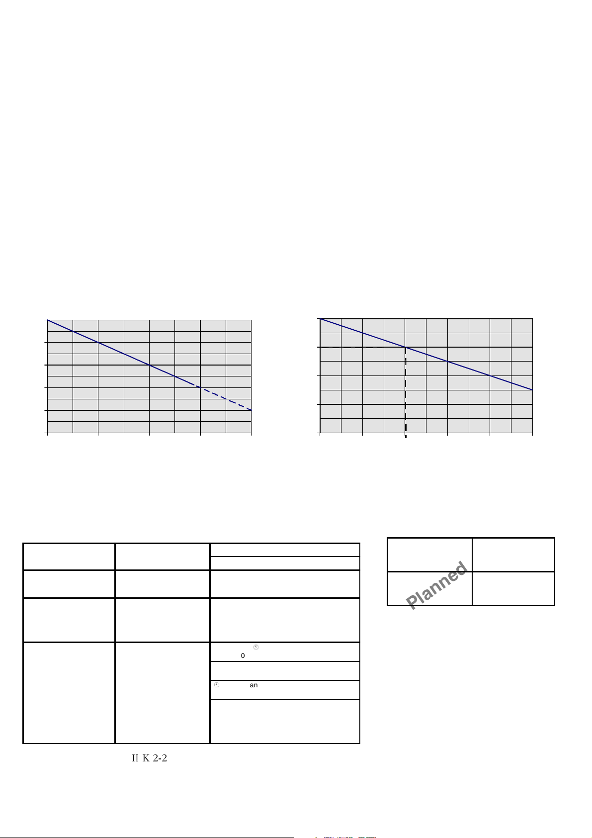
Environmental limit values
Permissible ambient temp. with rated current I
Ambient temp., power conv. module:+40°C to 55°C; s. Fig. 2.1/2
: +5 to +40°C
DC
Alteration in the ambient temp.: < 0,5°C / minute
Storage temperature: -40 to +55°C
Transport temperature: -40 to +70°C
Relative humidity: 5 to 95%, no condensation
Pollution degree: Grade 2
Site elevation:
<1000 m above M.S.L.: 100%, without current reduction
>1000 m above M.S.L.: with current reduct., s. Fig. 2.1/1
Vibration converter module: 0,5 g; 5 Hz to 55 Hz
Noises: Size as module
(1 m distance)
A1 55 dBA
A2 55 dBA
A3 60 dBA
A4 66...70 dBA, dependent on fan
Current reduction to (%) for armature circuit and field supply
110
100
90
80
50
1000 2000 3000 4000 5000
Fig. 2.1/1: Effect of the site elevation above sea level on the
power converter's load capacity
m
70
30 35 40 45 50 55
Fig. 2.1/2: Effect of the ambient temperature on the converter
module load capacity.
Compliance with standards
The power converter modules and cubicles are designed for industrial applications.
Within the EU, the components satisfy the requirements European guidelines, shown
in the table below.
European Union Directive Manufacturer’s Assurance
Machinery Directive
89/392/EEC
93/68/EEC
Low Voltage Directive
73/23/EEC
93/68/EEC
EMC Directive
89/336/EEC
93/68/EEC
Declaration of
Incorporation
Declaration of Conformity
Declaration of Conformity.
Provided that all installation
instructions concerning
cable selection, cabling and
EMC filters or dedicated
transformer are followed.
EN 60204-1
[IEC 204-1]
EN 60146-1-1
[IEC 146-1-1]
EN 50178 [IEC --]
see additional
IEC 664
EN 61800-3
[IEC 1800-3]
where limits are under consideration
EN 50081-2 / EN 50082-2 has been supplied
¥
’Installation in accordance with EMC’
The Technical Construction File to which this
Declaration relates has been assessed by
Report and Certificate from ABB EMC
Certification AB being the Competent Body
according to the EMC Directive.
Harmonized Standards
Converter module
¥
in accordance with 3ADW 000 032
under preparation
°C
Standards in North America
In North America, the system components
satisfy the requirements as listed in the
table below.
Safety for Power
conversion Equipment
≤ 600 V
Industrial control
Equipment: industrial
products ≤ 600 V
Standard for module
UL 508 C
CSA C 22.2. No.1495
Planned for 2000
Please note:
applies for power converter modules only.
II K 2-2
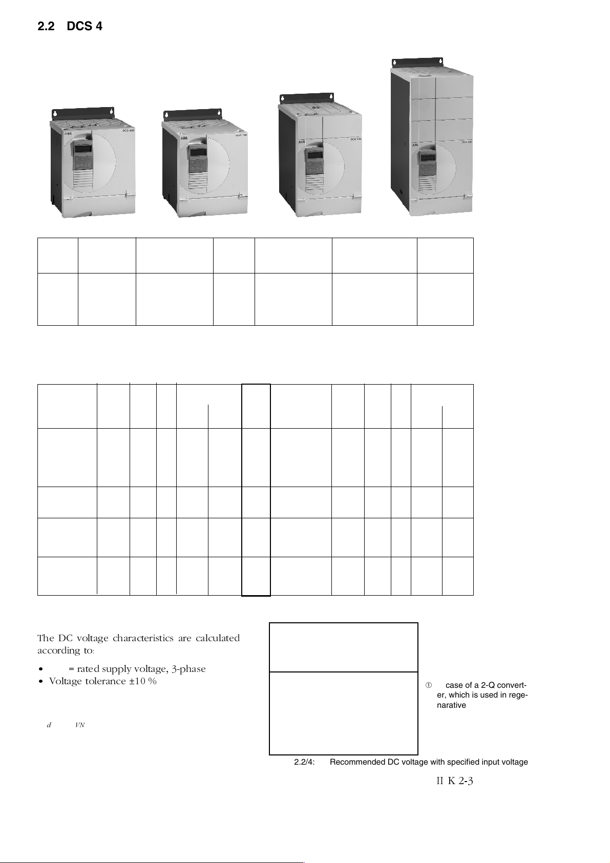
2.2 DCS 400 power converter modules
Sizes
System overview DCS 400
Size A1
Size Current Dimensions Weight Min. Clearances Fan connection Fuses
range H x W x D appr. top/butom/side
A1 20...25 A 310x270x200 11 150x100x5 - external
A1 45...140 A 310x270x200 11 150x100x5 115/230 V/1 ph external
A2 180...260 A 310x270x270 16 250x150x5 115/230 V/1 ph external
A3 315...550 A 400x270x310 25 250x150x10 115/230 V/1 ph external
A4 610...1000 A 580x270x345 38 250x150x10 ➀ 230 V/1 ph external
Table 2.2/1: Sizes of DCS 400
Size A2
[mm] [kg] [mm]
Size A3
Size A4
➀ Fan with 115 V/1 ph
available as option
Unit table
DCS 401 2-quadrant converter DCS 402 4-quadrant converter
Converter type Line voltage
I
[A] I
DC
DCS401.0020 20 16 4 9 12
DCS401.0045 45 36 6 21 26
DCS401.0065 65 52 6 31 39
DCS401.0090 90 74 6 41 52
DCS401.0125 125 102 6 58 73
DCS401.0180 180 147 16 84 104
DCS401.0230 230 188 16 107 133
[A] IF [A] P [kW] P [kW]
AC
400 V 500 V
Converter type Line voltage
Size
I
[A] I
DC
DCS402.0025 25 20 4 10 13
A1
DCS402.0050 50 41 6 21 26
A1
DCS402.0075 75 61 6 31 39
A1
DCS402.0100 100 82 6 41 52
A1
DCS402.0140 140 114 6 58 73
A1
DCS402.0200 200 163 16 83 104
A2
DCS402.0260 260 212 16 108 135
A2
[A] IF [A] P [kW] P [kW]
AC
400 V 500 V
DCS401.0315 315 257 16 146 183
DCS401.0405 405 330 16 188 235
DCS401.0500 500 408 16 232 290
DCS401.0610 610 498 20 284 354
DCS401.0740 740 604 20 344 429
DCS401.0900 900 735 20 419 522
Table 2.2/2: DCS 401 unit table
DC voltage characteristic
The DC voltage characteristics are calculated
according to:
U
= rated supply voltage, 3-phase
VN
Voltage tolerance ±10 %
()
88
91G
cos a = 0.966 (2-Q)
0.866 (4-Q)
α
cos*35.1*%10−=
DCS402.0350 350 286 16 145 182
A3
DCS402.0450 450 367 16 187 234
A3
DCS402.0550 550 448 16 232 290
A3
DCS402.0680 680 555 20 282 354
A4
DCS402.0820 820 669 20 340 426
A4
DCS402.1000 1000 816 20 415 520
A4
Table 2.2/3: DCS 402 unit table
System con- DC voltage
nection voltage (max. Motor voltage)
U
vN
230 270 240
380 460 400
400 470 420
415 490 430
440 520 460
460 540 480
480 570 500
500 600 520
Table 2.2/4: Recommended DC voltage with specified input voltage
2Q ➀ 4Q
U
d
➀ in case of a 2-Q convert-
er, which is used in regenarative mode, please
use 4-Q voltage values
II K 2-3
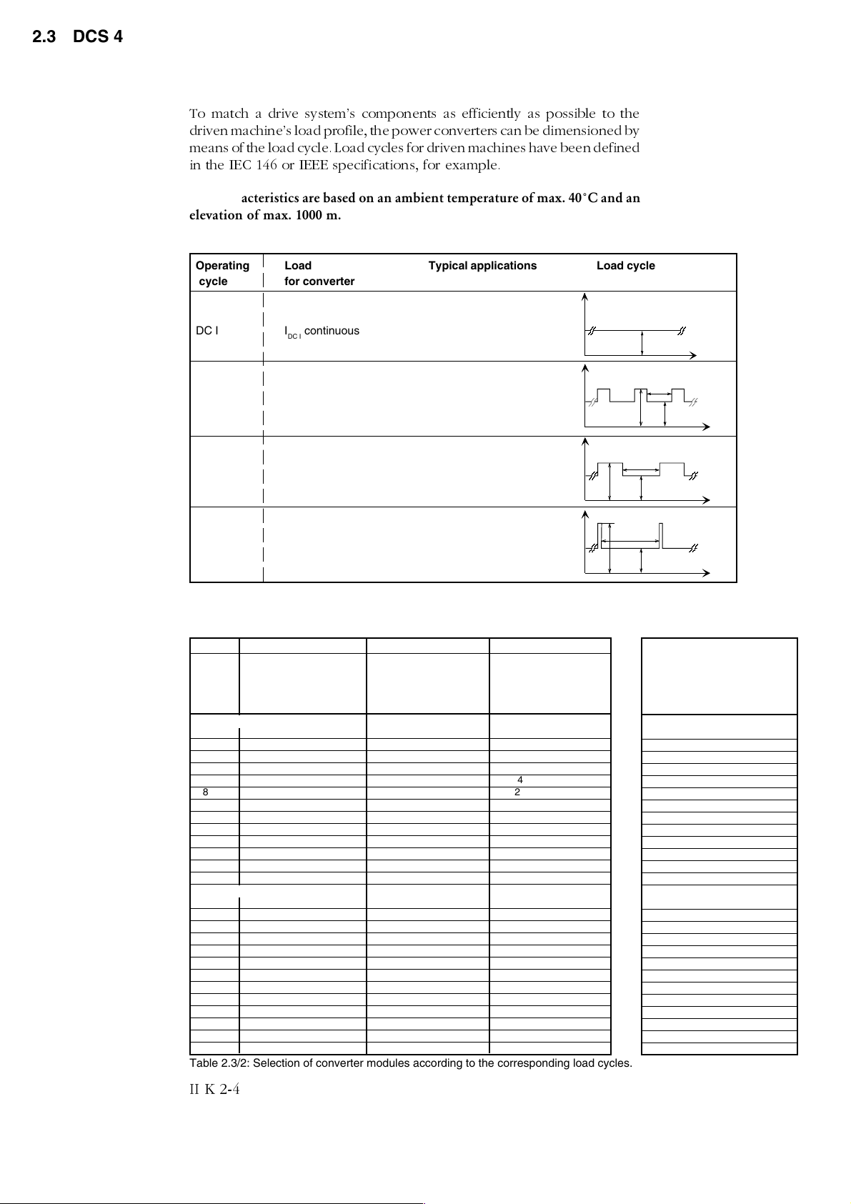
2.3 DCS 400 overload withstand capability
To match a drive systems components as efficiently as possible to the
driven machines load profile, the power converters can be dimensioned by
means of the load cycle. Load cycles for driven machines have been defined
in the IEC 146 or IEEE specifications, for example.
The characteristics are based on an ambient temperature of max. 40°C and an
elevation of max. 1000 m.
Types of load
Operating Load Typical applications Load cycle
cycle for converter
System overview of DCS 400
DC I I
DC II I
DC III I
DC IV I
continuous (IdN) pumps, fans
DC I
for 15 min and extruders, conveyor belts
DC II
1,5 * I
DC III
1,5 * I
DC IV
2 * I
for 60 s
DC II
for 15 min and extruders, conveyor belts
for 120 s
DC III
for 15 min and
for 10 s
DC IV
150%
150%
200%
Table 2.3/1: Definition of the load cycles
Load cycles of driven machines
DC I DC II DC III DC IV
I
DC I
contin- 100 % 150 % 100 % 150 % 100 % 200 %
uous 15 min 60 s 15 min 120 s 15 min 10 s
[A] [A] [A] [A]
2-quadrant applications
20 18 27 18 27 18 36
45 40 60 37 56 38 76
65 54 81 52 78 55 110
90 78 117 72 108 66 132
125 104 156 100 150 94 188
180 148 222 144 216 124 248
230 200 300 188 282 178 356
315 264 396 250 375 230 460
405 320 480 310 465 308 616
500 404 606 388 582 350 700
610 490 735 482 723 454 908
740 596 894 578 867 538 1076
900 700 1050 670 1005 620 1240
4-quadrant applications
25 23 35 22 33 21 42
50 45 68 43 65 38 76
75 66 99 64 96 57 114
100 78 117 75 113 67 134
140 110 165 105 158 99 198
200 152 228 148 222 126 252
260 214 321 206 309 184 368
350 286 429 276 414 265 530
450 360 540 346 519 315 630
550 436 654 418 627 380 760
680 544 816 538 807 492 984
820 664 996 648 972 598 1196
1000 766 1149 736 1104 675 1350
Table 2.3/2: Selection of converter modules according to the corresponding load cycles.
I
DC II
I
DC III
I
DC IV
ð
100%
15 min
100%
15 min
100%
15 min
100%
Recommended
Converter type
Converter type
2-quadrant converter
DCS 401.0020
DCS 401.0045
DCS 401.0065
DCS 401.0090
DCS 401.0125
DCS 401.0180
DCS 401.0230
DCS 401.0315
DCS 401.0405
DCS 401.0500
DCS 401.0610
DCS 401.0740
DCS 401.0900
4-quadrant converter
DCS 402.0025
DCS 402.0050
DCS 402.0075
DCS 402.0100
DCS 402.0140
DCS 402.0200
DCS 402.0260
DCS 402.0350
DCS 402.0450
DCS 402.0550
DCS 402.0680
DCS 402.0820
DCS 402.1000
II K 2-4

2.4 Control and Display Units of the DCS 400
System overview DCS 400
For operation, commissioning, diagnosis and for
controlling the drive, there are different possibil-
ities available.
'&63$1
Panel
connection
3&
Fig. 2.4/1: Possibilities of operation
6'&6&21$
X7:
electrical
connection
(RS232)
The coupling to an overriding system (PLC) takes
place over a serial interface with a fibre-optic link
to a field bus adapter.
'&6
X6:
V800
X8:
power supply
PE SHF DG D( N) D(P)SH
X2
optical fibre
10 m
≤
RXD
Nxxx-01
TXD
xxxxxxxx
ADAPTER
XMIT
BUS
TERMINA TION
REC
ERROR
X1
PE SHF DG D( N) D(P)
+24V 0V SH
)LHOGEXV
$GDSWHU
ON
OFF
WR3/&
440V 368A 1500rpm
1500rpm
OUTPUT MENU AUTO OFF LOC <RUN>
Panel DCS 400 PAN
Features
Guided commissioning
(Panel Wizard)
Drive control
Parameter programming
Display of reference and ac-
tual values
Status information
Fault reset
Multilingual
removable during operation
7-Segment display
Features
RAM/ROM memory test error
Program is not running
Normal situation
During download sequence
Alarm
Fault
Fieldbus Adapter
Components:
plastic optical fibre
field bus adaptor
available Fieldbus adapters:
PROFIBUS
AC 31
MODBUS
MODBUS+
CAN-BUS
DeviceNet
You will find more detailed information on data
exchange in the related documentation for field
bus adapters.
II K 2-5
System overview of DCS 400
Operation by PC
Components :
RS232 standard cable, 9-pin sub-D connector,
male-female, non-crossing
Functionality:
Software package "Drive Window Light"
System requirements/recommendation:
PC with 386 processor or higher
hard disk with 5 MB free memory
VGA monitor
Windows 3.1, 3.11, 95, 98, NT
3 1/2" floppy disk drive
CAUTION!
To avoid unintentional operating states, or to shut
the unit down in case of any imminent danger
according to the standards in the safety instructions it is not sufficient to merely shut down the
drive via signals 'RUN', drive 'OFF' or 'Emergency
Stop' respectively 'control panel' or 'PC tool'.
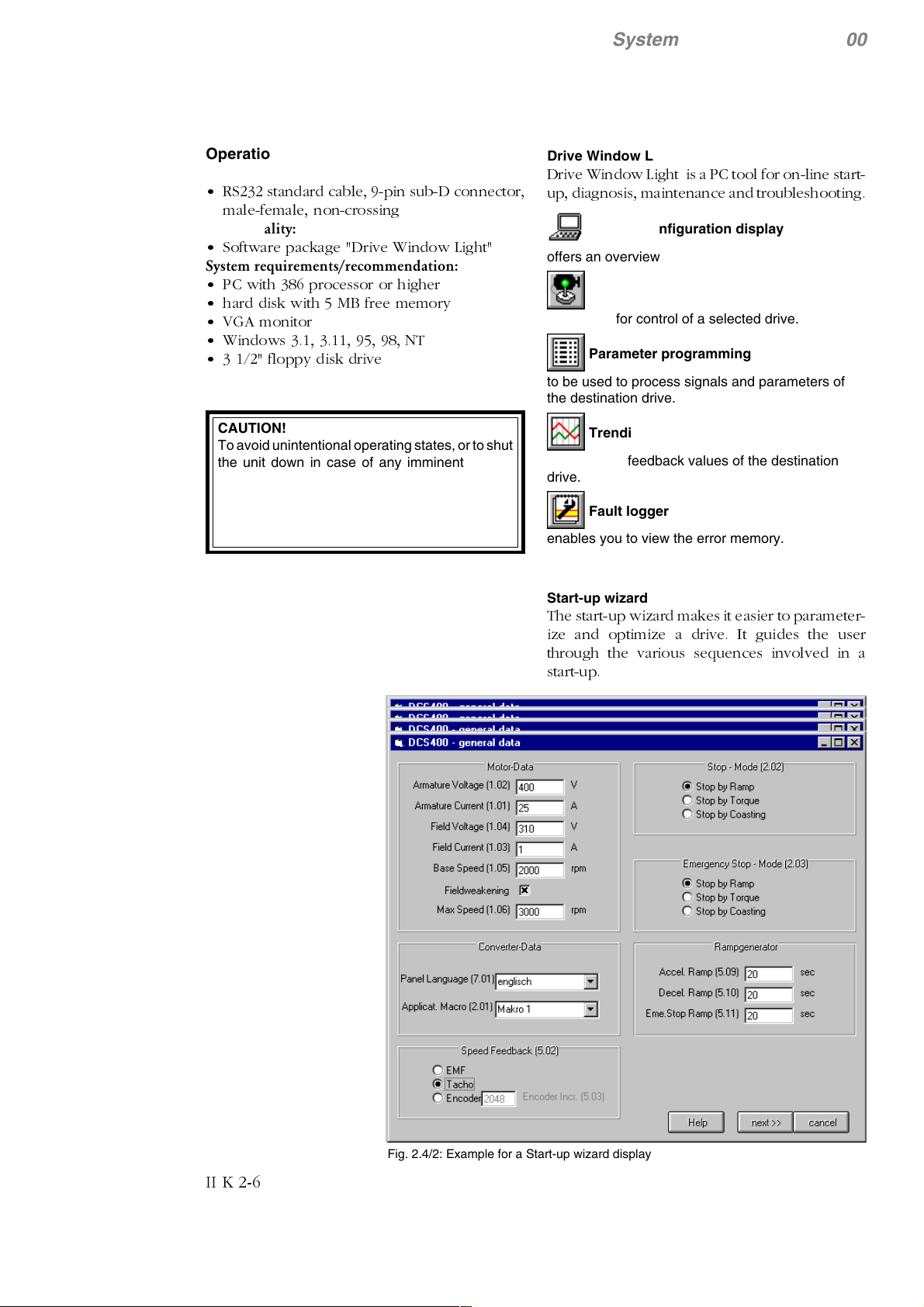
Drive Window Light
Drive Window Light is a PC tool for on-line start-
up, diagnosis, maintenance and troubleshooting.
System configuration display
offers an overview the system.
Drive control
to be used for control of a selected drive.
Parameter programming
to be used to process signals and parameters of
the destination drive.
Trending
monitors the feedback values of the destination
drive.
Fault logger
enables you to view the error memory.
Start-up wizard
The start-up wizard makes it easier to parameter-
ize and optimize a drive. It guides the user
through the various sequences involved in a
start-up.
II K 2-6
Fig. 2.4/2: Example for a Start-up wizard display

3 Technical Data
3.1 Module dimensions
Module A1
DCS 401.0020
DCS 401.0045
DCS 401.0065
DCS 401.0090
DCS 401.0125
DCS 402.0025
DCS 402.0050
DCS 402.0075
DCS 402.0100
DCS 402.0140
Module A2
DCS 401.0180
DCS 401.0230
DCS 402.0200
DCS 402.0260
Technical data
Module A3
DCS 401.0315
DCS 401.0405
DCS 401.0500
DCS 402.0350
DCS 402.0450
DCS 402.0550
Dimensions in mm
Fig. 3.1/1: Dimension drawing A1, A2, A3-Module
II K 3-1

Module A4
DCS 401.0610
DCS 401.0740
DCS 401.0900
DCS 402.0680
DCS 402.0820
DCS 402.1000
Dimensions in mm
Technical data
for M6
for M12
II K 3-2
Fig. 3.1/2: Dimension drawing A4-Module
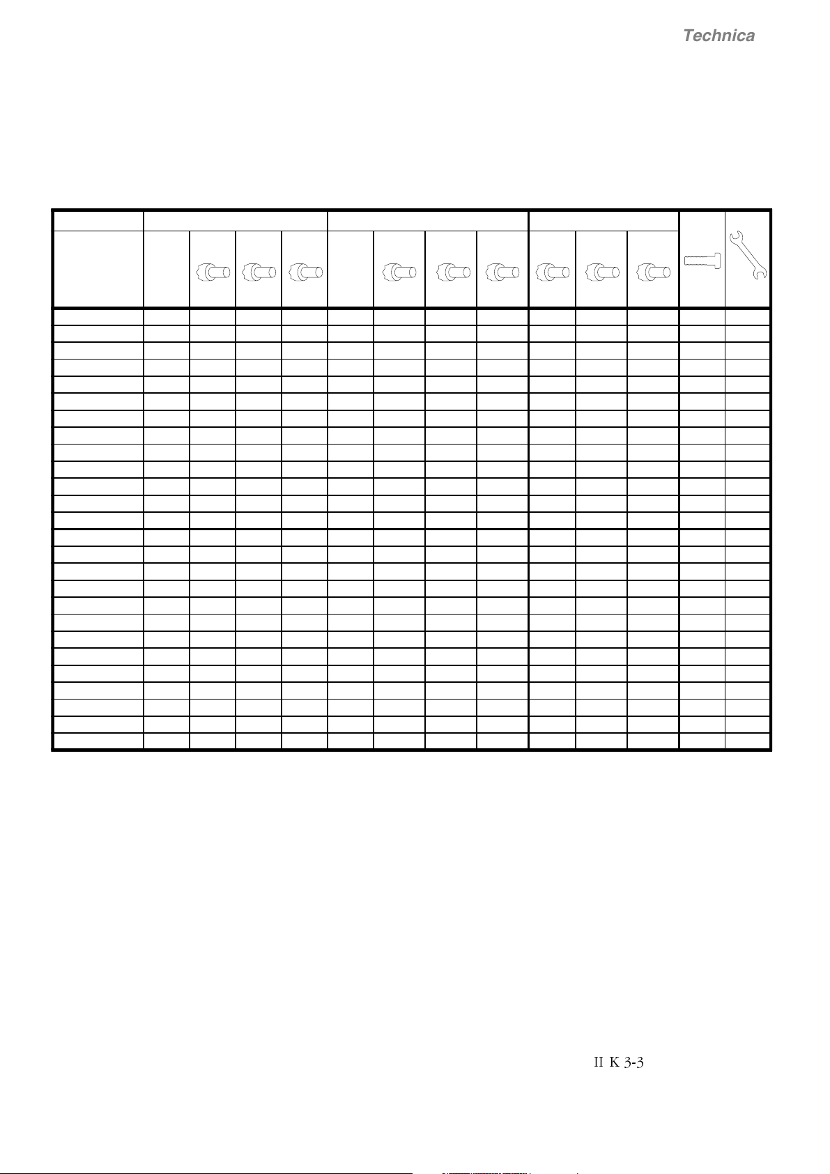
3.2 Cross-sectional areas - Tightening torques
Technical data
3.2.1 Recommended cross-sectional area to DIN VDE 0276-1000 and DIN VDE 0100-540 (PE), trefoil arrangement, up to 40°C
ambient temperature and a 90°C operating temperature of the conductor.
Unit type
IDC
[A-]
DCS 401.0020 20 1 x 2.5 1 x 1.5 1 x 1.5 16 1 x 2.5 1 x 1.5 1 x 1.5 1 x 2.5 1 x 1.5 1 x 1.5 M6 6
DCS 401.0045 45 1 x 10 1 x 6 1 x 6 36 1 x 6 1 x 6 1 x 4 1 x 6 1 x 6 1 x 4 M6 6
DCS 401.0065 65 1 x 16 1 x 10 1 x 10 52 1 x 16 1 x 10 1 x 6 1 x 16 1 x 10 1 x 6 M6 6
DCS 401.0090 90 1 x 25 1 x 16 1 x 16 74 1 x 25 1 x 16 1 x 16 1 x 16 1 x 16 1 x 16 M6 6
DCS 401.0125 125 1 x 35 1 x 25 1 x 25 102 1 x 35 1 x 25 1 x 25 1 x 16 1 x 16 1 x 16 M6 6
DCS 401.0180 180 1 x 70 1 x 50 1 x 50 147 1 x 50 1 x 50 1 x 35 1 x 25 1 x 25 1 x 16 M10 25
DCS 401.0230 230 1 x 95 1 x 70 1 x 70 188 1 x 70 1 x 70 1 x 50 1 x 35 1 x 35 1 x 25 M10 25
DCS 401.0315 315 2 x 50 1 x 95 1 x 120 257 2 x 50 1 x 95 1 x 95 1 x 50 1 x 50 1 x 50 M10 25
DCS 401.0405 405 2 x 70 2 x 50 1 x 150 330 2 x 70 2 x 50 1 x 120 1 x 70 1 x 50 1 x 70 M10 25
DCS 401.0500 500 2 x 120 2 x 70 2 x 70 408 2 x 95 2 x 70 2 x 70 1 x 95 1 x 70 1 x 70 M10 25
DCS 401.0610 * 610 2 x 150 2 x 95 2 x 95 498 2 x 150 2 x 95 2 x 70 1 x 150 1 x 95 1 x 70 M12 50
DCS 401.0740 * 740 2 x 240 2 x 150 2 x 150 604 2 x 185 2 x 120 2 x 95 1 x 185 1 x 120 1 x 95 M12 50
DCS 401.0900 * 900 2 x 240 2 x 185 2 x 185 735 2 x 240 2 x 150 2 x 150 1 x 240 1 x 150 1 x 150 M12 50
DCS 402.0025 25 1 x 2.5 1 x 2.5 1 x 2.5 20 1 x 2.5 1 x 2.5 1 x 1.5 1 x 2.5 1 x 2.5 1 x 1.5 M6 6
DCS 402.0050 50 1 x 10 1 x 6 1 x 6 41 1 x 10 1 x 6 1 x 4 1 x 10 1 x 6 1 x 4 M6 6
DCS 402.0075 75 1 x 16 1 x 10 1 x 16 61 1 x 16 1 x 10 1 x 10 1 x 16 1 x 10 1 x 10 M6 6
DCS 402.0100 100 1 x 25 1 x 16 1 x 25 82 1 x 25 1 x 16 1 x 16 1 x 16 1 x 16 1 x 16 M6 6
DCS 402.0140 140 1 x 50 1 x 35 1 x 35 114 1 x 35 1 x 25 1 x 25 1 x 16 1 x 16 1 x 16 M6 6
DCS 402.0200 200 1 x 70 1 x 50 1 x 70 163 1 x 70 1 x 50 1 x 50 1 x 35 1 x 25 1 x 25 M10 25
DCS 402.0260 260 1 x 120 1 x 70 1 x 95 212 1 x 95 1 x 70 1 x 70 1 x 50 1 x 35 1 x 35 M10 25
DCS 402.0350 350 2 x 70 1 x 120 1 x 120 286 2 x 50 1 x 120 1 x 95 1 x 50 1 x 70 1 x 50 M10 25
DCS 402.0450 450 2 x 95 2 x 70 2 x 70 367 2 x 70 2 x 70 2 x 50 1 x 70 1 x 70 1 x 50 M10 25
DCS 402.0550 550 2 x 120 2 x 95 2 x 95 465 2 x 120 2 x 70 2 x 70 1 x 120 1 x 70 1 x 70 M10 25
DCS 402.0680 * 680 2 x 185 2 x 120 2 x 120 555 2 x 150 2 x 120 2 x 95 1 x 150 1 x 120 1 x 95 M12 50
DCS 402.0820 * 820 2 x 240 2 x 150 2 x 150 669 2 x 240 2 x 150 2 x 120 1 x 240 1 x 150 1 x 120 M12 50
DCS 401.1000 * 1000 2 x 300 2 x 185 2 x 185 816 2 x 240 2 x 150 2 x 150 1 x 240 1 x 150 1 x 150 M12 50
* Busbar connection 5 x 40 mm is recommended
C1, D1 U1, V1, W1 PE
HO7V
[mm²]
NSGA
FÖU
[mm²]
N2XY
[mm²]Iv[A~]
HO7V
[mm²]
NSGA
FÖU
[mm²]
N2XY
[mm²]
HO7V
[mm²]
NSGA
FÖU
[mm²]
❶
N2XY
[mm²]
1 x M.. [Nm]
Table 3.2/1: Cross-sectional areas - tightening torques DCS 400
❶
You will find instructions on how to calculate the PE
conductor’s cross-sectional area in VDE 0100 or in
equivalent national standards. We would remind you
that power converters may have a current-limiting
effect. This can lead to other values than recommended.
Definition of the recommended cables above:
H07V: DIN-VDE 0281-1; Polyvinyl chloride insulated cables
NSGAFÖU: DIN-VDE 0250-602; Special rubber-insulated single-core cables
N2XY: DIN-VDE 0276-604; Power cable with special fire performance
II K 3-3

3.2.2 Cross-sectional areas for UL installations
• The DCS 400 should be installed in an enclosure
that is minimum 150% of the dimensions of converter.
• The DCS 400 is suitable for use in a circuit capable
of delivering not more than 18 kA rms Symetrical
amperes, 500 V AC maximum. Recommended
fuses must be used to provide short circuit protection.
Technical data
Unit type
DCS 401.0020 20 1 x 10 16 1 x 14 12 M6 6
DCS 401.0045 45 1 x 4 36 1 x 6 10 M6 6
DCS 401.0065 65 1 x 3 52 1 x 4 8 M6 6
DCS 401.0090 90 1 x 1/0 74 1 x 2 8 M6 6
DCS 401.0125 125 1 x 2/0 102 1 x 2/0 6 M6 6
DCS 401.0180 180 1 x 4/0 147 1 x 4/0 6 M10 25
DCS 401.0230 230 1 x 350 188 1 x 300 4 M10 25
DCS 401.0315 315 2 x 3/0 257 2 x 3/0 3 M10 25
DCS 401.0405 405 2 x 250 330 2 x 250 2 M10 25
DCS 401.0500 500 2 x 400 408 2 x 350 2 M10 25
DCS 401.0610 610 * 498 * 0 M12 50
DCS 401.0740 740 *604* 0M1250
DCS 401.0900 900 * 735 * ??? M12 50
DCS 402.0025 25 1 x 8 20 1 x 12 10 M6 6
DCS 402.0050 50 1 x 4 41 1 x 6 10 M6 6
DCS 402.0075 75 1 x 2 61 1 x 3 10 M6 6
DCS 402.0100 100 1 x 1/0 82 1 x 1 8 M6 6
DCS 402.0140 140 1 x 2/0 114 1 x 2/0 6 M6 6
DCS 402.0200 200 1 x 250 163 1 x 250 6 M10 25
DCS 402.0260 260 2 x 2/0 212 1 x 400 4 M10 25
DCS 402.0350 350 2 x 4/0 286 2 x 4/0 3 M10 25
DCS 402.0450 450 2 x 300 367 2 x 300 2 M10 25
DCS 402.0550 550 2 x 500 465 2 x 400 1 M10 25
DCS 402.0680 680 *555* 0M1250
DCS 402.0820 820 * 669 * 2/0 M12 50
DCS 401.1000 1000 * 816 * ??? M12 50
* Busbar connection 5 x 40 mm required
C1, D1 U1, V1, W1 PE
IDC
[A-]
Wire
size
[AWG or
MCM]Iv[A~]
Wire
size
[AWG]
Under preparation
Under preparation
Wire
size
[AWG]
1 x M.. [Nm]
Note: 60°C wire up to 100 A, 75°C wire over 100 A
Note: Use UL listed ring terminals for connections to drives
Table 3.2/2: Cross-sectional areas for UL installations of DCS 400
II K 3-4
3.3 Power losses
DCS 400 armature circuit
Technical data
Converter type Power losses PL [W]
Load
I
[A] 25% 50% 75% 100%
DC
DCS401.0020 20 10 22 35 49
DCS401.0045 45 25 57 95 145
DCS401.0065 65 38 80 128 181
DCS401.0090 90 48 103 166 236
DCS401.0125 125 65 138 220 311
DCS401.0180 180 96 210 341 490
DCS401.0230 230 116 254 413 594
DCS401.0315 315 163 339 526 726
DCS401.0405 405 218 444 697 969
DCS401.0500 500 236 513 830 1188
2-Quadrant4-Quadrant
DCS401.0610 610 312 653 1025 1427
DCS401.0740 740 380 799 1259 1758
DCS401.0900 900 467 993 1578 2222
DCS402.0025 25 13 28 46 65
DCS402.0050 50 28 65 109 162
DCS402.0075 75 44 95 152 217
DCS402.0100 100 53 116 188 270
DCS402.0140 140 73 157 252 357
DCS402.0200 200 108 238 389 562
DCS402.0260 260 133 293 481 696
DCS402.0350 350 182 265 591 818
DCS402.0450 450 237 499 785 1096
DCS402.0550 550 262 573 933 1342
DCS402.0680 680 349 736 1160 1622
DCS402.0820 820 423 895 1416 1986
DCS402.1000 1000 522 1116 1786 2527
Table 3.3/1: DCS 400 Power losses of armature circuit
Remarks on the table
• The values stated are are maximum values obtained under the most unfavourable conditions.
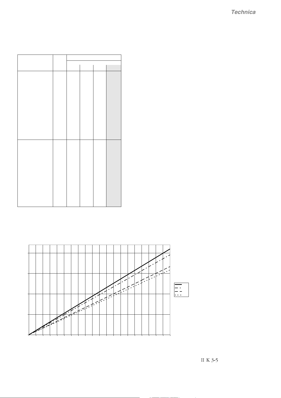
DCS 400 field supply
P
L
200
[W]
150
100
50
0
01234567891011121314151617181920
Fig. 3.3/1: DCS 400 Power losses of field supply
[A]
440V
350V
150V
50V
I
II K 3-5
3.4 Power section cooling
Technical data
Fan assignment for DCS 400
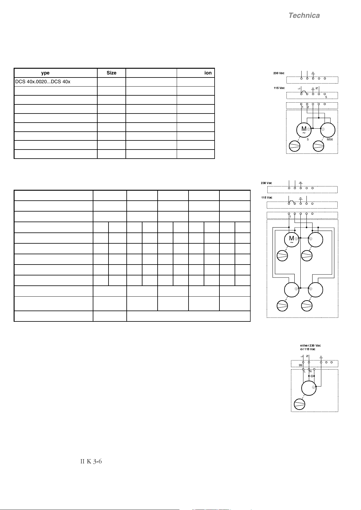
Converter type Size Fan type Configuration
DCS 40x.0020...DCS 40x.0025 A1 no Fan -
DCS 40x.0045...DCS 40x.0140 A1 2x CN2B2 1
DCS 40x.0180...DCS 40x.0260 A2 2x CN2B2 1
DCS 40x.0315...DCS 40x.0350 A3 2x CN2B2 1
DCS 40x.0405...DCS 40x.0550 A3 4x CN2B2 2
DCS 40x.0610...DCS 40x.0820 A4 1x W2E200 (230 V) 3
DCS 40x.0610. 2...DCS 40x.0820. 2 A4 1x W2E200 (115 V) 3
DCS 40x.0900...DCS 40x.1000 A4 1x W2E250 (230 V) 3
DCS 40x.0900. 2...DCS 40x.1000. 2 A4 1x W2E250 (115 V) 3
Table 3.4/1: Fan assignment for DCS 400
Fan data for DCS 400 (data per fan)
Fan type
Rated voltage [V] 115; 1~ 230; 1~ 115; 1~ 115; 1~ 230; 1~
Tolerance [%] ±10 +6/-10 +6/-10 ±10 +6/-10
Frequency [Hz] 50 60 50 60 50 60 50 60 50 60
CN2B2 W2E200 W2E200 W2E250 W2E250
Fan connection for DCS 400
L
9DF
9DF
N
12 3X99: 45
L
N
12 3X99: 45
12 3X99:
45
M
~
M55 M5 6
M
Configuration 1
L
9DF
9DF
N
12 3X99: 45
L
N
12 3X99: 45
12 3X99:
45
~
Power consuption [W] 16 13 64 80 64 80 120 165 135 185
Current consumption [A] 0.2 0.17 0.29 0.35 0.6 0.7 1.06 1.44 0.59 0.82
Stall current [A] < 0.3 < 0.26 < 0.7 < 0.8 <1.5 <1.8 <1.8 <1.8 <0.9 <0.9
3
Air volume, freely blowing [m
/h] 156 180 925 1030 925 1030 1835 1940 1860 1975
Noise levelt [dBA] 44 48 59 61 59 61 66 67 68 70
Max. ambient temperature [° C] < 60 < 75 < 75 60 60
Useful lifetime of fan
appr. 40000
h/60°
appr. 45000
h/60°
appr. 45000
h/60°
appr. 40000 h appr. 40000 h
Protection Stall Overtemperature
Table 3.4/2: Fan data for DCS 400
Monitoring the DCS 400 power section
The power sections are monitored by an electrically
isolated PTC thermistor detector. First an alarm will
be outputted, and - if the temperature continues to
rise - an error message. This will switch off the unit
in a controlled manner.
M
~
M55 M5 6
M
~
M57 M5 8
M
M
~
~
Configuration 2
HLWKHU9DF
RU9DF
L
N
12 345X99:
LN
M
~
M55
II K 3-6
Configuration 3
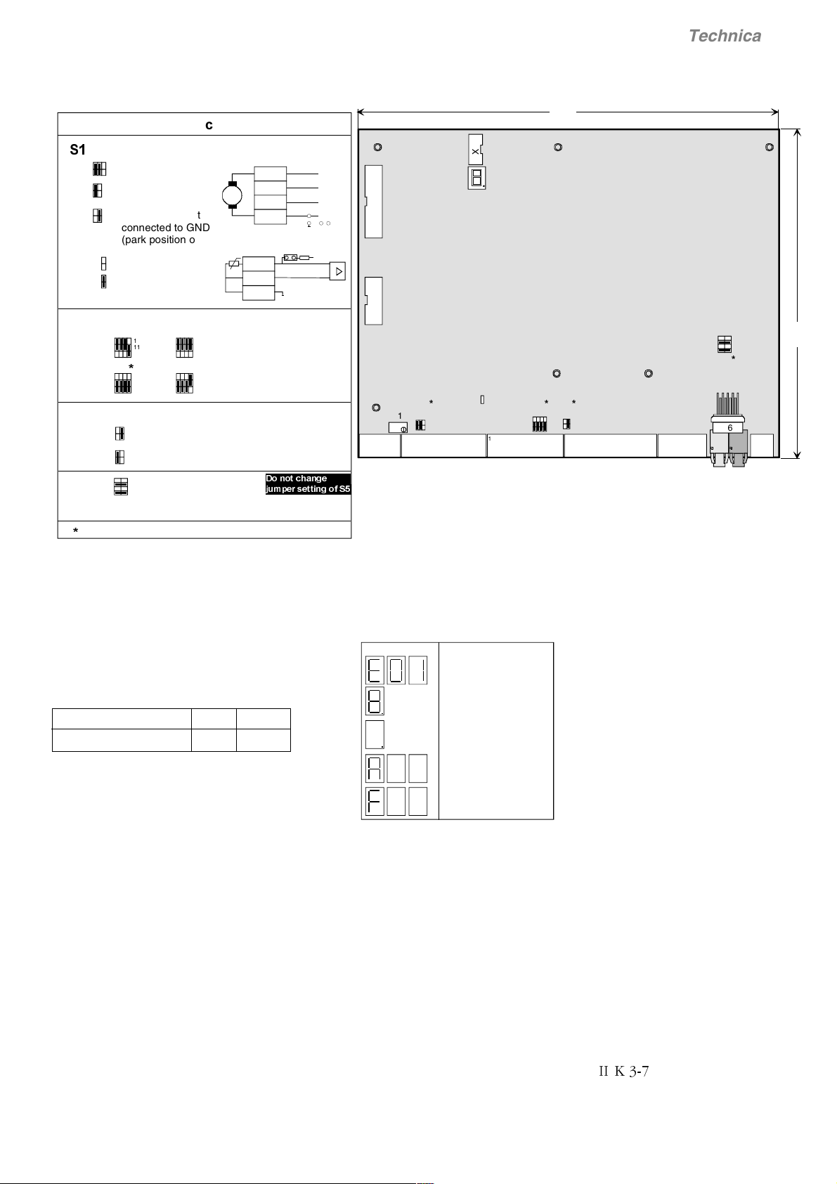
3.5 Control Board SDCS-CON-3A
Technical data
-XPSHUFRGLQJ
Tacho and PTC
6
6
2
*
15
2
Tacho signal
1
connected to GND
2
Tacho signal not
1
connected to GND
-
T
+
(park position only)
6
5
6
5
Pulse encoder
6
single ended:
differential:
Firmware download
6
6
default value
AI2 as ref input
AI2 used for temp.
measurement via PTC
5 V 24 V
31112
2
1
5 V
31112
2
1
4
2
3
1
42
13
78
12
31112
2
10
10
Normal operation
Firmware download via RS232
Note: change Jumper position only if electronics is switched off
For firmware download via RS232
S5:1-2 and 5-6 have to be jumpered
S5:5-6 int.Micro-controller Flash Prom
S5:1-2 Boot Mode
1
24 V
31112
2
1
10
10
X2:3
Fig. 3.5/1 Layout of the control board SDCS-CON-3A
-
X1:1
-
2
-
3
4
4
5
'RQRWFKDQJH
MXPSHUVHWWLQJRI6
-
+
GND
S1:
56PTC
S1
2
+
1
34
GND
22 K
+10V
233.5
X7
X12X13
78
12
All supports are conductive
connected to GND
S1
R115
6
2
1
5
41 91 81 101 5 1
X1 X2 X3 X4 X5 X8
Meas. point
I
A act
3
2
1
S2
S4
12
2
4
11
3
1
10
S5
X6
V800
DDCS
190
RS232
2
Control functions (Watchdog)
The control board has an internal watchdog. The
watchdog trip has the following effects:
- Thyristor firing control is reset and disabled.
- Digital outputs are forced to '0 V'.
Supply voltage monitoring
Supply voltage +5 V Mains
Undervoltage tripping level +4.50 V £97 VAC
If +5 V drops under the tripping level, it causes a
master reset by hardware. All I/O registers are forced
to 0 and the firing pulses are suppressed.
If mains monitor trips, firing pulses are forced to
inverter stability limit.
Serial interfaces
The control board SDCS-CON-3A has three serial
communication channels:
• X7: is a serial communication channel which is
used for
- DCS 400 PAN
- Adapter (3AFE 10035368)
• X6: is a standard RS232 serial communication
channel. It is a 9-pin D-Sub female connector
• V800 is an integrated channel and can be used
for Fieldbus Adapter by using optical fibre
Seven segment display
A seven segment display is located on the control
board and it shows the state of drive.
0.7s 0.7s 0.7s
RAM/ROM memory test error
Program is not running
Normal situation
Alarm
Fault
Fig. 3.5/2 Seven segment display of the SDCS-CON-3A
II K 3-7

Digital and analogue I/O connection of the SDCS-CON-3A
Technical data
6'&6&21
-
X1:1
X2:1
90-270 V
30-90 V
2
-
3
4
2
3
4
8-30 V
+
-
+
S1:
22 K
56
-
+
5
6
7
8
9
X3:1
120
Ω
2
3
120
Ω
4
5
120
Ω
6
7
8
X4:1
2
+5V +24V
4.75k
10k
3
4
5
6
7
8
9
10
1
X5:
2
3
4
5
123
45
78
10 11 12
470k
A
+10V
S2
22n
R115
3
4
6
9
2
1
GND
+5/+24V
+5/+24V
+5/+24V
100k
S1
100k 100k
+10V
-10V
100µ
100n
ChA +
ChA -
ChB +
ChB ChZ +
ChZ -
GND
Power-Source
100k
1n
1n
0V
47.5
+24 V/ ≤50 mA
100
µ
47n
0 V
Software
AITAC
AI1
AI2
AO1
AO2
DI1
DI2
DI3
DI4
DI5
DI6
DI7
DI8
+24V
DO1
DO2
DO3
DO4
Reso- Input/output Scaling Load Common Remarks
lution values by mode
[bit] Hardware range
±90...270 V
11 + sign ±30...90 V R 115/ ±20 V ➀ ➁
±8...30 V Software
11 + sign -11...0...+11 V Software ±20 V ➀ ➁
11 + sign -11...0...+11 V Software ±40 V ➀ ➁
£10* mA for external use
£10* mA e.g. reference pot.
11 + sign -11...0...+11 V Software £5 * mA
11 + sign -11...0...+11 V Software £5 * mA
Encoder supply Remarks
Inputs not isolated
max. frequency £300 kHz
5V/ 24V £ 200 mA* Selectable with jumper S2: 10-12
Input value Signal definition Remarks
by
0...+5 V Software
+15...+30 V
^
= "0" status
^
= "1" status
Output value Signal definition Remarks
by
50 * mA Software Current limit for all 4 outputs =
160 mA
The terminal connectors X1: ... X5: are removable. They cannot be
interchanged
Fig. 3.5/3 Terminal connection of the SDCS-CON-3A board
II K 3-8
➀ total smoothing time £2 ms
➁ -20...0...+20 mA by external 500 W resistor
* short circuit proof
Note
Unless otherwise stated, all signals are
referenced to a 0 V potential. On all PCBs,
this potential is firmly connected to the
unit's casing by means of plating-through
at the fixing points.
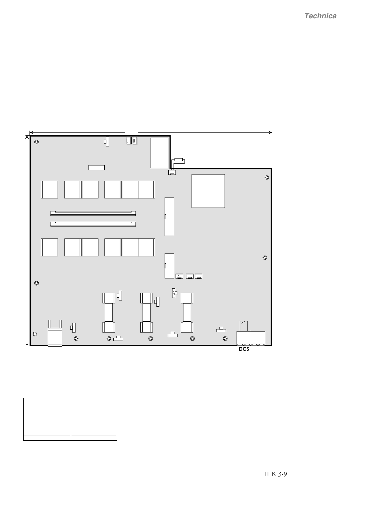
3.6 Power Interface Board SDCS-PIN-3A
The power interface board SDCS-PIN-3A is used
for all converter modules model A1...A4.
Functions:
- firing pulse circuits
- measurement of the armature current
- snubber circuit
- AC and DC voltage measurement
- heat sink temperature measurement
X6
258
X14
X11
- power supply for complete converter electronics
- fuses for field supply. Fuse data F100...F102:
T2
Technical data
Bussmann KTK-15A (600V)
PTC
X100
T24 T22 T26 T11 T15 T13
X15
X16
225
T14 T12 T16 T21 T25 T23
X1
F100
X24
X10
12
F+
to motor field
Fig. 3.6/1 Layout of the SDCS-PIN-3A board.
C1 U1 V1 W1 D1
X21
F-
X22
T1
X12X13
X3 X4 X5
X7
X2
F101
X23
F102
X20
X98
1234
Electronic
'2
supply
115...230 V
AC Supply voltage (X98:3-4)
Supply voltage 115...230 V AC
Tolerence -15%/+10%
Frequency 45 Hz ... 65 Hz
Power consumption 120 VA
Power loss £60 W
Inrush current 20 A/10 A (20 ms)
Mains buffering min 30 ms
Output X98:1-2 (DO5)
Potential isolated by relay (N.O. contact)
MOV- element (275 V)
Contact rating: AC: £250 V~/ £3 A~
DC: £24 V-/ £3 A-
or £115/230 V-/ £0.3 A-)
II K 3-9
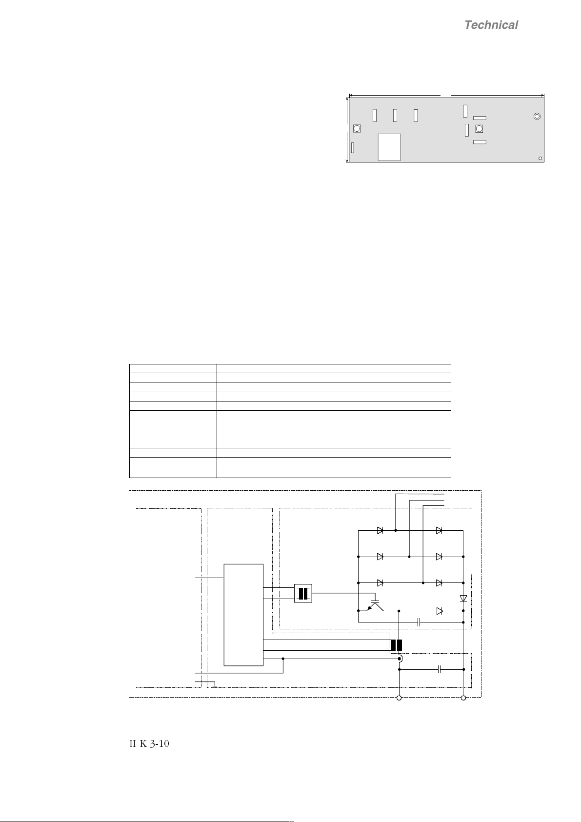
3.7 Field exciter SDCS-FIS-3A
Technical data
The DCS 400 converter has an build-in three-phase
field exciter with the following features:
X7
X2
X1
• smoothed field voltage
- better commutation of the motor
- increased brush life
45
T100
X14
• less heat generation in the motor
• less effort of cabling
Remark:
Fig. 3.7/1 Layout of the SDCS-FIS-3A field exciter
board
The DC link capacitor of the IGBT based field exciter
serves as an overvoltage protection for the armature
converter.
Overloading of the DC link capacitor is prevented by
the connected motor field winding.
The energy of glitches caused by the commutation of
the armature converter is no longer waste energy but
is used by the field exciter.
The overvoltage protection only works if a field winding is connected.
Therefore DCS400 can not be used with disconnected field.
Electrical data of SDCS-FIS-3A
AC input voltage: 230 V...500 V ±10%; three-phase
DC output voltage 50...440 V programmable
AC input current: £ output current
AC isolation voltage: 600 V
Frequency: same as DCS converter module
DC output current: 0.1 A...4 A for armature converter modules from 20 A to 25 A
Power loss see chapter 3.3
Terminal X10:1,2 on SDCS-PIN-3A
Cross sectional area 4 mm²
0.1 A...6 A for armature converter mod. from 45 A to 140 A
0.3 A...16 A for armature converter mod. from 180 A to 550 A
0.3 A...20 A for armature converter mod. for ³ 610 A
145
SDCS-FIS-3A
X6
X5
X4
X3
SDCS-CON-3A
FPWM
SDCS-PIN-3A SDCS-FIS-3A
X12: X12:
26
26
low level
control
3
1
X14:
Converter
8
IFM
989
GND
Fig. 3.7/2 Diagram of the field exciter unit
II K 3-10
U1
V1
X2 X7
X1
3
1
X14:
X11:2
3
X100:1-2 X6:1-3
X10:2 X10:1
(for motor field)
W1
X6X4X3
DC Output
Technical data
I
[A]
0,1
0,01
10
F
1
6
4
0.5
0 50 100 150 200 250 300 350 400 450
DCS 40x.0020...DCS 40x.0140
0.1
220
Fig. 3.7/3 Operating area of field exciter 0.1...6 A
100
I
F
[A]
20
10
16
DCS 40x.0180...DCS 40x.1000
System con- Field
nection voltage
range
U
Line
[V~] [V-]
230 50...237
380 50...392
400 50...413
415 50...428
440 50...440
460 50...440
480 50...440
500 50...440
Table 3.7/1:
Field voltage range related to
U
[V]
F
specified input voltage
1
0,1
1.5
0.3
0 50 100 150 200 250 300 350 400 450
220
Fig. 3.7/4 Operating area of field exciter 0.3...20 A
Important note:
Nominal field voltage and field current of the motor has to be within the field
controller operating range. For application with constant field it is easy to
check:
Transfer values of field current and field voltage to the diagram and check
that the point of intersection is within the operating range.
10
I
F
[A]
2SHUDWLQJUDQJH
0,1
1
out of operating range
U
[V]
F
Example:
For field weakening application do that check with
nominal values and minimal values. Both points of
intersection have to be within the operating range.
Depend on the converter use the right diagram
1
(6 A or 20 A)
e.g. DCS401.0045
Ue 310 V / Ie 0.3 A
è 6A diagram è ok
Depend on the converter use the right diagram
2
(6 A or 20 A)
e.g. DCS402.0050
Ue
310 V / Ie
nom
è 6A diagram è ok
nom
0.4 A
0,01
0 50 100 150 200 250 300 350 400 450
Fig. 3.7/5 Example of Field exciter operating range
Ue
100 V / Ie
min
è 6A diagram è not ok, not to realize !
U
[V]
F
0.2 A
min
II K 3-11
3.8 Ciruit diagrams
F
D
9
/
1
;
Technical data
F
D
9
/
1
;
0
F
F
D
D
9
9
/
1
;
0
0
:
/
9
/
6
6
/
.
8
/
7
(
3
$
6
6
/
.
7
6
6
/
.
7
2
5
'
5
$
2
%
(
&
$
)
5
(
7
1
,
5
(
:
2
3
;
;
;
$
1
,
3
7
7
;
;
;
;
;
'
9
9
.
.
*
**
9
9
.
..
*
*
9
9
.
*
0
9
.
.
*
7
;
.*.*.*
7
;
*.*.
7
7
7
;
;
;
;
9
**
.*.*
7
;
9
9
.
..
*
*
'
5
$
2
%
(
&
$
)
5
(
7
1
,
'
/
(
,
$
)
*
.*.**.
7
;
7
7
7
;
;
;
9
9
.
*
&
;
;
$
;
6
,
;
)
.*.
;
;
;
;;
;
;
/
;;
;
;
7
;
;
)
/
;
.
98
&
:
;
;
)
)
&
'
;
;
(
/
8
'
2
0
5
(
7
5
(
9
1
2
&
'
5
$
2
%
$
/
2
5
1
7
1
2
2
&
$
&
;
;
;
;
;
;
Fig. 3.8/1 Circuit diagram 4-Q converter
II K 3-12
O
H
Q
D
3
I
;
;
;
9
;
F
D
'
9
$
$
$
$
H
H
H
]
]
L
]
L
L
V
V
V
U
U
U
H
H
W
H
W
W
U
U
U
H
H
H
Y
Y
Y
Q
Q
Q
R
R
R
F
F
F
U
U
U
R
R
I
R
I
I
G
G
G
H
H
H
V
V
V
X
X
X
\
\
O
\
O
O
Q
Q
Q
R
R
R
F
D
9
/
1
;
Technical data
F
D
9
/
1
0
;
F
F
D
D
9
9
/
1
0
;
0
:
/
9
/
6
6
/
.
8
/
7
(
3
6
6
/
.
7
6
6
/
.
7
2
5
;
;
;
'
5
$
2
%
(
&
$
)
5
(
7
1
,
$
5
(
:
1
,
2
3
3
$
7
7
;
;
;
;
;
'
9
.
*
9
.
*
9
.
*
0
9
.
*
7
;
.*.*.*
7
;
*.*.
7
7
;
;
;
9
.
*
.*.*
7
7
7
;
;
;
9
.
*
&
'
5
$
2
%
(
&
$
)
5
(
7
1
,
'
/
(
,
)
$
*
.*.**.
7
7
7
;
;
;
;
;
$
;
6
,
;
)
.*.
;
;
;
;;
;
;
/
8
9
&
;;
;
;
7
;
;
/
;
:
;
;
)
)
)
.
&
'
;
;
(
/
8
'
2
0
5
(
7
5
(
9
1
2
&
'
5
$
2
%
$
/
2
5
1
7
1
2
2
&
&
$
;
;
;
;
;
;
Fig. 3.8/2 Circuit diagram 2-Q converter
O
H
Q
D
3
I
;
;
;
9
;
F
D
'
9
$
$
$
$
H
H
H
]
]
L
]
L
L
V
V
V
U
U
U
H
H
W
H
W
W
U
U
U
H
H
H
Y
Y
Y
Q
Q
Q
R
R
R
F
F
F
U
U
U
R
R
I
R
I
I
G
G
G
H
H
H
V
V
V
X
X
X
\
\
O
\
O
O
Q
Q
Q
R
R
R
II K 3-13

Technical data
II K 3-14

4 Overview of software
(The software delivered may contain minor changes to the product described here.)
Overview of Software
Parameter
The parameters of the converter are subdivided into
functional groups. These groups are listed in the table
below.
Parameter group Functions
1 - Motor Settings Motor settings, actual line
values, auto reclosing
2 - Operating Mode Macro selection, behaviour
during switching on/off, control/status information, control location
3 - Armature Actual value signals, high
current dosage, controller
settings, stall protection, reference sources
4 - Field Actual value signals, con-
troller settings, overcurrent/
undercurrent tripping, flux
adaptation, field heating
5 - Speed Controller Reference sources, actual
value acquisition, controller
settings, ramp generator,
constant speeds, alternative
settings, speed monitoring,
actual value filtering
6 - Input/Output Scaling and allocation of the
analog and digital inputs and
outputs, display selection for
the control panel, field bus
allocation, actual value signals
7 - Maintenance Language selection, service
procedures, diagnostics,
fault and alarm information,
square-wave generator
8 - Field Bus Serial communication via the
field bus, RS232 or panel
adapter
9 - Macro Adaptation Re-configure digital inputs
DI1...DI4 of macros 1, 5, 6,
7, and 8.
Parameter saving
Any changes of the parameters are stored automatically in the FlashProm of the converter. The
storage is executed in a time interval of approx. 5
seconds.
Function menu
Special functions of the control panel are listed in the
table below.
Menu function Significance
Set Typecode Typecode adaptation for re-
placement of SDCS-CON-3
Read Faultlogger Read / Clear the last 16
Faults or Alarms
Factory Settings Reset all parameters to fac-
tory values (default values)
Copy to Panel Parameter uploading from
drive to control panel
Copy to Drive Parameter downloading
from control panel to drive
Long/Short Par List Some parameter visible / in-
visible
Panel Lock Lock the control panel for
maloperation
LCD Contrast Contrast of cotrol panel dis-
play
Commissioning Guided commissioning via
control panel
Continual parameter writing destroys the FlashProm
Parameter are saved automatically in a background
routine. This is done approx. every 5 seconds, when:
• parameters are altered by means of the control
panel.
• parameters are transmitted by means of PC Tool
Drive Window Light, irrespective of whether the
content of the parameter has changed.
• parameters are transmitted by means of PLC
communication via one of the three serial ports
Field bus adapter or RS232-Port or PanelPort, irrespective of whether the parameter’s
content has changed.
Continual transmission of a parameter with the
same content will entail continual saving in the
background routine, i.e. even if the value of the
parameter does not change, the save routine will still
be activated.
A FlashProm of the present-day generation can be
written on and erased up to 100,000 times. This
means 100,000 x 5 seconds = approx. 6 days.
Continual transmission of parameters may destroy this FlashProm after approx. 6 days, which
is why parameters should only be transmitted if
the values involved have changed.
II K 4-1
4.1 General information about application Macros
Overview of Software
Macros are pre-programmed parameter sets. During start-up, the
drive can be configured easily without changing individual parameters.
The functions of all inputs and outputs and of allocations in the
control structure are influenced by the selection of a macro. Any
allocation which can be set manually with a “selector” (parameter) is
preset by the selection of a macro. The means, whether the drive is
speed-controlled or torque-controlled, whether supplementary references are processed, which actual values are available at the
Selector Remark
Cmd Location (2.02) Control location
Cur Contr Mode (3.14) Current controller operating mode
Torque Ref Sel (3.15) Torque reference source
Speed Ref Sel (5.01) Speed reference source
Alt Par Sel (5.21) Switching event for alternative speed
control parameters
Aux Sp Ref Sel (5.26) Auxiliary reference source
AO1 Assign (6.05) Actual value output at analog output AO1
AO2 Assign (6.08) Actual value output at analog output AO2
DO1 Assign (6.11) Signal output at digital output DO1
DO2 Assign (6.12) Signal output at digital output DO2
DO3 Assign (6.13) Signal output at digital output DO3
DO4 Assign (6.14) Signal output at digital output DO4
DO5 Assign (6.15) Signal output at digital output DO5
MSW bit 11 Ass (6.22) Signal transmission in bit 11 of the status
word
MSW bit 12 Ass (6.23) Signal transmission in bit 12 of the status
word
MSW bit 13 Ass (6.24) Signal transmission in bit 13 of the status
word
MSW bit 14 Ass (6.25) Signal transmission in bit 14 of the status
word
Jog 1 (9.02) Jogging 1 function via Fixed Speed 1
(5.13)
Jog 2 (9.03) Jogging 2 function via Fixed Speed 2
(5.14)
COAST (9.04) Coast stop function
User Fault (9.05) external User Fault event
User Fault Inv (9.06) external User Fault (invers) event
User Alarm (9.07) external User Alarm event
User Alarm Inv (9.08) external User Alarm (inverse) event
Dir of Rotation (9.09) Direction of Rotation only for speed con-
trolled drive
Mot Pot Incr (9.10) Motor Potentiometer Increment to in-
crease speed ref.
Mot Pot Decr (9.11) Motor Potentiometer Decrement to de-
crease speed ref.
analog outputs, which reference value sources are used, etc. is
already defined in the macro.
A macro is selected in the Macro Select (2.01) parameter. After
selection a function is assigned to each of the digital inputs DI1…DI8.
The functions are described in the chapter Application Macros.
The following “selectors” (parameters) are predefined when you are
selecting the macro provided that these parameters have their
default settings or are set to Macro Depend:
Selector Remark
MotPotMinSpeed (9.12) Motor Potentiometer Minimum Speed ref.
Ext Field Rev (9.13) external Field Reversal via external field
reversing switch
AlternativParam (9.14) switch over between Standard Parame-
ter Set and Alternative Parameter Set
Ext Speed Lim (9.15) external Speed Limitation via Fixed Speed
1 (5.13)
Add AuxSpRef (9.16) additional aux. speed ref.
Curr Lim 2 Inv (9.17) second current limitation via Arm Cur Lim
2 (3.24)
Speed/Torque (9.18) switch over between speed controlled
and torque controlled drive
Disable Bridge1 (9.19) block thyristor bridge 1
Disable Bridge2 (9.20) block thyristor bridge 2
Then the allocations will be dependent on the selected macro, see
chapter
The user can
are no longer “
allows the flexible, user-friendly adaptation to special requirements.
In addition to analog and digital outputs some of the digital inputs are
re-configurable. The digital inputs DI1…DI4 in macros 1+5+6+7+8
can be set individually via parameter group 9 - MacroAdaptation.
Macros 2+3+4 are fixed, not re-configurable.
Example of MacroAdaptation:
• Set parameter „Dir of Rotation" (9.09) from Macro depend to
• Set parameter „AlternativParam" (9.14) from Macro depend to
• Set standard parameter set (5.07…5.10) and alternative
Application Macros
change
Macro Depend
macro 6 - MotorPot should be selected
digital input DI1 should be re-defined from "direction of rotation"
to "alternativ parameter set" for using ramp 1 / 2
Disable
DI1
parameter set (5.22…5.25) to values as required
.
the allocations manually any time. Then they
”. Hence the macro technique also
II K 4-2
Overview of Software
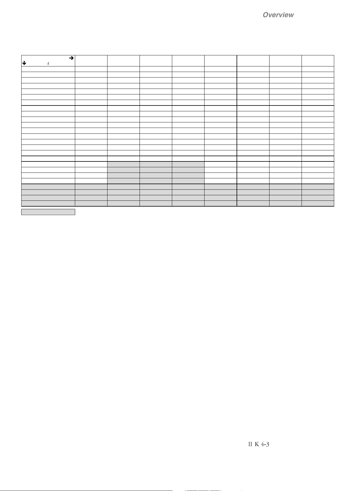
Overview of factory settings of macro-dependent parameters:
Macro
Ï
Parameter Standard Man/Const Sp Hand/Auto Hand/MotPot Jogging Motor Pot ext Field Rev Torque Ctrl
Cmd Location (2.02) Terminals Terminals Terminals Terminals Terminals Terminals Terminals Terminals
Cur Contr Mode (3.14) Speed Contr Speed Contr Speed Contr Speed Contr Speed Contr Speed Contr Speed Contr Torque Contr
Torque Ref Sel (3.15) AI2 AI2 Const Zero AI2 Const Zero AI2 AI2 AI1
Speed Ref Sel (5.01) AI1 AI1 AI1 AI1 AI1 Const Zero AI1 Const Zero
Alt Par Sel (5.21) Sp < Lev1 Digital Input 4 Sp < Lev1 Sp < Lev1 Sp < Lev1 Sp < Lev1 Sp < Lev1 Sp < Lev1
Aux Sp Ref Sel (5.26) Const Zero Const Zero Const Zero Const Zero AI2 Const Zero Const Zero Const Zero
AO1 Assign (6.05) Speed Act Speed Act Speed Act Speed Act Speed Act Speed Act Speed Act Speed Act
AO2 Assign (6.08) Arm Volt Act Arm Cur Act Arm Cur Act Arm Cur Act Torque Act Arm Volt Act Arm Volt Act Torque Act
DO1 Assign (6.11) Rdy for Run Rdy for On Rdy for On Rdy for On Rdy for Run Rdy for Run Rdy for Run Rdy for Run
DO2 Assign (6.12) Running Running Running Running Zero Speed Speed Level 1 Running Running
DO3 Assign (6.13) Zero Speed Fault Fault Fault At Setpoint Speed Level 2 Field Rev Act Zero Speed
DO4 Assign (6.14) Flt or Alarm Zero Speed Zero Speed Zero Speed Flt or Alarm Flt or Alarm Flt or Alarm Flt or Alarm
DO5 Assign (6.15) Main Cont On Main Cont On Main Cont On Main Cont On Main Cont On Main Cont On Main Cont On Main Cont On
MSW Bit11 Ass (6.22) none none none none none none none none
MSW Bit12 Ass (6.23) none none none none none none none none
MSW Bit13 Ass (6.24) none none none none none none none none
MSW Bit14 Ass (6.25) none none none none none none none none
Assignment of DI1 Jog 1 Start
Not re-configurable
Í
DI2 Jog 2 Stop Hand/Auto Jog 1 Jog 1 Incr. Speed Jog 1 not used
DI3 External Fault Direc of Rotat. Direc of Rotat. Direc of Rotat. Jog 2 Decr. Speed External Fault External Fault
DI4 External Alarm Ramp 1 / 2 AI1/Fixed Sp 1 AI1/MotPot not used Min Speed External Alrm External Alrm
DI5 Emerg. Stop Emerg. Stop Emerg. Stop Emerg. Stop Emerg. Stop Emerg. Stop Emerg. Stop Emerg. Stop
DI6 Reset Reset Reset Reset Reset Reset Reset Reset
DI7 On/Off Fixed Speed 1 Direc of Rotat. Incr. Speed On/Off On/Off On/Off On/Off
DI8 Run Fixed Speed 2
12345678
Start/Stop Hand
Start/Stop Auto
Start/Stop Direc of Rotat. Direc of Rotat. Ext Field Rev Coast
Decr. Speed Run Run Run Run
II K 4-3

4.2 Application Macros
The following application macros are available:
Overview of Software
Macro 1: Standard
Drive switch-on/switch-off and enable via 2
digital inputs.
Speed reference via analog input.
External torque limiting via analog input.
Jogging via 2 digital inputs.
2 digital inputs for external events (fault/
alarm).
2 digital inputs for emergency stop and fault
acknowledgement.
Macro 2: Man/Const Sp
Starting and stopping of the drive via 2 digital
inputs.
Speed reference via analog input.
Reversal of rotational direction via 1 digital input.
2 ramp sets selectable via 1 digital input.
Selection of speed reference or 2 fixed
speeds via 2 digital inputs.
2 digital inputs for emergency stop and fault
acknowledgement.
Macro 3: Hand/Auto
Switchover between manual and auto. control
effected via 1 digital input.
Manual control:
Starting and stopping of the drive via 1 digital input.
Speed reference via analog input 1.
Selection of speed reference or 1 fixed
speed via 1 digital input.
Reversal of rotational direction via 1 digital input.
Automatic control:
Starting and stopping of the drive via 1 digital input.
Speed reference via analog input 2.
Reversal of rotational direction via 1 digi-
tal input.
2 digital inputs for emergency stop and fault
acknowledgement.
Macro 4: Hand/MotPot
Starting and stopping of the drive via 1 digital
input.
Jogging via 1 digital input.
Speed reference via analog input.
Reversal of rotational direction via 1 digital input.
Motor potentiometer function via 2 digital inputs.
Selection of speed reference or motor pot via
1 digital input.
2 digital inputs for emergency stop and fault
acknowledgement.
Macro 5: Jogging
Drive switch-on/switch-off and enable via 2 digital inputs.
Speed reference via analog input 1.
Additional reference via analog input 2.
Jogging via 2 digital inputs.
Reversal of rotational direction via 1 digital input.
2 digital inputs for emergency stop and fault
acknowledgement.
Macro 6: Motor Pot
Drive switch-on/switch-off and enable via 2 digital inputs.
Reversal of rotational direction via 1 digital input.
Minimum speed can be activated via 1 digital
input.
Motor pot function via 2 digital inputs.
2 digital inputs for emergency stop and fault
acknowledgement.
Macro 7: ext Field Rev
Drive switch-on/switch-off and enable via 2 digital inputs.
Speed reference via analog input 1.
External torque limiting via analog input 2.
Jogging via 1 digital input.
External field reversal can be activated via 1
digital input.
2 digital inputs for external events (fault/
alarm).
2 digital inputs for emergency stop and fault
acknowledgement.
Macro 8: Torque Ctrl
Drive switch-on/switch-off and enable via 2 digital inputs.
Torque reference via analog input.
Coast Stop via 1 digital input.
2 digital inputs for external events (fault/
alarm).
2 digital inputs for emergency stop and fault
acknowledgement.
II K 4-4

Overview of Software
II K 4-5
4.2.1 Macro 1 - Standard
Description of I/O’s functionality
I/O Param Function
DI1 Jog speed 1. Speed can be defined in parameter 5.13.
DI2 Jog speed 2. Speed can be defined in parameter 5.14.
DI3 2.01 External fault signal. Triggers a fault response and trips the drive
DI4 External alarm signal. Triggers a warning in DCS400
DI5 Emergency stop. Closed-circuit principle, must be closed for operation
DI6 Reset. Faultacknowledgement, reset faults signaled by the drive
DI7 Drive ON / OFF. DI7=0=OFF , DI7=1=ON
DI8 Drive START / STOP. DI8=0=STOP , DI8=1=START
DO1 6.11 Ready for Run. Converter switched ON, but not yet STARTed
DO2 6.12 Running. Drive is STARTed (Current controller enabled)
DO3 6.13 Zero-speed signal. Motor at standstill
DO4 6.14 Group fault signal. Common signal for all faults or alarms
DO5 6.15 Main contactor on. Controlled by ON command (DI7)
AI1 5.01 Speed reference
AI2 3.15 External torque limitation possible. First the parameter Cur Contr Mode 3.14 has to be changed
AO1 6.05 Speed actual
AO2 6.08 Armature voltage actual
Inter locking of Jog speed 1 – Jog speed 2 – Drive START
Jog 1
DI1
Overview of Software
Accel/Decel Ramp for Jogging can be defined in parameter 5.19/5.20.
Accel/Decel Ramp for Jogging can be defined in parameter 5.19/5.20.
from Macro depend to Lim Sp Ctr. Without changes the factory settings for torque limitation is
effective (100%).
Jog 2
DI2
0 0 0 Drive is STOPped (Current controller disabled)
1 0 0 Drive STARTed via DI1 , speed reference=parameter 5.13
x 1 0 Drive STARTed via DI2 , speed reference=parameter 5.14
x x 1 Drive STARTed via START command (DI8) , speed reference via analog input AI1
START
DI8
Drive is ON (DI7=1)
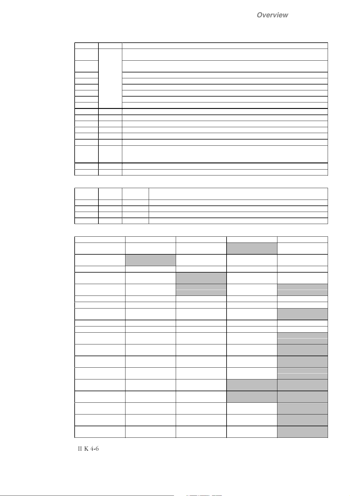
Parameter settings, shaded areas are set by macro - all others are set during commissioning
1 - Motor Settings 2 - Operation Mode 3 - Armature 5 - Speed Controller 6 - Input/Output
1.01 Arm Cur Nom 2.01 Macro Select
[Standard]
1.02 Arm Volt Nom 2.02 Cmd Location
[Terminals]
1.03 Field Cur Nom 2.03 Stop Mode 3.08 Torque Lim Neg 5.03 Encoder Inc 6.03 AI2 Scale 100%
1.04 Field Volt Nom 2.04 Eme Stop Mode 3.14 Cur Contr Mode
1.05 Base Speed 3.15 Torque Ref Sel
1.06 Max Speed 3.17 Stall Torque 5.11 Eme Stop Ramp 6.06 AO1 Mode
3.04 Arm Cur Max 5.01 Speed Ref Sel
[AI1]
3.07 Torque Lim Pos 5.02 Speed Meas
Mode
5.09 Accel Ramp 6.04 AI2 Scale 0%
[Speed Contr]
5.10 Decel Ramp
[AI2]
3.18 Stall Time 5.12 Ramp Shape 6.07 AO1 Scale 100%
5.13 Fixed Speed 1 6.08 AO2 Assign
5.14 Fixed Speed 2 6.09 AO2 Mode
5.15 Zero Speed Lev 6.10 AO2 Scale 100%
5.16 Speed Level 1 6.11 DO1 Assign
5.17 Speed Level 2 6.12 DO2 Assign
5.19 Jog Accel Ramp 6.13 DO3 Assign
5.20 Jog Decel Ramp 6.14 DO4 Assign
5.21 Alt Par Sel
[Sp < Lev1]
5.26 Aux Sp Ref Sel
[Const Zero]
6.01 AI1 Scale 100%
6.02 AI1 Scale 0%
6.05 AO1 Assign
[Speed Act]
[Arm Volt Act]
[Rdy for Run]
[Running]
[Zero Speed]
[Flt or Alarm]
6.15 DO5 Assign
[Main Cont On]
6.22 MSW Bit 11 Ass
[none]
6.23 MSW Bit 11 Ass
[none]
6.24 MSW Bit 11 Ass
[none]
6.25 MSW Bit 11 Ass
[none]
II K 4-6
 Loading...