

Page 1
Page 2
41-151.1H Type D-3 Direct Current Relay
Sketch
205342
182A787
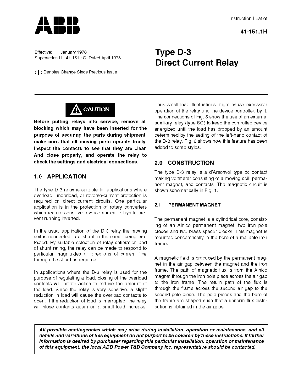
Figure 1: Schematic Drawing of Magnetic Circuit of Type
D-3 Relay (Top View). Moving Coil Bearing Supports, Springs and Contacts Omitted.
2.2 MOVING COIL
The moving coil rotates in the air gap between the
core and the iron frame. Electrical connections are
made to the coil through two springs located at the
top of the element. One end of each spring is connected through a lever am to a head of the coil.
cache other end of each spring is fastened to posts
mounted in a circular insulation plate. This plate can
be rotated to permit adjustment of the zero position
of the moving element.
A third spiral spring located at the bottom of the element provides a current path to the moving contact.
2.3 AUXILIARY SWITCH (CS-1) (WHEN USED)
The auxiliary switch is a small solenoid type switch. A
cylindrical plunger with a silver disc mounted on its
lower end moves in the core of the solenoid. As the
plunger travels upward the disc bridges three silver
stationary contacts.
2.4 OPERATION INDICATOR (WHEN USED)
The operation indicator consists of a small solenoid
coil mounted in a steel frame, a spring restrained
armature and a white flag. The indicator is reset by a
push rod in the cover.
Figure 2: Internal Schematic of the Type D-3 Relay in the
Type FT-21 Case.
3.0 OPERATION
The D-3 relay operates on the principle of a current
carrying conductor (moving coil) located in a magnetic field (permanent magnet). When a current is
applied to the coil of the relay, a torque is produced
that rotates the moving coil until the electrical torque
is equal to the torque of the restraining spring. The
moving contact will assume a position in its travel
that is proportional to the current applied to the moving coil.
The direction of movement of the moving coil is
determined by the polarity of the current applied to
the roil. In the “left zero” and “suppressed zero” D-3
relays, the contacts will move to the right when a current of the proper magnitude and polarity is applied
to the relay. On the other hand, the contact of the
“center zero” relay will move either left or right
depending on the polarity and magnitude of the
applied current.
4.0 CHARACTERISTICS
The type D-3 relay is supplied in the standard ranges
listed in the table below. The numbers on the scale
indicate in millivolts the potential required at the relay
base terminals to operate the moving element to the
indicated scale position.
2
Page 3
Type D-3 Direct Current Relay 41-151.1H
183A342
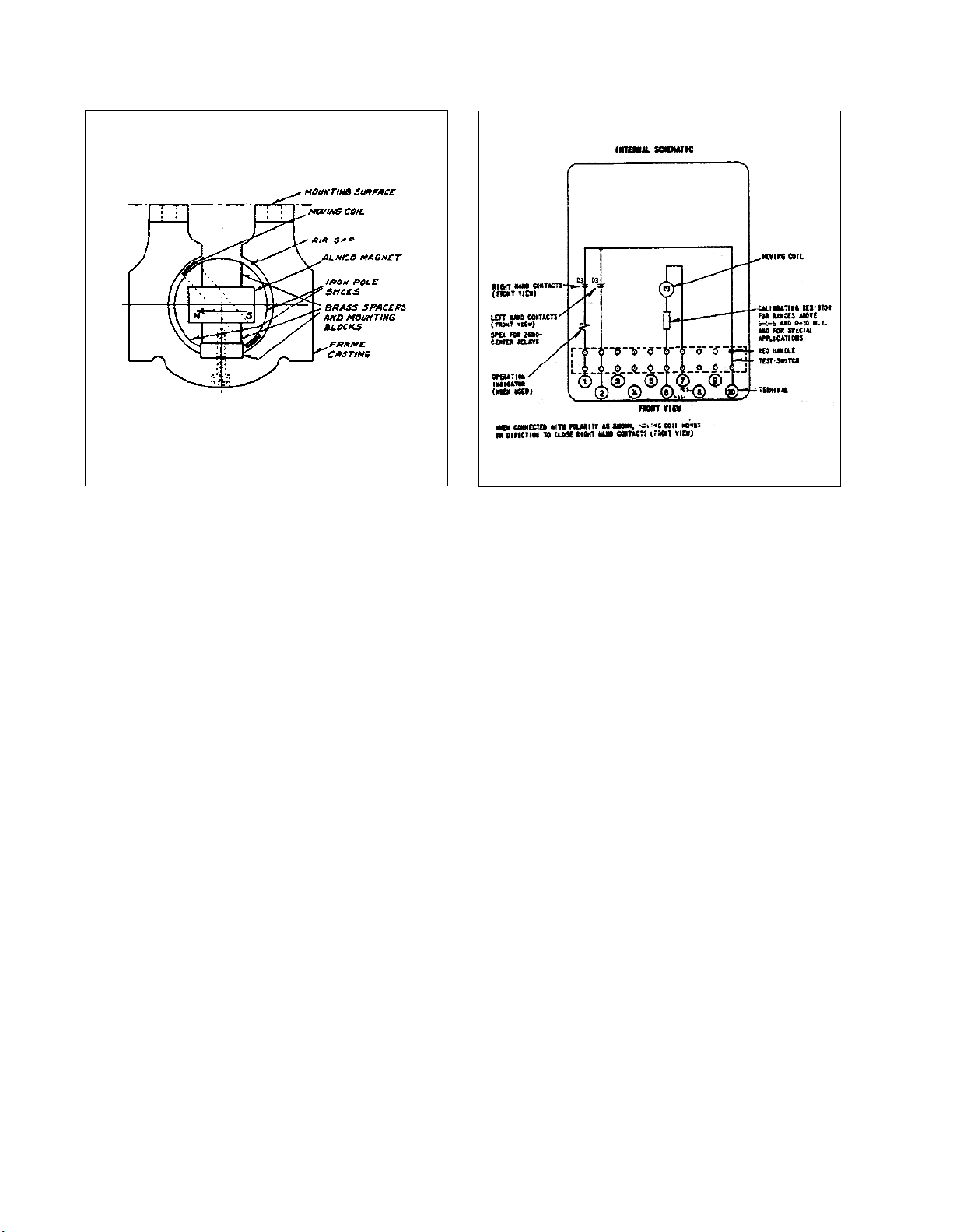
Figure 3: External Schematic Diagram for Overload or Re-
verse Current Protection, using the Type D-3 Relay.
MOVING COIL CIRCUIT
Ranges in
Millivolts, dc
Resistance in Ohms at 25°C
0-10
5-0-5
40-80
100-0-100
0-200
* Other ranges can also be supplied.
Average
0.3
0.3
1.2
6.0
6.0
As shown in the above Table, the D-3 relay is available with a “left zero,” “suppressed zero” and “center
zero” scale. In the “left zero” and the “suppressed
zero” relays the moving contact is located in the
extreme left hand position of the scale when the
relays are deenergized. The “suppressed zero” relay
is held in this position with considerable more force
than the “left zero” relay. When the relays are energized with voltages of the proper magnitude and
polarity, the moving contact moves to the right.
183A343
Figure 4: External Schematic Diagram for Overload Protec-
tion where Trip Currents in Excess of One Ampere
Rating Require Use of an Auxiliary Relay.
In the “center zero” relay, the moving contact is
located in the center of the scale when the relay is
deenergized. When the relay is energized, the contact will move either to the right or left depending
upon the polarity of the applied voltage.
A modification of the D-3 relay, in which a rectifier is
mounted internally, makes it suitable for ac operation. Full scale deflection can be obtained with 6 milliamperes ac Relays modified for AC volts can also be
supplied.
The relay has a slight time-delay, with inverse characteristics. In the usual application the moving coil
terminals are connected across a shunt, and this
results in longer delay for both operating and reset
times. When a shunt is used the operating time for
full scale travel at 125% of the full scale operating
current is about 4 seconds, while at 1000% it is about
.25 second. In applications where no shunt is used,
the operating times for the same conditions are about
1.25 and .15 second respectively. When the relay is
deenergized, the time required for it to reset from the
full scale position to the 10% position is approxi-
3
Page 4

41-151.1H Type D-3 Direct Current Relay
183A344
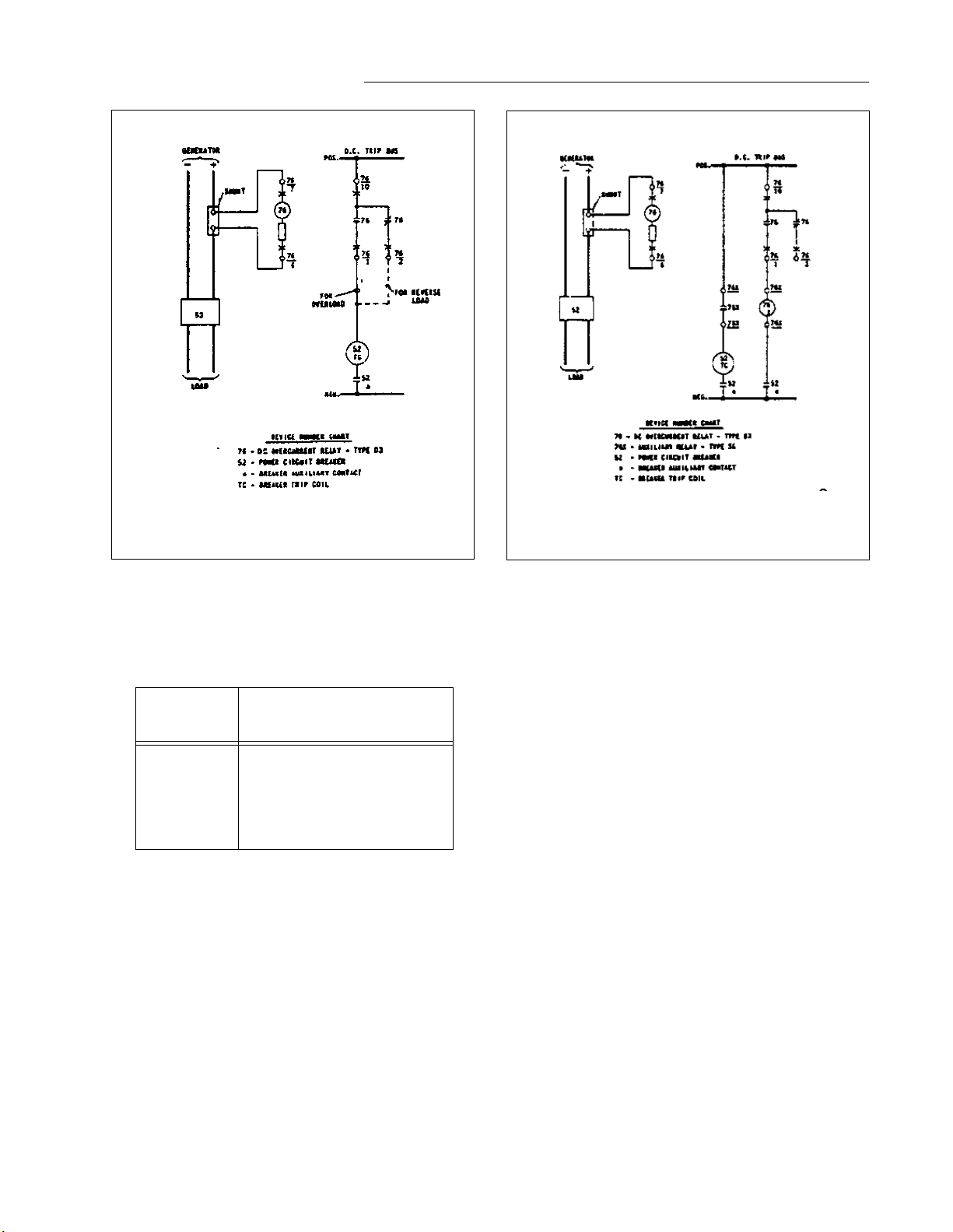
Figure 5: External Schematic Diagram for Use of External
Auxiliary Relay to Prevent Pumping of the Type D3 Relay when used for Overload Protection.
mately 5 seconds when a shunt is used, and 2 seconds when there is no shunt.
Continuous maximum overload is approximately
1500% of full scale.
The minimum setting which D-3 Relay can accommodate is 5% of the full scale.
5.0 SETTINGS
For reverse-current protection a sensitivity of 2 per
cent is obtained when using a standard 50 milli-volt
shunt and setting the relay at 1 millivolt. A 10 per
cent sensitivity is obtained by setting the relay at 5
millivolts. These values of sensitivity can be doubled
by using a 100 millivolt shunt.
For overload protection the relay is set at the index
setting which, with respect to the millivolt drop of the
shunt, will operate at desired per cent of overload.
182A785
Figure 6: Internal Schematic of the Type D-3 Relay in the
Type FT-21 Case with Self-Contained Auxiliary
Relay used to Prevent Pumping on Overload Protection.
5.1 TRIP CIRCUIT
Amperes contacts will:
(non-inductive load)
Contacts
D-3 relay
contactor switch
(when supplied)
dc control
voltage open close
125 V
250 V
125 V
250 V
0.04
0.02
3.5
1.0
1.0
1.0
3.0
3.0
carry
continuously
-------------
-------------
5.0
5.0
6.0 INSTALLATION
The relays should be mounted on switchboard panels or their equivalent in a location free from dirt,
moisture, excessive vibration, and heat. Mount the
relay vertically by means of the four mounting holes
on the flange for semi-flush mounting or by means of
the rear mounting stud or studs for projection mounting. Either a mounting stud or the mounting screws
may be utilized for grounding the relay. The electrical
4
Page 5

Type D-3 Direct Current Relay 41-151.1H
182A786
Figure 7: Internal Schematic of the Type D-3 in the Type
FT-21 Case with Two Self-Contained Auxiliary
Relays used to Increase Contact Capacity.
connections may be made directly to the terminals by
means of screws for steel panel mounting or to the
terminal studs furnished with the relay for thick panel
mounting. The terminal studs may be easily removed
or inserted by locking two nuts on the stud and then
turning the proper nut with a wrench.
For detailed FT. case information refer to Instruction
Leaflet 41-076.
Standard D-3 relays are calibrated in millivolts measured at the relay terminals. Hence, the resistance of
the leads between the relay and the ammeter shunt
must be sufficiently low to avoid introducing an
excessive error in the relay indication. With the 0-10
or 5-0-5 millivolt relays, leads 8 feet long of 910 B&S
gauge copper wire will reduce the relay indication by
approximately 5%. if the lead length is less or the
conductor size is larger, the error will be correspondingly reduced. Relays with higher millivolt ranges
have proportionally greater internal resistances, and
consequently error due to lead resistance is reduced.
For example, a 0-100 millivolt relay with leads as
described above would have an error of 0.5% due to
lead resistance.
182A788
Figure 8: Internal Schematic of the Type D-3 Relay in the
Type FT-21 Case, Modified for ac Operation.
basis of 1000 amp. per square inch, at .20°C, 6 feet
of copper bus-bar will give 50 millivolts drop.
7.0 ADJUSTMENTS AND MAINTENANCE
The proper adjustments to insure correct operations
have been made at the factory. Upon receipt of the
relay, no customer adjustments, other than those
covered under “SETTINGS” should be required.
7.1 ACCEPTANCE CHECK
Check the scale markings by setting either of the two
adjustable contacts at a value marked on the scale.
Then alternately apply this voltage plus and minus
3%. The contacts should make and break.
Remove the adjustable contact from the setting and
set the second adjustable contact at the same point
on the scale. Alternately -apply this voltage plus and
minus 3%. The contacts should make and break.
7.2 ROUTINE MAINTENANCE
The use of standard ammeter shunts may be
avoided by connecting the moving element leads
over an equivalent length of bus-bar or cable. On a
All contacts should be cleaned periodically. A contact
burnisher S#182A836H0I is recommended for this
purpose. The use of abrasive material for cleaning
5
Page 6

41-151.1H Type D-3 Direct Current Relay
contacts is not recommended because of the danger
of embedding small particles in the face of the soft
silver and thus impairing the contact.
If the moving element should be removed, the bearing end-play should be checked when replacing it.
This should be from .020 inch to .025 inch, and can
be measured by inserting a feeler gauge between the
upper bearing screw and the shoulder on the moving
element shaft.
The core and moving coil assembly should not be
removed from the frame casting of the D-3 relay
unless a keeper having the same radius on the core
is placed on the core in such manner as to bridge the
iron pole pieces as the core is withdrawn from the
bore of the casting. It is necessary also to insert
spacers in the air gap so that the core will remain
approximately centered when the mounting screws
are removed, to prevent damaging the coil winding
when sliding the assembly out of the casting.
7.3 AUXILIARY SWITCH (CS-1)
Adjust the stationary core of the switch for a clearance between the stationary core and the moving
core when the switch is picked up. This can be done
by turning the relay upside-down. Then screw up the
core screw until the moving core starts rotating. Now
back off the core screw until the moving core stops
rotating. This indicates the points when the play in
the assembly is taken up, and where the moving core
just separates from the stationary core screw. Back
off the core screw approximately one turn and lock in
place. This prevents the moving core from striking
and sticking to the stationary core because of residual magnetism. Adjust the contact clearance for
3/64” by means of the two small nuts on either side of
the Micarta disc.
Block main contacts closed and energize trip circuit
with rated voltage. Contacts of auxiliary switch
(CS-1) should make.
7.4 OPERATION INDICATOR
The operation indicator (when used) consists of a
small solenoid coil mounted in a steel frame, a spring
restrained armature and a white flag. The indicator is
reset by a push rod in the cover. Block the CS-1 auxiliary relay contacts closed and pass 0.2 amperes AC
or DC through the indicator. The white target should
fall into view.
The coil has a dc resistance of approximately 2.8
ohms and a continuous current carrying capacity of
0.6 amperes.
8.0 REPAIRS AND RENEWAL PARTS
Repair work can be done most satisfactorily at the
factory. However, interchangeable parts can be furnished to the customers who are equipped for doing
repair work. When ordering parts, always give the
complete nameplate data.
6
Page 7

Type D-3 Direct Current Relay 41-151.1H
Figure 9: Type D-3 Relay without case. 1- Moving Coil. 2 - Current-carrying restraining springs. 3- Permanent Magnet.
4- Iron-Frame. 5- Scale. 6- Moving Contact. 7- Stationary Contacts.
7
Page 8

 Loading...