

Page 1

2TMD041800D0022│10.06.2019
Product manual
ABB-Welcome IP
D04012 Smart Access Point Lite
D04012-02 Smart Access Point Lite
Page 2

Table of contents
Product manual
2TMD041800D0022
│
2
Table of contents
1 Notes on the instruction manual....................................................................................................................... 4
2 Safety ................................................................................................................................................................. 4
3 Intended use...................................................................................................................................................... 4
4 Environment ...................................................................................................................................................... 5
4.1 ABB devices .......................................................................................................................................... 5
5 Product description ........................................................................................................................................... 6
6 Technical data ................................................................................................................................................... 8
7 Mounting/Installation ......................................................................................................................................... 9
7.1 Requirement for the electrician ............................................................................................................ 9
7.2 Mounting .............................................................................................................................................. 10
8 Commissioning ................................................................................................................................................ 11
8.1 Initial setup .......................................................................................................................................... 11
8.2 Main menu ........................................................................................................................................... 19
8.3 Preferences ......................................................................................................................................... 20
8.3.1 Entering the settings ............................................................................................................. 20
8.3.2 View the version information ................................................................................................. 20
8.3.3 Local firmware update........................................................................................................... 21
8.3.4 Online firmware update ......................................................................................................... 22
8.3.5 Reset to factory defaults ....................................................................................................... 25
8.3.6 Language ............................................................................................................................. 26
8.3.7 Network settings ................................................................................................................... 27
8.3.8 Backup and restore the project .............................................................................................. 28
8.3.9 3rd party authority................................................................................................................. 29
8.3.10 Check abnormal devices ....................................................................................................... 30
8.3.11 Searching the Onvif IPC........................................................................................................ 31
8.3.12 Time settings ........................................................................................................................ 33
8.3.13 Sync time with other devices ................................................................................................. 34
8.3.14 Offline alarm settings ............................................................................................................ 35
9 Operation ......................................................................................................................................................... 37
9.1 Deivce management ........................................................................................................................... 37
9.1.1 Adding devices ..................................................................................................................... 37
9.1.2 Changing the settings of the devices ..................................................................................... 43
9.1.3 Deleting devices ................................................................................................................... 46
9.1.4 Set the indoor station ............................................................................................................ 47
9.1.5 Set the outdoor station .......................................................................................................... 56
9.1.6 Set the guard unit ................................................................................................................. 68
9.1.7 Set the IP actuator ................................................................................................................ 70
9.2 User management ............................................................................................................................... 75
9.2.1 Enter the settings screen ...................................................................................................... 75
9.2.2 Adding users one by one ...................................................................................................... 76
9.2.3 Importing the users via a template ......................................................................................... 77
9.2.4 Assign the deives to the user ................................................................................................ 79
Page 3

Table of contents
Product manual
2TMD041800D0022
│
3
9.2.5 Changing user information .................................................................................................... 87
9.2.6 Deleting users ...................................................................................................................... 88
9.2.7 Logging in with different accounts .......................................................................................... 89
9.3 Notification ........................................................................................................................................... 90
9.3.1 Enter the Settings screen ...................................................................................................... 90
9.3.2 Alarm list .............................................................................................................................. 91
9.3.3 Device Fault ......................................................................................................................... 92
9.3.4 Call list ................................................................................................................................. 93
9.3.5 Unlock list ............................................................................................................................ 94
9.4 Message Center .................................................................................................................................. 95
9.4.1 Creating and sending a message .......................................................................................... 96
9.4.2 Viewing and replying to messages......................................................................................... 97
9.5 Emergency unlock ............................................................................................................................... 99
10 FCC................................................................................................................................................................ 100
11 Cyber security ............................................................................................................................................... 101
11.1 Disclaimer .......................................................................................................................................... 101
11.2 Performance and service and network performance ...................................................................... 101
11.3 Deployment guideline ....................................................................................................................... 102
11.4 Upgrading .......................................................................................................................................... 102
11.5 Backup/restore .................................................................................................................................. 103
11.6 Malware prevention solution ............................................................................................................. 103
Page 4

Notes on the instruction manual
Product manual
2TMD041800D0022
│
4
1 Notes on the instruction manual
Please read through this manual carefully and observe the information it contains. This will
assist you in preventing injuries and damage to property, and ensure both reliable operation and
a long service life for the device.
Please keep this manual in a safe place. If you pass the device on, also pass on this manual
along with it. ABB accepts no liability for any failure to observe the instructions in this manual.
2 Safety
Warning
Electric voltage!
Dangerous currents flow through the body when coming into direct or indirect
contact with live components.
This can result in electric shock, burns or even death.
– Disconnect the mains power supply prior to installation and/or disassembly!
– Permit work on the 100-240 V supply system to be performed only by
specialist staff!
3 Intended use
As a part of the ABB-Welcome IP system, this device can only be used with accessories from
the system
Page 5

Environment
Product manual
2TMD041800D0022
│
5
4 Environment
Consider the protection of the environment!
Used electric and electronic devices must not be disposed of with household
waste.
– The device contains valuable raw materials that can be recycled. Therefore,
dispose of the device at the appropriate collecting facility.
4.1 ABB devices
All packaging materials and devices from ABB bear the markings and test seals for proper
disposal. Always dispose of the packing materials and electric devices and their components via
an authorized collection facility or disposal company.
ABB products meet the legal requirements, in particular the laws governing electronic and
electrical devices and the REACH ordinance.
(EU-Directive 2012/19/EU WEEE and 2011/65/EU RoHS)
(EU-REACH ordinance and law for the implementation of the ordinance (EG) No.1907/2006)
Page 6

Product manual
2TMD041800D0022
│
6
5 Product description
12354
10
Product description
6
7
8
9
No. Function
1
2
3
4
5
6
7
8 Micro SD card connector (reserved)
9
10 Power input connector (DC-JACK input)
11 LAN (PoE)
USB stick connector (reserved)
Tamper switch
(1)
Status indicator
Binary input (used to interact with other systems)
Binary output (used to interact with other systems)
Reset button
Access point mode switch
When AP mode is activated, LED flashes red light.
Security switch
ON = does not allow new devices
OFF = allows new devices (default)
Page 7

Product manual
2TMD041800D0022
│
7
(1)
Status indicator
Operation LED status
Power on White, always on
In Access Point mode Red, always on
Ready for operation (not in AP mode) Green, always on
Temper swtich is triggered White, flash fast
Press reset button and hold for 10 s White, flash slowly
Product description
Page 8

Technical data
Product manual
2TMD041800D0022
│
8
6 Technical data
Designation Value
Rating voltage 24 V DC
Operating voltage range 20-27 V DC
Rating current 24 V DC, 375 mA
PoE standard IEEE802.3 af
Wireless transmission band
Wireless transmission power
Wireless transmission standard IEEE 802.11 a/b/g/n
Operating temperature -10 °C…+45 °C
802.11b/g/n:
2412...2462MHz (for United States)
2412...2472MHz (for European countries)
802.11a/n:
5150…5250MHz
5250…5350MHz
5470…5725MHz
5725…5850MHz (for United States)
Max. 20 dBm@12 Mbps OFDM 2.4 G
Max. 20 dBm@12 Mbps OFDM 5.8 G
Storage temperature -25 °C…+70 °C
Product dimensions 204 mm × 132 mm × 32 mm
IP level IP 30
IK level IK 05
Relay output 30 V DC, 1 A
Dry contact input 5 V DC, 1mA
Page 9

Mounting/Installation
Product manual
2TMD041800D0022
│
9
7 Mounting/Installation
Warning
Electric voltage!
Dangerous currents flow through the body when coming into direct or indirect
contact with live components.
This can result in electric shock, burns or even death.
– Disconnect the mains power supply prior to installation and/or disassembly!
– Permit work on the 100-240 V supply system to be performed only by
specialist staff!
7.1 Requirement for the electrician
Warning
Electric voltage!
Install the device only if you have the necessary electrical engineering
knowledge and experience.
– Incorrect installation endangers your life and that of the user of the electrical
system.
– Incorrect installation can cause serious damage to property, e.g. due to fire.
The minimum necessary expert knowledge and requirements for the installation
are as follows:
– Apply the "five safety rules" (DIN VDE 0105, EN 50110):
1. Disconnect
2. Secure against being re-connected
3. Ensure there is no voltage
4. Connect to earth and short-circuit
5. Cover or barricade adjacent live parts.
– Use suitable personal protective clothing.
– Use only suitable tools and measuring devices.
– Check the type of supply network (TN system, IT system, TT system) to
secure the following power supply conditions (classic connection to ground,
protective grounding, necessary additional measures, etc.).
Page 10
Mounting/Installation
Product manual
2TMD041800D0022
│
10
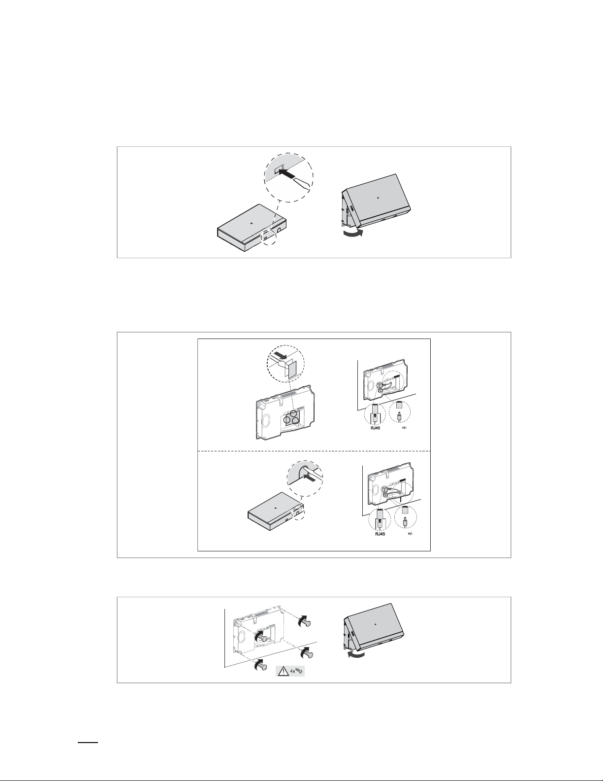
7.2 Mounting
1. Dismantle
Pull the clamp on the bottom of the device and then open the front cover.
2. Wiring
Option 1: Wiring from the back
Option 2: Wiring from the bottom
Option1
3. Mounting
Option2
Page 11
Commissioning
Product manual
2TMD041800D0022
│
11
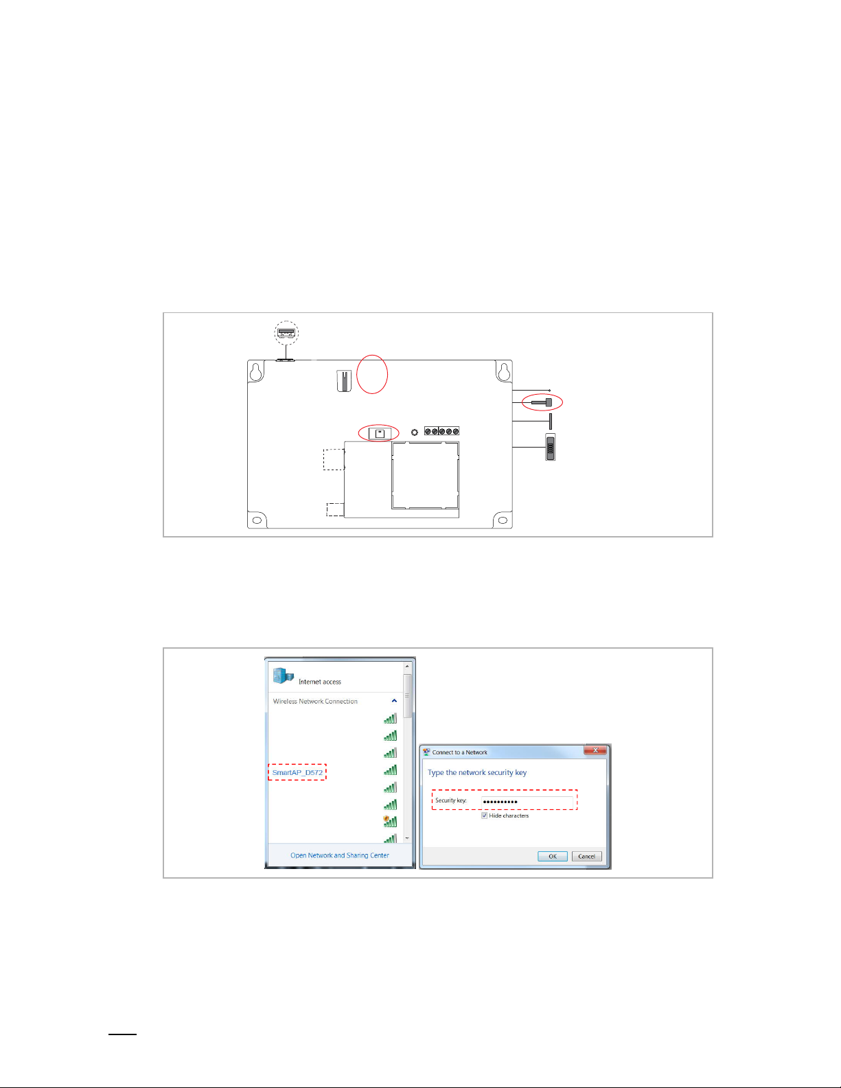
8 Commissioning
AP mode switch
8.1 Initial setup
1. Smart Access Point enters Access Point mode
Smart Access Point enters AP mode automatically when powered on for the first time or a
"System reset" is carried out from the "Preferences" screen.
You can also enter AP mode by pressing the AP mode switch.
The LED turns red if AP mode is entered successfully.
Label
LED
2. PC connects to Smart Access Point
If Smart Access Point is running in Access Point mode, there is a Wifi name of Smart Access
Point (e.g. SmartAP_xxx). Click this and enter the security key to connect (the security key can
be found on the label affixed to the device).
Page 12

Commissioning
Product manual
2TMD041800D0022
│
12
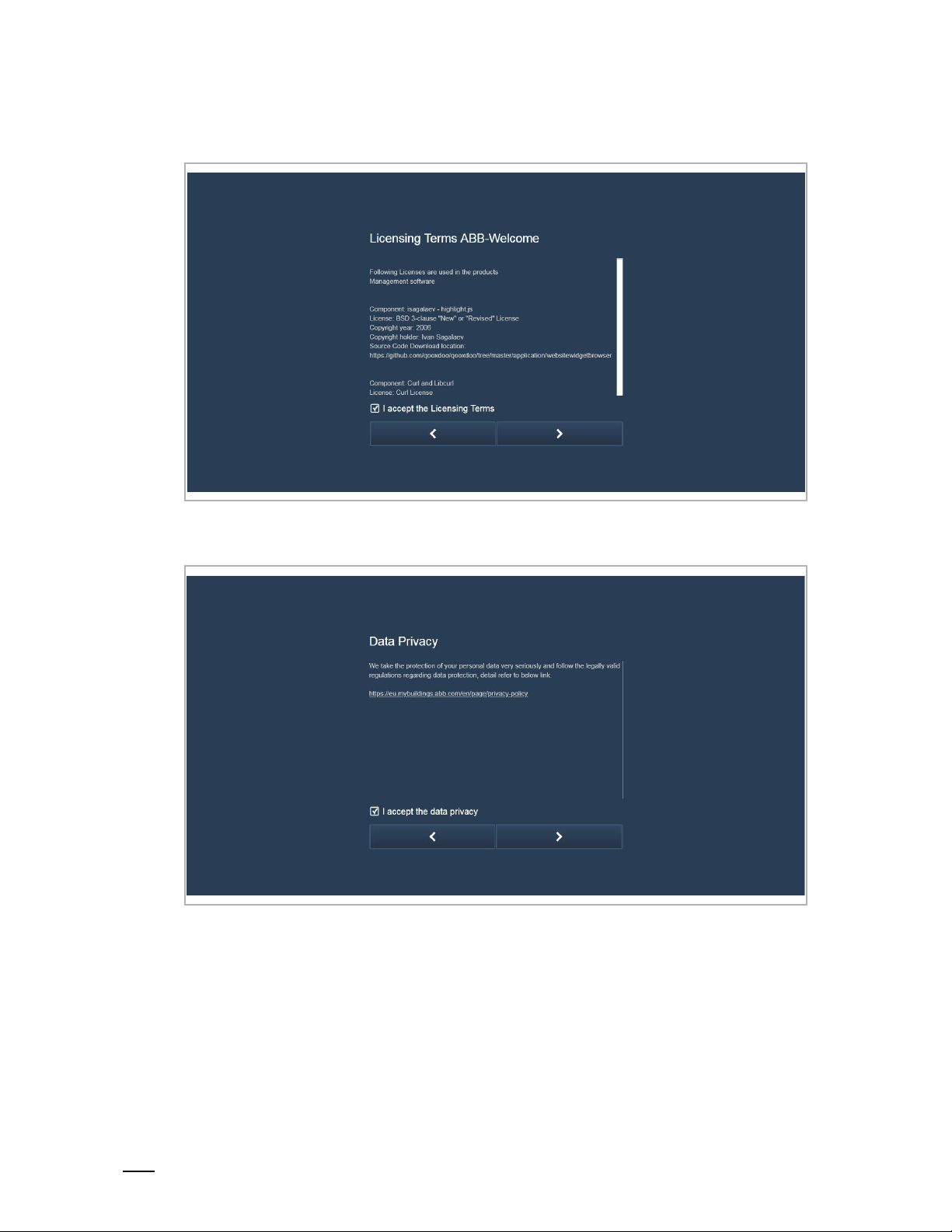
3. Smart Access Point initial setup
Enter the URL "192.168.3.1" to access Smart Access Point.
[1] Choose language
[2] Accept end user license
Page 13
Commissioning
Product manual
2TMD041800D0022
│
13
[3] Accept OSS license
[4] Accept data privacy
Page 14
Commissioning
Product manual
2TMD041800D0022
│
14
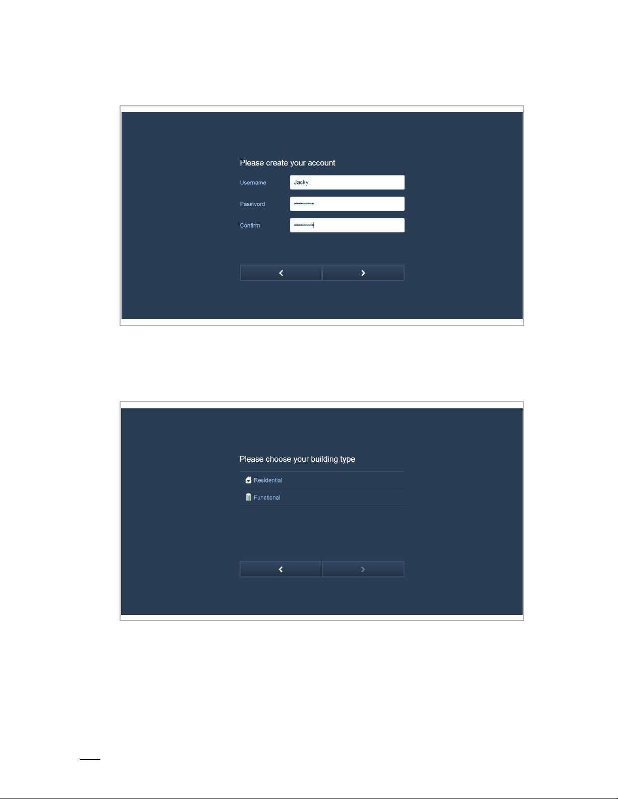
[5] Create an account
[6] Choose building type
"Functional" is selected when Smart Access Point is being used on a public network;
"Residential" is selected when Smart Access Point is being used on a home network.
Page 15
Commissioning
Product manual
2TMD041800D0022
│
15
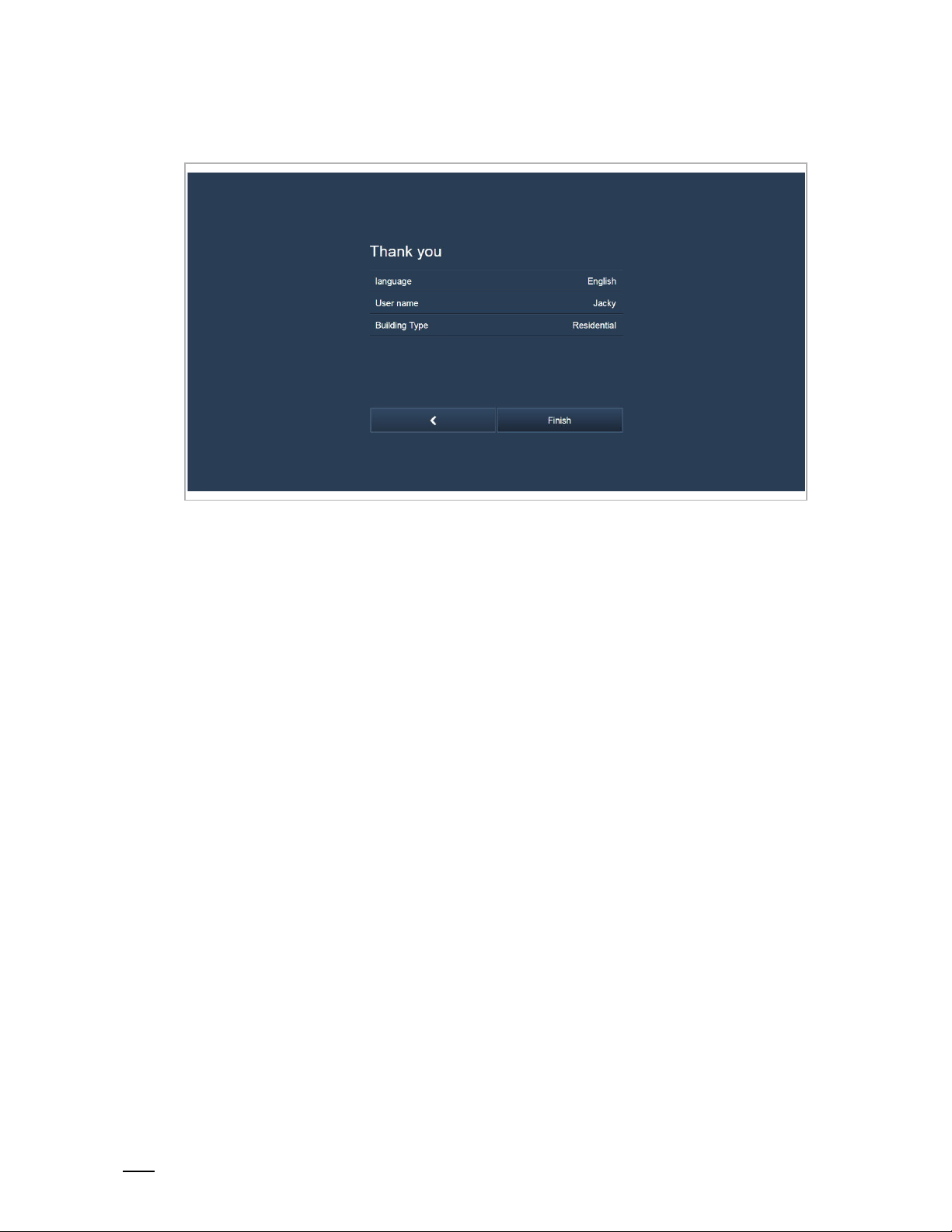
[7] Check the settings
Page 16
Commissioning
Product manual
2TMD041800D0022
│
16
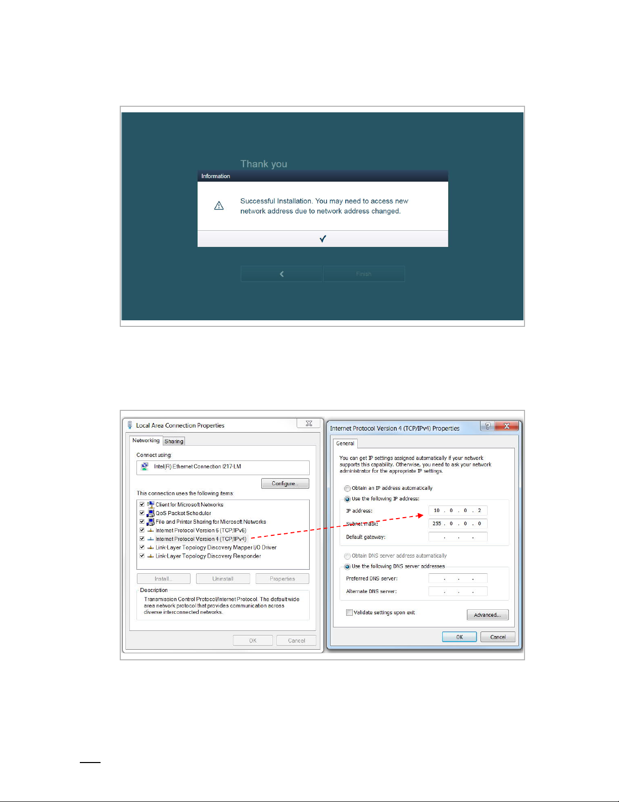
[8] Accessing Smart Access Point using a new IP address
Building type = Functional
With this setting, the IP address of Smart Access Point is set to 10.0.0.1. The IP address of the
PC must be set to the same network with Smart Access Point (e.g. 10.0.0.2).
Enter URL "10.0.0.1" to access Smart Access Point.
Page 17
Commissioning
Product manual
2TMD041800D0022
│
17
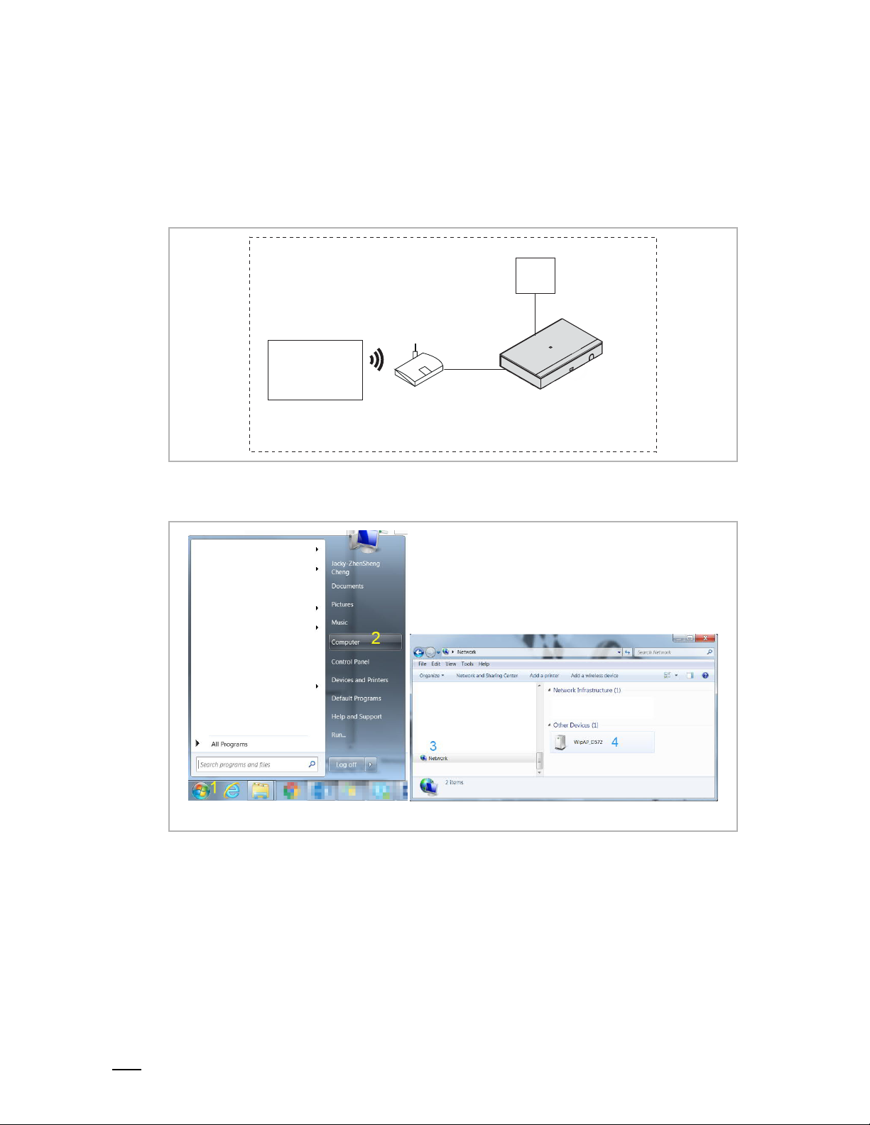
Building type = Residential
With this setting, the IP address of Smart Access Point is set to DHCP by default to obtain the
IP address from the router.
If you want to access Smart Access Point via UpnP, you need to connect the device according
the diagram below.
Home
PS
PC
Router
On the PC, you can now access Smart Access Point by following the steps below.
Smart Access Point (Residential)
Page 18
Commissioning
Product manual
2TMD041800D0022
│
18
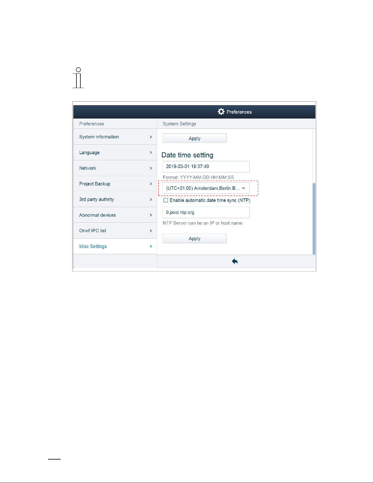
[9] Set the time zone
Note
When you access Smart Access Point for the first time, you must set the time
zone! The system default is "UTC +01:00". The system will issue a prompt if the
time in Smart Access Point is different from that of PC.
Please see the "Time setting" chapter for more details.
Page 19

Commissioning
Product manual
2TMD041800D0022
│
19
8.2 Main menu
No. Function
Notification
1
View call records, unlock records, alarm records and device fault message.
Please see the "Notification" chapter for more details.
Message center
2
Manage the messages between the indoor stations and Smart Access Point.
Please see the "Message center" chapter for more details.
Emergency unlock
3
Click the icon to release all the locks in the event of an emergency.
Please see the "Emergency unlock" chapter for more details.
Searching the devices
4
Click the icon to search all devices on the same network automatically.
Please see the "Add the devices" chapter for more details.
Import building structure
5
Click the icon to import the building structure from APP to Smart Access Point.
Please see the "Add the devices" chapter for more details.
User management
6
Manage the users in the system.
Please see the "User management" chapter for more details.
Device management
7
Manage the devices in the system.
Please see the "Device management" chapter for more details.
Logout
8
Click here to log out from the user account or change the user password.
Preferences
9
Please see the "Preferences" chapter for more details.
Page 20
Commissioning
Product manual
2TMD041800D0022
│
20
8.3 Preferences
8.3.1 Entering the settings
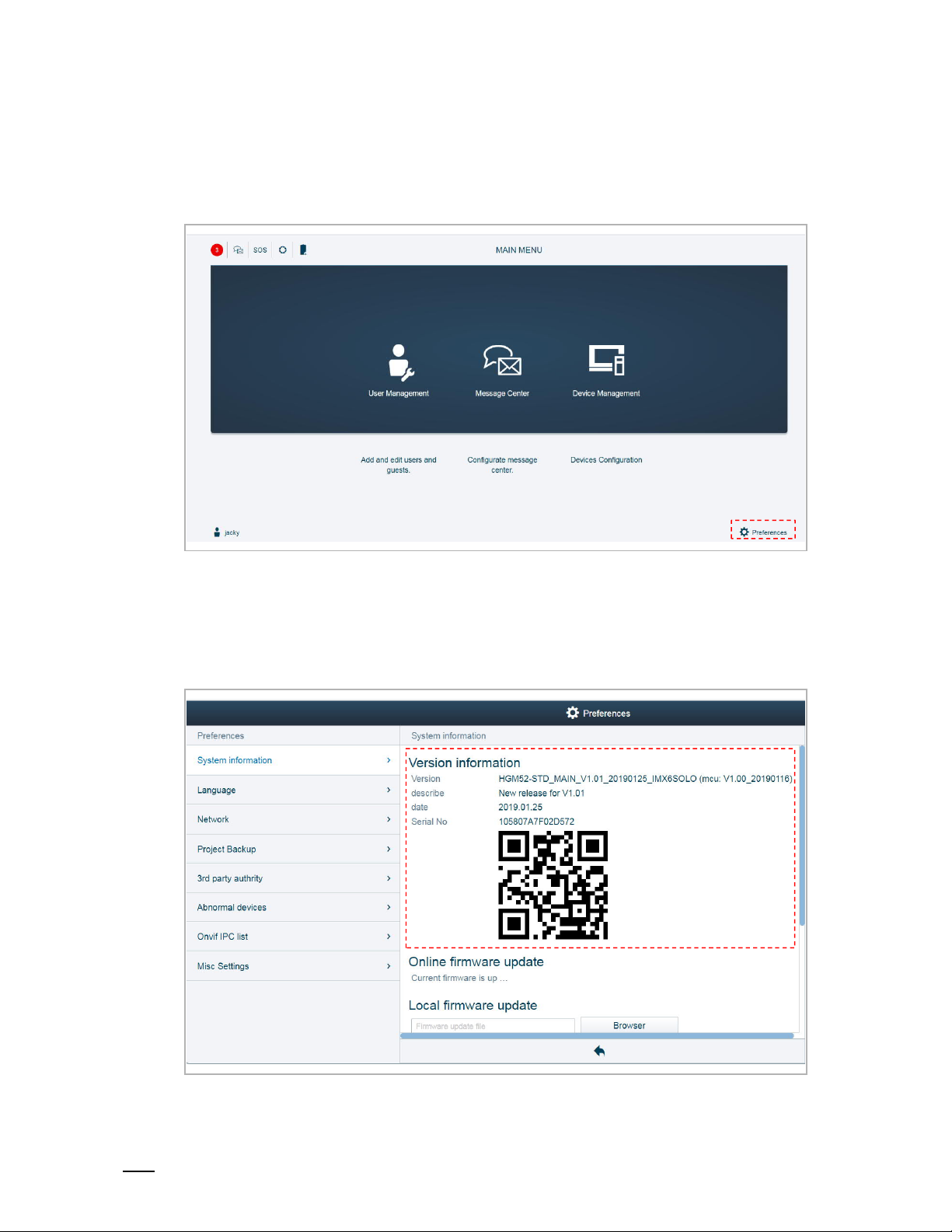
On the "MAIN MENU" screen, click "Preferences" to enter the settings.
8.3.2 View the version information
On the "Preferences", "System information" screen, you can view the version information and
serial number of Smart Access Point.
You can also use the APP to scan the QR code to obtain the serial number quickly.
Page 21

Commissioning
Product manual
2TMD041800D0022
│
21
8.3.3 Local firmware update
On the "Preferences", "System information" screen, click "Browser" and select the update file
and the signature file from the PC, then click "Update" to update the firmware.
Page 22
Commissioning
Product manual
2TMD041800D0022
│
22
8.3.4 Online firmware update
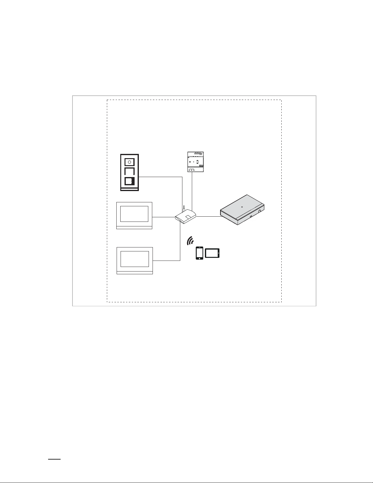
Preparation
The router must connect to the internet before use (see the diagram below).
[1] Building type = residential
Home
IP pushbutton OS
Master
IP touch 7
Slave
IP touch 7
IP actuator
Router
Smart Access Point (Residential)
APP (Residential)
Page 23
Commissioning
Product manual
2TMD041800D0022
│
23
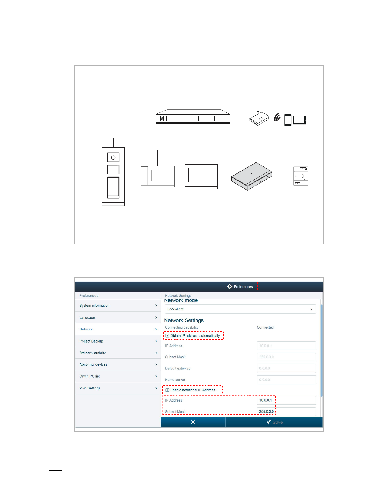
[2] Building type = functional
Community
IP touch 5 OS
Switch
Guard unit IP touch 7
APP (Functional)
10.0.0.x
255.0.0.0
Router
IP actuator
Smart Access Point (Functional)
10.0.0.1
255.0.0.0
With this setting, you needed to set additional IP address on Smart Access Point.
On the "Preference" screen, click "Network", tick "Obtain IP address automatically" and "Enable
additional IP address" and enter the data according to the image below.
Page 24

Co
mmissioning
Product manual
2TMD041800D0022
│
24
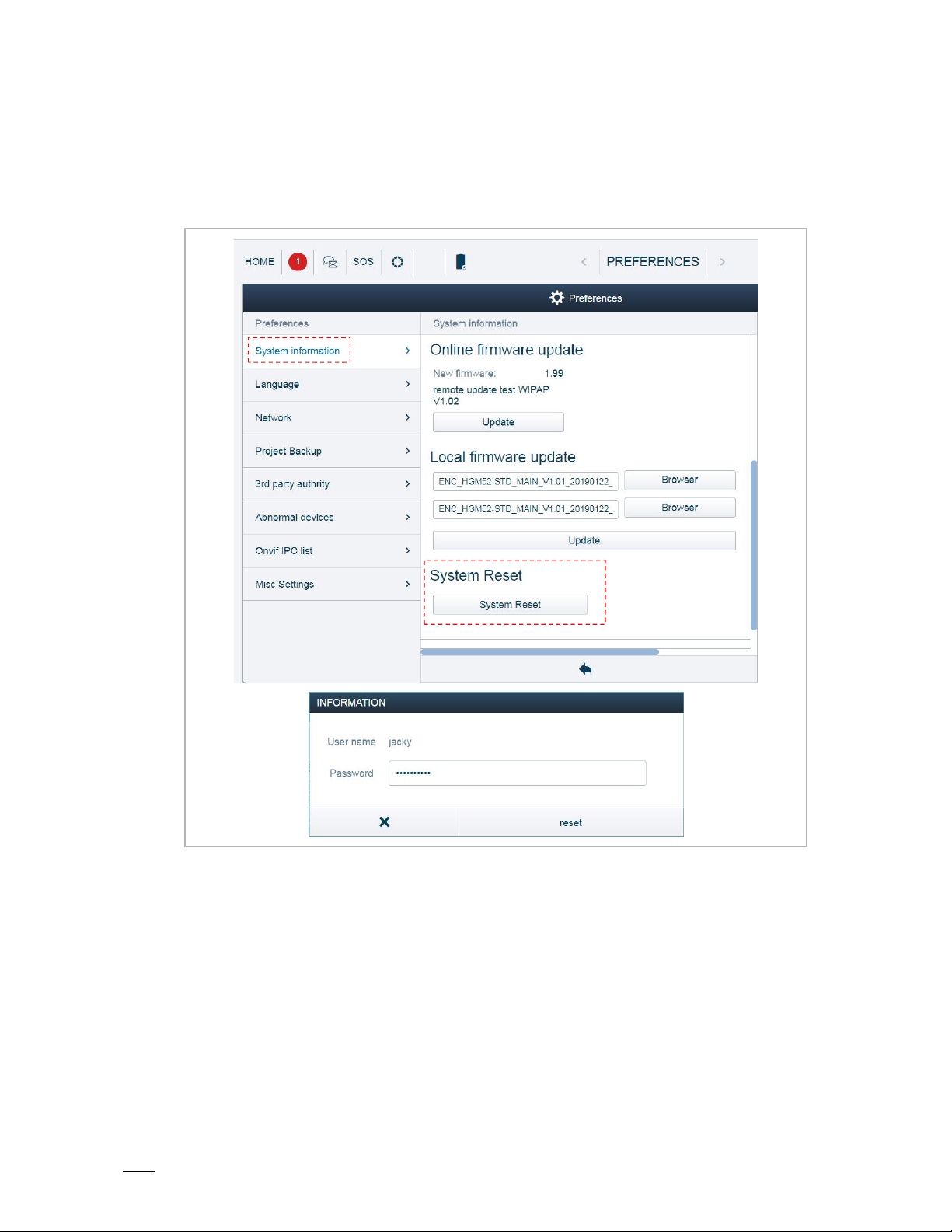
Online firmware update
On the "Preferences", "System information" screen, click "Update" to update the firmware from
the website.
Page 25
Commissioning
Product manual
2TMD041800D0022
│
25
8.3.5 Reset to factory defaults
On the "Preferences", "System information" screen, click "System Reset", and enter the user
password to reset Smart Access Point. Smart Access Point will run in AP mode by default (LED
red light is always on).
Page 26
Commissioning
Product manual
2TMD041800D0022
│
26
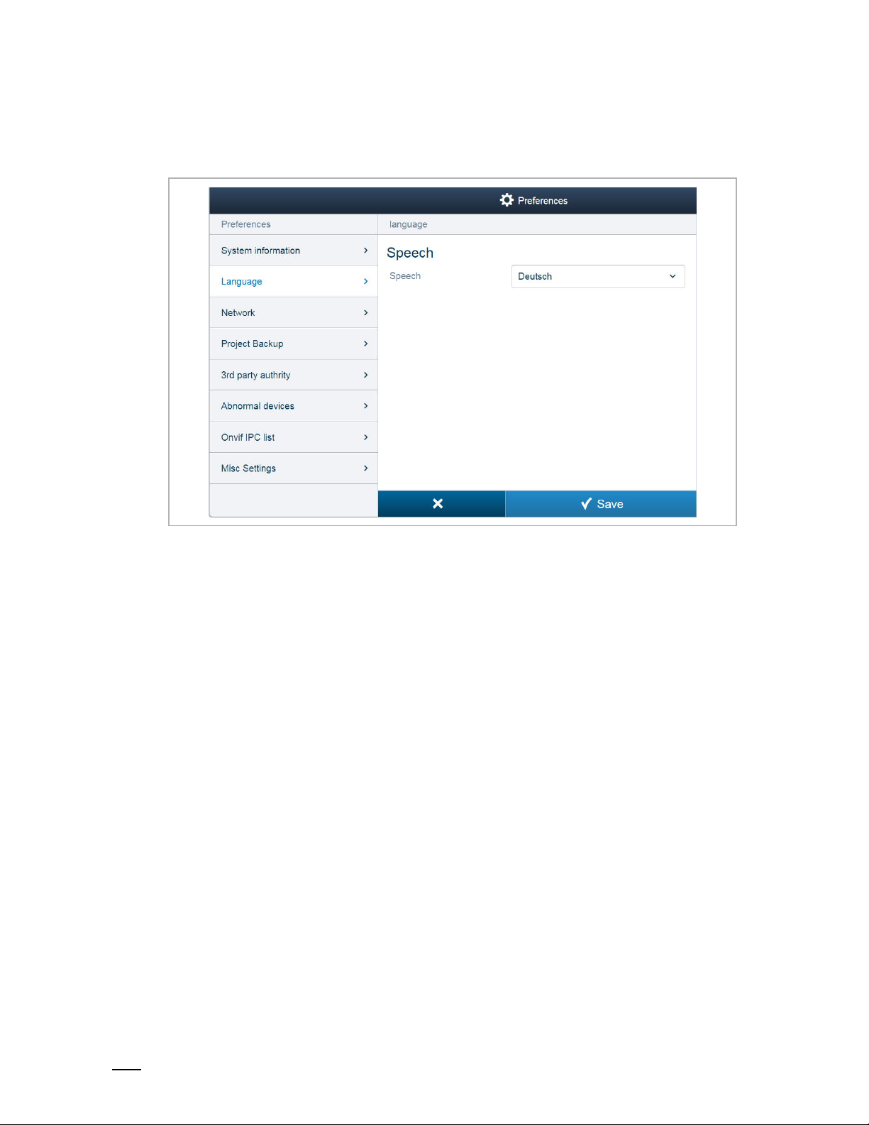
8.3.6 Language
On the "Preferences", "Language" screen, select the language from the drop-down list.
Page 27
Commissioning
Product manual
2TMD041800D0022
│
27
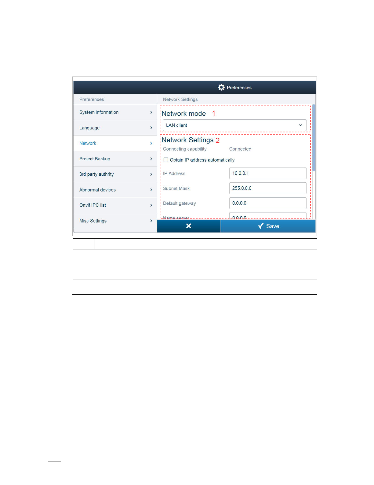
8.3.7 Network settings
On the "Preferences", "Network" screen.
No. Function
Network mode
1
(1) LAN client, if Smart Access Point connects to the router via LAN
(2) WLAN client, if Smart Access Point connects to the router via Wifi
(3) WLAN AP, if Smart Access Point is running in "AP mode"
2
Network settings
Please see the "Online firmware update" chapter for more details.
Page 28
Commissioning
Product manual
2TMD041800D0022
│
28
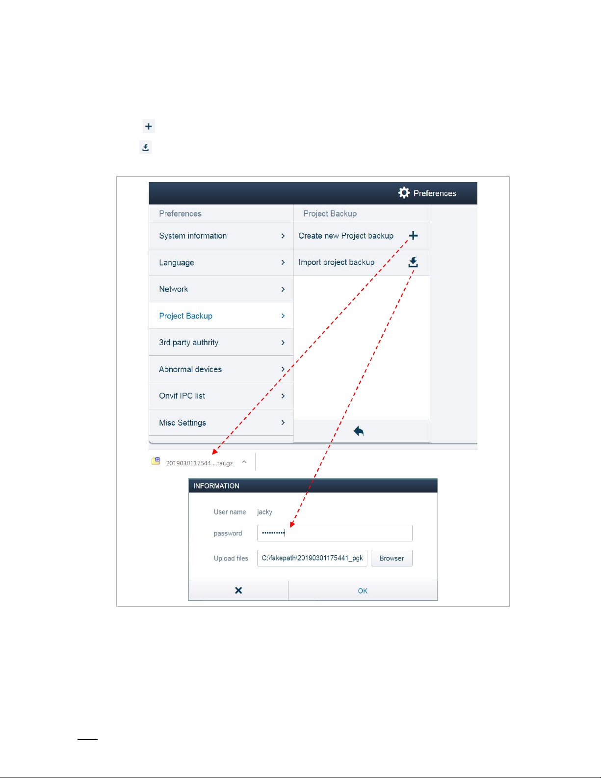
8.3.8 Backup and restore the project
On the "Preferences", "Project Backup" screen,
Click " " to create a backup onto the local PC automatically.
Click to restore the backup (the user password is required). The system will restart when
the database has been restored.
Page 29
Commissioning
Product manual
2TMD041800D0022
│
29
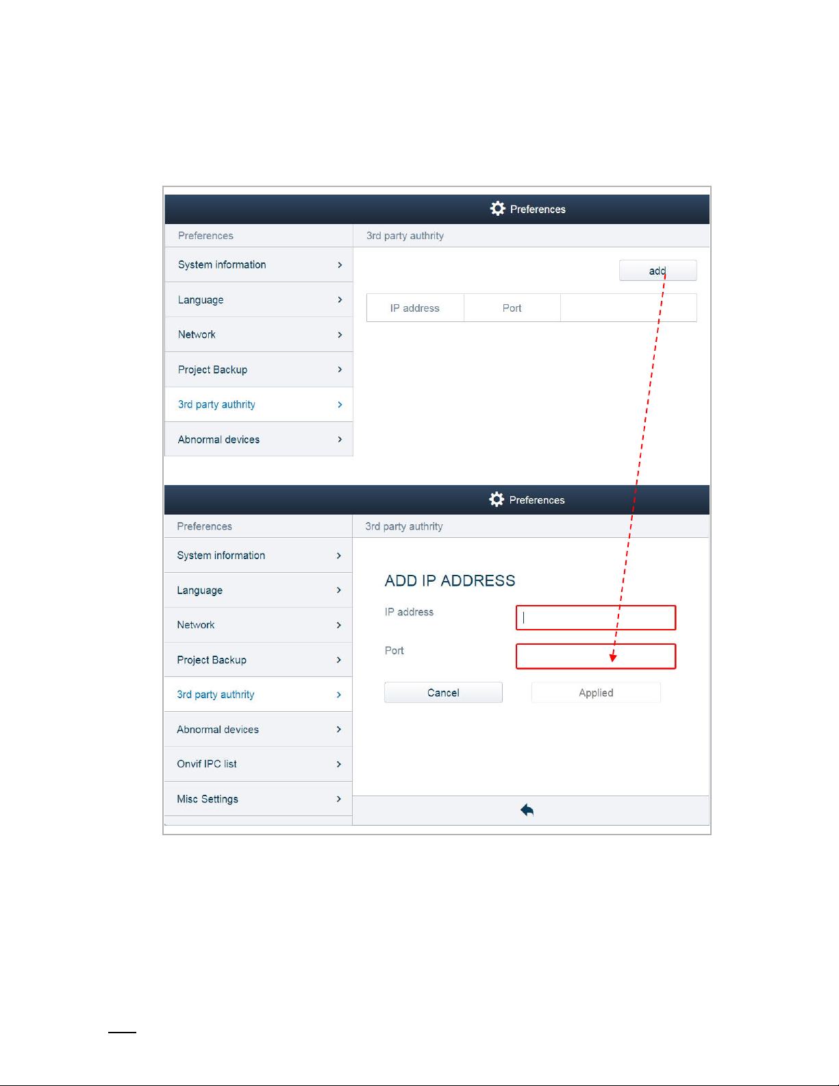
8.3.9 3rd party authority
On the "Preferences", "3rd party authority" screen, click "add" and enter the IP address and the
port number, then click "Applied" to apply the setting.
Page 30
Commissioning
Product manual
2TMD041800D0022
│
30
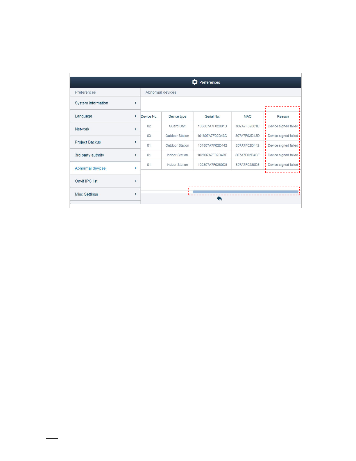
8.3.10 Check abnormal devices
On the "Preferences", "Abnormal devices" screen, you can view the error description.
Page 31

Commissioning
Product manual
2TMD041800D0022
│
31
8.3.11 Searching the Onvif IPC
On the "Preferences", "Onvif IPC list" screen, click "Search device" to search the cameras used
for the public network.
Then click "Enter credentials".
Page 32

Commissioning
Product manual
2TMD041800D0022
│
32
Enter the user name and the password of the camera, then click "Pair".
Next, you need to download the list onto the indoor station. Please see the "Community
monitor" chapter in the product manual for IP touch 7.
Lastly, you can view the camera in the drop-down list during the surveillance operation.
Page 33

Commissioning
Product manual
2TMD041800D0022
│
33
8.3.12 Time settings
On the "Preferences", "Misc Settings" screen, you can set the date and time manually or tick the
checkbox "NTP" to synchronize the date and time with NTP server.
Page 34

Commissioning
Product manual
2TMD041800D0022
│
34
8.3.13 Sync time with other devices
On the "Preferences", "Misc Settings" screen, Smart Access Point can only snyc its time with
the other devices when time synchronizaiton "Automatically" is set on Smart Access Point and
the function "Sync with management software" is enabled on the devices.
Page 35

Commissioning
Product manual
2TMD041800D0022
│
35
8.3.14 Offline alarm settings
On the "Preferences", "Misc Settings" screen, the sound notification and popup notification are
only available when the "Alarm when devices goes offline" function is enabled.
Please see the "Notification" chapter for more details.
Note
The alarm is reported via outdoor station 1 (device ID=1) or via gate station 1
(device ID=1). If either of these two devices cannot be detected in the system,
the alarm cannot be reported to Smart Access Point successfully.
When an alarm is triggered (e.g. SOS), a pop-up window appears and you can set the alarm
type (e.g. Processed) and add the comments.
Page 36

Commissioning
Product manual
2TMD041800D0022
│
36
Page 37

Operation
Product manual
2TMD041800D0022
│
37
9 Operation
9.1 Deivce management
9.1.1 Adding devices
Note
Only a device without a certificate can be added by Smart Access Point.
The device will lose its certificate if its physical address is changed.
There are 3 methods to add the devices to Smart Access Point.
Method 1: Search the devices automatically
All the devices need to be set to the physical address locally before being added.
On the "MAIN MENU" screen, click , "√" to search all devices in the same network.
If the device has already been added by this Smart Access Point, it will be ignored.
If the device has already been added by another Smart Access Point, it will appear on the
"Abnormal devices".
Please refer to the "Check abnormal devices" chapter.
Page 38

Operation
Product manual
2TMD041800D0022
│
38
Method 2: Add the devices manually
On the "MAIN MENU" screen, click "Device Management", "Add device", select the device type
(e.g. gate station) and enter the address ID and serial number of the device.
Method 3: Import the devices from APP
Please see the APP product manual for more details.
Page 39

Operation
Product manual
2TMD041800D0022
│
39
There are 4 scenarios for Smart Access Point application:
Scenario1: Adding home devices to the home Smart Access Point
■
All the devices need tobe powered on before being added
■
All 3 methods above can be used in this scenario
■
Home Smart Access Point can manage all home devices
Home
IP pushbutton OS
Master
IP touch 7
Slave
IP touch 7
IP actuator
Router
Smart Access Point (Residential)
APP (Residential)
Page 40

Operation
Product manual
2TMD041800D0022
│
40
Scenario2: Adding public devices to the public Smart Access Point
■
All the devices need tobe powered on before being added
■
All 3 methods can be used in this scenario
■
The mobile or tablet used to import the devices to Smart Access Point must be on the same
network as public Smart Access Point. (e.g. 10.0.0.x)
■
Public Smart Access Point can manage all public devices
Community
APP (Functional)
10.0.0.x
255.0.0.0
IP actuator
IP touch 5 OS
Switch
Guard unit IP touch 7
Router
Smart Access Point (Functional)
10.0.0.1
255.0.0.0
Page 41

Operation
Product manual
2TMD041800D0022
│
41
Scenario3: Add the home devices to the public Smart Access Point
■
All the devices need tobe powered on before being added
■
Public Smart Access Point can not search home devices directly due to different netwoks
■
Public Smart Access Point can add home devices via method2 or method3
■
The mobile or tablet used to import the devices to Smart Access Point must be on the same
network as publice Smart Access Point. (e.g. 10.0.0.x)
■
Public Smart Access Point can manage all public devices and home devices
Community
IP touch 5 OS
Guard unit
Switch
Smart Access Point (Functional)
10.0.0.1
255.0.0.0
Router
APP (Functional)
10.0.0.x
255.0.0.0
Home
IP pushbutton OS
IP touch 7
IP actuator
Router
Page 42

Operation
Product manual
2TMD041800D0022
│
42
Scenario4: Adding the home Smart Access Point to the public Smart Access Point
■
Home Smart Access Point can be added to Public Smart Access Point using method2
■
Public Smart Access Point can manage all public devices
■
Public Smart Access Point and home Smart Access Point can both manage all home
devices
■
If you want the home devices to be managed by the home Smart Access Point only, disable
the "Romote setting" function on the master indoor station. Please see the product manual
for IP touch 7" for more detials.
Community
IP touch 5 OS
Guard unit
Switch
Smart Access Point (Functional)
10.0.0.1
255.0.0.0
Router
APP (Functional)
10.0.0.x
255.0.0.0
Home
IP pushbutton OS
IP touch 7
IP actuator
Router
Smart Access Point (Residential)
Page 43

Operation
Product manual
2TMD041800D0022
│
43
9.1.2 Changing the settings of the devices
1. Changing the settings on one device
On the "DEVICE MANAGEMENT" screen, click a device type (e.g. "Indoor Station") and then
click a deivce (e.g. "Indoor Station 001-01010-01") to enter the settings.
Page 44

Operation
Product manual
2TMD041800D0022
│
44
2. Change the settings of several devices
You can change the settings for multiple devices at the same time.
Fox example, on the "Indoor Stations" screen, click , click the devices directly or click "select
all" to select all the devices, then click "Next".
Page 45

Operation
Product manual
2TMD041800D0022
│
45
Click "Local firmware update" to update the firmaware for these devices.
Click "Screensaver" to upload a screensave image for these devices.
Page 46

Operation
Product manual
2TMD041800D0022
│
46
9.1.3 Deleting devices
You can delete a device or multiple devices at the same time.
Fox example, on the "Outdoor Stations" screen, click , click the devices directly or click
"select all" to select all the devices, then click "Delete".
Page 47

Operation
Product manual
2TMD041800D0022
│
47
9.1.4 Set the indoor station
On the "MAIN MENU" screen, click "Device Management", " Indoor Stations", then click an
indoor station to access the settings.
Page 48

Operation
Product manual
2TMD041800D0022
│
48
Basic information
No. Function
1 Device ID
2 Click the icon to return to the previous screen
3 Overview of the indoor station
4 Display the physical address of the indoor station
5 Display the logical address of the indoor station
6 Display the first name and last name of the resident
7 Display the serial number of the indoor station
8 Display the version of the indoor station
Page 49

Operation
Product manual
2TMD041800D0022
│
49
Addtional settings
No. Funciton
1 Set the physical address of the indoor station
2 Set the logic address of the indoor station
(1)
3
4
5
Duplicate the settings to another indoor station
(2)
Update the firmware via local PC
(3)
Update the firmware via the external website
6 Set the resident data
(4)
7
8
9
Upload a screensave image to the indoor station
(5)
Upload a floorplan to the indoor station
(6)
Set the language of the indoor station
Page 50

Operation
Product manual
2TMD041800D0022
│
50
(1)
Duplicating the settings on another indoor station
Select the indoor stations and the settings to be duplicated, clice "Save" to duplicate the settings
from the current indoor station to the designated indoor stations.
(2)
Updating the firmware via local PC
Click "Browser" and select the update file and the signature file form local PC, then click "Save"
to update the firmware.
Page 51

Operation
Product manual
2TMD041800D0022
│
51
(3)
Updating the firmware via an external website
The routher must be connected to the internet before use (see the diagram below).
[1] Building type = residential
Home
IP pushbutton OS
Master
IP touch 7
Slave
IP touch 7
IP actuator
Router
Smart Access Point (Residential)
APP (Residential)
Page 52

Operation
Product manual
2TMD041800D0022
│
52
[2] Building type = functional
The routher must be connected to the internet before use (see the diagram below).
Community
APP (Functional)
Switch
Router
Guard unit IP touch 7
IP touch 5 OS
Smart Access Point (Functional)
10.0.0.1
255.0.0.0
10.0.0.x
255.0.0.0
IP actuator
In this scenario, Smart Access Point must set the additional IP address.
On the "MAIN MENU" screen, click "Preferences".
Page 53

Operation
Product manual
2TMD041800D0022
│
53
Click "Network", and set the settings accroding to the image below.
Back on the indoor staiton screen, click "Online firmware update", Smart Access Point will
search the latest version automatically. Click "Save" to update the firmware.
Page 54

Operation
Product manual
2TMD041800D0022
│
54
(4)
Upload a screensave image
Click "Browser" and select an image (.jpg is supported only, maximum resolution of the image is
1024 x 600 pixels), click "Save" to send this image to the indoor station.
(5)
Upload a floor plan
Click "Browser" to select a floorplan image (.jpg is supported only, maximum resolution of the
image is 1024 x 600 pixels), click "Save" to upload the floorplan.
Page 55

Operation
Product manual
2TMD041800D0022
│
55
(6)
Setting the language
Select the language form the drop-down list, then click "Save" to save the setting.
Page 56

Operation
Product manual
2TMD041800D0022
│
56
9.1.5 Set the outdoor station
On the "MAIN MENU" screen, click "Device Management", " Outdoor Stations", then click an
outdoor station to access the settings.
Page 57

Operation
Product manual
2TMD041800D0022
│
57
Basic information
No. Function
1 Device ID
2 Click the icon to return to the previous screen
3 Overview of the outdoor station
4 Device type of the outdoor station
5 Display the address of the outdoor station
6 Display the serial number of the outdoor station
7 Display the version of the outdoor station
Page 58

Operation
Product manual
2TMD041800D0022
│
58
Addtional settings
No. Funciton
1 Set the physical address for the outdoor station
(1)
2
3
4
5 Set the time synchronization from the management software for the outdoor station
Set the calling type for the outdoor station, please see the "Set the calling type" chapter for
more details.
(2)
Set the welcome message for the outdoor station
(3)
Set the door lock time for the outdoor station, please seeo the "Set the door lock time" chapter
for more details.
6 Set the lift control function for the outdoor station
7 Set the language for the outdoor station
Update the firmware via local PC, please refer to the "Set the indoor station" chapter for more
8
details.
Update the firmware via the external website, please refer to the "Set the indoor station" chapter
9
for more details.
(4)
10
11
12
Set the trusted devices for the outdoor station, please see the "Set the trusted devices"
chapter for more details.
(5)
Set the welcome screen for the outdoor station, please see the "Set the welcome screen"
chapter for more details.
(6)
Manage the name list, please see the "Manage the name list" chapter for more details.
Page 59

Operation
Product manual
2TMD041800D0022
│
59
(1)
Set the calling type
Tick the "Name list" checkbox, the outdoor station will start a call via the name list.
Untick the "Name list" checkbox, the outdoor station will start a call via the keypad. Next, you
can select "Physical address" or "Logical address" from the drop-down list.
(2)
Set the welcome message
Enter the text and click "Save", and the setting will be reflected on the screen of the outdoor
station.
Page 60

Operation
Product manual
2TMD041800D0022
│
60
(3)
Set the door lock time
It the default lock type is set to "IP actuator", you need to add the outdoor station to the trusted
list of IP actuators. Please see the "Set the IP actuator" chapter for more details.
Page 61

Operation
Product manual
2TMD041800D0022
│
61
(4)
Set the trusted devices
You need to enable the "Trust this management softeware" function if you want this outdoor
station to unlock in the event of an emergency. Please see the "Emergency unlock" chapter for
more details.
Click "Add trusted devices" to add the devices to the outdoor station.
For exmplae, you want the guard unit and the indoor stations to release the lock of this outdoor
station, you need to add them to the trusted list.
Page 62
Operation
Product manual
2TMD041800D0022
│
62
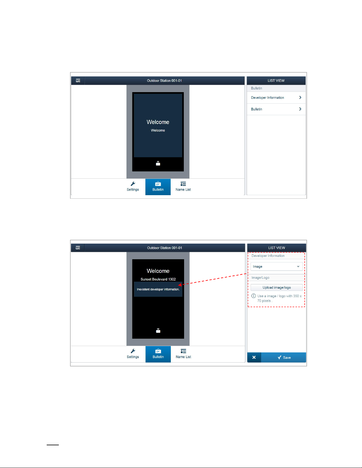
(5)
Set the welcome screen
There are 2 functions for setting the welcome screen.
[1] Developer information
Click "Development information", select an image or enter the words. The result will be
displayed on the screen of the outdoor station.
Page 63

Operation
Product manual
2TMD041800D0022
│
63
[2] Bulletin
Click "Bulletin", "Add bulletin page", "Upload image/logo" to upload a logo or a word. This logo
or word will be displayed on the screen of the outdoor station.
A maximum of 3 bulletins can be uploaded. The outdoor station plays the bulletins one by one
and each bulletin is displayed 10 s.
Page 64

Operation
Product manual
2TMD041800D0022
│
64
(6)
Manage the name list
1. Add the name list
There are 2 ways to add the name list
Method 1: Import the name list from another outdoor station
Click "Import name list entries" and select the another outdoor station. Then click "import" to
import the name list from another outdoor station.
Page 65

Operation
Product manual
2TMD041800D0022
│
65
Method 2: Add the name list on Smart Access Point
Click "Add item", enter the resident information, upload the image as and assign the indoor
staitons to the user, click "Save" and select the another outdoor station. Then click "import" to
import the name list from another outdoor station.
Page 66

Operation
Product manual
2TMD041800D0022
│
66
2. Copy the name list to the other outdoor station
Click "Copy name list to other OS", select the destination outdoor stations, click "Import".
3. Remove the name list
Click "Remove all entries", then click "Continue" to clear the name list.
Page 67

Operation
Product manual
2TMD041800D0022
│
67
Design label
The function is for IP pushbutton outdoor station only.
Access the settings screen of IP pushbutton outdoor station first, then click "Design lable".
There are a lot of setting items for designing the lable. When you complete the design, click
"Print" to pirnt it.
Page 68

Operation
Product manual
2TMD041800D0022
│
68
9.1.6 Set the guard unit
On the "MAIN MENU" screen, click "Device Management", "Guard unit".
On the "GUARD UNIT" screen, click a guard unit to access the settings.
Page 69

Operation
Product manual
2TMD041800D0022
│
69
No. Function
1 Device ID
2 Click the icon to return to the previous screen
3 Overview of the guard unit
4 Device number of the guard unit
5 Display the serial number of the guard unit
6 Display the version of the guard unit
Update the firmware via local PC, please refer to the "Set the indoor station" chapter for more
7
details.
Update the firmware via the external website, please refer to the "Set the indoor station" chapter
8
for more details.
Page 70

Operation
Product manual
2TMD041800D0022
│
70
9.1.7 Set the IP actuator
On the "MAIN MENU" screen, click "Device Management", " IP actuator".
On the "IP ACTATOR" screen, click a IP actuator to access the settings screen.
Page 71

Operation
Product manual
2TMD041800D0022
│
71
No. Function
1 Device ID
2 Click the icon to return to the previous screen
3 Overview of the IP actuator
4 Set device type of the IP actuator (e.g. network IPA, building IPA and private IPA)
5 Display the physical address of the IP actuator
6 Display the serial number of the IP actuator
7 Display the version of the IP actuator
(1)
8
9
10
11
Set the lock connected to the IP actuator
Update the firmware via local PC, please refer to the "Set the indoor station" chapter for more
details.
Update the firmware via the external website, please refer to the "Set the indoor station" chapter
for more details.
(2)
Set trusted devices for the IP actuator
Page 72

Operation
Product manual
2TMD041800D0022
│
72
(1)
Set the lock connected to the IP actuator
Page 73

Operation
Product manual
2TMD041800D0022
│
73
(2)
Set the trusted devices for the IP actuator
You need to enable the "Trust this management softeware" function if you want this IP actuator
to unlock in the event of an emergency. Please see the "Emergency unlock" chapter for more
details.
Click "Add trusted devices" to add the devices to the IP actuator.
For exmplae, you want the guard unit and the indoor stations to release the lock of this IP
actuator, you need to add them to the trusted list.
Page 74

Operation
Product manual
2TMD041800D0022
│
74
Release the IP actuator connected to the outdoor station
If the default lock type of the outdoor station is set to "IP actuator", you need to select an IP
actuator.
This outdoor staiton must be added to the trusted list of IP actuator in advance.
Page 75

Operation
Product manual
2TMD041800D0022
│
75
9.2 User management
9.2.1 Enter the settings screen
On the "MAIN MENU" screen, click "User Management" to access the settings.
Page 76
Operation
Product manual
2TMD041800D0022
│
76
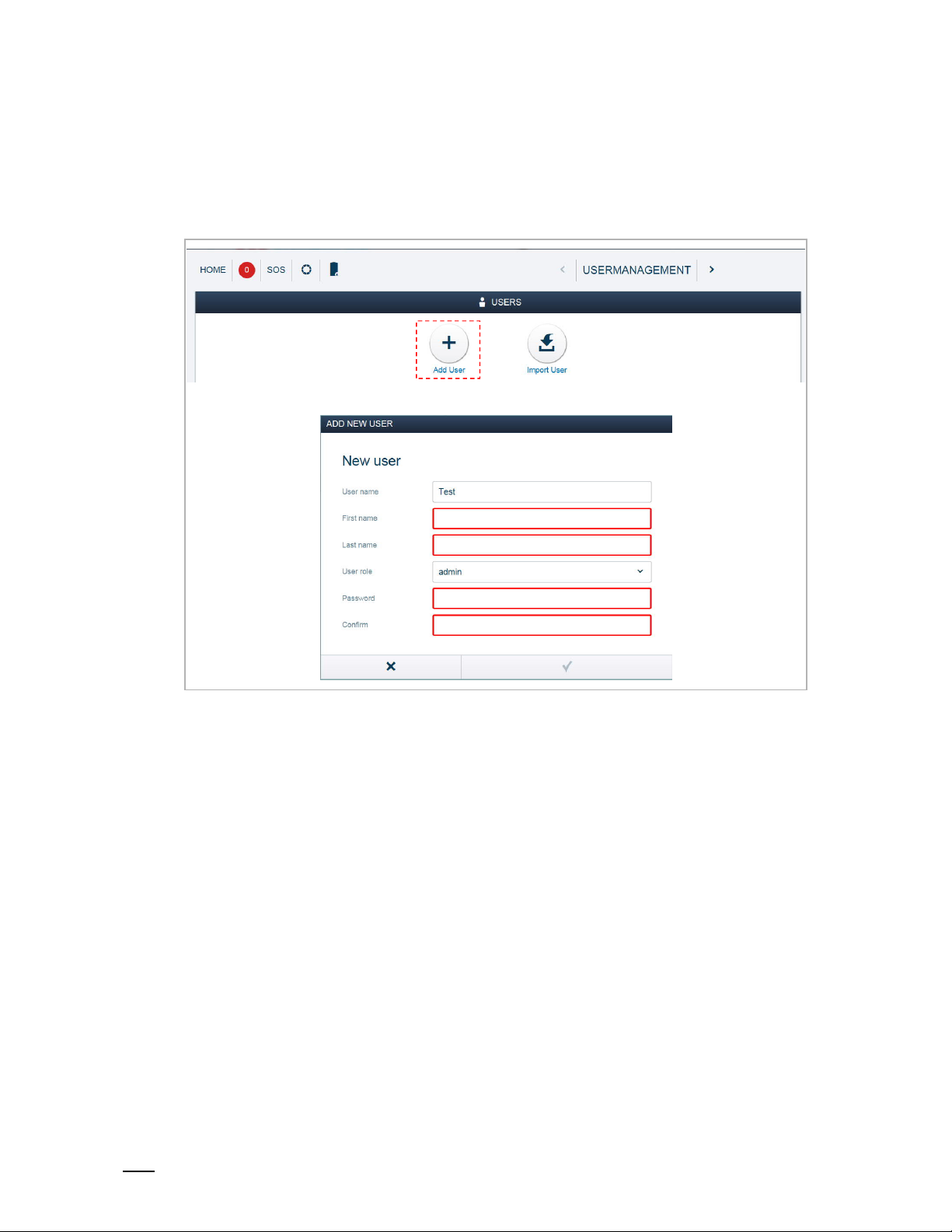
9.2.2 Adding users one by one
On the "USER MANAGEMENT" screen, click "Add user", select the user role (e.g. admin), enter
the user name, first name, last name etc., click "√" to add a user.
A maximum of 2000 users can be added on the system.
Page 77

Operation
Product manual
2TMD041800D0022
│
77
9.2.3 Importing the users via a template
On the "USER MANAGEMENT" screen, click "Import user", "Download user’s template" to
download a CSV file named "user_template.csv" to the local PC.
Open the CSV file and enter the data.
*Card number
If multiple cards are used in the same apartment, they should be entered on different lines.
Maximum length of card nunmer is 10 digits.
*Lift control
Different floors numbers must be separated with ".";
Enter "All" if all floors are used. Leave blank if no floor is used.
Page 78

Operation
Product manual
2TMD041800D0022
│
78
Click "Browser" and select the CSV file, click "√" to import the data to the system.
Page 79

Operation
Product manual
2TMD041800D0022
│
79
9.2.4 Assign the deives to the user
Please see the "Add the devices" chapter to add the devices to Smart Access Point before use.
On the "USERS" screen, click a user name (e.g. "jacky") to access the corresponding screen.
Page 80

Operation
Product manual
2TMD041800D0022
│
80
1. Manage the user cards
Assigning the user card to the user
On the "jacky" screen, click "User card", "Add card".
Page 81

Operation
Product manual
2TMD041800D0022
│
81
Enter the data then click "√",
No. Function
Card type
1
You can use a keycard or tag.
Validity period
2
The system default is "Unlimited validity".
If "Limited validity" is selected, you need to enter the start date and the end date.
Register type
3
If "Card no." is selected, you can enter the card number directly. (support for ID cards only)
If "Outdoor Station" is selected, the card number will be obtained from the outdoor station.
Floor no.
4
Click "+" and select the floor number (see the diagram below).
With this setting, swiping the user card provides access to the designated floor via the lift.
Page 82

Operation
Product manual
2TMD041800D0022
│
82
If "Register by" is set to "Outdoor station", you need to select an outdoor station and swip the
user card on this outdoor station when you see the "Please swipe" prompt.
A maximum of 200 user cards can be assigned to a user.
Deleting a user card from a user
On the "jacky" screen, click the user cards, then click "Delete Card", "√" to delete it.
Page 83

Operation
Product manual
2TMD041800D0022
│
83
2. Manage the indoor stations
Assigning the indoor stations to the user
On the "jacky" screen, click "Indoor Station", click an indoor station and then click "√" to add the
indoor station to the user.
Page 84

Operation
Product manual
2TMD041800D0022
│
84
Removing an indoor station from a user
On the "jacky" screen, click an indoor station on the "Assigned" section, then click "√" to remove
the indoor station from the user.
Page 85

Operation
Product manual
2TMD041800D0022
│
85
3. Manage the doors
Assign doors to a user
On the "jacky" screen, click "Doors", click an outdoor station and click "√" to add the door to the
user.
Note
The user card assigned to this user can unlock all the locks assigned to this
user. If the user card is removed from the user, it cannot unlock the locks
assigned to this user.
It is recommended that user cards are created and maintained using local
outdoor stations or management software only.
Page 86

Operation
Product manual
2TMD041800D0022
│
86
Removing doors from a user
On the "jacky" screen, click an outdoor station on "Assigned" section, then click "√" to remove
the outdoor station from the user.
Page 87

Operation
Product manual
2TMD041800D0022
│
87
9.2.5 Changing user information
On the "USERS" screen, click the username (e.g. "jacky") to access the corresponding screen.
In the "LIST VIEW", you can edait the user account or change the user password.
Page 88

Operation
Product manual
2TMD041800D0022
│
88
9.2.6 Deleting users
On the "USERS" screen, click the user name (e.g. "jacky") to access the corresponding screen.
In the "LIST VIEW", you can click , "√" to delete the user.
Note
If there is only one admin user, it cannot be deleted.
Page 89

Operation
Product manual
2TMD041800D0022
│
89
9.2.7 Logging in with different accounts
If there are no more than 5 admin users, you can click an account and enter the password to log
in.
If there are more than 5 admin users, you need to enter the account and the password to log in.
Page 90

Operation
Product manual
2TMD041800D0022
│
90
9.3 Notification
9.3.1 Enter the Settings screen
On the "MAIN MENU" screen, click to access the "Notification" screen.
Page 91

Operation
Product manual
2TMD041800D0022
│
91
9.3.2 Alarm list
On the "NOTIFICATION" screen, click "Alarm list", then click an alarm, you can change the
status and add the comments.
A maximum of 50,000 alarms is supported.
You can use the filter to view the designated alarms.
For example, tick "Today" , and click "Inquire" to view that today’s alarm records.
Page 92

Operation
Product manual
2TMD041800D0022
│
92
9.3.3 Device Fault
On the "NOTIFICATION" screen, click "Device Fault", then click an alarm. You can then change
the status and add the comments.
A maximum of 50,000 fault records is supported.
You can use the filter to view the designated fault records.
For example, tick "Today" and click "Inquire" to view that day’s fault records.
Page 93

Operation
Product manual
2TMD041800D0022
│
93
9.3.4 Call list
On the "NOTIFICATION" screen, click "Call list" to view the call records.
A maximum of 500 call records is supported.
You can use the filter to view the designated call records.
For example, tick "Today" and click "Inquire" to view that today’s call records.
Page 94

Operation
Product manual
2TMD041800D0022
│
94
9.3.5 Unlock list
On the "NOTIFICATION" screen, click "Unlock list" to view the unlock records.
A maximum of 50,000 unlock records is supported.
You can use the filter to view the designated unlock records.
For example, tick "Today" and click "Inquire" to view that day’s unlock records.
Page 95

Operation
Product manual
2TMD041800D0022
│
95
9.4 Message Center
This chapter is for functional Smart Access Point only.
On the "MAIN MENU" screen, click "Message Center" to access the corresponding screen.
Page 96

Operation
Product manual
2TMD041800D0022
│
96
9.4.1 Creating and sending a message
On the "MESSAGE CENTER" screen, click "+" to set a receiver, then enter the subject and the
message, click "√" to create and send the message.
Page 97

Operation
Product manual
2TMD041800D0022
│
97
9.4.2 Viewing and replying to messages
On the "MESSAGE CENTER" screen, click "Inbox" to view the message received from the
indoor stations. You can click a message and reply it directly.
A maximum of 1000 messages is supported.
You can use the filter to view the messages in the inbox.
For example, tick "Today" and click "Inquire" to view that day’s messages.
Page 98

Operation
Product manual
2TMD041800D0022
│
98
Your replay messages can be viewed on the "Outbox".
A maximum of 100 messages can be supported.
You can use the filter to view the messages in the outbox.
For example, tick "Today" and click "Inquire" to view that day’s messages.
Page 99

Operation
Product manual
2TMD041800D0022
│
99
9.5 Emergency unlock
Note
Smart Access Point must be added to the trusted list on the outdoor stations,
gate stations and Public IP actuators before this function is used.
On the "MAIN MENU" screen, click "SOS" and enter the user password, click "Unlock all public
doors" to release all the locks connected to the outdoor stations/gate stations and public IP
actuators.
Page 100

FCC
Product manual
2TMD041800D0022
│
100
10 FCC
FCC ID: 2AEBL-D04012
This device complies with Part 15 of the FCC Rules. Operation is subject to the following two
conditions: (1) this device may not cause harmful interference, and (2) this device must accept
any interference received, including interference that may cause undesired operation.
Only operate the device in accordance with the instructions supplied.
Changes or modifications to this unit not expressly approved by the party responsible for
compliance could void the user’s authority to operate the equipment.
This device complies with FCC radiation exposure limits set forth for an uncontrolled
environment. In order to avoid the possibility of exceeding the FCC radio frequency exposure
limits, human proximity to the antenna shall not be less than 20cm (8 inches) during normal
operation.
NOTE: This equipment has been tested and found to comply with the limits for a Class B digital
device, pursuant to part 15 of the FCC Rules. These limits are designed to provide reasonable
protection against harmful interference in a residential installation. This equipment
generates, uses and can radiate radio frequency energy and, if not installed and used in
accordance with the instructions, may cause harmful interference to radio communications.
However, there is no guarantee that interference will not occur in a particular installation. If
this equipment does cause harmful interference to radio or television reception, which can be
determined by turning the equipment off and on, the user is encouraged to try to correct the
interference by one or more of the following measures:
– Reorient or relocate the receiving antenna.
– Increase the separation between the equipment and receiver.
– Connect the equipment into an outlet on a circuit different from that to which the receiver is
connected.
– Consult the dealer or an experienced radio/TV technician for help.
 Loading...