

Page 1
ABB Automation Inc.
Substation Automation and Protection Division
ABB
ABB
ABBABB
Effective: October 1999
Supersedes I.L. 41-223L, dated January 1996
( ) Denotes Change Since Previous Issue
CAUTION
!
Before putting protective relays into service,
remove all blocking inserted for the purpose of
securing the parts during shipment. Make sure
that all moving parts operate freely. Inspect the
contacts to see that they are clean and close
properly, and operate the relay to check the settings and electrical connections.
Coral Springs, FL 33065
1.0 APPLICATIONS
The type CVQ relay prov ide s instan tan eous an d ti me
delay detection of negativ e sequence ove rvoltage as
well as responding with tim e del ay to pha se-to-phase
undervoltage.
Used in motor protecti on, the relay protects against
system undervoltage, single phasing of the supply
and reversal of phase rotation of the supply.
Instruction Leaflet
41-223N
Type CVQ Relay
If static (i.e., non motor) load i s single-phase d with a
motor or group of motors, the negative sequence voltage will be greater than the v alue calculated above.
Single phasing of a predominately static load produces 50% negative sequence voltage on the load
side of the open circuit.
When the relay i s used for overvol tage pr otec tion t he
back contacts are made at normal voltage and the
negative sequence element is committed to an
instantaneous function. The normally open E2 contact may be used for alarm purposes.
2.0 CONSTRUCTION & OPERATION
The type CVQ relay consis ts of a polar unit (E) oper ating on negative sequence quantities, a negative
sequence voltage filter, full wave bridge, a time
undervoltage relay (CV), an indicating contactor
switch (ICS) and a telep hone relay when used. The
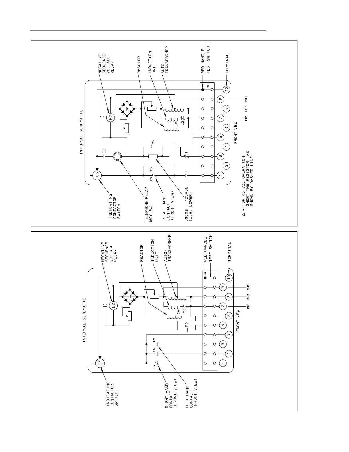
principal componen t parts of the rel ay and their lo cation are shown in Figure 1 (page 2).
The volt-time ch aracteristic of the re lay is that of the
CV-7 relay, and t he negative sequence overvolt age
pickup is adjustable from 5 to 10 percent of rated
to neutral
When one of the thre e supply circuits to a motor is
opened, a negative se quence voltage will appear on
the motor side of the open which is approximately
equal to I
current flowing pr ior to opening the phase and I
the motor starting cur rent. For mo st induc tion motor s
this will produce approximately 6% negative
sequence voltag e ev en if s in gle pha si ng o ccur s at no
load because of the effect of the magnetizing requirement of the motor.
All possible contingencies which may arise during installation, operation or maintenance, and all details and
variations of this equ ipment do not purport to be covered by these in structions. If further information is
desired by purchase r re gardi ng thi s p artic ul ar in st all ati on, ope ra tio n or maintenance of thi s equ ipment, the
local ABB Power T&D Company Inc. representative should be contacted.
Printed in U.S.A
voltage.
in per unit where IL is positive seque nc e
L/IS
.
line
S
2.1 POLAR UNIT
The polar unit consists of a recta ngular shap ed magnetic frame, an electrom agnet, a permanent m agnet,
and an armature. The pol es of the crescent shaped
permanent magnet bridge the magnetic frame. The
magnetic frame consi sts of three piece s joined in the
rear with two brass rods and silver solder. These nonmagnetic joints repres ent ai r gaps, which are br idged
by two adjustable magnetic shunts. The winding or
is
windings are wound around a magnetic core. The
armature is fastened to this core and is free to move
in the front air gap. The m oving contact is connected
to the free end of a leaf spring, which in turn, is fastened to the armature.
Page 2
41-223N CVQ Relay
880A343
*Sub 2
*Sub 4
188A644
Figure 1. Internal Schematic of the Type CVQ Relay Figure 2. Internal Schematic of Type CVQ Relay with Telephone Relay
2
Page 3

CVQ Relay 41-223N
2.2 NEGATIVE SEQUENCE FILTER
The voltage filter consists of an auto-transformer,
reactor, and resistors connected as shown in the
internal schematic Figure 1 (page 2).
2.3 VOLTAGE UNIT (CV)
The voltage unit operates on the induction-d isc principal. A main tapp ed coil l ocate d on the center l eg of
an “E” type laminated structure produces a flux which
divides and returns t hrough the right le g (front view)
to lag the main pole flux. The out-of-phase fluxes
thus produced in the air gap causes a contact closing
torque.
2.4 INDICATING CONTACTOR SWITCH (ICS)
The indicating contactor switch is a small dc operated clapper type device. A magnetic armature to
which leaf-spring mounted contacts are attached is
attracted to the magneti c core upon energization of
the switch. When th e switch closes , the mov ing contacts bridge two stati onary contacts, completing the
trip circuit. Also d uring this operation two fi ngers on
the armature deflect a spring located on the front of
the switch, which al lows the operation indicator tar get to drop. The target is reset from the outside of the
case by a push-rod located at the bottom of the case.
The front spring, in addition to holding the target, provides restraint for th e armature and thu s controls th e
pickup value of the switch.
2.5 FULL WAVE BRIDGE
and 10 percent of the rated line to neutral voltage.
Voltage Unit
which the overvoltage front contact (left-hand, front
view) closes. The undervoltage back contact (righthand, front view) will close within 5% of this value.
When used as an overvoltage relay, the movin g c ontact is initially at rest ag ai ns t the back contact for values of voltage less than tap value. With application of
overvoltage greater th an tap value, the moving contact moves to close the front contact in a time as
shown by the right-hand cur ves of F igure 3 (page 8).
When energize d and used as an under voltage relay,
the moving contact is initially at rest against the front
contact for values of voltage greater than tap value.
With the reduc tion of voltage to less than t ap value,
the moving contact m ove s to clo se the ba ck co nta ct i n
a time as shown by the left-hand curves of Figure 3.
3.1 REDUCED FREQUENCY OPERATION
Operation of the E2 unit wil l occur at approximately
54 Hz with rated positiv e sequence voltage applied
when set for 5% negative- se quen ce pic kup a t 60 Hz .
With a 10% setting, operation occurs at approximately 48 Hz.
3.2 TRIP CIRCUIT
The main contacts will safely close 30 amperes at
250 volts dc and the seal-in contacts of the indicating
contactor switch will safely carry this current long
enough to trip a circuit breaker.
— Tap value voltage is the value at
The full wave bridge consists of four diodes connected to the output o f the negative sequence f ilter.
The output is rectified, filtered and fed to the polar
unit through an adjus table resistor, which i s used to
set the sensitivity of the relay.
2.6 AUXILIARY TIME DELAY UNIT (T) – WHEN USED
This slugged telephone type unit in series with a
resistor, provides a 6 to 7 cycle delay on pick-up. The
resistor is to be shorted for 48 Vdc operation as
shown in the Internal Schematic of Figure 2 (page 2).
3.0 CHARACTERISTICS
Polar Unit
sequence portion of the relay is adjustable between 5
— The sensitivity of the negative
The indicating contactor switch has two taps that provide a pickup setting of 0 .2 o r 2 am peres . To ch ange
taps requires conne cting the lead located in front of
the tap block to the desired setting by means of a
screw connection.
3.3 TRIP CIRCUIT CONSTANTS
Indicating contactor switch – 0.2 amp tap 6.5
ohms dc resistance.
2.0 amp tap 0.15
ohms dc resistance.
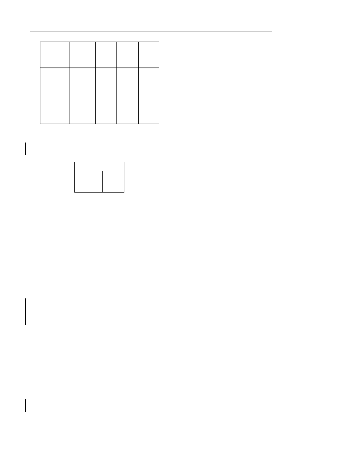
4.0 ENERGY REQUIREMENTS
The burden of the undervoltage CV unit at rated voltage are as follows:
3
Page 4
41-223N CVQ Relay
Taps
a
Rated
Voltage
120 Volts
a.
These relays will continuously withstand either 110% of
rated voltage or tap value voltage, whichever is higher
120 Vol t
Relay
55
64
70
82
93
105
120
140
Volt
Amps
10.0
7.0
5.8
4.0
3.1
2.4
1.8
1.3
Power
Factor Watts
.38
.35
.34
.33
.31
.29
.28
.26
3.8
2.5
2.0
1.3
1.0
.7
.5
.3
.
The burden of the negative sequ ence filter at rated
voltage is as follows:
Volt Amperes
Phase 1
Phase 2
Phase 3
58.4
10.5
52.2
5.0 SETTINGS
5.1 POLAR UNIT
The relay will be shipped adjusted for 5% negative
sequence sensitivity. Other settings may be made as
indicated under Section 8, “
Calibration
”.
The nylon screw o n the terminal plat e holds the tap
plate in position when taps are being changed. To
use the position on the terminal plate in which the
nylon screw is used, remove the nylon screw and
place it in one of the unus ed ho les . Then remove the
tap screw and insert it in the terminal plate hole.
5.3 MOTOR PROTECTION SETTINGS
For motor protection a tap setting of 75 to 85% of
normal line to line volt ages and a time dial setting of
6 or more should be satisfactory for protecting the
motor and overriding voltage variations for which tripping is not desired.
5.4 NEGATIVE SEQUENCE FILTER
No setting required.
5.5 INDICATING CONTACTOR SWITCH (ICS)
The only setting required on the ICS unit is the
selection of the 0.2 or 2.0 ampere tap se tting. This
selection is made by connecting the lead located in
the front of the tap block to the desired setting by
means of the connecting screw. The 0.2 ampere
setting is recommended where an au xiliary relay is
to be opera ted and the 2.0 ampere settin g is recommended where direct tripping of a circuit breaker is to
be accomplished.
5.2 CV UNIT
The setting of the CV uni t can be defined either by
tap setting and time dial position; or by tap setting
and a specific time of op eration at some pe rcentage
of tap value voltage (e.g. on CV-7 120 volt tap setting
and 2 time dial position; or 120 vo lt tap setting and
1.8 seconds at 140% of tap value volta ge). See figure 3 on page 8.
To provide selective circuit breaker operation, a minimum coordinating time of 0.3 seconds plus circuit
breaker time is recommended between the relay
being set and the relays with wh ic h c oordi nat ion is to
be effected.
The connector screw on the term inal plate abo ve the
time dial connects vari ous turns of the operati ng coil .
By placing this screw in the various terminal plate
holes, the relay will just clos e its front c ontact s at the
corresponding tap va lue of 55-64-7 0-82-93- 105-120140 volts or as marked on the terminal plate.
5.6 RESISTOR (FOR TELEPHONE RELAY)
The relay is shipped with resistor in series with telephone relay for 125 Vdc ope ration. For 48 V dc operation this resistor is to be shorted.
6.0 INSTALLATION
The relays should be mounted on switchboard p anels or their equivalent in a location free from dirt,
moisture, excessive vibration and heat. Mount the
relay vertically by means of the rear mounting stud or
studs for the type FT p rojection cas e or by m eans of
the four mounting holes on the flange for the semiflush type FT case. Eith er the stud or the mounting
screws may be ut iliz ed fo r gr oundi ng t he rel ay. Exter nal toothed washers are p r ovi de d fo r us e i n t he l ocations shown on the outline and drilling plan to
facilitate making a good electrical connection
between the relay case, its mounting screws or
studs, and the relay panel. Gr ound Wires are affixe d
to the mounting screws or studs as required for
poorly grounded or insulating pan el s. Ot her elec tric al
4
Page 5

CVQ Relay 41-223N
connections may be made directly to the terminals by
means of screws for steel panel mounting or to the
terminal stud furnished with the relay for thick panel
mounting. The termin al stud may be easily remo ved
or inserted by locking two n uts on the stud and the n
turning the proper nut with a wrench.
For detail information on the FT ca se refer to I.L. 41-
076.
7.0 ADJUSTMENTS & MAINTENANCE
The proper adjustments to insure correct operation of
this relay have been made at the factory. Upon
receipt of the relay, no adj ust men ts, othe r than th os e
covered under Section 5, “
should be required.
7.1 ROUTINE TESTS
The following tests are recommended when the relay
is received from the factory. If the relay does not perform as specified below, t he relay either is not properly calibrated or it contains a defect.
Connect relay per test circuit Figure 6 (page 11).
Electrical checks should be made with the relay
mounted in its case.
SETTINGS
” (page 4),
left of stationary contact block, the index o n the
movement frame will coincide with the “0” mark
on the time dial when the stationary contact has
moved through a ppr oxi mate ly o ne- ha lf of it s nor mal deflection. Therefore, with the stationary
contact resting against the backstop, the index
mark is offset to the right of the “0” mark by
approximately .020”. (For the CV-7 ele ment, the
follow on the back contact should be approximately 1/64”.) The pla cement of th e var ious tim e
dial positions in line with the index ma rk will give
operating times as shown on the time voltage
curves of Figure 3 (page 8). For double trip
relays, the follow on the stationary contacts
should be approximately 1/32”.
(For relay without an identifying “T”)
b) By turning the tim e dial, move the moving con-
tacts until they deflect the stationar y contact to a
position where the stationary contact is resting
against its backsto p. The index mark lo cated on
the movement frame should coincide with the “0”
mark on the time dia l. For double trip relays , the
follow on the stationary contacts should be
approximately 1/64”.
7.1.3.2 Minimum Trip Voltage
7.1.1 Negative Sequence Filter
The filter is adjusted for balance in the factory and no
further adjustments or maintenances should be
required. The nominal v oltage out put of the fi lters on
positive sequence is appro ximately zero. This serves
as a convenient check on the balan ce of the filter. If
any two input leads to the potential filter should be
interchanged, a high v oltage occurs across the output terminals of the filter.
7.1.2 Polar Unit
Adjust variable auto-transformer (figure 6, page 11)
so that an increasing voltage can be seen on the voltmeter. Note at what v oltage the polar unit ope rates.
This voltage should be 10.4 volts ± 0.3 volts.
This corresponds to the 5% sensitivity adjustment.
For other sensitivities see Table 1 under calibration.
7.1.3 CV Unit
7.1.3.1 Contact
a) For relays identified with a “T”, located at lower
Set the time dial to position # 6. Alternately appl y tap
value voltage plu s 3% and tap value voltage minus
3%. The moving contact should leave the backstop
at tap value voltage plus 3% an d sh oul d retur n to th e
backstop at tap value voltage minus 3%.
7.1.3.3 Time Curve
Set time dial at #6 dial pos ition. Energiz e termina ls 7
and 8 of relay with 140% of tap value vol tage. The
operating time of relay should be 5.9 seconds. The
reset time of relay should be 5.7 seconds.
7.1.4 Indicating Contactor Switch (ICS)
Close the main rel ay contacts a nd pass suffi cient dc
current through the trip circuit to close the contacts of
the ICS. This value of c urrent should not be grea ter
than the particular ICS se tting being used. The indicator target should drop freely.
The bridging moving co ntact should touch both stationary contacts simultaneously.
5
Page 6

41-223N CVQ Relay
7.2 ROUTINE MAINTENANCE
All relays should be inspected periodically and the
time of operation should be checked at least once
every year or at s uch other tim e intervals as may be
indicated by exper ience to be suitab le to the pa rticular application.
All contacts should be periodically cleaned. A contact
burnisher style 182A836H01 is recommended for this
purpose.
contacts is not recommended
The use of abrasive material for cleaning
, because of the danger of embedding small particles in the face of the
soft silver contact and thus impairing the contact.
8.0 CALIBRATION
Use the following procedure for calibrating the relay if
the relay has been taken apart for repairs, or the
adjustments have been disturbed. This procedure
should not be used until it is apparent that the relay is
not in proper working order (See “Acceptance
Check”). Electrical checks should be made with the
relay mounted in its case.
8.1 NEGATIVE SEQUENCE VOLTAGE FILTER
A. Apply 120 volts balanced 3 phase voltage 60
hertz to t ermina ls 7, 8, and 9 of t he r elay, maki ng
sure that phase A, B, and C of the applied voltage
is connected to terminals 7, 8, and 9 respectively.
B. Using a calibrated high resistance voltmeter of
2000 ohms per volt or more, measure the voltage
between the tap on auto-transfor mer (middl e terminal, upper right-hand reactor, front view) and
the tap on the adju stable 2” resistor. If the voltage is high (40 to 50 volts) the filter is probab ly
improperly connected . If properly co nnected, the
voltage will be low. Using a low range (ap proximately 5 volts) m ove the adjus table tap until th e
voltage reads a minimu m. This value should be
less than 1.5 volts.
8.2 POLAR UNIT
8.2.1 Contacts
it just makes with the gage and lock in place. On double trip relays, a djust the othe r set of cont act gaps t o
close simultaneously.
8.2.2 Minimum Trip Voltage
Short out the adjustable resistor in series with the
polar element. Using the test circuit of Figure 6,
(page 11) adjust the right-hand shunt of the polar unit
so that it toggles over with 3.3 ±0.17 volts on the
voltmeter. Remove short circuit from the resistor and
adjust this resist or so that the p olar unit wil l close its
contacts to the left with 10.4 ±0.52 volts on the voltmeter. For other sensitivities as indicated in Table 1,
adjust for the voltage shown. Block polar unit contacts closed to the r ight before proceedi ng with CV
calibration.
Table 1:
Volts on
Voltmeter
10.4
12.5
14.5
16.6
18.7
20.8
% of Line
to Neutral
5
6
7
8
9
10
Polar unit flux paths are s hown in Figure 7 (page 12)
with balanced air gaps, perm anent mag net flux flows
in two paths, one throug h the front, and one thr ough
the rear gaps. This flux produces north and south
poles, as shown. By turning the left shunt in, some of
the flux is forced th rough the armature, making it a
north pole. Thus, redu cing the left-hand r ear gap will
produce a force tending to pull the armature to th e
right. Similarly, reducing the right-hand gap will make
the armature a south pole and produce a fo rce tending to pull the armature to the left.
8.3 CALIBRATION OF POLAR UNIT
If the relay has been dismantled or the calibration
has been disturbed, use the following procedure for
calibration.
Place a .060 to .070 inch feeler gage between the
right-hand pole face and the armature. This gap
should be measured n ear the front of the right-han d
pole face. Bring up the backstop screw until it just
makes with the moving conta ct. Place gage betwee n
contact and the stationary contact on the left-hand
side of the polar unit, and adju st stationary contacts
for 0.046 inches. Br in g u p t he sta tio nar y c ont act until
6
With the permanent magnet removed, see that the
moving armature floats in the central area of the airgap between the poles of the polar unit frame. If necessary, loosen the core screw in the center rear of
the unit and shift the co r e an d c on tac t as s emb ly until
the armature floats. (This can best be done with the
polar unit removed from the relay.) Then retighten
the core screw and replace the permanent magnet
Page 7

CVQ Relay 41-223N
with the dimple (north pole) on the magnet to the
right when viewed from the front.
9.0 POLAR UNITS - GENERAL
The following mechanical adjustments are given as a
guide, and some deviation from them ma y be ne ces sary to obtain proper electrical calibration.
9.1 MAGNETIC SHUNT ADJUSTMENT
The sensitivity of the polar u nit is adj usted by me ans
of two magnetic, screw-typ e shunt s at th e rear of th e
unit, as shown in Figure 7 (page 12). These shunt
screws are held in pr oper adjustment by a flat strip
spring across the back of the pol ar unit frame, so no
locking screws are required. Looking at the relay,
front view turning out the right-hand air gap
decreases the amount of current required to close
the right-hand conta ct. Conversely, drawin g out the
left-hand shunt increases the amount of current
required to close the right-hand contact, or
decreases the amount of current required to close
the left-hand contact (with the proper direction of current flow). Also, if a relay trips to the right at the
proper current, the dropout current can be raised by
turning in the right- hand shunt. The two shunt-scre w
adjustments are not indepe ndent, ho wever , a certai n
amount of trimming adju stment of both shunt sc rews
is generally necessary to obtain the desired pickup
and dropout calibration.
In general, the more the two shunt screws are turne d
out, the greater the toggle action will be, and as a
result, the lower the dro pout current. For th e tripping
units, toggle action is desirabl e, with a dropout current around 75 percent of the pickup current.
The electrical calibration of the polar unit is also
affected by the con tact adjustment as this changes
the position of the polar unit armature. Do not change
the contact adjustment without rechecking the electrical calibration.
9.1.1 CV Unit
9.1.1.1 Contact (see 7.1.3.1)
a) For relays identified with a “T”, located at lower-
left of stationary contact block, the index mark on
the movement frame will coincide with the “0”
mark on the tim e dial wh en the sta tionar y conta ct
has moved throug h approximately one-half of its
normal deflection. Therefore, with the stationary
contact resting against the backstop, the index
mark is offset to the right of the “0” mark by
approximately .020”. (For the type CV-7 relays,
the follow on the b ack cont act should b e approximately 1/64”.) . The placem ent of the va rious time
dial positions in line with the inde x mark will give
operating times as shown on the respective time
current curves. For double trip relays, the follow
on the stationary contacts should be approximately 1/32” .
b) By turning the tim e dial, move the moving con-
tacts until they deflect the stationar y contact to a
position where the stationary contact is resting
against its backsto p. The index mark lo cated on
the movement frame should coincide with the “0”
mark on the time dia l. For double trip relays , the
follow on the stationary contacts should be
approximately 1/64”.
9.1.1.2 Minimum Trip Voltage
The adjustment of the spring tension in setting the
minimum trip voltage value of the relay is most conveniently made with the damping magnet removed.
With the time dial s et on “0” w ind up th e spiral spring
by means of the spring adjuster until approximately 6
3/4 convolutions show. Set the relay on the minimum
tap setting and the time dial to position 6.
Adjust the control spring tension so that the moving
contact will leave the ba ckstop of the time dial at tap
value voltage +1.0% an d will return to the backstop
at tap value voltage -1.0%.
Energize terminal 7 and 8 of relay with 140% of tap
value voltage. Adju st the permanent magn et keeper
until the operating time is 5.9 se conds. Measure the
reset time of the disc from the stationary front contact
to the stationary back contact. This time should be
5.7 seconds.
9.1.2 Indicating Contactor Switch – Unit (ICS)
Close the main rel ay contacts a nd pass suffi cient dc
current through the trip circuit to close the contacts of
the ICS. This value of c urrent should not be grea ter
than the particular ICS se tting being used. The indicator target should drop freely.
10.0 RENEWAL PARTS
Repair work can be done most satisfactorily at the
factory. However, interc hangeable parts can be furnished to those equipped for doing repair work.
When ordering parts, always give the complete
nameplate data.
7
Page 8

41-223N CVQ Relay
Sub 2
Curve 406C883
Figure 3. Typical 60 hertz Time Curves of the CV-7 Unit of the Type CVQ Relay
8
Page 9

CVQ Relay 41-223N
Figure 4. External Schematic of the type CVQ Relay used in Motor Protection
(For Internal Schematic 188A644 Figure 1)
*Sub 5
762A868
9
Page 10

41-223N CVQ Relay
10
Sub 5
880A380
Figure 5. External Schematic of the CVQ Relay used for Tripping on Negative Sequence Voltage only
(For Internal Schematic 880A343 Figure 2)
Page 11

CVQ Relay 41-223N
Sub 1
1482B82
X
A
∅
CB
PHASOR DIAGRAM FOR TEST CONDITION
WITH A-B-C PHASE ROTATION
REPRESENTED BY
TRIANGLE ABC
RELAY TEST VOLTAGE
IS REPRESENTED
SUPPLY VOLTAGE IS 120V 3
(FRONT VIEW)
TYPE CVQ RELAY
10
9
8
7
6
5
4
3
2
1
BY TRIANGLE XBC
2
Figure 6. Test Diagram for Type CVQ Relay
x
VOLTAGE V
3
AX
= 3 TIMES NEGATIVE SEQUENCE
V
∅
AUTO
VARIABLE
TRANSFORMER
A
B
C
120V 3
A-B-C
ROTATION
= V
2
AX
V
V
11
Page 12

41-223N CVQ Relay
Shunt
N
Permanent
Magnet
N
S
Armature
N
S
N
Moving Contact
BALANCED AIR GAPS UNBALANCED AIR GAPS
Figure 7. Polar Unit - permanent magnet flux paths
Polar Unit
S
S
N
Resistor for
Filter Calibration
Additional
Flux Path
Sub 5
183A062
12
Shunt
Time Dial
Terminal
Plate
CV Unit
Front Contact
ICS
Sub 1
9664A46
Figure 8. CVQ Relay without Case (Front View)
Page 13

CVQ Relay 41-223N
Reserved for Notes
13
Page 14

41-223N CVQ Relay
Reserved for Notes
14
Page 15

CVQ Relay 41-223N
Reserved for Notes
15
Page 16

41-223N CVQ Relay
57D7902
*Sub 17
ABB
Printed in U.S.A
.
Figure 9. Outline and Drilling plan for the Type CVQ Relay in Type FT-31 Case
ABB Automation Inc.
4300 Coral Ridge Drive
Coral Springs Florida 33065
TEL: 954-752-6700
FAX: 954-345-5329
 Loading...