

Page 1
UL & CSA Technical data
1
Across the line
1
contactors
ABB contactor frame size A/AE/AL A/AE/AL A/AE/AL A/AE/AL A/AE/AL A/AE/AL A/AE/AF A/AE/AF A/AE/AF A/AE/AF A/AE/AF A/AE/AF
9 12 16 26 30 40 45 50 63 75 95 110
NEMA size 00 — 0 1 1P — — 2 — 3 — —
Number of poles 3 OR 4 3 3 OR 4 3 OR 4 3 3 4 3 OR 4 3 3 OR 4 3 3
AC rating information
NEMA cont. amp rating thermal current 9 — 18 27 36 — — 45 — 90 — —
NEMA maximum H.P. ratings 1 phase
115 VAC 1/3 — 1 2 3 — — 3 — — — —
230 VAC 1 — 2 3 5 — — 7.5 — — — —
NEMA maximum H.P. ratings 3 phase
200 VAC 1.5 — 3 7.5 — — — 10 — 25 — —
230 VAC 1.5 — 3 7.5 — — — 15 — 30 — —
460/575 VAC 2 — 5 10 — — — 25 — 50 — —
U.L. general purpose current 40°C 21 25 30 40 50 60 65 80 90 105 125 140
Max. 3 Ph Switching motor loads A 9 11 17 28 34 42 — 54 65 80 95 110
U.L. maximum H.P. ratings 1 phase
115 VAC 1/2 3/4 1.5 2 3 3 — 3 5 7.5 7.5 10
230 VAC 2 2 3 5 7.5 7.5 — 7.5 10 15 20 25
U.L. maximum H.P. ratings 3 phase
200-208 VAC 2 3 5 7.5 10 10 — 15 20 25 30 30
220-240 VAC 2 3 5 10 10 15 — 20 25 30 30 40
440-480 VAC 5 7.5 10 20 25 30 — 40 50 60 60 75
550-600 VAC 7.5 10 15 25 30 40 — 50 60 75 75 100
U.L. maximum H.P. ratings
120 VDC 1 1.5 2 3 3 5 — 7.5 10 10 — —
240 VDC 2 3 3 5 7.5 10 — 15 20 25 — —
Lighting — ballast and incandescent 600VAC 15 15 20 1 35 50 60 65 65 85 105 120 —
Resistive heating applications 600VAC 15 15 20 35 50 60 65 65 85 105 — —
CSA Elevator ratings
220 – 240VAC 3 phase — — 5 — — 10 — 15 — 20 20 —
440 – 480VAC 3 phase — — 10 — — 20 — 30 — 30 40 —
550 – 600VAC 3 phase — — 10 — — 20 — 30 — 40 50 —
230VAC 1 phase — — 2 — — 5 — 7.5 — 10 10 —
Auxiliary contacts
NEMA rating AC A600 A600 A600 A600 A600 A600 — A600 A600 A600 A600 A600
AC rated voltage VAC 600 600 600 600 600 600 — 600 600 600 600 600
AC thermal rated current A 10 10 10 10 10 10 — 10 10 10 10 10
AC maximum volt-ampere making VA 7200 7200 7200 7200 7200 7200 — 7200 7200 7200 7200 7200
AC maximum volt-ampere breaking VA 720 720 720 720 720 720 — 720 720 720 720 720
NEMA rating DC P600 P600 P600 P600 P600 P600 — P600 P600 P600 P600 P600
DC rated voltage VDC 600 600 600 600 600 600 — 600 600 600 600 600
DC thermal rated current A 5 5 5 5 5 5 — 5 5 5 5 5
DC Maximum make-break A 0.2 0.2 0.2 0.2 0.2 0.2 — 0.2 0.2 0.2 0.2 0.2
Approximate weight
Contactor lbs. 0.7 0.7 0.7 1.01 1.2 2.25 2.25 2.25 2.25 2.25 3.5 5
Starter lbs. 1.04 1.04 1.04 1.35 1.54 3 — 3 3 3 6 7
Terminal wire range AWG 18-10 18-10 18-10 12-8 8-4 8-4 8-1 8-1 8-1 8-1 6-2/0 6-2/0
Number of wires per phase 2 2 2 2 2 2 1 1 1 1 1 1
Maximum short circuit ratings
MCCB,MCP, Amps/kA 480VAC 50/35 50/35 50/35 100/35 150/65 150/65 — 150/85 250/85 250/85 250/85 250/85
MCCB,MCP, Amps/kA 600VAC 10/35 10/35 10/35 100/35 150/25 150/25 — — — — 250/35 250/35
Fuse,Amps — type/kA 600VAC 30J/200 30J/200 30J/200 60J/200 60J/200 100J/200 — 100J/200 200J/200 200J/200 200J/200 200J/200
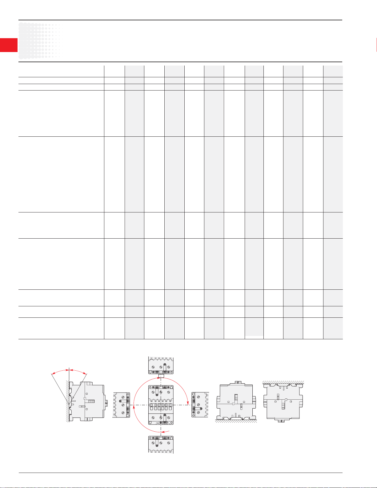
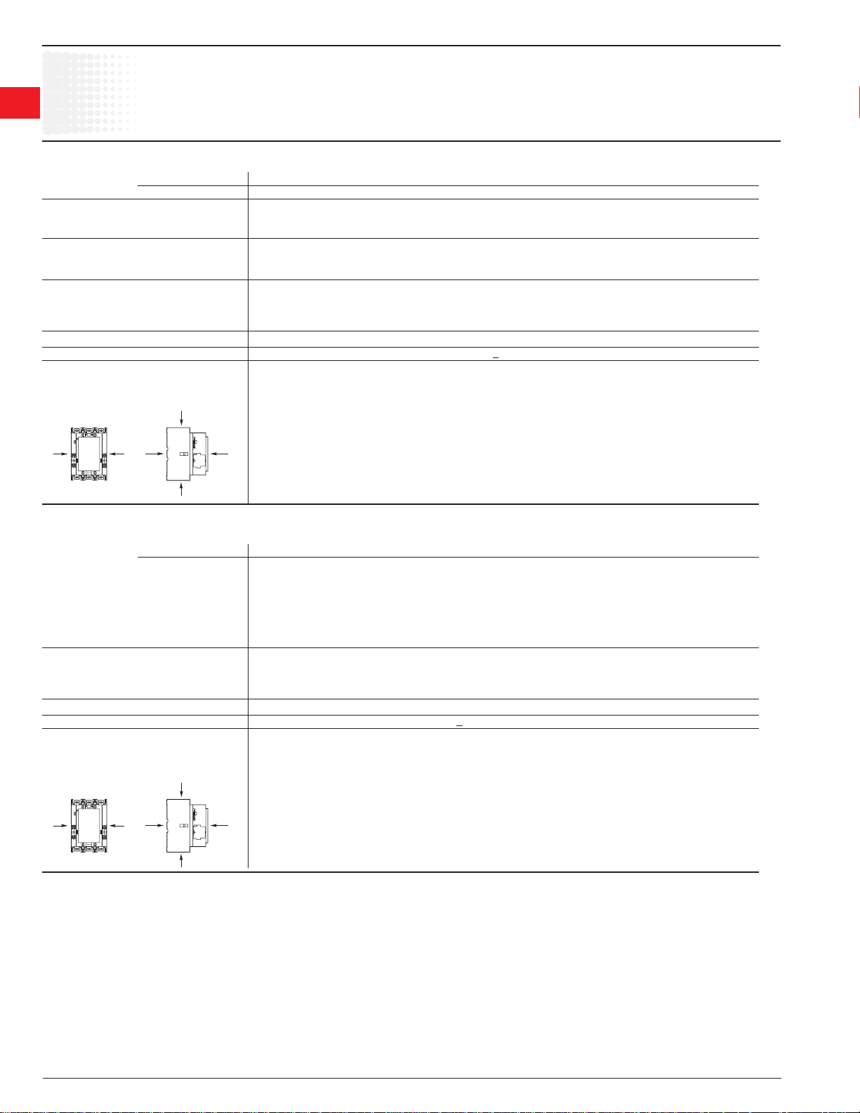
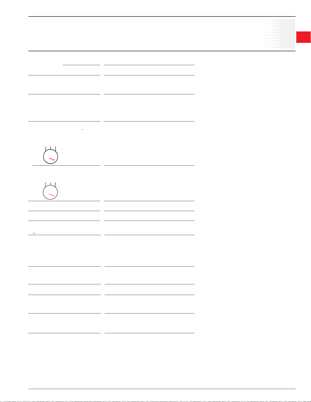
A/AE9 – A/AE/AF110, AL9 – AL40
AC & DC operated
Mounting positions
Pos. 2
ABB
30°
1 30A Ballast
1.36 Low Voltage Products & Systems
1SXU 000 023 C0201 ABB Inc. • 888-385-1221 • www.abb-control.com
30°
Pos. 1 ± 30°
ABB
ABB
ABB
Pos. 1
ABB
Pos. 3Pos. 4
Pos. 5
Pos. 6
(AL unauthorized)
Page 2
Across the line
UL & CSA Technical data
contactors
A/AF145 – AF750
AC & DC operated
ABB contactor frame size A/AF A/AF A/AF A/AF A/AF AF AF AF AF
145 185 210 260 300 400 460 580 750
NEMA size 4 — — 5 — — 6 — 7
Number of poles 3 3 3 3 3 3 3 3 3
AC rating information
NEMA maximum H.P. ratings 3 phase
200 VAC 40 — — 75 — — 150 — —
230 VAC 50 — — 100 — — 200 — 300
460/575 V 100 — — 200 — — 400 — 600
U.L. general purpose current 40°C 230 250 300 350 400 550 650 750 900
Max. 3 Ph switching motor loads Amps 130 156 192 248 302 414 480 590 720
U.L. maximum H.P. ratings 1 phase
115 VAC 10 15 — — — — — — —
230 VAC 25 30 40 50 — — — — —
U.L. maximum H.P. ratings 3 phase
200—208 VAC 40 50 60 75 100 125 150 200 250
220—240 VAC 50 60 75 100 100 150 200 250 300
440—480 VAC 100 125 150 200 250 350 400 500 600
550—600 VAC 125 150 200 250 300 400 500 600 700
Lighting – ballast and incandescent 600VAC 200 — 300 — 400 — — — —
CSA Elevator ratings
220 – 240VAC 3 phase 40 50 60 — — — —
240 – 480VAC 3 phase Consult Consult 75 100 125 — — — —
550 - 600VAC 3 phase factory factory 100 125 150 — — — —
230VAC 1 phase — — — — — — —
Auxiliary contacts
NEMA rating AC A600 A600 A600 A600 A600 A600 A600 A600 A600
AC rated voltage VAC 600 600 600 600 600 600 600 600 600
AC thermal rated current A 10 10 10 10 10 10 10 10 10
AC maximum volt—ampere making VA 7200 7200 7200 7200 7200 7200 7200 7200 7200
AC maximum volt—ampere breaking VA 720 720 720 720 720 720 720 720 720
NEMA rating DC P600 P600 P600 P600 P600 P600 P600 P600 P600
DC rated voltage VDC 600 600 600 600 600 600 600 600 600
DC thermal rated current A 5 5 5 5 5 5 5 5 5
DC Maximum make—break A 0.2 0.2 0.2 0.2 0.2 0.2 0.2 0.2 0.2
Approximate weight
Contactor lbs. 7.1 7.1 13 13 13 26 26 33 33
Starter lbs. 9.11 9.11 17.67 17.67 17.67 35 35 45 45
Terminal wire range
Number of wires per phase 1 1 1 1 2 2 2 2 3
Maximum short circuit ratings
MCCB,MCP,amps/kA 480VAC 400/85 400/85 800/85 800/85 800/85 800/80 800/80 1200/42 1200/42
MCCB,MCP,amps/kA 600VAC 400/35 400/35 800/35 800/35 800/35 800/42 800/42 — —
Fuse, amps—Type/kA 600VAC 400J/200 400J/200 600J/200 600J/200 600J/200 1000L/80 1000L/80 1200L/80 1200L/80
AWG 6-250MCM 6-250MCM 4-400MCM 4-400MCM 4-500MCM 250-500MCM 250-500MCM 2/0-500MCM 2/0-500MCM
1
1
Low Voltage Products & Systems 1.37
ABB Inc. • 888-385-1221 • www.abb-control.com 1SXU 000 023 C0201
Page 3
UL & CSA Technical data
1
Across the line
1
contactors
ABB contactor frame size AF AF
1350 1650
NEMA size — 8
Number of poles 3 3
AC rating information
NEMA maximum H.P. ratings 3 phase
200 VAC — —
230 VAC — 450
460/575 V — 900
U.L. general purpose current 40°C 1350 1650
Max. 3 Ph switching motor loads Amps 960 1080
U.L. maximum H.P. ratings 1 phase
115 VAC — —
230 VAC — —
U.L. maximum H.P. ratings 3 phase
200—208 VAC — —
220—240 VAC 400 450
440—480 VAC 800 900
550—600 VAC 900 1000
Auxiliary contacts
NEMA rating AC A600 A600
AC rated voltage VAC 600 600
AC thermal rated current A 10 10
AC maximum volt—ampere making VA 7200 7200
AC maximum volt—ampere breaking VA 720 720
NEMA rating DC P600 P600
DC rated voltage VDC 600 600
DC thermal rated current A 5 5
DC Maximum make—break A 0.2 0.2
Approximate weight
Contactor lbs. 75 75
Starter lbs. — —
Terminal wire range AWG 1/0-750 MCM 1/0-750 MCM
Number of wires per phase 4 6
Maximum short circuit ratings
MCCB,MCP,amps/kA 480VAC 2000/42 2000/42
MCCB,MCP,amps/kA 600VAC — —
Fuse, amps—Type/kA 600VAC 1600L/82 2000L/82
AF1350 – AF1650
AC & DC operated
1.38 Low Voltage Products & Systems
1SXU 000 023 C0201 ABB Inc. • 888-385-1221 • www.abb-control.com
Page 4
Across the line
C
UL/CSA & IEC Technical data
contactors
A/AE9 – A/AE/AF/TAE110
Contactor types: A..., AE... 9 12 16 26 30 40 45 50 63 75 95 110
AF..., TAE... – – – – – – 45 50 63 75 95 110
Rated insulation voltage U
according to IEC 60947-4-1 V 1000
according to UL/CSA V 600
Rated impulse withstand voltage U
Standards Devices complying with international standards IEC 60947-1 / 60947-4-1
and European standards EN 60947-1 / 60947-4-1
Air temperature close to contactor see "Conditions for use" page 1.50, for control voltage limits and authorized mounting positions
– fi tted with thermal O/L relay °C -25 to +55
– without thermal O/L relay °C -40 to +70 (55 max. for TAE... contactors)
– for storage °C -60 to +80 -40 to +70
Climatic withstand acc. to IEC 60068-2-30 and 60068-2-11 - UTE C 63-100 specifi cation II
30
Operating altitude m < 3000
Shock withstand
acc. IEC 60068-2-27 and EN 60068-2-27
Mounting position 1 (see page 1.50) 1/2 sinusoidal shock for 11 ms: no change in contact position
Shock direction Making position Breaking position
A 20 g 20 g
B1 10 g 5 g 1
B2 15 g 2 15 g 2
A
C1 20 g 20 g
C2 20 g 20 g
i
kV 8
imp.
acc. to IEC 68-2-
C1
B1
A
B2
2
mounting
Not valid for DIN-rail
1
1
1 3 g for AF 45-22, AE 45-22, AF 75-22 and AE 75-22.
2 10 g for AF 45-22, AE 45-22, AF 75-22 and AE 75-22.
Low Voltage Products & Systems 1.39
ABB Inc. • 888-385-1221 • www.abb-control.com 1SXU 000 023 C0201
Page 5
UL/CSA & IEC Technical data
1
Across the line
1
contactors
A/AF145 – AF750
Contactor types: A... 145 185 210 260 300 – – – –
AF... 145 185 210 260 300 400 460 580 750
Rated insulation voltage Ui
according to IEC 60947-4-1 V 1000
according to UL/CSA V600
Rated impulse withstand voltage U
Standards Devices complying with international standards IEC 60947-1 / 60947-4-1
and European standards EN 60947-1 / 60947-4-1
Air temperature close to contactor see "Conditions for use" page 1.51 , for control voltage limits and authorized mounting positions
– fi tted with thermal O/L relay °C -25 to +55
– without thermal O/L relay °C -40 to +70
– for storage °C -40 to +70
Climatic withstand acc. to IEC 60068-2-30
Operating altitude m < 3000
Shock withstand
acc. IEC 60068-2-27 and EN 60068-2-27
Mounting position 1 (
5 g in all directions (A, B1, B2, C1, C2)
see
imp.
page 1.51) 1/2 sinusoidal shock for 30 ms: no change in contact position
A/AF145 – AF1650
kV 8
C1
ABB
A
B1
A
B2
C2
AF1350 – AF1650
Contactor types: AF... 1350 1650
Rated insulation voltage Ui
according to IEC 60947-4-1 1000
according to UL/CSA V 600
Rated impulse withstand voltage U
Standards Devices complying with international standards IEC 60947-1 / 60947-4-1
and European standards EN 60947-1 / 60947-4-1
Air temperature close to contactor see "Conditions for use" page 1.51 , for control voltage limits and authorized mounting positions
– fi tted with thermal O/L relay °C-25 to +55
– without thermal O/L relay °C-40 to +70
– for storage °C-40 to +70
Climatic withstand acc. to IEC 60068-2-30
Operating altitude m < 3000
Shock withstand
acc. IEC 60068-2-27 and EN 60068-2-27
Mounting position 1 (See page 1.51) 1/2 sinusoidal shock for 30 ms: no change in contact position
5 g in all directions (A, B1, B2, C1, C2)
ABB
A
A
imp.
B1
kV 8
C1
B2
C2
1.40 Low Voltage Products & Systems
1SXU 000 023 C0201 ABB Inc. • 888-385-1221 • www.abb-control.com
Page 6
Across the line
IEC Technical data
contactors
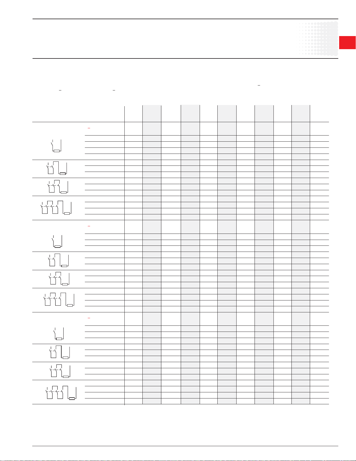
DC circuit switching
A/AE9 – GAE75
General
The arc switching on d.c. is more diffi cult than on a.c.
• For selecting a contactor it is essential to determine the current, the voltage and the L/R time constant of the controlled load.
• For information, typical time constant values are quoted hereafter: non inductive loads such as resistance furnaces (L/R ~ 1 ms), inductive loads such as shunt
motors (L/R ~ 2 ms) or series motors (L/R ~ 7.5 ms).
• The addition of a resistor in parallel with an inductive winding helps in the elimination of the arcs.
• All the poles required for breaking must be connected in series between the load and the source polarity not linked to earth (or chassis).
a.c. operated contactors A9 A12 A16 A26 A30 A40 A45 A50 A63 A75 GA75
a.c. / d.c. operated (electronic coil interface) – – – – – – AF45 AF50 AF63 AF75 –
d.c. operated contactors AE9 AE12 AE16 AE26 AE30 AE40 AE45 AE50 AE63 AE75 GAE75
Utilization category DC-1, L/R < 1 ms
≤ 72 V A 25 27 30 45 55 60 70 100 110 120 120
110 V A 10 15 20 – – – – – – – 120
220 V A – – – – – – – – – – 120
440 V A – – – – – – – – – – 100
600 V A – – – – – – – – – – 75
≤ 72 V A 25 27 30 45 55 60 70 100 110 120 –
110 V A 25 27 30 45 55 60 70 100 110 120 –
220 V A 10 15 20 – – – – – – – –
≤ 72 V A 25 27 30 45 55 60 70 100 110 120 –
110 V A 25 27 30 45 55 60 70 100 110 120 –
220 V A 25 27 30 45 55 60 70 100 110 120 –
≤ 72 V A 25 27 30 45 – – 70 100 – 120 –
110 V A 25 27 30 45 – – 70 100 – 120 –
220 V A 25 27 30 45 – – 70 100 – 120 –
440 V A 10 15 20 – – – – – – – –
Utilization category DC-3, L/R < 2 ms
≤ 72 V A 25 27 30 45 55 60 70 100 110 120 120
110 V A 6 7 8 – – – – – – – 120
220 V A – – – – – – – – – – 100
440 V A – – – – – – – – – – 85
≤ 72 V A 25 27 30 45 55 60 70 100 110 120 –
110 V A 25 27 30 45 55 60 70 100 110 120 –
220 V A 6 7 8 – – – – – – – –
≤ 72 V A 25 27 30 45 55 60 70 100 110 120 –
110 V A 25 27 30 45 55 60 70 100 110 120 –
220 V A 25 27 30 45 55 60 70 100 110 120 –
≤ 72 V A 25 27 30 45 – – 70 100 – 120 –
110 V A 25 27 30 45 – – 70 100 – 120 –
220 V A 25 27 30 45 – – 70 100 – 120 –
440 V A 6 7 8 – – – – – – – –
Utilization category DC-5, L/R < 7.5 ms
≤ 72 V A 9 12 16 25 30 40 50 50 63 75 85
110 V A 4 4 4 – – – – – – – 85
220 V A – – – – – – – – – – 85
440 V A – – – – – – – – – – 35
≤ 72 V A 25 27 30 45 55 60 70 100 110 120 –
110 V A 10 15 20 30 45 50 70 80 90 100 –
220 V A 4 4 4 – – – – – – – –
≤ 72 V A 25 27 30 45 55 60 70 100 110 120 –
110 V A 25 27 30 45 55 60 70 100 110 120 –
220 V A 9 12 16 25 30 40 50 50 63 75 –
≤ 72 V A 25 27 30 45 – – 70 100 – 120 –
110 V A 25 27 30 45 – – 70 100 – 120 –
220 V A 10 15 20 30 – – 70 70 – 100 –
440 V A 4 4 4 – – – – – – – –
1
1
Low Voltage Products & Systems 1.41
ABB Inc. • 888-385-1221 • www.abb-control.com 1SXU 000 023 C0201
Page 7
IEC Technical data
1
Across the line
1
contactors
Technical Data
• The tables indicate for the standard contactors the Ie max. operating currents depending on: the utilization category (i.e. L/R) DC-1, DC-3, DC-5 as defi ned in the
IEC 60947-4-1 publication, the operating voltage Ue and the pole coupling details. See page 1.81.
Ampere values quoted in the tables below are valid for a -25 … +70 °C temperature close to the contactors, as long as the AC-1 Ampere values (see pages 1.45
- 146) for the corresponding ambient temperature are not exceeded.
• Max. switching frequency: 300 ops/h.
• For switching higher d.c. ratings, we recommend the use of bar mounted contactors, R series (63 … 2000 A).
The selection table for AE 50 ... AE 110 contactors can be used for the TAE 50 ... TAE 110 types.
a.c. operated contactors A95 A110 A145 A185 A210 A260 A300 – – – –
a.c. / d.c. operated (electronic coil interface) AF95 AF110 AF145 AF185 AF210 AF260 AF300 AF400 AF460 AF580 AF750
d.c. operated contactors AE95 AE110 – – – – – – – – –
Utilization category DC-1, L/R < 1 ms
DC circuit switching
A/AF/AE95 – AF750
<110 V A 145 160 250 275 350 400 450 600 700 800 1050
220 V A – – – – – – – 600 700 800 1050
<110 V A 145 160 250 275 350 400 450 600 700 800 1050
220 V A 145 160 250 275 350 400 450 600 700 800 1050
440 V A – – – – – – – 600 700 800 1050
600 V A – – – – – – – 600 700 800 1050
Utilization category DC-3, L/R ≤ 2.5 ms
<110 V A 145 160 250 275 350 400 450 600 700 800 1050
220 V A – – – – – – – 600 700 800 1050
<110 V A 145 160 250 275 350 400 450 600 700 800 1050
220 V A 145 160 250 275 350 400 450 600 700 800 1050
440 V A – – – – – – – 600 700 800 1050
600 V A – – – – – – – 600 700 800 1050
Utilization category DC-5, L/R ≤ 15 ms
<110 V A 145 160 250 275 350 400 450 600 700 800 1050
220 V A – – – – – – – 600 700 800 1050
<110 V A 145 160 250 275 350 400 450 600 700 800 1050
220 V A 145 160 250 275 350 400 450 600 700 800 1050
440 V A – – – – – – – 600 700 800 1050
600 V A – – – – – – – 600 700 800 1050
<110 V A – – – – – – – 600 700 800 1050
<110 V A – – – – – – – 600 700 800 1050
<110 V A – – – – – – – 600 700 800 1050
1.42 Low Voltage Products & Systems
1SXU 000 023 C0201 ABB Inc. • 888-385-1221 • www.abb-control.com
Page 8
Across the line
IEC Technical data
contactors
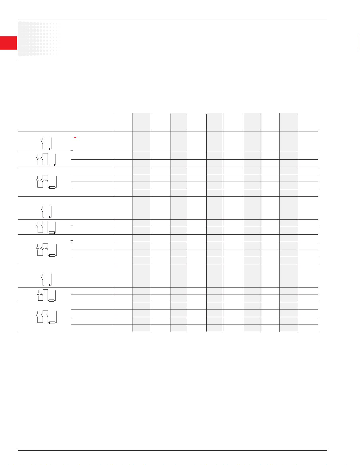
DC circuit switching
AL9 — AL40
General
The arc switching on d.c. is more diffi cult than on a.c.
• For selecting a contactor it is essential to determine the current, the voltage and the L/R time constant of the controlled load.
• For information, typical time constant values are quoted hereafter: non inductive loads such as resistance furnaces (L/R ~ 1 ms), inductive loads such as shunt
motors (L/R ~ 2 ms) or series motors (L/R ~ 7.5 ms).
• The addition of a resistor in parallel with an inductive winding helps in the elimination of the arcs.
• All the poles required for breaking must be connected in series between the load and the source polarity not linked to earth (or chassis).
A.C. operated contactors AL9 AL12 AL16 AL26 AL30 AL40
Utilization category DC-1, L/R < 1 ms
≤ 72 V A 25 27 30 45 55 60
110 V A 10 15 20 – – –
220 V A – – – – – –
440 V A – – – – – –
600 V A – – – – – –
≤ 72 V A 25 27 30 45 55 60
110 V A 25 27 30 45 55 60
220 V A 10 15 20 – – –
≤ 72 V A 25 27 30 45 55 60
110 V A 25 27 30 45 55 60
220 V A 25 27 30 45 55 60
≤ 72 V A 25 27 30 45 – –
110 V A 25 27 30 45 – –
220 V A 25 27 30 45 – –
440 V A 10 15 20 – – –
Utilization category DC-3, L/R < 2 ms
≤ 72 V A 25 27 30 45 55 60
110 V A 6 7 8 – – –
220 V A – – – – – –
440 V A – – – – – –
≤ 72 V A 25 27 30 45 55 60
110 V A 25 27 30 45 55 60
220 V A 6 7 8 – – –
≤ 72 V A 25 27 30 45 55 60
110 V A 25 27 30 45 55 60
220 V A 25 27 30 45 55 60
≤ 72 V A 25 27 30 45 – –
110 V A 25 27 30 45 – –
220 V A 25 27 30 45 – –
440 V A 6 7 8 – – –
Utilization category DC-5, L/R < 7.5 ms
≤ 72 V A 9 12 16 25 30 40
110 V A 4 4 4 – – –
220 V A – – – – – –
440 V A – – – – – –
≤ 72 V A 25 27 30 45 55 60
110 V A 10 15 20 30 45 50
220 V A 4 4 4 – – –
≤ 72 V A 25 27 30 45 55 60
110 V A 25 27 30 45 55 60
220 V A 9 12 16 25 30 40
≤ 72 V A 25 27 30 45 – –
110 V A 25 27 30 45 – –
220 V A 10 15 20 30 – –
440 V A 4 4 4 – – –
1
1
Low Voltage Products & Systems 1.43
ABB Inc. • 888-385-1221 • www.abb-control.com 1SXU 000 023 C0201
Page 9
IEC Technical data
1
Across the line
1
contactors
General
The arc switching on d.c. is more diffi cult than on a.c.
• For selecting a contactor it is essential to determine the current, the voltage and the L/R time constant of the controlled load.
• For information, typical time constant values are quoted hereafter: non inductive loads such as resistance furnaces (L/R ~ 1 ms), inductive loads such as shunt
motors (L/R ~ 2 ms) or series motors (L/R ~ 7.5 ms).
• The addition of a resistor in parallel with an inductive winding helps in the elimination of the arcs.
• All the poles required for breaking must be connected in series between the load and the source polarity not linked to earth (or chassis).
Technical Data
• The tables indicate for the standard contactors the Ie max. operating currents depending on: the utilization category (i.e. L/R) DC-1, DC-3, DC-5 as defi ned in the
IEC 60947-4-1 publication (see page 1.75 for more details), the operating voltage Ue and the pole coupling details.
Ampere values quoted in the tables below are valid for a -25 … +70 °C temperature close to the contactors, as long as the AC-1 Ampere values (see page 1.61)
for the corresponding ambient temperature are not exceeded.
• Max. switching frequency: 300 ops/h.
• For switching higher d.c. ratings, we recommend the use of bar mounted contactors, R series (63 … 2000 A).
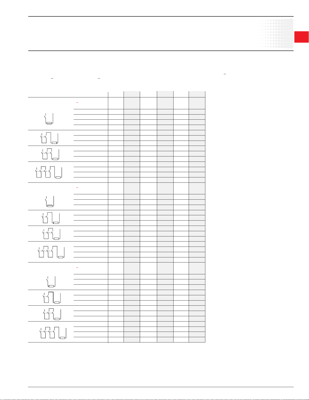
Selection Table
a.c. / d.c. operated contactors EK110 EK150 EK175 EK210 EK370 EK550 EK1000
Utilization category DC-1, L/R < 1 ms
≤ 72 V A 120 145 210 210 370 550 –
110 V A 120 145 210 210 370 550 –
≤ 72 V A 200 200 300 300 550 800 –
110 V A 200 200 300 300 550 800 –
220 V A 200 200 300 300 550 800 –
≤ 72 V A 200 200 300 300 550 800 –
110 V A 200 200 300 300 550 800 –
220 V A 200 200 300 300 550 800 –
440 V A – – 210 210 450 650 –
600 V A – – – – 450 650 –
≤ 72 V A 200 200 300 300 550 800 –
110 V A 200 200 300 300 550 800 –
220 V A 200 200 300 300 550 800 –
440 V A 200 200 260 300 450 650 –
600 V A – – 260 300 450 650 –
Utilization category DC-3, L/R < 2 ms
DC circuit switching
EK110 — EK1000
≤ 72 V A 120 145 210 210 370 550 –
≤ 72 V A 135 145 210 210 450 650 –
110 V A 135 135 210 210 450 650 –
220 V A 135 135 210 210 450 650 –
≤ 72 V A 135 145 210 210 450 650 –
110 V A 135 135 210 210 450 650 –
220 V A 135 135 210 210 450 650 –
440 V A – – 210 210 450 650 –
600 V A – – – – 450 650 –
≤ 72 V A 135 145 210 210 450 650 –
110 V A 135 135 210 210 450 650 –
220 V A 135 135 210 210 450 650 –
440 V A 135 135 210 210 450 650 –
600 V A – – 170 210 450 650 –
Utilization category DC-5, L/R < 7.5 ms
≤ 72 V A 135 145 210 210 450 650 –
110 V A 135 135 210 210 450 650 –
220 V A 135 135 210 210 450 650 –
≤ 72 V A 135 145 210 210 450 650 –
110 V A 135 135 210 210 450 650 –
220 V A 135 135 210 210 450 650 –
440 V A – – 210 210 450 650 –
600 V A – – – – 450 650 –
≤ 72 V A 135 145 210 210 450 650 –
110 V A 135 135 210 210 450 650 –
220 V A 135 135 210 210 450 650 –
440 V A 135 135 210 210 450 650 –
600 V A – – 170 210 450 650 –
1.44 Low Voltage Products & Systems
1SXU 000 023 C0201 ABB Inc. • 888-385-1221 • www.abb-control.com
Page 10
Across the line
IEC Technical data
contactors
A/AE9 — A/AE/AF/TAE110
1
Main Pole - Utilization Characteristics
Contactor types: A..., AE... 9 12 16 26 30 40 45 50 63 75 95 110
AF..., TAE... – – – – – – 45 50 63 75 95 110
Rated operational voltage Ue max. V 690 1000 (690 for AF... contactors)
Rated frequency limits Hz 25-400
Conventional free-air thermal current Ith
acc. to IEC 60947-4-1,
open contactors ø ≤ 40 °C A 26 28 30 45 65 65 100 100 125 125 145 160
with conductor cross-sectional area mm2 4 4 4 6 16 16 35 35 50 50 50 70
Rated operational current I
for air temperature close to contactor
ø ≤ 40 °C A 25 27 30 45 55 60 70 100 115 125 145 160
Ue max. 690 V ø ≤ 55 °C A 22 25 27 40 55 60 60 85 95 105 135 145
ø ≤ 70 °C 3 A 18 20 23 32 39 42 50 70 80 85 115 130
with conductor cross-sectional area mm2 2.5 4 4 6 10 16 25 35 50 50 50 70
Utilization categorie AC-3
for air temperature close to contactor < 55 °C
Rated operational current Ie AC-3 1
220-230-240 V A 9 12 17 26 33 40 40 53 65 75 96 110
3-phase motors 380-400 V A 9 12 17 26 32 37 37 50 65 75 96 110
415 V A 9 12 17 26 32 37 37 50 65 72 96 110
440 V A 9 12 16 26 32 37 37 45 65 70 93 100
500 V A 9 12 14 22 28 33 33 45 55 65 80 100
690 V A 7 9 10 17 21 25 25 35 43 46 65 82
1000 V A – – – – – – – 23 2 25 2 28 2 30 2 30 2
Rated operational power AC-3 1
1500 r.p.m. 50 Hz
1800 r.p.m. 60 Hz
3-phase motors 415 V kW 4 5.5 9 11 15 18.5 18.5 25 37 40 55 59
440 V kW 4 5.5 9 15 18.5 22 22 25 37 40 55 59
500 V kW 5.5 7.5 9 15 18.5 22 22 30 37 45 55 59
690 V kW 5.5 7.5 9 15 18.5 22 22 30 37 40 55 75
1000 V kW – – – – – – – 30 2 33 2 37 2 40 2 40 2
Rated making capacity AC-3
according to IEC 60947-4-1 10 x I
Rated breaking capacity AC-3
according to IEC 60947-4-1 8 x I
Short-circuit protection for contactors
without thermal O/L relay - Motor protection excluded
Ue < 500 V a.c. - gG type fuse A 25 32 32 50 63 80 100 125 160 160 200
Rated short-time withstand current I
at 40 °C ambient temp., in free air,
from a cold state 1 s A 250 280 300 400 600 1000 1320 1320
10 s A 100 120 140 210 400 650 800 800
30 s A 60 70 80 110 225 370 500 500
1 min A 50 55 60 90 150 250 350 350
15 min A 26 28 30 45 65 110 110 135 135 160 175
Maximum breaking capacity
cos ø = 0.45 (cos ø = 0.35 for I
at 440 V A 250 420 820 900 1300 1160
at 690 V A 90 170 340 490 630 800
Heat dissipation per pole
I
Max. electrical switching frequency
– for AC-1 cycles/h 600 600 (300 for AF..., AE... TAE...) 300
– for AC-3 cycles/h 1200 (600 for AE...) 600 (300 for AF..., AE... TAE...) 300
– for AC-2, AC-4 cycles/h 300 150 150
Electrical durability see pages 1.70 - 1.73
Mechanical durability
– millions of operating cycles 10 (5 for AE... and TAE... contactors)
– max. mechanical switching
frequency cycles/h 3600 (300 for AF... contactors)
M
M
3
3
220-230-240 V kW 2.2 3 4 6.5 9 11 11 15 18.5 22 25 30
380-400 V kW 4 5.5 7.5 11 15 18.5 18.5 22 30 37 45 55
M
3
/ AC-1
e
{
AC-3
e
AC-3
e
cw
> 100 A)
e
Ie / AC-1 W 0.8 1 1.2 1.8 2.5 3 2.5 5 6.5 7 6.5 7.5
/ AC-3 W 0.1 0.2 0.35 0.6 0.9 1.3 0.65 1.3 1.5 2 2.7 3.6
e
1
1 For the corresponding hp/A values of 1500 r.p.m., 50Hz, 3-phase motors, see page 1.76.
2 AF... contactors excluded
3 Unauthorized for TAE... contactors.
Low Voltage Products & Systems 1.45
ABB Inc. • 888-385-1221 • www.abb-control.com 1SXU 000 023 C0201
Page 11
IEC Technical data
1
Across the line
1
contactors
Main Pole - Utilization Characteristics
Contactor types: A... 145 185 210 260 300 – – – –
AF... 145 185 210 260 300 400 460 580 750
Rated operational voltage Ue max. V 690
Rated frequency limits Hz 25 ... 400
Conventional free-air thermal current Ith
acc. to IEC 60947-4-1,
open contactors ø ≤ 40 °C A 250 275 350 400 500 600 700 800 1050
with conductor cross-sectional area 1 mm2 120 150 185 240 300
Rated operational current Ie / AC-1
for air temperature close to contactor
ø ≤ 40 °C A 250 275 350 400 500 600 700 800 1050
Ue max. 690 V ø ≤ 55 °C A 230 250 300 350 400 500 600 700 800
ø ≤ 70 °C A 180 180 240 290 325 400 480 580 720
with conductor cross-sectional area mm2 120 150 185 240 300
Utilization categorie AC-3
for air temperature close to contactor < 55 °C
Rated operational current Ie AC-3
220-230-240 V A 145 185 210 260 305 400 460 580 750
3-phase motors 380-400 V A 145 185 210 260 305 400 460 580 750
415 V A 145 185 210 260 300 400 460 580 750
440 V A 145 185 210 240 280 400 460 580 750
500 V A 145 170 210 240 280 400 460 580 750
690 V A 120 170 210 220 280 350 400 500 650
1000 V A – – – – – – – – –
Rated operational power AC-3
1500 r.p.m. 50 Hz
1800 r.p.m. 60 Hz
3-phase motors 415 V kW 75 90 110 140 160 220 250 355 425
440 V kW 75 90 110 140 160 220 250 355 450
500 V kW 90 110 132 180 200 250 315 400 520
690 V kW 110 132 160 200 250 315 355 500 600
1000 V kW – – – – – – – – –
Rated making capacity AC-3
according to IEC 60947-4-1 10 x I
Rated breaking capacity AC-3
according to IEC 60947-4-1 8 x I
Short-circuit protection for contactors
without thermal O/L relay - Motor protection excluded
Ue < 500 V a.c. - gG type fuse A 315 355 400 500 630 800 1000
Rated short-time withstand current I
at 40 °C ambient temp., in free air,
from a cold state 1 s A 1800 2000 2500 3500 4600 7000
10 s A 1200 1500 1700 2400 4400 6400
30 s A 800 1000 1200 1500 3100 4500
1 min A 600 800 1000 1100 2500 3500
15 min A 280 320 400 500 840 1300
Maximum breaking capacity
cos ø = 0.45 (cos ø = 0.35 for I
at 440 V A 1500 2000 2300 2600 3000 4000 5000 6000 7500
at 690 V A 1200 1600 2000 2400 2500 3500 4500 5000 7000
Heat dissipation per pole
I
Max. electrical switching frequency
– for AC-1 cycles/h 300 300 300 300
– for AC-3 cycles/h 300 300 300 300
– for AC-2, AC-4 cycles/h 150 150 60 60
Electrical durability see pages 1.65 ... 1.69 – – – –
Mechanical durability
– millions of operating cycles 5 3
– max. mechanical switching
frequency cycles/h 3600 (300 for AF... contactors) 300
M
3
M
3
{
220-230-240 V kW 45 55 59 80 90 110 132 160 220
380-400 V kW 75 90 110 140 160 200 250 315 400
e
Ie / AC-1 W 13 16 18 25 32 30 42 32 50
e
A/AF145 – AF750
3
2 x 185 2 x 240 2 x 240
3
2 x 185 2 x 240 2 x 240
AC-3
e
AC-3
e
cw
> 100 A)
/ AC-3 W 5 8 9 14 18 16 21 17 28
2 x 80 x 5 2
2 x 80 x 5 2
1 Conductors with preparation.
2 Dimensions of the bars (in mm).
3 For currents above 450A, use terminal extension / enlargement pieces LX 300 / LW 300 see page 1.31).
1.46 Low Voltage Products & Systems
1SXU 000 023 C0201 ABB Inc. • 888-385-1221 • www.abb-control.com
Page 12
IEC Technical data
AF1350 – AF1650
Main Pole - Utilization Characteristics
Contactor types: AF... 1350 1650
Rated operational voltage U
Rated frequency limits Hz 25-400 25-400
Conventional free-air thermal current Ith
acc. to IEC 60947-4-1,
open contactors ø ≤ 40 °C A 1350 1650
with conductor cross-sectional area1
Rated operational current I
for air temperature close to contactor
ø ≤ 40 °C A 1350 1650
Ue max. 690 V ø ≤ 55 °C A 1150 1450
ø ≤ 70 °C A 1000 1270
with conductor cross-sectional area mm2
Utilization categorie AC-3
for air temperature close to contactor < 55 °C
Rated operational current Ie AC-3
220-230-240 V A 860 1050
3-phase motors 380-400 V A 860 1050
415 V A 860 1050
440 V A 860 1050
500 V A — —
690 V A — —
1000 V A — —
Rated operational power AC-3
1500 r.p.m. 50 Hz
1800 r.p.m. 60 Hz
3-phase motors 415 V kW 500 600
440 V kW 560 670
500 V kW — —
690 V kW — —
1000 V kW — —
Rated making capacity AC-3
according to IEC 60947-4-1
Rated breaking capacity AC-3
according to IEC 60947-4-1
Short-circuit protection for contactors
without thermal O/L relay - Motor protection excluded
Ue < 500 V a.c. - gG type fuse A
Rated short-time withstand current I
at 40 °C ambient temp., in free air,
from a cold state 1 s A 10,000 12,000
10 s A 8000 10,000
30 s A 6000 7500
1 min A 4500 5500
15 min A 1600 2200
Maximum breaking capacity
cos ø = 0.45 (cos ø = 0.35 for I
at 440 V A 10,000 12,000
at 690 V A — —
Max. electrical switching frequency
– for AC-1 cycles/h 60 60
– for AC-3 cycles/h
– for AC-2, AC-4 cycles/h
Electrical durability 50,000 50,000
Mechanical durability
– millions of operating cycles 500,000 500,000
– max. mechanical switching
frequency cycles/h 60 60
M
3
220-230-240 V kW 257 315
380-400 V kW 475 560
M
3
max. V 1000 1000
e
mm2 2/100x5 3/100x5
/ AC-1
e
{
cw
> 100 A)
e
2 x 80 x 51
Product coordination
with ABB circuit breaker
2 x 80 x 51
10 x I
, AC-3
e
8 x I
, AC-3
e
Consult factory
Across the line
contactors
1
1
1 Dimensions of the bars (in mm).
Low Voltage Products & Systems 1.47
ABB Inc. • 888-385-1221 • www.abb-control.com 1SXU 000 023 C0201
Page 13
IEC Technical data
1
Across the line
1
contactors
Magnet System Characteristics for A... Contactors
Contactor types: A... 9 12 16 26 30 40 45 50 63 75 95 110
Rated control circuit voltage U
– at 50 Hz V 20 ... 690
– at 60 Hz V 24 ... 600
Coil operating limits ø < 55 °C ø < 70 °C
according to IEC 60947-4-1 0.85 ... 1.1 x U
Drop-out voltage in % of Uc roughly 40 ... 65 %
Coil consumption
Average pull-in value 50 Hz VA 70 120 180 350
60 Hz VA 80 140 210 450
50/60 Hz 1 VA/VA 74/70 125/120 190/180 410/365
Average holding value 50 Hz VA/W 8/2 12/3 18/5.5 22/6.5
60 Hz VA/W 8/2 12/3 18/5.5 26/8
50/60 Hz 1
Operating time
between coil energization and:
– N.O. contact closing ms 10 ... 26 8 ... 21 8 ... 27 10 ... 25
– N.C. contact opening ms 7 ... 21 6 ... 18 7 ... 22 7 ... 22
between coil de-energization and:
– N.O. contact opening ms 4 ... 11 4 ... 11 4 ... 11 7 ... 15
– N.C. contact closing ms 9 ... 16 7 ... 14 7 ... 14 10 ... 18
c
Magnet System Characteristics for AF... Contactors
Contactor types: AF... – – – – – – 45 50 63 75 95 110
Rated control circuit voltage Uc
– at 50 Hz V 48 ... 250 48 ... 250
– at 60 Hz V 48 ... 250 48 ... 250
– d.c. V 20 ... 250 20 ... 250
Coil operating limits ø < 70 °C
according to IEC 60947-4-1 0.85 ... 1.1 x U
Drop-out voltage in % of U
Coil consumption
Average pull-in value 50 Hz VA 210 350
60 Hz VA 210 350
d.c. W 190 400
Average holding value 50 Hz VA/W 7/2.8 7/3.5
60 Hz VA/W 7/2.8 7/3.5
d.c. W 2.8 2
Operating time
between coil energization and:
– N.O. contact closing ms 30 ... 100 30 ... 80
– N.C. contact opening ms 27 ... 95 27 ... 77
between coil de-energization and:
– N.O. contact opening ms 30 ... 110 55 ... 125
– N.C. contact closing ms 35 ... 115 60 ... 130
55 %
c
A/AF9 — AF110
0.85 ... 1.1 x U
c
VA/W 8/2 12/3 18/5.5 27/7.5
c
c
1 50/60 Hz coils: voltage codes 8 0 to 8 8.
1.48 Low Voltage Products & Systems
1SXU 000 023 C0201 ABB Inc. • 888-385-1221 • www.abb-control.com
page 1.28.
see
Page 14
Across the line
IEC Technical data
contactors
A145 — AF750
Magnet System Characteristics for A... Contactors
Contactor types: A... 145 185 210 260 300 – – – –
Rated control circuit voltage Uc
– at 50 Hz V 24 ... 690
– at 60 Hz V 24 ... 690
Coil operating limits ø < 70 °C
according to IEC 60947-4-1 0.85 ... 1.1 x U
Drop-out voltage in % of U
Coil consumption
Average pull-in value 50 Hz VA 550 1350
60 Hz VA 600 1550
50/60 Hz 1 VA/VA 700/650 1700/1550
Average holding value 50 Hz VA/W 35/11 60/16
60 Hz VA/W 40/12 65/19
50/60 Hz 1 VA/W 44/13 80/21
Operating time
between coil energization and:
– N.O. contact closing ms 13 ... 27 17 ... 35
– N.C. contact opening ms 8 ... 22 12 ... 30
between coil de-energization and
– N.O. contact opening ms 5 ... 10 7 ... 13
– N.C. contact closing ms 9 ... 13 10 ... 16
roughly 25 ... 65 %
c
c
1
1
Magnet System Characteristics for AF... Contactors
Contactor types: AF... 145 185 210 260 300 400 460 580 750
Rated control circuit voltage U
– at 50 Hz V 48 ... 250
– at 60 Hz V 48 ... 250
– d.c. V 24 ... 250
Coil operating limits ø < 70 °C
according to IEC 60947-4-1 0.85 ... 1.1 x U
Drop-out voltage in % of U
Coil consumption
Average pull-in value 50 Hz VA 430 470 890 850
60 Hz VA 430 470 890 850
d.c. W 500 520 990 950
Average holding value 50 Hz VA/W 12/3.5 10/2.5 12/4 12/4.5
60 Hz VA/W 12/3.5 10/2.5 12/4 12/4.5
d.c. W 2 2 4 4.5
Operating time
between coil energization and:
– N.O. contact closing ms 30 ... 115 50 ... 120
– N.C. contact opening ms 30 ... 115 50 ... 120
between coil de-energization and
– N.O. contact opening ms 25 ... 80 40 ... 70
– N.C. contact closing ms 25 ... 80 40 ... 70
c
55 %
c
c
1 50/60 Hz coils: voltage codes 8 0 to 8 8. see page 1.28.
Low Voltage Products & Systems 1.49
ABB Inc. • 888-385-1221 • www.abb-control.com 1SXU 000 023 C0201
Page 15
IEC Technical data
1
Across the line
1
contactors
Magnet System Characteristics for AF... Contactors
Contactor types: AF... 1350 1650
Rated control circuit voltage U
– at 50 Hz V 100 - 250
– at 60 Hz V 100 - 250
– d.c. V 100 - 250
Coil operating limits ø < 70 °C
according to IEC 60947-4-1 0.85 ... 1.1 x U
Drop-out voltage in % of U
Coil consumption
Average pull-in value 50 Hz VA 1900
60 Hz VA 1900
d.c. W 1700
Average holding value 50 Hz VA/W 48/17
60 Hz VA/W 48/17
d.c. W 16
Operating time
between coil energization and:
– N.O. contact closing ms 50 - 80
– N.C. contact opening ms 50 - 80
between coil de-energization and
– N.O. contact opening ms 35 - 55
– N.C. contact closing ms 35 - 55
With PLC
between coil energization and
– N.O. contact opening ms 40 - 65
– N.C. contact closing ms 40 - 65
between coil de-energization and
– N.O. contact opening ms 10 - 30
– N.C. contact closing ms 10 - 30
c
55 %
c
AF1350 — AF1650
c
1 50/60 Hz coils: voltage codes 8 0 to 8 8. see page 1.28.
1.50 Low Voltage Products & Systems
1SXU 000 023 C0201 ABB Inc. • 888-385-1221 • www.abb-control.com
Page 16
Across the line
IEC Technical data
contactors
AE9 — AE110
TAE45 — TAE110
Magnet System Characteristics for AE... Contactors
Contactor types: AE... 9 12 16 26 30 40 45 50 63 75 95 110
Rated control circuit voltage U
V d.c. 12 ... 250
Coil operating limits ø < 55 °C ø < 70 °C
according to IEC 60947-4-1 0.85 ... 1.1 x U
Drop-out voltage in % of U
Coil consumption - Average values
– pull-in value W 90 110 200 400
– holding value W 2 2.5 4 2.4
Coil time constant
– open L/R ms 2 3 3 6
– closed L/R ms 9 16 15 30 ... 40
Operating time
between coil energization and:
– N.O. contact closing ms 10 ... 16 13 ... 21 13 ... 30 15 ... 25
– N.C. contact opening ms 8 ... 12 11 ... 16 10 ... 27 12 ... 22
between coil de-energization and
– N.O. contact opening ms 5 ... 14 1 6 ... 12 1 5 ... 15 1 15 ... 20 1
– N.C. contact closing ms 11 ... 17 1 8 ... 16 1 8 ... 18 1 18 ... 23 1
Magnet System Characteristics for TAE... Contactors
Contactor types: TAE... – – – – – – 45 50 – 75 95 110
Rated control circuit voltage U
V d.c. 17 ... 264
Coil operating limits ø < 55 °C
according to IEC 60947-4-1 U
Drop-out voltage in % of U
Coil consumption
values for U
– pull-in value W 120 ... 250 300 ... 1000
– holding value W 1.7 ... 6.5 2 ... 7
Coil time constant
– open L/R ms 3 6
– closed L/R ms 15 40
Operating time
between coil energization and:
– N.O. contact closing ms 13 ... 30 15 ... 25
– N.C. contact opening ms 10 ... 27 12 ... 22
between coil de-energization and
– N.O. contact opening ms 5 ... 15 2 15 ... 20 2
– N.C. contact closing ms 8 ... 18 2 18 ... 23 2
min. ... Uc max.
c
c
c
c
max. roughly 20 ... 35 %
c
roughly 10 ... 30 % roughly 15 ... 40 %
c
min. ... Uc max.
c
1
1
1 The use of surge suppressors increases the opening time on a scale of 1.1 to 1.5 for a varistor suppressor and on a scale of 4 to 8 for a diode suppressor.
AE 9 ... AE 40 contactors and U
2 The use of surge suppressors increases the opening time on a scale of 1.1 to 1.5 for a varistor suppressor and on a scale of 4 to 8 for a diode suppressor.
Low Voltage Products & Systems 1.51
ABB Inc. • 888-385-1221 • www.abb-control.com 1SXU 000 023 C0201
> 110 V: table values for contactors with RV 5 surge suppressor (factory mounted).
c
Page 17
IEC Technical data
1
Across the line
1
contactors
Built-in Auxiliary Contacts - Utilization Characteristics
Contactor types: A... 9 12 16 26 30 40 45 50 63 75 95 110
Rated operational voltage Ue
Conventional free air thermal
current I
Rated frequency limits Hz 25 ... 400 – – – – – –
Rated operational current I
according to IEC 60947-5-1
24-127 V 50/60 Hz A 6 – – – – – –
220-240 V 50/60 Hz A 4 – – – – – –
380-440 V 50/60 Hz A 3 – – – – – –
500 V 50/60 Hz A 2 – – – – – –
690 V 50/60 Hz A 2 – – – – – –
Rated operational current I
according to IEC 60947-5-1
24 V d.c. A / W 6 / 144 – – – – – –
48 V d.c. A / W 2.8 / 134 – – – – – –
72 V d.c. A / W 2 / 144 – – – – – –
125 V d.c. A / W 1.1 / 138 – – – – – –
250 V d.c. A / W 0.55 / 138 – – – – – –
Rated making capacity
acc. to IEC 60947-5-1 10 x I
Rated breaking capacity
acc. to IEC 60947-5-1 10 x I
Short-circuit protection
gG type fuse A 10 – – – – – –
Rated short-time withstand current I
for 1.0 s A 100 – – – – – –
for 0.1 s A 140 – – – – – –
Minimum switching capacity V / mA 17 / 5 – – – – – –
Non-overlapping time between
N.O. and N.C. contacts ms > 2 – – – – – –
Insulating resistance at 500 V d.c.
after durability test MOhm 5 – – – – – –
Heat dissipation per pole at 6 A W 0.10 – – – – – –
- ø ≤ 40 °C A 16 – – – – – –
th
max.
/ AC-15
e
/ DC-13
e
A9 — A110
V 690 – – – – – –
/ AC-15 – – – – – –
e
/ AC-15 – – – – – –
e
cw
1.52 Low Voltage Products & Systems
1SXU 000 023 C0201 ABB Inc. • 888-385-1221 • www.abb-control.com
Page 18
Across the line
IEC Technical data
contactors
A/AE9 — AF/TAE110
1
Mounting characteristics
Contactor types: A..., AE... 9 12 16 26 30 40 45 50 63 75 95 110
AF..., TAE... – – – – – – 45 50 63 75 95 110
Mounting positions see "Conditions for use"
Mounting distances The contactors can be assembled side by side
Mounting
on DIN rail 35 x 7.5 mm 35 x 15 mm
according to IEC 715 and EN 50022 / EN 50023
by screws (not supplied) 2 x M4 2 x M6
Conditions for Use
Sustainable utilization conditions for contactors involving at the same time the Mounting position, Ambient temperature and Control voltage operating limits are
summarized in the table below.
Contactors Mounting position Ambient temperature Control voltage
A 9 ... A 110, AE 9 ... AE 110
> 55 °C unauthorized –
AF 45 ... AF 110
6 unauthorized – –
TAE 45 ... TAE 110 > 55 °C unauthorized –
6 unauthorized – –
Notes for 4-pole contactors
Whatever the coil voltage: Pos. 5 unauthorized for A 45-22-00, AE 45-22-00, A 75-22-00, AE 75-22-00 contactors.
For 60 Hz coil voltage: (only for devices fi tted with CA 5-.. and CAL 5-11 auxiliary contacts or TP timer)
– A 45-40-00, A 50-40-00 and A 75-40-00 contactors
Mounting positions 1 to 5 and ambient temperature < 55 °C: tolerance reduced to 0.9 ... 1.1 U
– A 45-22-00 and A 75-22-00 contactors
Mounting positions 1 to 4 (pos. 5 unauthorized) and ambient temperature < 55 °C: tolerance reduced to 0.9 ... 1.1 Uc (instead of 0.85 ... 1.1 Uc) for coil voltage
codes 7 and 8 .
For mounting position 6 or ambient temperature of 55 to 70 °C the information given on this page remains applicable.
55 ... 70 °C U
1, 1 + 30°, 2, 3, 4, 5 < 70 °C 0.85 U
35 x 15 mm 75 x 25 mm 75 x 25 mm
1, 1 + 30°, 2, 3, 4, 5
< 55 °C 0.95 ... 1.1 x U
6
1, 1 + 30°, 2, 3, 4, 5
< 55 °C 0.85 ... 1.1 x U
c
< 55 °C U
(instead of 0.85 ... 1.1 Uc) for coil voltage codes 7 and 8 .
c
min. ... Uc max.
c
c
c
min. ... 1.1 x Uc max.
c
1
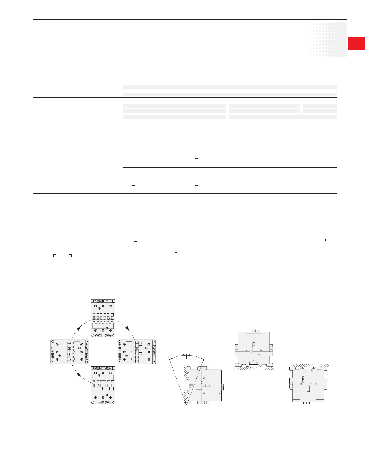
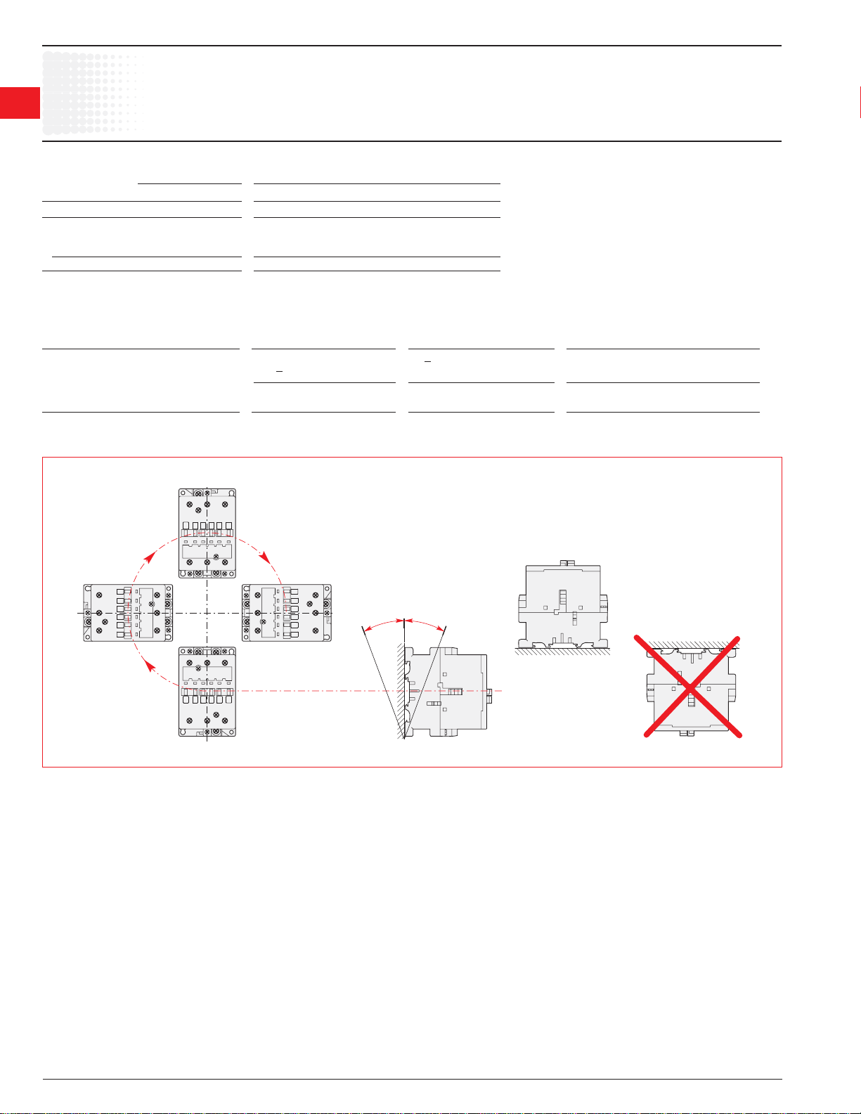
Mounting Positions (see the above table for authorized positions)
Position
2
ABB
Position 4
ABB
ABB
Position 1
ABB
-30°
Position 3
Position 1 ± 30°
+30°
Position 5
Position 6
Low Voltage Products & Systems 1.53
ABB Inc. • 888-385-1221 • www.abb-control.com 1SXU 000 023 C0201
Page 19
IEC Technical data
1
Across the line
1
contactors
Mounting Characteristics — A/AF145 — AF750
Contactor types: A... 145 185 210 260 300 – – – –
AF... 145 185 210 260 300 400 460 580 750
Mounting positions see "Condition for use"
Mounting distances The contactors can be assembled side by side
Fixing
on DIN rail – – – – – – – – –
according to IEC 715 and EN 50022 / EN 50023
by screws (not supplied) 4 x M5 4 x M6
Mounting Characteristics — AF1350 — AF1650
Contactor types: AF 1350 1650
Mounting positions see "Condition for use"
Mounting distances The contactors can be assembled side by side
Fixing
on DIN rail – –
according to IEC 715 and EN 50022 / EN 50023
by screws (not supplied) 4 x M8
Conditions for Use
Sustainable utilization conditions for contactors involving at the same time the Mounting position, Ambient temperature and Control voltage operating limits are
summarized in the table below.
Contactors Mounting position Ambient temperature Control voltage
A 145 ... A 300
6 unauthorized – –
AF 145 ... AF 750
6 unauthorized – –
1, 1 + 30°, 2, 3, 4, 5 < 70 °C 0.85 ... 1.1 x U
1, 1 + 30°, 2, 3, 4, 5 < 70 °C 0.85 x U
A/AF145 — AF1650
c
min. ... 1.1 x Uc max.
c
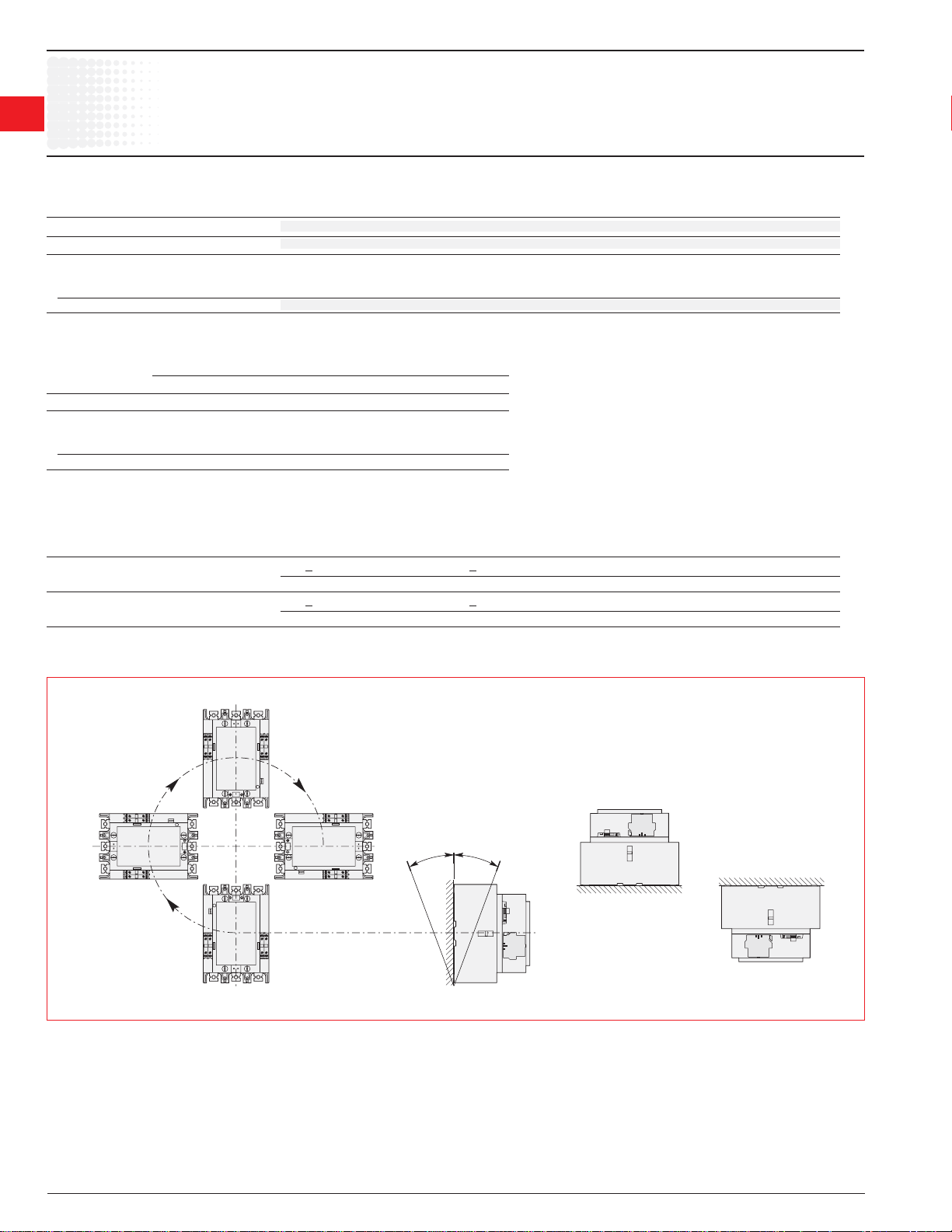
Mounting Positions (see the above table for authorized positions)
Position 2
ABB
Position 4
ABB
ABB
Position 3
ABB
Position 1
-30°
+30°
Position 5
Position 6
Position 1 ± 30°
1.54 Low Voltage Products & Systems
1SXU 000 023 C0201 ABB Inc. • 888-385-1221 • www.abb-control.com
Page 20

Across the line
IEC Technical data
contactors
A/AE9 — AF/TAE110
Connecting Characteristics
Contactor types: A..., AE... 9 12 16 26 30 40 45 50 63 75 95 110
AF..., TAE... – – – – – – 45 50 63 75 95 110
Main terminals
1
1
with cable clamp with double with single connector with single
connector
Connecting capacity (min. ... max.)
Main conductors (poles)
Rigid: solid (≤ 4 mm
stranded (≥ 6 mm2) 2 x mm2 1 ... 4 1.5 ... 6 2.5 ... 16 6 ... 16 6 ... 35
Rigid with connector
single for Cu cable mm
single for Al/Cu cable mm2 – – – – – – – – – – – –
double for Al/Cu cable mm2 – – – – – – – – – – – –
Flexible with cable end 1 x mm
2 x mm2 0.75 ... 2.5 0.75 ... 4 2.5 ... 10 6 ... 25 6 ... 35
Bars or lugs L mm ≤ 8 10 – – – – – – 30 2
l mm > 3.7 4.2 – – – – – – 6
Auxiliary conductors
(built-in auxiliary terminals + coil terminals)
Rigid solid 1 x mm
2 x mm2 1 ... 4 0.75 ... 2.5
Flexible with cable end 1 x mm
2 x mm2 0.75 ... 2.5
Lugs L mm ≤ 8 1 8
l mm > 3.7 1 3.7
Degree of protection acc. to IEC 60947-1 / Protection against direct contact acc. to VDE 0106 - Part. 100
EN 60947-1 and IEC 60529 / EN 60529
– Main terminals IP 20 IP 10
– Coil terminals IP 20
– Built-in auxiliary terminals IP 20 – – – – – –
Screw terminals (delivered in open position, screws of unused terminals must be tightened)
Main terminals (+,-) pozidriv 2 screws hexagon socket
M3.5 M4 M5 M6 M8 (s = 4 mm)
Coil terminals M3.5 (+,-) pozidriv 2 screws with cable clamp
Built-in auxiliary terminals (+,-) pozidriv 2 screws with cable clamp – – – – – –
M3.5 M4 M5 – – – – – –
Tightening torque
Main pole terminals
– recommended Nm / lb.in 1.00 / 9 1.7 / 15 2.30 / 20 4.00 / 35 6.00 / 53
– max. Nm 1.20 2.20 2.60 4.50 6.50
Coil terminals
– recommended Nm / lb.in 1.00 / 9
– max. Nm 1.20
Built-in auxiliary terminals
– recommended Nm / lb.in 1.00 / 9 1.7 / 15 1.00 / 9 – – – – – –
– max. Nm 1.20 2.20 1.20 – – – – – –
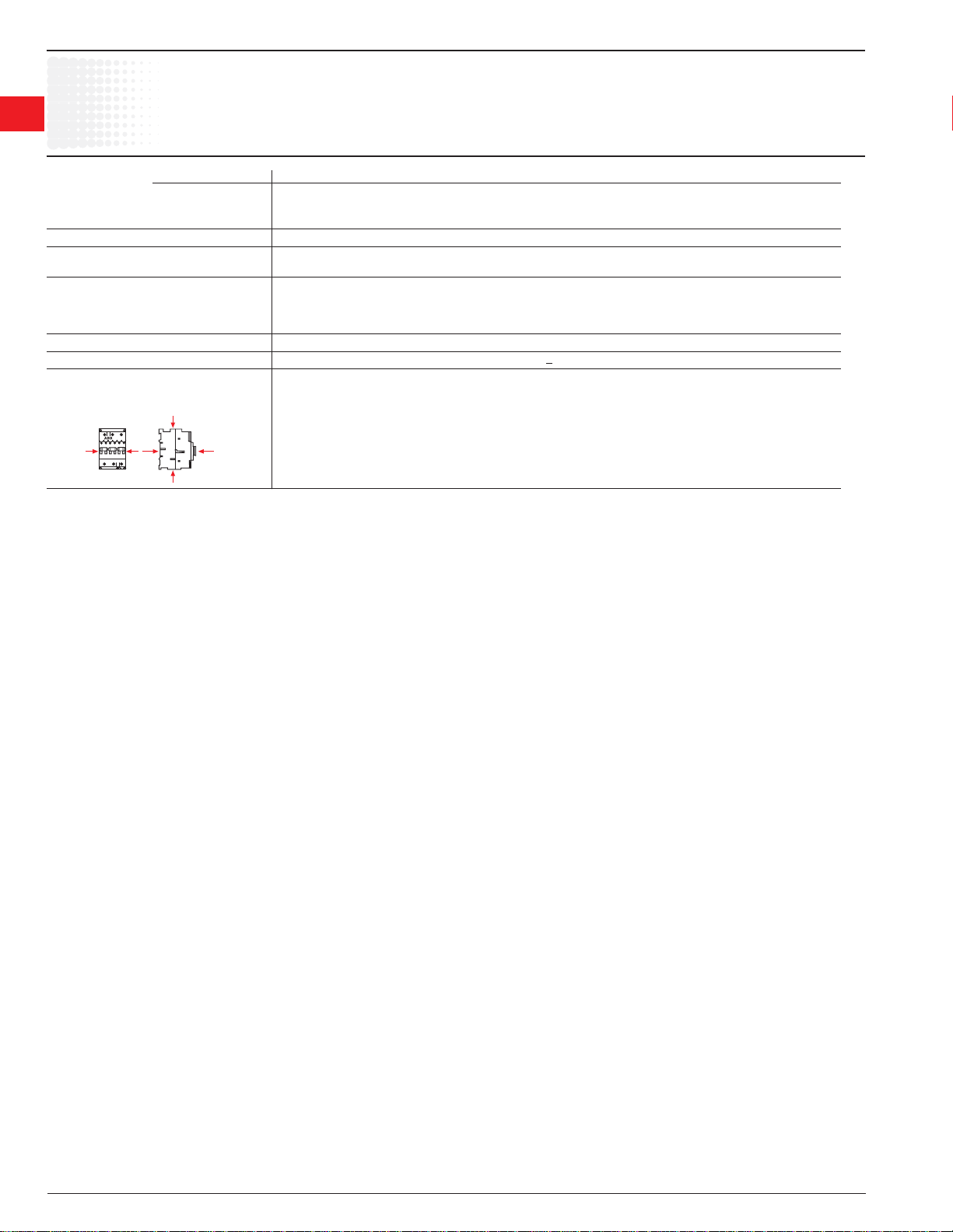
Terminal marking and positioning see pages 1.34
2
) 1 x mm2 1 ... 4 1.5 ... 6 2.5 ... 16 6 ... 50 10 ... 95
}
2
– – – – – – – – – – – –
2
0.75 ... 2.5 0.75 ... 4 2.5 ... 10 6 ... 35 10 ... 70
L
l
2
1 ... 4 0.75 ... 2.5
2
0.75 ... 2.5 1 ... 2.5 0.75 ... 2.5
L
l
2 x (5.6 x 6.5 mm) (14 x 14 mm)
(13 x 10 mm) connector
1 L < 8 and l > 3.7 for coil terminal - L < 10 and l > 4.2 for built-in auxiliary terminals.
2 With LW 110 enlargement piece. See page 1.31.
Low Voltage Products & Systems 1.55
ABB Inc. • 888-385-1221 • www.abb-control.com 1SXU 000 023 C0201
Page 21

IEC Technical data
1
Across the line
1
contactors
Connecting Characteristics
Contactor types: A... 145 185 210 260 300 – – – –
AF... 145 185 210 260 300 400 460 580 750
Main terminals
Flat type
A/AF145 — AF750
17.5
5
20
5
25
6
22.5
6
40
22.5
ø8.5
Connecting capacity (min. ... max.)
Main conductors (poles)
Rigid: 1 x mm
Rigid with connector
single for Cu cable mm2 6 ... 185 16 ... 240 240 300
single for Al/Cu cable mm2 25 ... 150 120 ... 240 240 300
double for Al/Cu cable mm2 – 2 x 95 ... 120 2 x 240 3 x 185
Flexible
1 x mm2 – – – – – – – – –
2 x mm2 – – – – – – – – –
Bars or lugs L mm ≤ 24 32 47 / 45 52 / 50
Ø mm > 8 10 10 12
Auxiliary conductors
(coil terminals)
Rigid solid 1 x mm
2 x mm2 1 ... 4
Flexible with cable end
Lugs L mm ≤ 8
l mm > 3.7
Degree of protection acc. to IEC 60947-1 / Protection against direct contact acc. to VDE 0106 - part 100
EN 60947-1 and IEC 60529 / EN 60529
– Main terminals IP 00
– Coil terminals IP 20
– Built-in auxiliary terminals –
Screw terminals
Main terminals Screws and bolts
M8 M10 M10 M12
Coil terminals (delivered in open position) M3.5 (+,-) pozidriv 2 screws with cable clamp
Built-in auxiliary terminals – – – – – – – – –
– – – – – – – – –
Tightening torque
Main pole terminals
– recommended
– max.
Coil terminals
– recommended
– max.
Built-in auxiliary terminals
– recommended
– max.
Terminal marking and positioning see pages 1.36 & 1.37
ø
1 x mm2 0.75 ... 2.5
L
l
2
2 x mm2 – – – – – – – – –
L
2 x mm2 0.75 ... 2.5
Nm / lb.in 18 / 160 28 / 240 40 / 354 45 / 443
Nm / lb.in 1.00 / 9
Nm / lb.in – – – – – – – – –
– – – – – – – – –
2
1 ... 4
Nm 20 30 44 49
Nm 1.20
Nm – – – – – – – – –
ø 10.2
ø6.5
ø10.5
ø 6.5
ø 12.5
1.56 Low Voltage Products & Systems
1SXU 000 023 C0201 ABB Inc. • 888-385-1221 • www.abb-control.com
Page 22

IEC Technical data
AF1350 — AF1650
Connecting Characteristics
Contactor types: AF... 1350 1650
Main terminals
Flat type
Connecting capacity (min. ... max.)
Main conductors (poles)
Rigid: 1 x mm
Rigid with connector
single for Cu cable mm
single for Al/Cu cable mm
double for Al/Cu cable mm2
Flexible
1 x mm2
2 x mm2
Bars or lugs L mm ≤ 100 100
Ø mm > 12 12
Auxiliary conductors
(coil terminals)
Rigid solid 1 x mm
2 x mm2 1...4 1...4
Flexible with cable end
Lugs L mm ≤ 8 8
l mm > 3.7 3.7
Degree of protection acc. to IEC 60947-1 /
EN 60947-1 and IEC 60529 / EN 60529
– Main terminals IP 00 IP 00
– Coil terminals IP 20 IP 20
– Built-in auxiliary terminals
Screw terminals Screw and bolts
Main terminals M12
Coil terminals (delivered in open position) M3.5 (+,-) pozidriv 2 screws with cable clamp
Built-in auxiliary terminals — —
Tightening torque
Main pole terminals
– recommended
– max.
Coil terminals
– recommended
– max.
Built-in auxiliary terminals
– recommended
– max.
ø
1 x mm2 0.75...2.5 0.75...2.5
L
l
2 —
2 — —
2 x mm
2 — —
2 — —
— —
— —
— —
L
2
1...4 1...4
2 x mm2 0.75...2.5 0.75...2.5
Nm / lb.in
Nm / lb.in
Nm / lb.in — —
45/443 45/443
Nm
49 49
1.00 / 9
Nm
1.20 1.20
Nm
— —
—
1.00 / 9
Across the line
contactors
1
1
Low Voltage Products & Systems 1.57
ABB Inc. • 888-385-1221 • www.abb-control.com 1SXU 000 023 C0201
Page 23
C
UL/CSA & IEC Technical data
1
Across the line
1
contactors
Contactor types: AL AL9 AL12 AL16 AL26 AL30 AL40
Rated insulation voltage Ui
according to IEC 60947-4-1 V 1000
according to UL/CSA V 600
Rated impulse withstand voltage U
Standards Devices complying with international standards IEC 60947-1 / 60947-4-1
and European standards EN 60947-1 / 60947-4-1
Air temperature close to contactor see "Conditions for use" page 1.50, for control voltage limits and authorized mounting positions
– fi tted with thermal O/L relay °C -25 to +55
– without thermal O/L relay °C -40 to +70 (55 max. for TAE... contactors)
– for storage °C -60 to +80
Climatic withstand acc. to IEC 60068-2-30 and 60068-2-11 - UTE C 63-100 specifi cation II
Operating altitude m < 3000
Shock withstand
acc. IEC 60068-2-27 and EN 60068-2-27
Mounting position 1 (see page 1.50) 1/2 sinusoidal shock for 11 ms: no change in contact position
Shock direction Making position Breaking position
A 20 g 20 g
B1 10 g 5 g
A
B2 15 g 15 g
C1 20 g 20 g
C2 20 g 20 g
B1
A
imp.
C1
2
AL9 — AL40
kV 8
B2
1.58 Low Voltage Products & Systems
1SXU 000 023 C0201 ABB Inc. • 888-385-1221 • www.abb-control.com
Page 24
IEC Technical data
AL9 — AL40
Main Pole - Utilization Characteristics
Contactor types: AL AL9 AL12 AL16 AL26 AL30 AL40
Rated operational voltage Ue max. V 690
Rated frequency limits Hz 25-400
Conventional free-air thermal current Ith
acc. to IEC 60947-4-1,
open contactors ø ≤ 40 °C A 26 28 30 45 65 65
with conductor cross-sectional area mm2 4 4 4 6 16 16 35
Rated operational current I
for air temperature close to contactor
ø ≤ 40 °C A 25 27 30 45 55 60
Ue max. 690 V ø ≤ 55 °C A 22 25 27 40 55 60
ø ≤ 70 °C 3 A 18 20 23 32 39 42
with conductor cross-sectional area mm2 2.5 4 4 6 10 16
Utilization categorie AC-3
for air temperature close to contactor < 55 °C
Rated operational current Ie AC-3 1
220-230-240 V A 9 12 17 26 33 40
3-phase motors 380-400 V A 9 12 17 26 32 37
415 V A 9 12 17 26 32 37
440 V A 9 12 16 26 32 37
500 V A 9 12 14 22 28 33
690 V A 7 9 10 17 21 25
1000 V A – – – – – –
Rated operational power AC-3 1
1500 r.p.m. 50 Hz
1800 r.p.m. 60 Hz
3-phase motors 415 V kW 4 5.5 9 11 15 18.5
440 V kW 4 5.5 9 15 18.5 22
500 V kW 5.5 7.5 9 15 18.5 22
690 V kW 5.5 7.5 9 15 18.5 22
1000 V kW – – – – – –
Rated making capacity AC-3
according to IEC 60947-4-1 10 x I
Rated breaking capacity AC-3
according to IEC 60947-4-1 8 x I
Short-circuit protection for contactors
without thermal O/L relay - Motor protection excluded
Ue < 500 V a.c. - gG type fuse A 25 32 32 50 63
Rated short-time withstand current I
at 40 °C ambient temp., in free air,
from a cold state 1 s A 250 280 300 400 600
10 s A 100 120 140 210 400
30 s A 60 70 80 110 225
1 min A 50 55 60 90 150
15 min A 26 28 30 45 65
Maximum breaking capacity
cos ø = 0.45 (cos ø = 0.35 for I
at 440 V A 250 — — 420 820
at 690 V A 90 — — 170 340
Heat dissipation per pole
I
Max. electrical switching frequency
– for AC-1 cycles/h 600
– for AC-3 cycles/h 1200
– for AC-2, AC-4 cycles/h 300
Mechanical durability
– millions of operating cycles 10
– max. mechanical switching
frequency cycles/h 3600
M
M
3
3
220-230-240 V kW 2.2 3 4 6.5 9 11
380-400 V kW 4 5.5 7.5 11 15 18.5
M
3
/ AC-1
e
{
AC-3
e
AC-3
e
cw
> 100 A)
e
Ie / AC-1 W 0.8 1 1.2 1.8 2.5
/ AC-3 W 0.1 0.2 0.35 0.6 0.9
e
Across the line
contactors
1
1
Low Voltage Products & Systems 1.59
ABB Inc. • 888-385-1221 • www.abb-control.com 1SXU 000 023 C0201
Page 25
IEC Technical data
1
Across the line
1
contactors
Magnet system characteristics for AL contactors
Contactor types: AL AL9 AL12 16 26 30 40
Rated control circuit voltage U
V d.c. 12 ... 240 (24V & 48V for AL...Z)
Coil operating limits ø < 55 °C
according to IEC 60947-4-1 0.85 ... 1.1 x U
Drop-out voltage in % of U
Coil consumption - Average values
– pull-in value W 3 (2.4 for AL9Z - AL16Z) 3.5
– holding value W 3 (2.4 for AL9Z - AL16Z) 3.5
Coil time constant
– open L/R ms 40
– closed L/R ms 90
Operating time
between coil energization and:
– N.O. contact closing ms 50 ... 75
– N.C. contact opening ms 45 ... 70
between coil de-energization and
– N.O. contact opening ms 15 ... 30
– N.C. contact closing ms 17 ... 32
c
roughly 15 ... 30 %
c
Magnet System Characteristics for TAL... Contactors
Contactor types: TAL TAL9 TAL12 TAL16 TAL26 TAL30 TAL40
Rated control circuit voltage U
V d.c. 9 ... 264
Coil operating limits ø < 55 °C
according to IEC 60947-4-1 0.85 ... 1.1 x U
Drop-out voltage in % of U
Coil consumption
values for U
– Uc max. DC W 8.5 9
– Uc min. DC W 2.5 2.7
– Uc DC W 5 5.4
Operating time
between coil energization and:
– N.O. contact closing ms 50 ... 100 55 ... 110
– N.C. contact opening ms 20 ... 70 25 ... 75
between coil de-energization and
– N.O. contact opening ms 10 ... 17 1 12 ... 18 1
– N.C. contact closing ms 16 ... 27 1 18 ... 28 1
max. and 20 °C
c
c
max. roughly 20... 35 %
c
AL9 — AL40, TAL9 – TAL40
c
c
1 The use of surge suppressors increases the opening time on a scale of 1.1 to 1.5 for a varistor suppressor and on a scale of 4 to 8 for a diode suppressor.
1.60 Low Voltage Products & Systems
1SXU 000 023 C0201 ABB Inc. • 888-385-1221 • www.abb-control.com
Page 26
IEC Technical data
AL9 — AL40
Built-in Auxiliary Contacts - Utilization Characteristics
Contactor types: AL AL9 AL12 AL16 AL26 AL30 AL40
Rated operational voltage Ue
Conventional free air thermal
current I
- ø ≤ 40 °C A 16
th
Rated frequency limits Hz 25 ... 400
Rated operational current I
according to IEC 60947-5-1
24-127 V 50/60 Hz A 6
220-240 V 50/60 Hz A 4
380-440 V 50/60 Hz A 3
500 V 50/60 Hz A 2
690 V 50/60 Hz A 2
Rated operational current I
according to IEC 60947-5-1
24 V d.c. A / W 6 / 144
48 V d.c. A / W 2.8 / 134
72 V d.c. A / W 2 / 144
125 V d.c. A / W 1.1 / 138
250 V d.c. A / W 0.55 / 138
Rated making capacity
acc. to IEC 60947-5-1 10 x I
Rated breaking capacity
acc. to IEC 60947-5-1 10 x I
Short-circuit protection
gG type fuse A 10
Rated short-time withstand current I
for 1.0 s A 100
for 0.1 s A 140
Minimum switching capacity V / mA 17 / 5
Non-overlapping time between
N.O. and N.C. contacts ms > 2
Insulating resistance at 500 V d.c.
after durability test MOhm 5
Heat dissipation per pole at 6 A W 0.10
max.
V 690
/ AC-15
e
/ DC-13
e
cw
/ AC-15
e
/ AC-15
e
Across the line
contactors
1
1
Low Voltage Products & Systems 1.61
ABB Inc. • 888-385-1221 • www.abb-control.com 1SXU 000 023 C0201
Page 27
IEC Technical data
1
Across the line
1
contactors
Mounting characteristics
Contactor types: AL AL9 AL12 AL16 AL26 AL30 AL40
Mounting positions see "Conditions for use"
Mounting distances The contactors can be assembled side by side
Mounting
on DIN rail 35 x 7.5 mm
according to IEC 715 and EN 50022 / EN 50023
by screws (not supplied) 2 x M4
Conditions for Use
Sustainable utilization conditions for contactors involving at the same time the Mounting position, Ambient temperature and Control voltage operating limits are
summarized in the table below.
Contactors Mounting position Ambient temperature Control voltage
AL9 – AL40
55 ... 70 °C U
Mounting Positions (see the above table for authorized positions)
AL9 — AL40
Position
2
35 x 15 mm
1, 1 + 30°, 2, 3, 4, 5
6 (Unauthorized)
< 55 °C 0.85 ... 1.1 x U
c
c
Position 4
ABB
ABB
Position 1
ABB
ABB
Position 3
-30°
+30°
Position 1 ± 30°
Position 5
Position 6
1.62 Low Voltage Products & Systems
1SXU 000 023 C0201 ABB Inc. • 888-385-1221 • www.abb-control.com
Page 28

Across the line
IEC Technical data
contactors
AL9 — AL40
Connecting Characteristics
Contactor types: AL AL9 AL12 AL16 AL26 AL30 AL40
Main terminals
with cable clamp with double
connector
Connecting capacity (min. ... max.)
Main conductors (poles)
Rigid: solid (≤ 4 mm
stranded (≥ 6 mm2) 2 x mm2 1 ... 4 1.5 ... 6 2.5 ... 16
Rigid with connector
single for Cu cable mm
single for Al/Cu cable mm2 – – – – – –
double for Al/Cu cable mm2 – – – – – –
Flexible with cable end 1 x mm
2 x mm2 0.75 ... 2.5 0.75 ... 4 2.5 ... 10
Bars or lugs L mm ≤ 8 10 – –
l mm > 3.7 4.2 – –
Auxiliary conductors
(built-in auxiliary terminals + coil terminals)
Rigid solid 1 x mm
2 x mm2 1 ... 4
Flexible with cable end 1 x mm
2 x mm2 0.75 ... 2.5
Lugs L mm ≤ 8 1 8
l mm > 3.7 1 3.7
Degree of protection acc. to IEC 60947-1 / Protection against direct contact acc. to VDE 0106 - Part. 100
EN 60947-1 and IEC 60529 / EN 60529
– Main terminals IP 20
– Coil terminals IP 20
– Built-in auxiliary terminals IP 20
Screw terminals (delivered in open position, screws of unused terminals must be tightened)
Main terminals (+,-) pozidriv 2 screws
M3.5 M4 M5
Coil terminals M3.5 (+,-) pozidriv 2 screws with cable clamp
Built-in auxiliary terminals (+,-) pozidriv 2 screws with cable clamp
M3.5 M4 M5
Tightening torque
Main pole terminals
– recommended Nm / lb.in 1.00 / 9 1.7 / 15 2.30 / 20
– max. Nm 1.20 2.20 2.60
Coil terminals
– recommended Nm / lb.in 1.00 / 9
– max. Nm 1.20
Built-in auxiliary terminals
– recommended Nm / lb.in 1.00 / 9 1.7 / 15 1.00 / 9
– max. Nm 1.20 2.20 1.20
Terminal marking and positioning see pages 1.35
2
) 1 x mm2 1 ... 4 1.5 ... 6 2.5 ... 16
}
2
– – – – – –
2
0.75 ... 2.5 0.75 ... 4 2.5 ... 10
L
l
2
1 ... 4
2
0.75 ... 2.5
L
l
2 x (5.6 x 6.5 mm)
1
1
1 L < 8 and l > 3.7 for coil terminal - L < 10 and l > 4.2 for built-in auxiliary terminals.
2 With LW 110 enlargement piece. See page 1.31.
Low Voltage Products & Systems 1.63
ABB Inc. • 888-385-1221 • www.abb-control.com 1SXU 000 023 C0201
Page 29
IEC Technical data
1
Across the line
1
contactors
General Technical Data
Contactor types: EK... 110 150 175 210 370 550 1000
Rated insulation voltage Ui
according to IEC 60947-4-1
according to UL/CSA
Rated impulse withstand voltage U
Standards Devices complying with international standards IEC 60947-1 / 60947-4-1
and European standards EN 60947-1 / 60947-4-1
Air temperature close to contactor see "Conditions for use" page 1.63, for control voltage limits and authorized mounting positions
– fi tted with thermal O/L relay °C -25 to +55
– without thermal O/L relay °C -40 to +70
– for storage °C -50 to +70
Climatic withstand acc. to IEC 60068-2-30
Operating altitude m < 3000
Shock withstand
acc. IEC 60068-2-27 and EN 60068-2-27
Mounting position 1 (see page 1.63) 1/2 sinusoidal shock for 15 ms: no change in contact position
Contactor in making or breaking position
Shock direction: A, C1, C2: 10 g
B1: 10 g
ABB
A AB1
B2: 10 g
V 1000
V 600
imp.
EK110 — EK1000
kV 8
C1
B2
C2
1.64 Low Voltage Products & Systems
1SXU 000 023 C0201 ABB Inc. • 888-385-1221 • www.abb-control.com
Page 30
Across the line
IEC Technical data
contactors
EK110 — EK1000
Main Pole - Utilization Characteristics
Contactor types: EK... 110 150 175 210 370 550 1000
Rated operational voltage Ue max. V 1000 690
Rated frequency limits Hz 25 ... 400
Conventional free-air thermal current Ith
acc. to IEC 60947-4-1,
open contactors ø ≤ 40 °C A 200 250 300 350 550 800 1000
with conductor cross-sectional area mm2 95 150 185 240 2 x 185 2 x 240 2 x 300
Rated operational current I
for air temperature close to contactor
ø ≤ 40 °C A 200 250 300 350 550 800 1000
Ue max. 690 V ø ≤ 55 °C A 180 230 270 310 470 650 800
ø ≤ 70 °C A 155 200 215 250 400 575 720
with conductor cross-sectional area mm2 95 150 185 240 2 x 185 2 x 240 2 x 300
Utilization categorie AC-3
for air temperature close to contactor < 55 °C
Rated operational current Ie AC-3
220-230-240 V A 120 145 210 400 550 –
3-phase motors 380-400 V A 120 145 210 400 550 –
415 V A 120 145 210 400 550 –
440 V A 120 145 210 370 550 –
500 V A 120 145 210 370 550 –
690 V A 120 120 210 370 550 –
1000 V A 64 80 113 155 175 –
Rated operational power AC-3
1500 r.p.m. 50 Hz 220-230-240 V kW 30 45 59 110 160 –
1800 r.p.m. 60 Hz 380-400 V kW 55 75 110 200 280 –
3-phase motors 415 V kW 55 75 110 220 315 –
440 V kW 59 75 110 220 315 –
500 V kW 75 90 132 250 400 –
690 V kW 110 110 160 355 500 –
1000 V kW 90 110 160 220 250 –
Rated making capacity AC-3
according to IEC 60947-4-1 10 x I
Rated breaking capacity AC-3
according to IEC 60947-4-1 8 x I
Short-circuit protection for contactors
without thermal O/L relay - Motor protection excluded
Ue < 500 V a.c. - gG type fuse A 250 355 630 800 1000
Rated short-time withstand current I
at 40 °C ambient temp., in free air,
from a cold state 1 s A 1700 1800 2300 5500 6800
10 s A 900 1200 1680 5300 6400
30 s A 600 700 1000 3700 4400
1 min A 450 550 800 3000 3400
15 min A 210 250 320 1000 1200
Maximum breaking capacity
cos ø = 0.45 (cos ø = 0.35 for I
at 440 V A 1400 1500 2000 5000 5400 –
at 690 V A 1100 1200 1700 5000 5400 –
Heat dissipation per pole
I
Max. electrical switching frequency
– for AC-1 cycles/h 300 300
– for AC-3 cycles/h 300 –
– for AC-2, AC-4 cycles/h 150 120 –
Electrical durability see pages 1.75
Mechanical durability
– millions of operating cycles 10 5
– max. mechanical switching
frequency cycles/h 3600 3600
M
3
M
3
/ AC-1
e
{
AC-3 –
e
AC-3 –
e
cw
> 100 A)
e
Ie / AC-1 W 10 13 18 40 60 80
/ AC-3 W 3 5 9 15 25 –
e
1
1
Low Voltage Products & Systems 1.65
ABB Inc. • 888-385-1221 • www.abb-control.com 1SXU 000 023 C0201
Page 31
IEC Technical data
1
Across the line
1
contactors
Magnet System Characteristics for EK... Contactors - a.c. Operated
Contactor types: EK... 110 150 175 210 370 550 1000
Rated control circuit voltage U
– at 50 Hz V 24 ... 500 48 ... 500
– at 60 Hz V 24 ... 600 110 ... 600
Coil operating limits ø < 70 °C
according to IEC 60947-4-1 0.85 ... 1.1 x U
Drop-out voltage in % of Uc roughly 45 ... 65 %
Coil consumption
Average pull-in value 50 Hz1 VA 800 1100 3500
60 Hz1 VA 900 1200 4000
50/60 Hz2
Average holding value 50 Hz1 VA/W 44/15 52/18 125/50
60 Hz1 VA/W 52/18 65/22 140/60
50/60 Hz2
Operating time
between coil energization and:
– N.O. contact closing ms 20 ... 401 / 30 ... 502 30 ... 60
– N.C. contact opening ms 15 ... 351 / 25 ... 452 25 ... 55
between coil de-energization and:
– N.O. contact opening ms 7.5 ... 151 / 95 ... 1202 10 ... 20
– N.C. contact closing ms 10 ... 181 / 100 ... 1252 13 ... 23
c
Magnet System Characteristics for EK... Contactors - d.c. Operated
Contactor types: EK... 110 150 175 210 370 550 1000
Rated control circuit voltage U
V d.c. 12 ... 220 24 ... 220
Coil operating limits ø < 70 °C
according to IEC 60947-4-1 0.85 ... 1.1 x U
Drop-out voltage in % of U
Coil consumption - Average values
– pull-in value W 500 630 1100
– holding value W 2.5 2.5 20
Coil time constant
– open L/R ms 8 12
– closed L/R ms 50 60
Operating time
between coil energization and:
– N.O. contact closing ms 30 ... 50 60 ... 80
– N.C. contact opening ms 27 ... 47 55 ... 75
between coil de-energization and:
– N.O. contact opening ms 10 ... 35
– N.C. contact closing ms 13 ... 38
c
c
EK110 — EK1000
c
VA/VA 500/500 630/630 3800/3400
VA/W 2.5/2.5 2.5/2.5 140/60
roughly 15 ... 50 %
c
1 "A" coil voltage codes see page 1.29.
2 50/60 Hz "E" coil voltage codes see page 1.29.
1.66 Low Voltage Products & Systems
1SXU 000 023 C0201 ABB Inc. • 888-385-1221 • www.abb-control.com
Page 32

Across the line
IEC Technical data
contactors
EK110 — EK1000
1
Mounting Characteristics
Contactor types: EK... 110 150 175 210 370 550 1000
Mounting positions see "Conditions for use"
Fixing
by screws (supplied) 4 x M6 4 x M6 (1)
Conditions for Use
Sustainable utilization conditions for contactors involving at the same time the Mounting position, Ambient temperature and Control voltage operating limits are
summarized in the table below.
Contactors Mounting position Ambient temperature Control voltage
E110 ... EK210 1, 1 + 30°, 3, 4, 5 < 70 °C 0.85 ... 1.1 x U
E370 ... EK1000 1, 1 + 30°, 2, 3, 4, 5 < 70 °C 0.85 ... 1.1 x U
6 unauthorized
2, 6 unauthorized
Mounting Positions (see the above table for authorized positions)
Position 2
c
c
1
Position 4
ABB
ABB
Position 1
ABB
ABB
Position 3
-30°
+30°
Position 5
Position 6
Position 1 ± 30°
1 Damping elements are supplied
Low Voltage Products & Systems 1.67
ABB Inc. • 888-385-1221 • www.abb-control.com 1SXU 000 023 C0201
Page 33

IEC Technical data
1
Across the line
1
contactors
Connecting Characteristics
Contactor types: EK... 110 150 175 210 370 550 1000
Main terminals
Flat type
Connecting capacity (min. ... max.)
Main conductors (poles)
Rigid: 1 x mm
2 x mm2 – –
Rigid with connector
single for Cu cable mm
single for Al/Cu cable mm2 10 ... 70 35 ... 120 70 ... 300 95 ... 300
double for Al/Cu cable mm2 – – 2 x 35 ... 185 2 x 95 ... 300
Flexible
1 x mm2 – – – – – – –
2 x mm2 – – – – – – –
Bars or lugs L mm ≤ 30 30 33 55
Ø mm > 6 10 10 10
Auxiliary conductors
(coil terminals)
Rigid solid 1 x mm
2 x mm2 0.5 ... 2.5
Flexible with cable end
Lugs L mm ≤ 8
l mm > 3.7
Degree of protection acc. to IEC 60947-1 / Protection against direct contact acc. to VDE 0106 - Part. 100
EN 60947-1 and IEC 60529 / EN 60529
– Main terminals IP 00
– Coil terminals IP 20
Screw terminals
Main terminals Screws and bolts
M6 M10
Coil terminals (delivered in open position) M3.5 (+,-) pozidriv 2 screws with cable clamp
Tightening torque
Main pole terminals
– recommended
– max.
Coil terminals
– recommended
– max.
2
1 x mm2 0.5 ... 2.5
2 x mm2 0.5 ... 2.5
Nm / lb.in 5 / 44 18 / 160
Nm 6 22
Nm / lb.in 1.00 / 9
Nm 1.20
EK110 — EK1000
15
4.5
ø 6.6
2
– – – – – – –
25 ... 120 25 ... 185 70 ... 300 –
ø
L
2
0.5 ... 2.5
L
l
20
4
ø11
–
5
ø11
20
6
ø11
–
–
25
–
40
8
ø11
–
1.68 Low Voltage Products & Systems
1SXU 000 023 C0201 ABB Inc. • 888-385-1221 • www.abb-control.com
Page 34

Across the line
IEC Technical data
contactors
Contactor electrical durability
and Utilization categories
General
Utilization categories determine the current making and breaking conditions relating to the characteristics of the loads to be controlled by the contactors. International standard IEC 60947-4-1 and European standard EN 60947-4-1 are the standards to be referred to.
If I
is the current to be broken by the contactor and Ie the rated operational current normally drawn by the load, then:
c
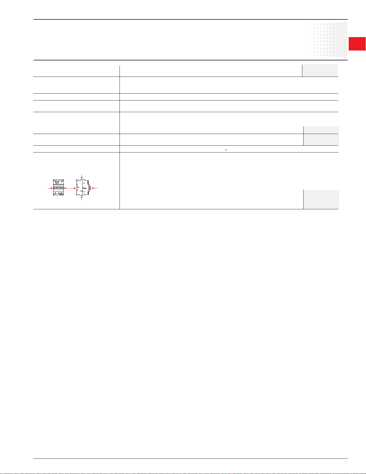
• Categories AC-1 and AC-3: I
• Category AC-2: Ic = 2.5 x I
• Category AC-4: Ic = 6 x I
Generally speaking Ic = m x Ie where m is a multiple of the load operational current.
On pages 1.66 - 1.71, the curves corresponding to categories AC-1, AC-2, AC-3 and AC-4 represent the electrical durability variation of standard contactors in
relation to the breaking current Ic .
Electrical durability is expressed in millions of operating cycles.
These curves have been plotted for 400 V - 50 Hz 3-phase currents but remain valid up to 690 V - 40 ... 60 Hz provided that a check is carried out to make sure
that at the operational voltage Ue , the current Ie normally drawn by the load does not exceed the value of the contactor rated operational current: Ie / AC-1 for
category AC-1 and Ie / AC-3 for categories AC-3 and AC-4. The values are given for each type of contactor in pages 1.44, 1.45, 1.54, and 1.61 (Technical Data).
Curve Utilization Mode
Electrical durability forecast and contactor selection for categories AC-1, AC-2, AC-3 or AC-4
• Note the characteristics of the load to be controlled:
– Operational voltage ............................................................................................U
– Current normally drawn ......................................................................................Ie (Ue / Ie / kW relation for motors, + page 0/0).
– Utilization category ............................................................................................AC-1, AC-2, AC-3 or AC-4
– Breaking current .................................................................................................Ic = Ie for AC-1 and for AC-3 ; Ic = 2.5 x Ie for AC-2 ; Ic = 6 x Ie for AC-4
• Defi ne the number of operating cycles N required.
• On the diagram corresponding to the operational category, select the contactor with the curve immediately above the intersection point (I
= I
c
e
e
e
e
; N).
c
1
1
Electrical durability forecast and contactor selection for mixed duty motor control: AC-3 (I
and, occasionally, AC-4 (Ic = 6 x Ie) type switching off while "motor accelerating".
• Note the characteristics of the motor to be controlled:
– Operational voltage ............................................................................................U
– Current normally drawn while "motor running" ..................................................Ie (Ue / Ie / kW relation for motors, + 0/0).
– Breaking current for AC-3 ..................................................................................Ic = I
– Breaking current for AC-4 while "motor accelerating" .......................................Ic = 6 x I
– Percentage of AC-4 operations .........................................................................K (on the basis of the total number of operating cycles)
• Defi ne the total number of operating cycles N required.
• Note the smallest contactor rating compatible for AC-3 (U
• For the selected contactor make a note of the following in relation to the voltage using diagram AC-3 page 2/85 and AC-4 page 2/86 or 2/87:
– The number of operating cycles A for I
– The number of operating cycles B for Ic = 6 x Ie (AC-4)
• Calculate the estimated number of cycles N' (N' is always below A)
A
N' =
1 + 0.01 K (A/B - 1)
• If N' is too low in relation to the target N, calculate the estimated number of cycles for a higher contactor rating.
Case of uninterrupted duty.
Among the different utilization categories, the uninterrupted duty implies the following remark. The combinated effect of environmental conditions and the proper
temperature of the product may require some disposals. As a matter of fact, for this duty, the use duration prevails over the number of operating cycles.
For long term service, some verifi cations of preventing maintenance are needed to check the functionality of the concerned product (consult us).
Over a duration of fi ve years, in these conditions the contactor might present high internal resistance. We recommend to change the contactor or change the
contacts.
= Ie (AC-3)
c
/ Ie) on pages 2/62, 2/63, 2/73, and 2/79.
e
= Ie) type switching off while "motor running"
c
e
e
e
Low Voltage Products & Systems 1.69
ABB Inc. • 888-385-1221 • www.abb-control.com 1SXU 000 023 C0201
Page 35

IEC Technical data
1
Across the line
1
contactors
Electrical Durability for AC-1 Utilization Category. Ambient Temperature < 55 °C
Switching non-inductive or slightly inductive loads. The breaking current Ic for AC-1 is equal to the rated operational current of the load.
A9 — AF750
Electrical durability
Millions of
operations
A9
A12
A16
A26
A30
A40
A45
A50
A63
A75
A95
A110
A145
A185
10
5
3
2
1
9
7
5
3
1
9
7
5
3
1
0.5
0.3
0.2
9
7
5
3
1
13579
13579
0.1
10 100 10002 3 5 20 30 50 200 300 500
24
Example:
I
/ AC-1 = 24 A – Electrical durability required = 2 million operations.
c
Using the AC-1 curves above select the A 30 contactor at intersection " " (24 A / 2 million operations).
A300
A 260
A210
13579
AF 400
AF 460
13579
AF 580
AF750
Breaking current I
(A)
c
1.70 Low Voltage Products & Systems
1SXU 000 023 C0201 ABB Inc. • 888-385-1221 • www.abb-control.com
Page 36
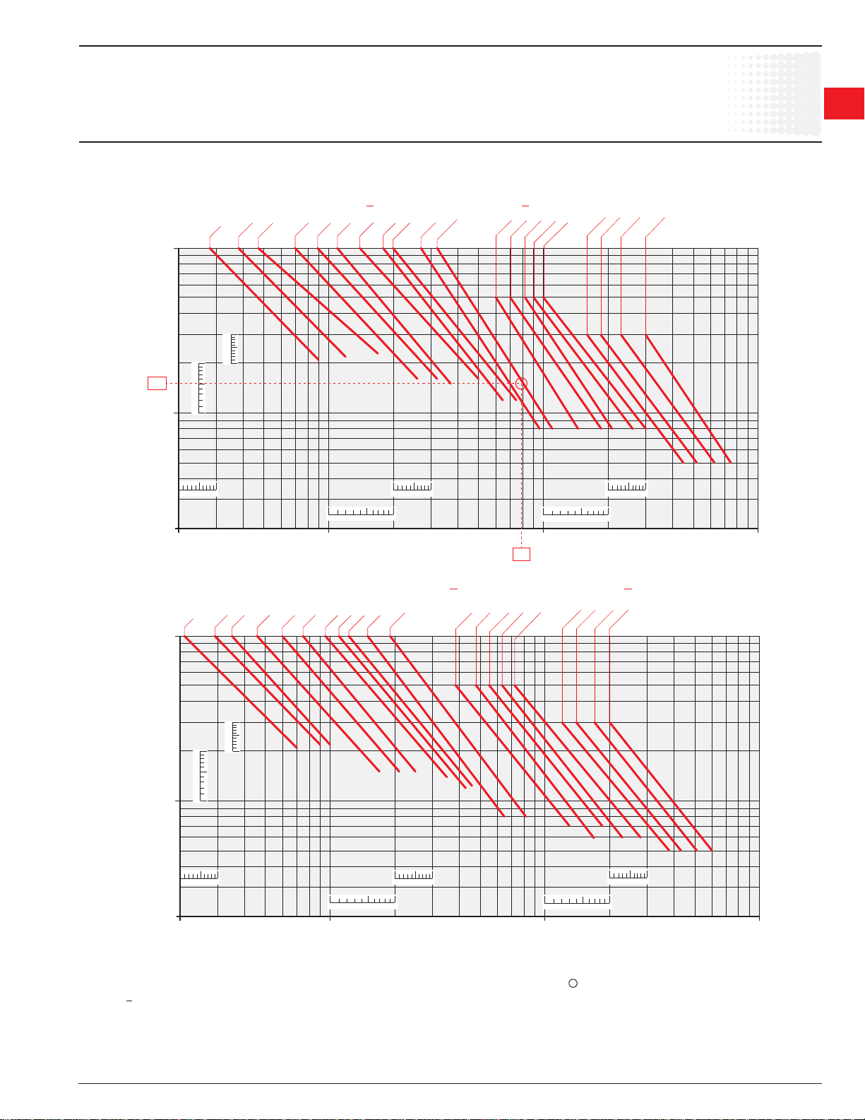
IEC Technical data
A9 — AF750
Electrical durability
Across the line
contactors
1
1
Switching cage motors: starting and switching off running motors. The breaking current Ic for AC-3 is equal to the rated operational current I
(Ie = motor full load current).
Electrical Durability for AC-3 Utilization Category - Ue < 440 V. Ambient Temperature < 55 °C
Millions of
operations
A 30
A12
A16
A 9
A26
A40
10
5
3
2
1.5
1
9
7
5
3
1
9
7
5
3
1
0.5
13579 13579
0.3
13579
0.2
10 100 10002 3 5 20 30 50 200 300 500
A 50
A63
A 75
A 95
A110
A145
A 185
79
A210
A260
A300
13579
AF 400
AF 460
13579
AF 580
AF 750
Breaking current I
c
e
(A)
Electrical Durability for AC-3 Utilization Category - 440 V < Ue < 690 V. Ambient Temperature < 55 °C
Millions of
operations
A9
A 12
A16
A26
A30
A40
A50
A63
A 75
A95
A 110
10
5
3
2
1
9
7
5
3
1
9
7
5
3
1
0.5
0.3
13579
13579
13579
0.2
10 100 10002 3 5 20 30 50 200 300 500
Example:
Motor power 40 kW for AC-3 - Ue = 400 V utilization – Electrical durability required = 1.5 million operations.
40 kW, 400 V corresponds to Ie = 79 A. For AC-3: Ic = Ie. Select the A 110 contactor at intersection " " (79 A / 1.5 million operations) on the curves
(AC-3 - U
< 440 V).
e
A145
A 185
A 210
A 260
A 300
13579
AF 400
AF 460
AF 580
AF 750
13579
Breaking current I
c
(A)
Low Voltage Products & Systems 1.71
ABB Inc. • 888-385-1221 • www.abb-control.com 1SXU 000 023 C0201
Page 37

IEC Technical data
1
Across the line
1
contactors
Electrical Durability for AC-2 or AC-4 Utilization Category - Ue < 440 V. Ambient Temperature < 55 °C
Maximum number of AC-2 or AC-4 operations: 300 per hour for A 9 ... A 40 contactors,
150 per hour for A 50 ... A 300 contactors.
Switching cage motors: starting, reverse operation and step-by-step operation. The breaking current I
AC-4, keeping in mind that Ie is the motor rated operational current (Ie = motor full-load current).
A9 — AF750
Electrical durability
is equal to 2.5 x Ie for AC-2 and 6 x Ie for
c
Millions of
operations
A9
A9
A12
A12
A16
A16
A26
A26
A30
A30
A 40
A 40
A 50
A 50
A 63
A 63
A75
A75
A95
A95
A110
A110
A145
A145
A 185
A 185
A 210
A 210
A260
A260
A300
A300
AF 400
AF 460
AF580
AF 750
10
5
3
2
1
9
7
5
3
1
9
7
5
3
1
0.5
9
7
5
3
1
9
7
5
3
1
0.2
0.2
0.3
0.1
0.05
0.03
0.02
0.01
9
7
5
3
1
9
7
5
3
1
13579
13579
13579
13579
13579
0.005
510
510
Example:
Motor power 45 kW for AC-4 - U
45 kW, 400 V corresponds to I
For AC-4: Ic = 6 x Ie = 510 A - Select the A 260 contactor at intersection " " (510 A / 0.2 million operations) on the curves (AC-4 - Ue < 440 V).
= 400 V utilization – Electrical durability required = 0.2 million operations.
e
= 85 A.
e
13579
30001000100102 3 5 20 30 50 200 300 500 2000 5000
Breaking current I
(A)
c
1.72 Low Voltage Products & Systems
1SXU 000 023 C0201 ABB Inc. • 888-385-1221 • www.abb-control.com
Page 38

IEC Technical data
A9 — AF750
Electrical durability
Electrical Durability for AC-2 or AC-4 Utilization Category - 440 V < Ue < 690 V. Ambient Temperature < 55 °C
Maximum number of AC-2 or AC-4 operations: 300 per hour for A 9 ... A 40 contactors,
150 per hour for A 50 ... A 300 contactors.
Switching cage motors: starting, reverse operation and step-by-step operation. The breaking current I
AC-4, keeping in mind that Ie is the motor rated operational current (Ie = motor full-load current).
is equal to 2.5 x Ie for AC-2 and 6 x Ie for
c
Across the line
contactors
1
1
Millions of
operations
A9
A12
A16
A26
A30
A40
A50
A63
A75
A95
A110
A 145
A185
A 210
A 260
A300
AF 400
AF 460
AF 580
AF 750
10
5
3
2
1
9
7
5
3
1
9
7
5
3
1
0.5
0.3
0.2
0.1
9
7
5
3
1
9
7
5
3
1
0.05
0.04
0.03
0.02
0.01
9
7
5
3
1
9
7
5
3
1
13579
13579
13579
13579
0.005
Breaking current I
(A)
c
Example:
Motor power 59 kW for AC-4 - U
As stated on page 0/0: 59 kW, 600 V corresponds to Ie = 71.1 A.
= 600 V utilization – Electrical durability required = 0.04 million operations.
e
For AC-4: Ic = 6 x Ie = 426.6 A - Select the A 145 contactor at intersection " " (427 A / 0.04 million operations) on the curves
(AC-4 - 440 V < Ue < 690 V).
427
13579
13579
50001000100102 3 5 20 30 50 200 300 500 2000 3000
Low Voltage Products & Systems 1.73
ABB Inc. • 888-385-1221 • www.abb-control.com 1SXU 000 023 C0201
Page 39

1
Across the line
1
contactors
IEC Technical data
AL9 — AL40
Electrical durability
Consult
factory
1.74 Low Voltage Products & Systems
1SXU 000 023 C0201 ABB Inc. • 888-385-1221 • www.abb-control.com
Page 40

IEC Technical data
EK110 — EK1000
Electrical durability
Electrical Durability for AC-1 Utilization Category. Ambient Temperature < 55 °C
Switching non-inductive or slightly inductive loads. The breaking current Ic for AC-1 is equal to the rated operational current of the load.
Across the line
contactors
1
1
Millions of
operations
EK 110
EK 150
EK 175
EK 210
10
5
3
2
1
9
7
5
3
1
9
7
5
3
1
0.5
0.3
0.2
9
7
5
3
1
13579
13579
0.1
10 100 100023 5 2030 50
Example:
I
/ AC-1 = 240 A – Electrical durability required = 2 million operations.
c
Using the AC-1 curves above select the EK 370 contactor at intersection " " (240 A / 2 million operations).
EK 550
EK 370
13579
200 300 500
EK 1000
13579
240
Breaking current I
c
(A)
Low Voltage Products & Systems 1.75
ABB Inc. • 888-385-1221 • www.abb-control.com 1SXU 000 023 C0201
Page 41

1
Across the line
1
contactors
A 50-30-00
AF 460-30-11
IEC Technical data
Infl uence of the length of conductors
used in contactor control circuits
Under certain conditions the excessive length of the control circuit conductors may prevent the contactor from carrying
out closing and opening orders.
– no closing: due to excessive voltage drop (in a.c. or d.c.).
– no opening: due to excessive capacitance (in a.c.).
Contactor Closing (contactor with a.c. or d.c. fed control circuit)
The voltage drop is due to the pull-in current (pull-in power) and to the resistance of the control circuit
conductors.
The table and graph below can be used to determine the single length of line feeders (distance between the control device
and the contactor coil) in relation to:
l the coil pull-in consumption.
l the supply voltage.
l the connecting wire cross-sectional area.
The graph has been drawn for a max. line voltage drop of 5 %.
Coil pull-in consumption (average value)
Contactors a.c. control circuit Contactors d.c. control circuit
50 Hz
A 9, 12, 16 70 VA AE 9, 12, 16 90 W
A 26, 30, 40 120 VA AE 26, 30, 40 110 W
A 45, 50, 63, 75 180 VA AE 45, 50, 63, 75 200 W
A 95, 110 450 VA AE 95, 110 400 W
A 145, 185 700 VA BC 9, 16, 18, 25, 30 7 W
A 210, 260, 300 1700 VA
AF 45, 50, 63, 75 210 VA AF 45, 50, 63, 75 190 W
AF 95, 110 350 VA AF 95, 110 400 W
AF 145,185 430 VA AF 145,185 500 W
AF 210, 260, 300 470 VA AF 210, 260, 300 520 W
AF 400, 460 890 VA AF 400, 460 990 W
AF 580, 750 850 VA AF 580, 750 950 W
Permissible single length for the control circuit conductors on contactor closing:
Depending on the coil pull-in power consumption on the supply voltage and on the control circuit conductor cross-sectional area.
25000
40000
20000
30000
20000
10000
10000
5000
5000
single line length in m.
3000
2000
3000
2000
1000
1000
500
500
300
300
200
200
100
100
50
50
30
30
20
20
10
10
5
5
3
2.5
4
4
2.5
Cross-sectional area (Cu) in mm
15000
10000
5000
3000
2000
1000
500
300
200
100
10000
5000
3000
2000
1000
500
300
200
100
50
50
30
30
20
20
10
10
5
5
3
2
3
2
1.5
1.5
13579 13579 13579 13579
1
1
1 10 100 1000 10000
2 3 5 20 30 50 200 300 500 2000 5000
2
70
60 V
48 V
24 V
660V-690V
500 V
380 V -400V
220 V - 230 V
110 V
Coil pull-in consumption: in VA for a.c. fed contactors
in W for d.c. fed contactors
Example:
A 9 contactor
Coil voltage: 230 V 50 Hz, contactor coil pull-in power consumption: 70 VA,
control circuit conductor cross-sectional area: Cu 1.5 mm
2
.
Max. permissible length: 2000 m.
1.76 Low Voltage Products & Systems
1SXU 000 023 C0201 ABB Inc. • 888-385-1221 • www.abb-control.com
Page 42
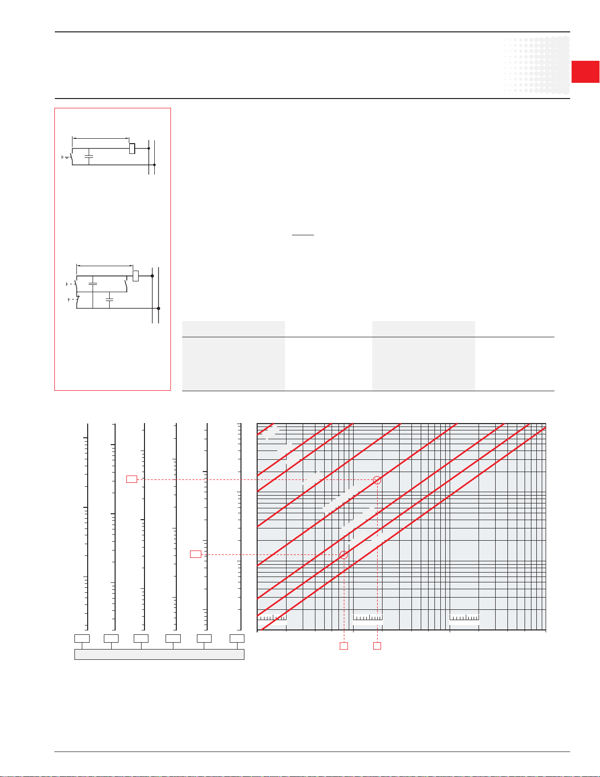
Single control line length
Wiring diagram A
Via maintained pushbutton and 2-core
cable (with a capacity of 0.2 µF/km, for
example).
Single control line length
Wiring diagram B
Via momentary pushbutton plus hold-in
contact and 3-core cable (with a capacity
of 2 x 0.2 = 0.4 µF/km, for example).
Across the line
IEC Technical data
contactors
Infl uence of the length of conductors
used in contactor control circuits
Contactor Opening (contactor with a.c. fed control circuit)
Under certain conditions, an a.c. operated contactor does not open when the control circuit is de-energized.
This is due to a critical capacity of the excessively long control circuit line and the type of contactor coil control layout
(see diagrams A and B opposite).
This may be caused by the following factors:
• high control voltage.
• low coil holding consumption.
• low contactor drop-out voltage (according to IEC 60947-4-1: 0.2 to 0.75 x U
If lines longer than those indicated are required, the following measures must be taken:
• select a contactor with a higher rating.
• select a lower control voltage.
• connect "R
sizing of parallel resistor: R
C
" impedances in parallel with the contactor coil:
P
=
P
3
10
(with C in µF)
The table and graph below can be used to determine the single length of line feeders (distance between the control
device and the contactor coil) in relation to:
• the coil holding consumption VA.
• the supply voltage.
• the capacity in µF/km (depending on the control layout).
Wiring diagrams A and B opposite show two supply and coil control wiring examples.
Coil holding consumption (average value)
Contactors a.c. control circuit Contactors a.c. control circuit
50 Hz 50 Hz
A 9, 12, 16 8 VA AF 45, 50, 63, 75 7 VA
A 26, 30, 40 12 VA AF 95, 110, 7 VA
A 45, 50, 63, 75 18 VA AF 145, 185, 12 VA
A 95, 110 22 VA AF 210, 260, 300 10 VA
A 145, 185 35 VA AF 400, 460 12 VA
A 210, 260, 300 60 VA AF 580, 750 12 VA
).
c
1
1
Permissible single length for the control circuit conductors on contactor opening:
Depending on the coil holding power consumption, on the supply voltage and on the control circuit conductor capacity.
500
300
200
100
10000
5000
3000
2000
1000
500
300
200
5
0.20
100
50
30
20
10
0.10
50
30
20
10
24 V
48 V
60 V
110 V
220 V - 230 V
380V-400V
500 V
660 V - 690V
13579 1357913579
1 10 100 10002 3 5 20 30 50 200 300 500
188
Coil holding consumption in VA
1700
1000
Single line length in metres
500
300
200
100
2500
2000
2000
1000
1000
500
500
380
300
300
200
200
100
50
30
20
10
5
3
2
1.7
0.60
100
50
30
20
10
5
3
2
0.50
Line capacitance inmF/km
3300
2000
1000
500
300
200
100
50
30
20
10
5
2.5
0.40
5000
3000
2000
1000
50
60
30
20
10
5
3.3
0.30
Examples:
A 16 contactor
Coil voltage Uc = 500 V, 50 Hz, 8 VA contactor coil holding consumption, control type: diagram A, via maintained pushbutton, and 2-core
cable with a capacity of 0.2 µF/km.
Max. permissible length: 60 m.
Low Voltage Products & Systems 1.77
ABB Inc. • 888-385-1221 • www.abb-control.com 1SXU 000 023 C0201
A 50 contactor
Coil voltage Uc = 230 V, 50 Hz, 18 VA contactor coil holding consumption, control type: diagram B via momentary pushbutton, hold-in contact and 3-core cable with a capacity of 2 x 0.2 µF/km = 0.4 µF/km.
Max. permissible length: 380 m.
Page 43
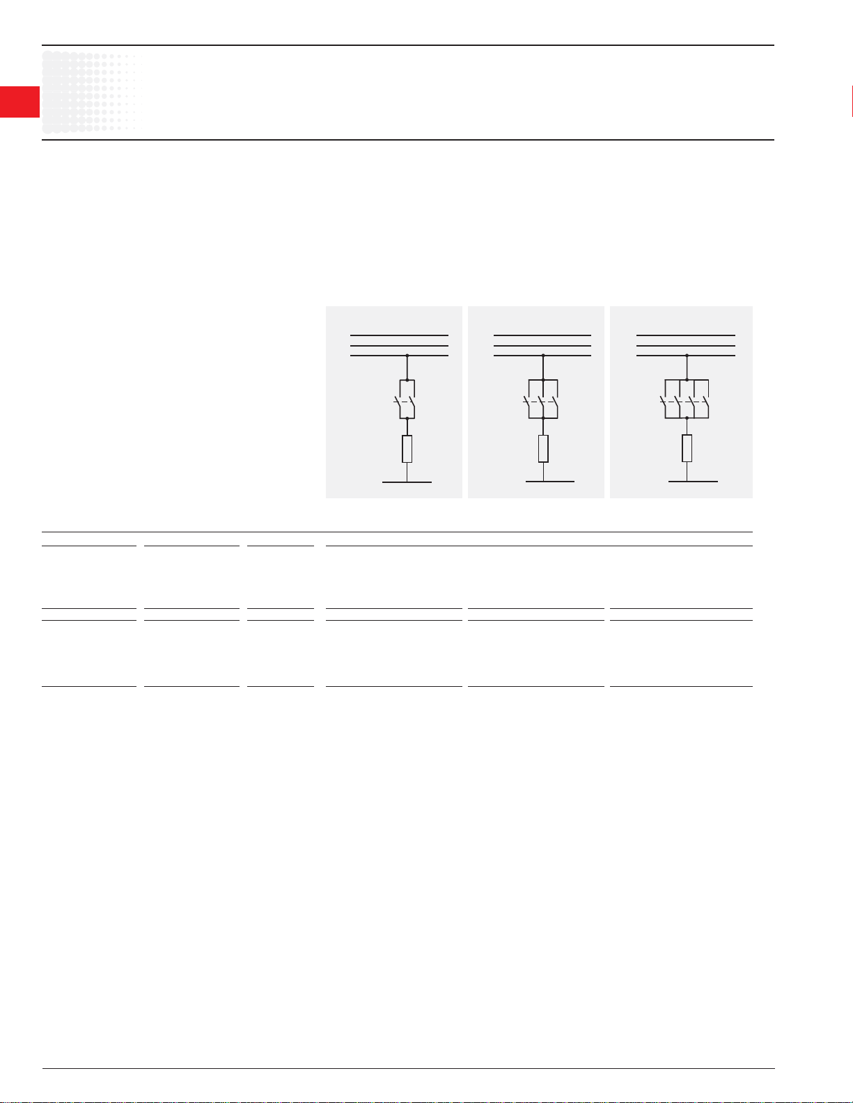
IEC Technical data
1
Across the line
1
contactors
Parallel Connection of Main Poles
Purpose: Increasing the a.c. resistive load.
Remarks:
– Parallel connection of main poles to increase the d.c. resistive load is not acceptable.
– Parallel connection of main poles does'nt increase the breaking capacity.
Means: The poles can be connected in parallel via shorting bars. See page 1.30.
– LP and LH for parallel connection of 2 poles,
– LY and LF for parallel connection of 3 poles,
The table below shows the uprating factor for I
Parallel connection of main poles
/ AC-1 max. in relation to the number of poles in parallel and for a max. switching frequency.
e
L1
L2
L3
N
2 poles in // 3 poles in // 4 poles in //
Contactors Factor to be applied to the rated operational current Ie / AC-1 to obtain the permissible
a.c. Operated d.c. Operated Cycles / h current Ie / AC-1 with "n" poles in parallel.
3-pole contactors
A 9 ... A 75 AF 50 ... AF 75
AF 50 ... AF 75 AE..., TAE... 600 1.6 2.2 –
AL... A 95 ... A 300 AF 145 ... AF 750 300 1.6 2.2 –
AF 145 ... AF 750
4-pole contactors
A 9 ... A 75 AF 45 ... AF 75
AF 45 ... AF 75 AE..., TAE... 600 1.6 2.2 2.6
AL... EK... EK... 300 1.6 2.2 2.8
L1
L2
L3
N
L1
L2
L3
N
1.78 Low Voltage Products & Systems
1SXU 000 023 C0201 ABB Inc. • 888-385-1221 • www.abb-control.com
Page 44

IEC Technical data
Temporary or intermittent duty
Utilization of Contactors for Temporary / Intermittent Duty
The table below shows the factor to be applied to the rated operational current Ie / AC-1 to obtain the permissible operational current Ie / AC-1 in
relation to the switching frequency and the current fl ow time per cycle.
Operating cycles per hour 120 60 20 6 2 1
Current fl ow time Factor to be applied to the rated operational current Ie / AC-1 max.
per cycle in seconds. to obtain the permissible current I
5 2.8 3.4 4 4.7 5 5.2
10 2.2 2.6 3 3.4 3.7 3.8
20 1.6 2 2.4 2.6 2.7 2.8
30 – 1.7 2.1 2.2 2.3 2.4
40 – 1.5 1.9 2.0 2.1 2.2
60 – – 1.7 1.8 1.8 1.9
Example:
A 9 contactor (intermittent duty, resistive load)
Rated operational current I
Switching frequency 2 operations/h
Current fl ow time per cycle 20 s
Factor to be applied to the current I
Permissible current: 2.7 x 22 = 59 A
/ AC-1 at 55 °C (see page 1.42) 22 A
e
/ AC-1 2.7
e
/ AC-1 for temporary / intermittent duty.
e
Across the line
contactors
1
1
Low Voltage Products & Systems 1.79
ABB Inc. • 888-385-1221 • www.abb-control.com 1SXU 000 023 C0201
Page 45

1
Across the line
1
contactors
Technical data
Technical terms and defi nitions
Altitude
Refers to the height of the site where the equipment is located, expressed in
meters above the sea level.
Ambient temperature
Temperature of the air surrounding the unit.
Circuits
• Auxiliary circuit
All the conducting parts of a contactor, intended to be included in a circuit
different from the main circuit and the control circuit of the contactor e.g.
signalization, interlocking circuits etc …
• Control circuit
All the conducting parts of a contactor (other than the main circuit) included in
a circuit used for the closing operation, or opening operation, or both, of the
contactor.
• Main circuit
All the conducting parts of a contactor included in the circuit which it is designed
to close or open.
Coil operating range
Expressed as a multiple of the rated control circuit voltage Uc for the lower and
upper limits.
Cycle duration
Total time of the on-load + off-load period.
Endurance / durability
• Electrical endurance
Number of on-load operating cycles (i.e. with current on the main contacts) a
contactor can achieve, varies depending on the utilization category.
• Mechanical endurance
Number of off-load operating cycles (i.e. without current on the main contacts) a
contactor can achieve.
Inching
Energizing a motor once or repeatedly for short periods to obtain small
movements of the driven mechanism.
Insulation class according to the VDE 0110 and NFC 20-040
Characterizes contactors suitability in accordance with environment and
utilization conditions. A contactor can be classifi ed depending on its own
clearance and creepage distances in the insulation classes A, B, C, D which
correspond to different insulation voltage values.
The insulation class C is applicable to most of the industrial applications.
Equipment described in this catalogue correspond to insulation class C.
Intermittent duty
Duty in which the main contacts of a contactor remain closed for periods of time
insuffi cient to allow the contactor to reach thermal equilibrium, the currentcarrying periods being separated by off-load periods of suffi cient duration to
restore equality of temperature with the cooling medium.
Mounting positions
Stated by the manufacturer. Please note restrictions when applicable.
On-load factor
Ratio of the current fl ow time to the total time of the cycle x 100.
Plugging
Stopping or reversing a motor quickly by interchanging two supply leads whilst
the motor is running.
Rated breaking capacity; Rated making capacity
Value of r.m.s current a contactor can break or make at a fi xed voltage value,
within the conditions specifi ed by the standards, depending on the utilization
category.
Rated control circuit voltage Uc
Control voltage value for which the control circuit of the unit is sized.
Rated insulation voltage U
Voltage value which designates the unit and to which dielectric tests, clearance
and creepage distances are referred.
Rated impulse withstand voltage U
The highest peak value of an impulse voltage of prescribed form 1.2/50, which
does not cause breakdown under specifi ed conditions of test.
Rated operating current I
Current value stated by the manufacturer and taking into account the rated
operating voltage Ue, the rated frequency, the rated duty, the utilization category,
the electrical contact life and the type of the protective enclosure.
Rated operating voltage U
Voltage value to which utilization characteristics of the contactor are referred, i.e.
phase to phase voltage in 3 phase circuits.
Conventional thermal current I
Value of current the contactor can withstand with poles in closed position, in
free air for an eight hour duty, without the temperature rise of its various parts
exceeding the limits specifi ed by the standards.
i
imp
e
e
th
Resistance to shocks
Requirements applicable for instance to vehicles, crane operation or switchgear
slide-in module systems.
At the quoted permissible «g» values, contactors must not undergo a change in
switching state and O/L relays must not trip.
Resistance to vibrations
Requirements applicable to all the vehicles, vessels and other similar transport
systems. At the quoted amplitude and vibration frequency values, the unit must
be capable to achieve the required duty.
Short-circuit protection co-ordination
Achieved by using back-up protection devices such as circuit-breakers, H.R.C.
fuses or standard fuses.
Co-ordination types a, b, c are defi ned in IEC 292-1 publication, VDE 0660, NFC
63-650 standards. Co-ordination types "1" and "2" are defi ned in IEC 947-4-1.
• Type 1 co-ordination
There has been no discharge of parts beyond the enclosure. Damage to the
contactor and the overload relay is acceptable.
• Type 2 co-ordination
No damage to the overload relay or other parts has occured, except that welding
of contactor or starter contacts is permitted, if they are easily separated.
Switching frequency
Number of operating cycles per hour.
Time
• Closing time
Time between energization of the coil until the moment the contacts of the fi rst
current path to be closed actually close.
• Opening time
Time from the beginning of state causing breaking until the moment when the
contacts of the last current path to be opened are open.
• Minimal operation time
Shortest control duration to ensure complete closing or opening of a contactor.
• Short time current permissible
Value of current which the contactor can withstand in closed position for a short
time period and within specifi ed conditions.
• Time constant
Ratio of inductance to the resistance : L/R = mH/Ohm = ms.
1.80 Low Voltage Products & Systems
1SXU 000 023 C0201 ABB Inc. • 888-385-1221 • www.abb-control.com
Page 46

Across the line
IEC Technical data
contactors
Standards, utilization categories
1
Standards
• IEC standards 158-1: “Contactors” and series IEC 292 :
“Motor-starters” have been revised and replaced by the new IEC 947-4-1 (1990-05): “Contactors and Motor-starters” referring to IEC 947-1 (1988): “General rules”
The new standards will constitute the basis of the future European and National standards, not yet revised.
Therefore the ratings indicated in this catalog are established according to the former and the future standards.
• Main changes and additions in the new standards are:
• Revision and extension of the utilization categories (see hereafter)
• Replacement of the coordination classes types a, b, c by new types: “1” (approximately equivalent to former class “a”) and “2” (approximately equivalent to former
class “c”) with additional requirements.
• Classifi cation of the thermal overload relays in tripping classes: 10 A; 10; 20 and 30 depending on their tripping times, at 1.5 and 7.2 times their setting current, in order
to cover motor applications depending on their starting times. Class 10 A is adapted for motors according to IEC 34-1.
• Introduction of tests to verify the connecting capability and the mechanical strength of terminals.
Utilization categories
A contactor duty is characterized by the utilization category plus indication of the rated operating voltage and the rated operating current (see at Rated …), or the motor
characteristics.
Utilization categories for contactors according to IEC 947-4-1
Alternating current: AC-1 Non-inductive or slightly inductive loads, resistance furnaces. Power factor 0.7 - 0.8 (slightly inductive).
AC-2 Slip-ring motors: starting, switching-off.
AC-3 Squirrel-cage motors: starting, switching-off motors during running. Power factor 0.4 - 0.5 (AC-3).
AC-4 Squirrel-cage motors: starting, plugging, inching.
AC-5a Switching of electric discharge lamp controls.
AC-5b Switching of incandescent lamps.
AC-6a Switching of transformers.
AC-6b Switching of capacitor banks
AC-8a Hermetic refrigerant compressor motor control with manual resetting of overload releases
AC-8b Hermetic refrigerant compressor motor control with automatic resetting of overload releases.
Direct current: DC-1 Non-inductive or slightly inductive loads, resistance furnaces.
DC-3 Shunt motors: starting, plugging, inching. Dynamic breaking of d.c. motors.
DC-5 Series motors: starting, plugging, inching. Dynamic breaking of d.c. motors.
DC-6 Switching of incandescent lamps
1
Utilization categories for contactor relays according to IEC 947-5-1
Alternating current: AC-12 Control of resistive loads and solid state loads with isolation by opto couplers.
AC-13 Control of solid state loads with transformer isolation.
AC-14 Control of small electromagnetic loads (≤ 72 VA).
AC-15 Control of electromagnetic loads (> 72 VA).
Direct current: DC-12 Control of resistive loads and solid state loads with isolation by opto couplers.
DC-13 Control of electromagnets.
DC-14 Control of electromagnetic loads having economy resistors in circuit.
Utilization categories AC-1, AC-2, AC-3, AC-4 and DC-1, DC-3, DC-5 are maintained with slightly more severe tests.
Other categories have been added in order to standardize specifi c applications. In fact some contactor applications and the specifi c criteria characterizing the types of
load controlled can modify the recommended utilization characteristics. These major applications are, for example :
Switching of capacitor banks
This application is characterized by high current peaks when switching-on the contactor and presence of harmonic currents on uninterrupted duty. For this application,
IEC 947-4-1 has defi ned an utilization category AC-6b. Practical ratings have to be defi ned according to tests or, in absence of tests, by a calculation indicated in IEC
947-4-1.
Switching of transformers
This application is characterized by high current peaks on contactor closing due to magnetization phenomena. The corresponding utilization category according to IEC
947-4-1 is AC-6a. Ratings are derived from test-values for AC-3 or AC-4 according to formula given in IEC 947-4-1.
Switching of lighting circuits
The current peaks on contactor closing and power factor vary depending on the type of lamps, the switching method used and if compensation systems are fi tted or
not.
IEC 947-4-1 contains two standard utilization categories
AC-5a for switching of the electric discharge lamps.
AC-5b for switching of incandescent lamp.
Low Voltage Products & Systems 1.81
ABB Inc. • 888-385-1221 • www.abb-control.com 1SXU 000 023 C0201
Page 47

UL/CSA Technical data
1
Across the line
1
contactors
Ampere ratings of 3 phase, AC induction motors
110 – 120V 200 – 208V 220 – 240V 380 – 415V1 440 – 480V 550 – 600V
Horse Single Two Three Single Two Three Single Two Three Single Three Single Two Three Single Two Three
power phase phase phase phase phase phase phase phase phase phase phase phase phase phase phase phase phase
1/10 3.0 — — 1.65 — — 1.5 — — 1.0 — — — — — — —
1/8 3.8 — — 2.1 — — 1.9 — — 1.2 — — — — — — —
1/6 4.4 — — 2.4 — — 2.2 — — 1.4 — — — — — — —
1/4 5.8 — — 3.2 — — 2.9 — — 1.8 — — — — — — —
1/3 7.2 — — 4.0 — — 3.6 — — 2.3 — — — — — — —
1/2 9.8 4.0 4.4 5.4 2.2 2.4 4.9 2.0 2.2 3.2 1.3 2.5 1.0 1.1 2.0 0.8 0.9
3/4 13.8 4.8 6.4 7.6 2.6 3.5 6.9 2.4 3.2 4.5 1.8 3.5 1.2 1.6 2.8 1.0 1.3
1 16.0 6.4 8.4 8.8 3.6 4.6 8.0 3.2 4.2 5.1 2.3 4.0 1.6 2.1 3.2 1.3 1.7
1 1/2 20.0 9.0 12.0 11.0 5.0 6.6 10.0 4.5 6.0 6.4 3.3 5.0 2.3 3.0 4.0 1.8 2.4
2 24.0 11.8 13.6 13.2 6.5 7.5 12.0 5.9 6.8 7.7 4.3 6.0 3.0 3.4 4.8 2.4 2.7
3 34.0 16.6 19.2 18.7 9.2 10.6 17.0 8.3 9.6 10.9 6.1 8.5 4.2 4.8 6.8 3.3 3.9
5 56.0 26.4 30.4 30.8 14.5 16.8 28.0 13.2 15.2 17.9 9.7 14.0 6.6 7.6 11.2 5.3 6.1
7 1/2 80.0 38.0 44.0 44.0 21.0 24.2 40.0 19.0 22.0 27.0 14.0 21.0 9.0 11.0 16.0 8.0 9.0
10 100.0 48.0 56.0 55.0 26.4 30.8 50.0 24.0 28.0 33.0 18.0 26.0 12.0 14.0. 20.0 10.0 11.0
15 135.0 72.0 84.0 75.0 39.6 46.2 68.0 36.0 42.0 44.0 27.0 34.0 18.0 21.0 27.0 14.0 17.0
20 — 94.0 108.0 96.8 52.0 60.0 88.0 47.0 54.0 56.0 34.0 44.0 23.0 27.0 35.0 19.0 22.0
25 — 118.0 136.0 121.0 65.0 75.0 110.0 59.0 68.0 70.0 44.0 55.0 29.0 34.0 44.0 24.0 27.0
30 — 138.0 160.0 150.0 76.0 88.0 136.0 69.0 80.0 87.0 51.0 68.0 35.0 40.0 54.0 28.0 32.0
40 — 180.0 208.0 194.0 100.0 115.0 176.0 90.0 104.0 112.0 66.0 88.0 45.0 52.0 70.0 36.0 41.0
50 — 226.0 260.0 238.0 125.0 143.0 216.0 113.0 130.0 139.0 83.0 108.0 56.0 65.0 86.0 45.0 52.0
60 — — — — 147.0 160.0 — 133.0 154.0 — 103.0 — 67.0 77.0 — 53.0 62.0
75 — — — — 183.0 212.0 — 166.0 192.0 — 128.0 — 83.0 96.0 — 66.0 77.0
100 — — — — 240.0 273.0 — 218.0 248.0 — 165.0 — 109.0 124.0 — 87.0 99.0
125 — — — — — 344.0 — — 312.0 — 208.0 — 135.0 156.0 — 108.0 125.0
150 — — — — — 396.0 — — 360.0 — 240.0 — 156.0 180.0 — 125.0 144.0
200 — — — — — 528.0 — — 480.0 — 320.0 — 208.0 240.0 — 167.0 192.0
250 — — — — — 663.0 — — 602.0 — 403.0 — — 302.0 — — 242.0
300 — — — — — — — — — — 482.0 — — 361.0 — — 289.0
350 — — — — — — — — — — 560.0 — — 414.0 — — 336.0
400 — — — — — — — — — — 636.0 — — 477.0 — — 382.0
500 — — — — — — — — — — 786.0 — — 590.0 — — 472.0
Motor data
1 To obtain full load currents for 265V and 277V motors, decrease corresponding 220 – 240V ratings by 13 percent and 17 percent.
1.82 Low Voltage Products & Systems
1SXU 000 023 C0201 ABB Inc. • 888-385-1221 • www.abb-control.com
Page 48

Approximate dimensions
3 pole contactors, A/AE9 – A/AE26
00.00
00.00
A/AE9 – A/AE16 — Contactor, 3 pole
Inches
[Millimeters]
1.73
44
2.91
74
2.68
68
0.22
5.5
1.38
35
Across the line
contactors
1
1
2.91
74
A/AE9 – A/AE16 + VM5 or VE5 — Mechanically interlocked contactor, 3 pole
2.91
74
2.68
68
0.22
5.5
2.91
74
5.50
139.7
4.06
103
A/AE26 — Contactor, 3 pole
3.69
93.6
3.44
87.3
0.35
9
3.54
90
2.13
54
2.36
60
0.18
60
0.18
4.5
1.38
4.5
2.76
70
1.972.36
50
1.77
45
2.32
59
3.15
80
1.97
50
35
0.17
4.2
A/AE26 + VM5 or VE5 — Mechanically interlocked contactor, 3 pole
4.03
102
3.69
93.6
3.44
87.3
0.35
9
4.64
117.9
5.25
133.4
3.54
90
5.25
133.4
4.84
123.0
Low Voltage Products & Systems 1.83
ABB Inc. • 888-385-1221 • www.abb-control.com 1SXU 000 023 C0201
2.32
1.77
45
4.64
117.9
0.22
59
0.17
4.2
2.72
69
5.5
2.76
70
3.15
80
Page 49

1
5
5
Across the line
1
contactors
Approximate dimensions
3 pole , A/AE30 – A/AE/AF75
00.00
00.00
Inches
[Millimeters]
A/AE30 & A/AE40 — Contactor, 3 pole
3.54
90
2.13
54
4.26
108.3
4.02
102
0.35
9
A/AE30 & A/AE40 + VM5 or VE5 — Mechanically interlocked contactor, 3 pole
4.60
117
4.26
108.3
4.02
102
0.35
9
5.25
133.4
3.54
90
5.25
133.4
4.84
123.0
A/AE/AF50 – A/AE/AF75 — Contactor, 3 pole
4.25
108
3.22
2.76
82
70
4.00
101.5
0.39
10
0.17
4.2
2.76
4.64
117.9
1.77
45
3.1
2.32
59
45
2.36
60
4.64
117.9
80
0.22
5.5
2.76
3.1
70
80
0.17
4.2
2.72
69
70
1.77
4.33
110
3.94
100
0.24
6.2
3.54
90
A/AE/AF50 – A/AE/AF75 + VM5 or VE5 — Mechanically interlocked contactor, 3 pole
4.54
115.3
4.25
108
4.00
101.5
0.39
10
5.87
149
3.00
76.3
6.50
165
4.33
110
6.62
168.2
6.10
155
1.84 Low Voltage Products & Systems
1SXU 000 023 C0201 ABB Inc. • 888-385-1221 • www.abb-control.com
6.00
152.5
0.22
5.5
3.54
90
3.94
100
0.24
6.2
Page 50

Approximate dimensions
3 pole, A/AE/AF95 & A/AE/AF110
00.00
00.00
A/AE/AF95 & A/AE/AF110 — Contactor, 3 pole
A/AE/AF95 & A/AE/AF110 + VE5 — Mechanically interlocked contactor, 3 pole
Inches
[Millimeters]
8.70
221
7.68
195
5.17
131
4.86
123.5
0.39
10
3.90
99
7.91
200.1
Across the line
contactors
1
0.31
8
1
8.10
205.7
4.33
148
7.28
185
3.07
78
0.24
6.2
4.13
105
4.96
126
5.35
136
Low Voltage Products & Systems 1.85
ABB Inc. • 888-385-1221 • www.abb-control.com 1SXU 000 023 C0201
Page 51

1
7
5
Across the line
1
contactors
Approximate dimensions
4 pole contactors, A/AE9 – A/AE/AF75
00.00
00.00
Inches
[Millimeters]
A/AE9 – A/AE16 — Contactor, 4 pole
1.73
44
2.91
74
A/AE26 — Contactor, 4 pole
2.13
54
3.54
90
A/AE/AF45 – A/AE/AF75 — Contactor, 4 pole
3.62
92
4.71
119.5
4.45
113
2.91
74
2.68
68
0.22
3.69
93.6
3.44
87.3
5.5
0.35
0.39
1.38
35
1.77
45
1.9
50
3.1
80
3.23
82
2.36
60
0.18
4.5
9
2.76
70
0.17
4.2
10
3.54
4.33
110
3.94
100
0.24
6.2
90
1.86 Low Voltage Products & Systems
1SXU 000 023 C0201 ABB Inc. • 888-385-1221 • www.abb-control.com
Page 52

Approximate dimensions
3 & 4 pole contactors, AL9 – AL40
00.00
00.00
AL9, AL12,, AL16 — Contactor, 3 & 4 pole
AL26 — Contactor, 3 & 4 pole
Inches
[Millimeters]
Across the line
contactors
1
1
AL30, AL40 — Contactor, 3 pole
Low Voltage Products & Systems 1.87
ABB Inc. • 888-385-1221 • www.abb-control.com 1SXU 000 023 C0201
Page 53

1
Across the line
1
contactors
A/AE9 – A/AE40
A/AE/AF50 – A/AE/AF110
Approximate dimensions
Accessories for A/AE9 – A/AE/AF110
00.00
00.00
Inches
[Millimeters]
A
SIDE MOUNTED
AUXILIARY
D
ON-POSITION
LATCH
TYPE
A/AE9-16
A/AE26
A/AE30-40
A/AE/AF50-75
A/AE/AF45
A/AE/AF95-110
B
SINGLE POLE
TOP MOUNTED
AUXILIARY
PNEUMATIC
A
IN
MM
2.20
INMM2.20564.72
INMM2.20565.30
INMM3.23825.27
INMM4.09
INMM4.02
56
104
102
3.96
100.5
119.8
134.5
133.9
5.73
145.5
5.91
TIMER
B
150
C
FOUR POLE
TOP MOUNTED
AUXILIARY
E
C
4.21
107
4.97
126.3
5.55
141
5.52
140.3
5.98
152
6.16
156.5
D
5.71
145
6.47
164.3
7.05
179
7.03
178.5
7.48
190
–
–
E
5.00
127
5.76
146.3
6.34
161
6.32
160.4
6.77
172
–
–
F
MECH INTERLOCK D.C.
OPERATED
F
–
–
–
–
–
–
–
–
–
–
–
–
1.88 Low Voltage Products & Systems
1SXU 000 023 C0201 ABB Inc. • 888-385-1221 • www.abb-control.com
Page 54

Approximate dimensions
A/AF145 – A/AF185
00.00
00.00
A/AF145 & A/AF185
A/AF145, A/AF185 with mechanical interlock
Inches
[Millimeters]
Across the line
contactors
1
1
A/AF145, A/AF185 reversing
Low Voltage Products & Systems 1.89
ABB Inc. • 888-385-1221 • www.abb-control.com 1SXU 000 023 C0201
Page 55

Approximate dimensions
1
Across the line
1
contactors
A/AF145 – A/AE/AF95-110 mechanically interlocked
A/AF145 – A/AF300
00.00
00.00
Inches
[Millimeters]
A/AF210, A/AF260, A/AF300
1.90 Low Voltage Products & Systems
1SXU 000 023 C0201 ABB Inc. • 888-385-1221 • www.abb-control.com
Page 56

Approximate dimensions
A/AF210 – A/AF300
00.00
00.00
A/AF210, A/AF260, A/AF300 with mechanical interlock
A/AF210, A/AF260, A/AF300 reversing +TA450
Inches
[Millimeters]
Across the line
contactors
1
1
A/AF210, A/AF145 with mechanical interlock
Low Voltage Products & Systems 1.91
ABB Inc. • 888-385-1221 • www.abb-control.com 1SXU 000 023 C0201
Page 57

1
Across the line
1
contactors
AF400, AF460
Approximate dimensions
AF400 – AF460
00.00
00.00
Inches
[Millimeters]
AF400, AF460 with mechanical interlock
1.92 Low Voltage Products & Systems
1SXU 000 023 C0201 ABB Inc. • 888-385-1221 • www.abb-control.com
Page 58
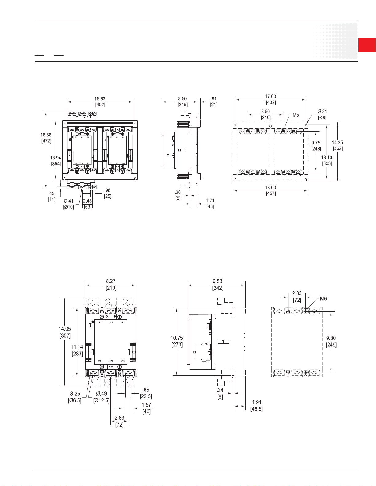
00.00
00.00
AF400, AF460 reversing
Inches
[Millimeters]
Approximate dimensions
AF400 – AF750
Across the line
contactors
1
1
AF580 – AF750
Low Voltage Products & Systems 1.93
ABB Inc. • 888-385-1221 • www.abb-control.com 1SXU 000 023 C0201
Page 59

Approximate dimensions
1
Across the line
1
contactors
AF580 – AF750 with mechanical interlock
AF580 – AF750
00.00
00.00
Inches
[Millimeters]
AF580 – AF750 reversing
1.94 Low Voltage Products & Systems
1SXU 000 023 C0201 ABB Inc. • 888-385-1221 • www.abb-control.com
Page 60

00.00
00.00
AF1350 – AF1650
Inches
[Millimeters]
Approximate dimensions
AF1350 – AF1650
;=
Across the line
contactors
1
1
Low Voltage Products & Systems 1.95
ABB Inc. • 888-385-1221 • www.abb-control.com 1SXU 000 023 C0201
Page 61
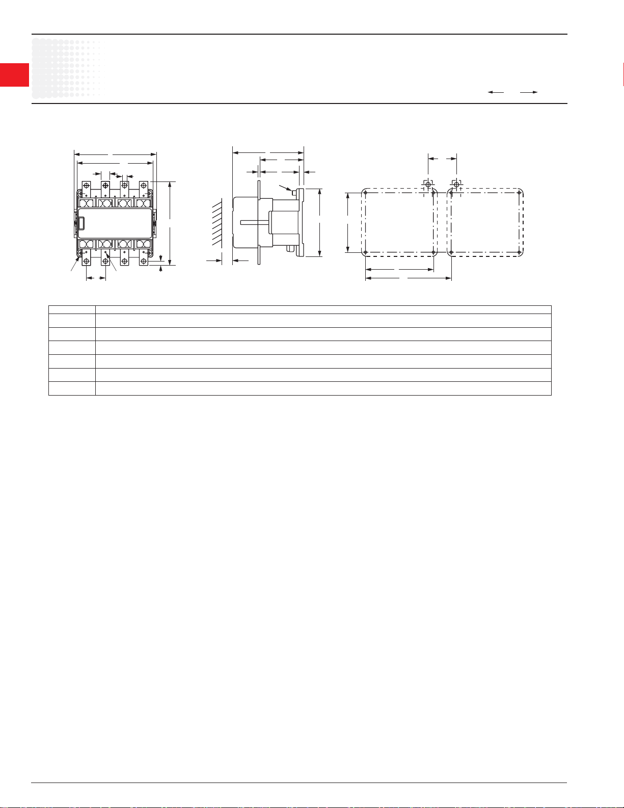
1
Across the line
1
contactors
Approximate dimensions
EK110 – EK550, 4 pole, non-reversing
00.00
00.00
Inches
[Millimeters]
M6 M4
mm
mm
mm
mm
mm
mm
in
in
in
in
in
in
EK 110
EK 150
EK 175
EK 210
EK 370
EK 550
EK 1000
B
B1
DG
P
P1
T1
T
F1
PE
C1
1.69
1.65
2.64
2.64
2.76
2.76
H
C
C2
G
F1
0.59
43
0.79
42
0.79
67
0.79
67
0.98
70
0.98
70
H
6.14
6.14
156
15
20
20
20
25
25
6.14
156
6.14
156
6.14
156
8.78
223
8.78
223
6.77
7.80
7.80
10.71
10.71
156
172
198
198
272
272
K1H1
0.30
7.5
0.39
10
0.39
10
0.39
10
0.49
12.5
0.49
12.5
PP1T
6.08
154.5
6.08
154.5
6.77
172
6.77
172
8.88
225.5
8.88
225.5
4.03
102.3
4.03
102.3
4.20
106.7
4.20
106.7
5.49
139.5
5.49
139.5
0.39
10
0.39
10
0.39
10
0.39
10
0.91
23
0.91
23
T1
0.16
4
0.16
4
0.20
5
0.20
5
0.24
6
0.24
6
H1
E
B1
5.35
136
5.35
136
6.93
176
6.93
176
9.61
244
9.61
244
K1
4.72
120
4.72
120
6.30
160
6.30
160
8.66
220
8.66
220
C1
C
5.51
140
5.51
140
5.51
140
5.51
140
7.87
200
7.87
200
0.26
0.43
0.43
0.43
0.43
0.43
E
D
6.6
11
11
11
11
11
1,57
40
1.57
40
0.59
15
0.59
15
1.57
40
1.57
40
F
1.61
41
1.65
42
1.77
45
1.77
45
2.64
67
2.64
67
F
B
6.50
165
6.50
165
7.91
201
7.91
201
10.63
270
10.63
270
1.96 Low Voltage Products & Systems
1SXU 000 023 C0201 ABB Inc. • 888-385-1221 • www.abb-control.com
 Loading...