

Page 1
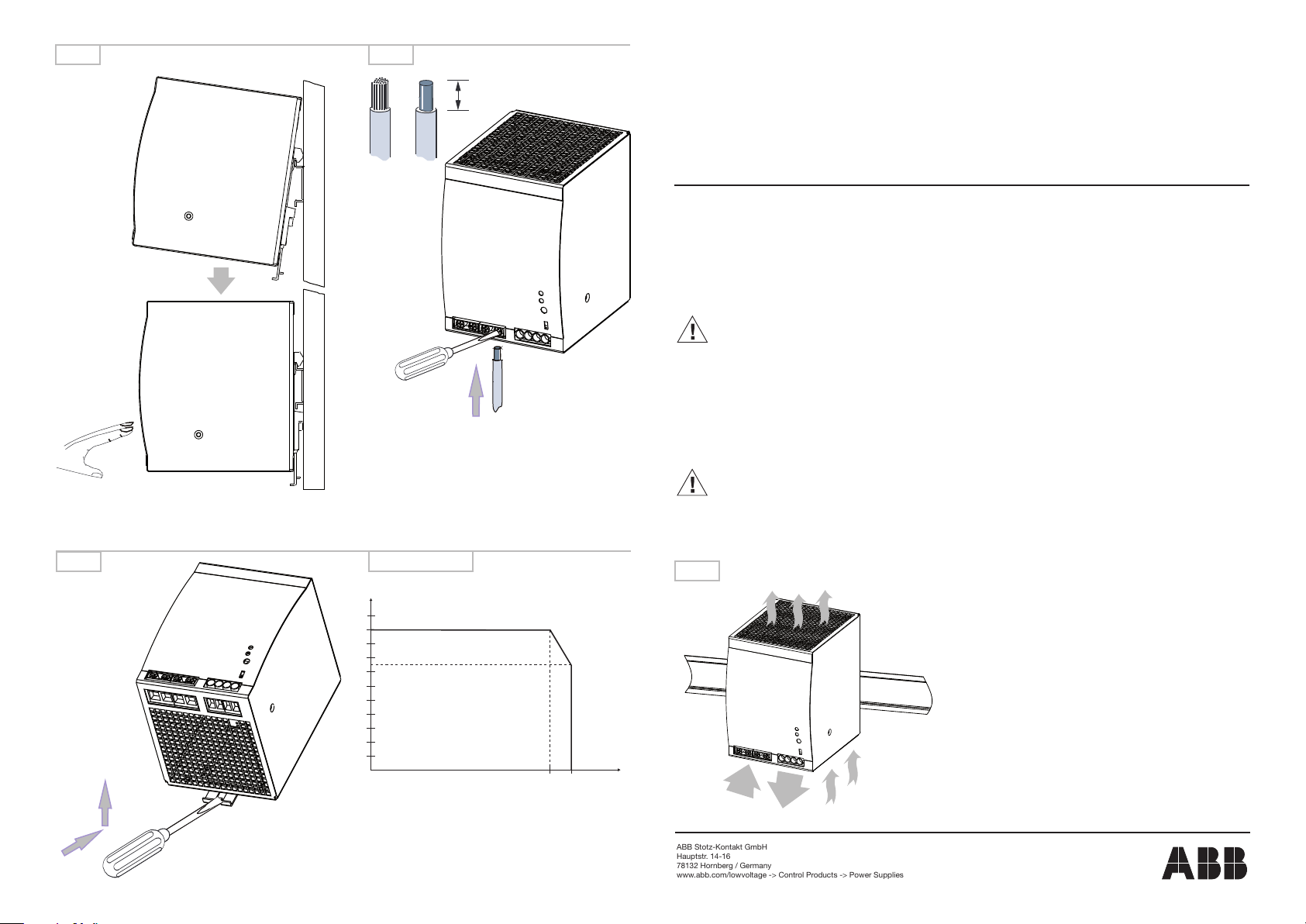
Fig. 2 Fig. 3
Connector size range:
Fine strand with ferrule 0.2 ... 4.0 mm² / 24 ... 11 AWG
Rigid 0.2 ... 6.0 mm² / 24 ... 10 AWG
Tightening torque of input connector:
Max. 1 Nm / 9 in.lb
Tightening torque of output connector:
Max. 0.6 Nm / 5.5 in.lb
Use copper conductors 60/75 °C only
8 mm
Primary switch mode power supplies
CP-T 24/10.0
CP-T 48/5.0
Betriebs- und Montageanleitung
Primär getaktete Schaltnetzteile CP-T Reihe
Hinweis: Diese Betriebs- und Montageanleitung enthält nicht sämtliche Detailinformationen zu allen Typen der Produktreihe und kann
auch nicht jeden Einsatzfall der Produkte berücksichtigen. Alle Angaben dienen ausschließlich der Produktbeschreibung und sind nicht
als zugesicherte Eigenschaften im Rechtssinne aufzufassen. Weiterführende Informationen und Daten erhalten Sie in den Katalogen und
Datenblättern der Produkte, über die örtliche ABB-Niederlassung sowie auf der ABB Homepage unter http://www.abb.com. Technische
Änderungen jederzeit vorbehalten. In Zweifelsfällen gilt der deutsche Text.
Nur von einer entsprechend qualifizierten Fachkraft zu installieren. Dabei landesspezifische Vorschriften (z.B. VDE, etc.)
beachten. Vor der Installation diese Betriebs- und Montageanleitung sorgfältig lesen und beachten. Die Geräte sind wartungsfreie Einbaugeräte.
Operating and installation instructions
Primary switch mode power supplies CP-T range
Note: These operating and installation instructions cannot claim to contain all detailed information of all types of this product range and
can even not consider every possible application of the products. All statements serve exclusively to describe the product and have
not to be understood as assured characteristics with legal force. Further information and data is obtainable from the catalogues and
data sheets of this product, from the local ABB sales organisations as well as on the ABB homepage http://www.abb.com. Subject to
change without prior notice. The German text applies in cases of doubt.
The device must be installed by qualified persons only and in accordance with the specific national regulations (e.g., VDE,
etc.). Before installing this unit, read these operating and installation instructions carefully and completely. The devices are
maintenance-free chassis-mounted units.
Fig. 4
Fig. 5 Derating
P
[%]
out
100
90
80
70
60
50
40
30
20
10
-25 60 70
Fig. 1
Input
[°C]
T
a
2CDC 272 011 F0208
1SVC 427 050 M0000 A2 (03/10)
ABB Stotz-Kontakt GmbH
Hauptstr. 14-16
78132 Hornberg / Germany
www.abb.com/lowvoltage -> Control Products -> Power Supplies
Output
ADDITIONAL INFORMATION
RELATING TO UL APPROVALS
FOR USE IN POLLUTION DEGREE 2 ENVIRONMENT
ACCORDING TO ANSI-ISA 12.12:
THIS EQUIPMENT IS SUITABLE FOR USE IN CLASS I, DIVISION 2,
GROUPS A, B, C, and D OR NON-HAZARDOUS LOCATIONS ONLY.
WARNING - EXPLOSION HAZARD - SUBSTITUTION OF COMPONENTS
MAY IMPAIR SUITABILITY FOR CLASS I, DIVISION 2.
WARNING - EXPLOSION HAZARD - DO NOT DISCONNECT EQUIPMENT UNLESS POWER HAS BEEN SWITCHED OFF OR THE AREA IS
KNOWN TO BE NON-HAZARDOUS.
WARNING - EXPOSURE TO SOME CHEMICALS MAY DEGRADE THE
SEALING PROPERTIES OF MATERIALS USED IN THE SWITCHING
ELEMENTS IN THE DEVICE.
Sealed Device: Switch Model ST-22 manufactured by Seki Controls
Company , LTD.
Switch Case: LG Chemical LTD., Type Lupox GP2306FT-NP, PBT Resin
Switch Epoxy: Emerson & Coming, Type ST 2850FT-FRJ-CA9, Epoxy
Resin
We recommend to periodically inspect the device named above for any
degradation of properties and replace if degradation is found.
ACCORDING TO UL 508:
MAX. SURROUNDING AIR TEMPERATURE OF 50 °C
Page 2
Sicherheits- und Warnhinweise:
Anlage freischalten!
Vor Installations-, Wartungs- oder Änderungsarbeiten: Anlage spannungsfrei schalten, vor Wiedereinschalten sichern.
Vor Inbetriebnahme:
Achtung! Unsachgemäße Installation/Betrieb kann die Sicherheit beeinträchtigen und zu Betriebsstörungen oder zur Zerstörung des Gerätes führen. Vor der
Inbetriebnahme ist Folgendes sicherzustellen:
• Netzanschluss gemäß den landesspezifischen Vorschriften durchführen
• Zuleitungen und Gerät ausreichend absichern. Eine Trenneinrichtung für das Netzteil vorsehen, um das Gerät und die Zuleitungen im Bedarfsfall zu unterbrechen
• Schutzleiter an die Klemme anschließen (Schutzklasse I)
• Die Sekundärseite des Netzteils ist nicht geerdet. Sie kann je nach Bedarf (wahlweise L+ oder L-) vom Anwender geerdet werden.
• Ausgangsleitungen für den Ausgangsstrom des Netzteils dimensionieren und polrichtig anschließen.
• Abstände zu benachbarten Geräten beachten um eine ausreichende Kühlung zu gewährleisten
Im Betrieb:
• Keinerlei Änderungen an der Installation (primär- und sekundärseitig) vornehmen! (Starkstrom!). Gefahr von Lichtbögen und elektrischem Schlag (Lebensgefahr!)
• Verbrennungsgefahr: In Abhängigkeit der Betriebsbedingungen kann die Gehäusetemperatur hohe Werte annehmen.
• Die interne Sicherung kann vom Anwender nicht ausgetauscht werden. Löst die interne Sicherung aus, liegt mit hoher Wahrscheinlichkeit ein Gerätedefekt vor.
In diesem Fall ist eine Überprüfung des Netzteiles durch den Hersteller erforderlich.
Achtung: Hochspannung! Gespeicherte Energie! Gefährliche Energie am Ausgang!
In den Netzteilen befinden sich Bauelemente mit hoher gespeicherter Energie und Stromkreise mit Hochspannung! Deshalb keine Gegenstände in das Gerät einführen und das Gerät nicht öffnen. Bei einigen Geräten dieser Serie kann der Ausgang gefährlich hohe Energiemengen abgeben. Sicherstellen, dass Bedienpersonal
vor versehentlicher Berührung energieführender Teile geschützt ist.
Konvektionskühlung:
Die Lüftungsöffnungen nicht bedecken! Um das Gerät herum genügend Platz zur Kühlung lassen! Siehe Fig. 1
Montage:
1. DIN-Schiene (TH 35-15 oder TH 35-7,5 nach IEC/EN 60715) wie in Abbildung 1 dargestellt auf der Montageplatte befestigen, horizontale Einbaulage, Eingangsklemmen unten, auf allen Seiten Mindestabstand von 25 mm zu benachbarten Geräten einhalten.
2. Gerät wie in Abbildung 2 dargestellt auf die DIN-Schiene aufschnappen.
1) Gerät leicht nach oben kippen und auf DIN-Schiene aufsetzen.
2) Bis zum Anschlag nach unten klappen.
3) Unten gegen die Vorderseite drücken, um zu verriegeln. Leicht am Gerät rütteln, um Verriegelung zu überprüfen.
3. Entfernen von der DIN-Schiene wie in Abbildung 4 dargestellt. Isolierten Schraubendreher zur Entriegelung verwenden.
Elektrischer Anschluss (siehe Abbildung 3):
Korrekte Dimensionierung, Abisolierlänge und Anschluss der Kabel sicherstellen.
Frontelemente:
Potentiometer „OUTPUT Adjust“ zum Einstellen der Ausgangsspannung.
Schalter „single/parallel“ zur Einstellung von Einzel- oder Parallelbetrieb.
Meldekontakt 13-14 (max. 60 V DC / 0,3 A): Geschlossen, wenn die Ausgangsspannung größer als 19,4 V ist (nur bei 24 V-Geräten).
Typ grüne LED „OK“: An grüne LED „OK“: Aus rote LED „LOW“: An rote LED „LOW“: Aus
CP-T 24/10.0 M 18,72 V m 18,62 V M 2,31 V M 18,78 V
CP-T 48/5.0 M 39,91 V m 39,81 V M 2,18 V M 40,12 V
Externer Eingangsschutz:
Die Auswahl des externen Schutzelementes muss nach den geltenden nationalen Vorschriften erfolgen. Es ist auch die Spannung zu beachten!
Empfohlener Leitungsschutzschalter, z.B. bei 3 x 400 V, ABB-Type S203-xxB (B-Characteristic) oder S203-xxC (C-Characteristic) mit Nennströmen bis max. 20 A
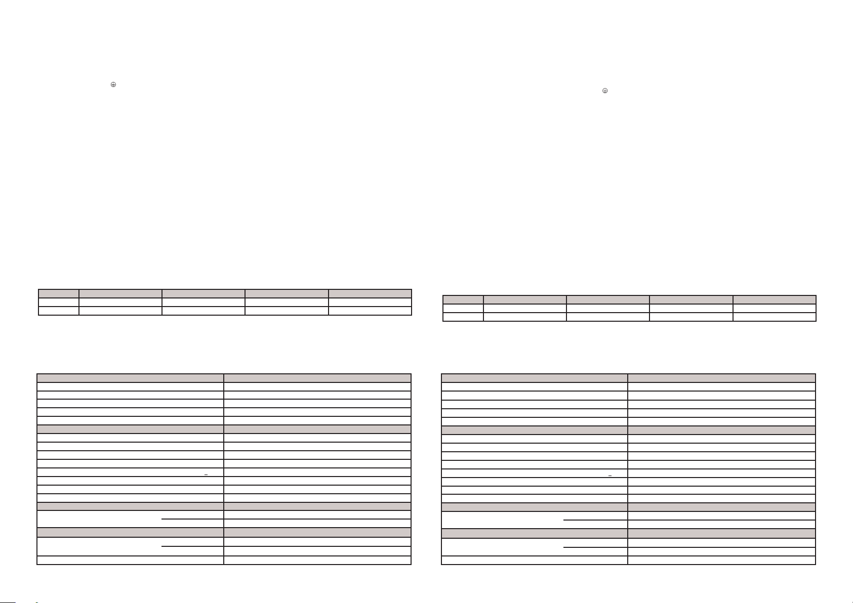
Technische Daten:
Daten bei Tu = 25 °C und Bemessungswerten, sofern nichts anderes angegeben ist.
Eingangskreis
Bemessungseingangsspannung 3 x 400-500 V AC
AC-Eingangsspannungsbereich 340-575 V AC
DC-Eingangsspannungsbereich 480-820 V DC
Frequenzbereich 47-63 Hz
Interne Eingangssicherung 2 A / 600 V AC / Phase
Ausgangskreis
Bemessungsausgangsspannung siehe Leistungsschild
Toleranz der Ausgangsspannung 0...+1 %
Einstellbereich der Ausgangsspannung siehe Leistungsschild
Bemessungsausgangsleistung siehe Leistungsschild
Derating des Ausgangsstromes
Ausgangskennlinie Hiccup-Modus und U/I Kennlinie kombiniert
Leerlaufschutz dauerleerlauffest
Parallelschaltbarkeit zur Leistungserhöhung konfigurierbar, 2 Geräte, Reduktion: (Anzahl Gerät x Ir) x 0,9
Isolationsdaten
Bemessungsisolationsspannung Ein-/ Ausgangskreis 3 kV AC
Allgemeine Daten
Umgebungstemperaturbereich Tu Betrieb / Lagerung -25...+70 °C / -25...+85 °C
Bemessungslast -25...+60 °C
Abmessungen (BxHxT) 89 x 131 x 118,8 mm / 3,5 x 5.16 x 4,68 in
60 °C < Tu < 70 °C siehe Fig. 5
Eingangskreis / PE 1,5 kV AC
CP-T 24/10.0 und CP-T 48/5.0
Safety instructions and warnings:
Disconnect system from supply network!
Before any installation, maintenance or modification work: Disconnect the system from the supply network and protect against switching on.
Before start of operation:
Attention! Improper installation/operation may impair safety and cause operational difficulties or destruction of the unit. Before operation the following must be
ensured:
• Connect to main according t the specific national regulations.
• Power supply cables and unit must be sufficiently fused. A disconnecting device has to be provided for the end product to disengage unit and supply cables
from supply mains if required.
• The protective earth conductor must be connected to the terminal (Protection class I)
• The secondary side of the power supply unit is not earthed and can be earthed by the user according to the needs with L+ or L-.
• Rate the output lines for the output current of the power supply and connect thme with the correct polarity.
• In order to ensure sufficient air-cooling the distance to other devices has to be considered.
In operation:
• Do not modify the installation (primary and secondary side)! High current! Risk of electric arcs and electric shocks (danger to life)!
• Risk of burns: Depending on the operation conditions the enclosure can become very hot.
• The internal fuse is not user-replaceable. If the internal fuse blows, most probably the device is defective. In this case, an examination of the switch mode power
supply by the manufacturer is necessary.
Warning: High voltage! Stored energy! Energy hazard at output!
The power supplies contain components with high stored energy and circuits with high voltage! Do not introduce any objects into the unit, and do not open the unit.
With some units of this range the output is capable of providing hazardous energy. Ensure that the service personnel is protected against inadvertent contact with
parts carrying energy.
Convection cooling:
Do not cover any ventilation holes! Leave sufficient space around the unit for cooling! See Fig. 1
Mounting:
1. Fasten the DIN rail (TH 35-15 or TH 35-7,5 according to IEC/EN 60715) as shown in Fig. 1 on the mounting plate, horizontal mounting position, input terminals on
bottom, respect on all sides the minimum distance of 25 mm to other units.
2. Snap on DIN rail as shown in Fig. 2
1) Tilt the unit slightly upwards and fit the unit on the DIN rail
2) Lift it downward until it hits the stop
3) Press against the bottom front side for locking. Shake the unit slightly to check the locking
3. Remove the unit from the DIN rail as shown in Fig. 4. Use an insulated screwdriver for the unlocking.
Electrical connection (see Fig. 3):
Ensure correct dimensioning, stripping length and connection of the cables.
Front elements:
Potentiometer „OUTPUT Adjust“ for the adjustment of the output voltage.
Switch „single/parallel“ for selection of single or parallel operation.
Signalling contact 13-14 (max. 60 V DC / 0,3 A) is ON when the output voltage is higher than 19,4 V (on 24 V devices only).
Type green LED „OK“: ON green LED „OK“: OFF red LED „LOW“: ON red LED „LOW“: OFF
CP-T 24/10.0 M 18.72 V m 18.62 V M 2.31 V M 18.78 V
CP-T 48/5.0 M 39.91 V m 39.81 V M 2.18 V M 40.12 V
External input protection:
Observe the national regulations when selecting the external circuit breaker. Voltage also to be considered!
Recommended line protection device, e.g. with 3 x 400 V, ABB type S203-xxB (B-characteristic) or S203-xxC (C-characteristic) with rated currents of max. 20 A.
Technical data:
Data at Ta = 25 °C and rated values, unless otherwise indicated.
Input circuit
Rated input voltage 3 x 400-500 V AC
AC input voltage range 340-575 V AC
DC input voltage range 480-820 V DC
Frequency range 47-63 Hz
Internal input fuse 2 A / 600 V AC / phase
Output circuit
Rated output voltage see rating label
Tolerance of the output voltage 0...+1 %
Adjustment range of the output voltage see rating label
Rated output power see rating label
Derating of the output current
Characteristic curve of output combined U/I characteristic curve and hiccup mode
Open-circuit protection continuous open-circuit proof
Parallel connection in order to increase power configurable, 2 devices, reduction: (number of devices x Ir) x 0.9
Isolation data
Rated insulation voltage input / output circuit 3 kV AC
General data
Ambient temperature range Ta operation / storage -25...+70 °C / -25...+85 °C
rated load -25...+60 °C
Dimensions (WxHxD) 89 x 131 x 118.8 mm / 3.5 x 5.16 x 4.68 in
60 °C < Ta < 70 °C see Fig. 5
input circut / PE 1.5 kV AC
CP-T 24/10.0 and CP-T 48/5.0
 Loading...