

ABB CoriolisMaster FCB430, CoriolisMaster FCH430, CoriolisMaster FCH400, CoriolisMaster FCB450, CoriolisMaster FCB400 Operating Instructions Manual
...Page 1
—
ABB MEASUREMENT & ANALYTICS | OPERATING INSTRUCTION
CoriolisMaster FCB400, FCH400
Coriolis mass flowmeter
Device firmware version: 00.05.00
Measurement made easy
—
CoriolisMaster FCB430 / 450
CoriolisMaster FCH430 / 450
Introduction
With no up or downstream piping requirements
the compact Coriolis flowmeters can be installed
in the tightest spaces, enabling applications not
possible before.
CoriolisMaster FCB400
The compact Coriolis mass flowmeters from the
CoriolisMaster FCB400 series offer low pressure
drop, high capacity, an intuitive ABB display
featuring a standardized design and crossproduct compatibility, five modular inputs and
outputs as well as HART communication.
CoriolisMaster FCH400
The compact Coriolis mass flowmeters for
hygienic applications from the CoriolisMaster
FCH400 series additionally offer EHEDG certified
cleanability; all wetted materials are polished.
Additional Information
Additional documentation on CoriolisMaster
FCB400, FCH400 is available for download free of
charge at www.abb.com/flow.
Alternatively simply scan this code:
Page 2

2 CoriolisMaster FCB400, FCH400 CORIOLIS MASS FLOWMETER | OI/FCB400/FCH400-EN REV. E
Table of contents
Change from one to two columns
Name plate .............................................................................. 28
1 Safety .......................................................................... 4
General information and instructions .................................. 4
Warnings .................................................................................... 4
Intended use ............................................................................. 5
Improper use ............................................................................. 5
Notes on data safety ............................................................... 5
Warranty provisions ................................................................. 5
Manufacturer’s address .......................................................... 5
2 Use in potentially explosive atmospheres ............. 6
Device overview ........................................................................ 6
ATEX / IECEx ........................................................................ 6
cFMus .................................................................................... 7
Ex marking ................................................................................. 8
Description of model numbers ......................................... 8
ATEX / IECEx ...................................................................... 10
cFMus .................................................................................. 11
Temperature data .................................................................. 12
Temperature resistance for the connecting cable ...... 12
Environmental and process conditions for model
FCx4xx… ............................................................................. 12
Measuring medium temperature for sensors in
integral mount design with dual-compartment
housing ................................................................................ 13
Measuring medium temperature for sensors in
integral mount design with single-compartment
housing ................................................................................ 14
Measuring medium temperature for sensors in remote
mount design ..................................................................... 15
Electrical data ......................................................................... 16
Overview ............................................................................. 16
Zone 2, 21 and Division 2 – Model: FCx4xx-A2, FCx4xx-
F2 .......................................................................................... 17
Zone 1 ,21 und Division 1 – Model: FCx4xx-A1, FCx4xx-
F1 .......................................................................................... 18
Special connection conditions ........................................ 19
Installation instructions ........................................................ 20
ATEX / IECEx ...................................................................... 20
cFMus .................................................................................. 20
Use in areas exposed to combustible dust .................. 20
Opening and closing the housing .................................. 20
Cable entries in accordance with ATEX / IECEx ........... 21
Cable entries in accordance with cFMus ....................... 21
Electrical connections ...................................................... 22
Process sealing .................................................................. 22
Operating instructions .......................................................... 23
Protection against electrostatic discharges ................ 23
Repair................................................................................... 23
Changing the type of protection .................................... 24
3 Design and function ................................................ 25
General ..................................................................................... 25
Measuring principle ............................................................... 25
Device designs ........................................................................ 26
4 Product identification ............................................ 28
5 Transport and storage ........................................... 29
Inspection ............................................................................... 29
Transporting the device ....................................................... 29
Storing the device .................................................................. 30
Ambient conditions .......................................................... 30
Returning devices .................................................................. 30
6 Installation ................................................................ 31
General installation conditions ............................................ 31
Installation location and assembly ................................. 31
Liquid measuring media .................................................. 32
Gaseous measuring media .............................................. 33
Turn-off devices for the zero point adjustment .............. 33
Sensor insulation ................................................................... 34
Heat tracing of the sensor .............................................. 34
Devices for legal metrology in accordance with
MID / OIML R117 ..................................................................... 34
Process conditions ................................................................ 35
Temperature limits °C (°F) .............................................. 35
Pressure ratings ................................................................ 35
Housing as a protective device (optional) ................... 35
Material load for process connections .............................. 35
Material load curves for flange devices ........................ 36
Installing the sensor .............................................................. 37
Installing the transmitter in the remote mount design . 37
Opening and closing the housing ....................................... 38
Dual- compartment housing ........................................... 39
Single-compartment housing ......................................... 39
Adjusting the transmitter position .................................... 40
Transmitter housing ........................................................ 40
Rotate LCD indicator – dual-compartment housing .. 40
Installing the plug-in cards .................................................. 42
7 Electrical connections ............................................ 46
Safety instructions ................................................................ 46
Power supply .......................................................................... 46
Installing the connection cables ......................................... 47
Recommended cables ...................................................... 47
Pin assignment ....................................................................... 48
Electrical data for inputs and outputs .......................... 49
Connection examples ....................................................... 53
Connection to integral mount design ........................... 56
Connection to remote mount design............................ 58
Digital communication ......................................................... 61
HART® Communication .................................................... 61
Modbus® communication ............................................... 61
Cable specification ........................................................... 62
PROFIBUS DP® communication ...................................... 62
8 Commissioning ....................................................... 64
Hardware settings ................................................................. 64
Dual- compartment housing ........................................... 64
Single-compartment housing ......................................... 65
Configuration of digital outputs V1 / V2 or V3 / V4 ... 65
Checks prior to commissioning .......................................... 66
Page 3

CoriolisMaster FCB400, FCH400 CORIOLIS MASS FLOWMETER | OI/FCB400/FCH400-EN REV. E 3
Switching on the power supply .......................................... 66
Parameterization of the device .......................................... 66
Installation of ABB AssetVision Basic and ABB Field
Information Manager (FIM) ............................................ 66
Parameterization via the infrared service port adapter
............................................................................................. 69
Parameterization via HART® ........................................... 69
Basic Setup .............................................................................. 70
Menu: Easy Set-up ............................................................. 70
9 Operation ................................................................. 72
Safety instructions ................................................................. 72
Menu navigation ..................................................................... 72
Menu levels .............................................................................. 73
Process display ....................................................................... 74
Switching to the information level ...................................... 74
Error messages on the LCD display ............................... 75
Switching to the information level ...................................... 75
Resetting the customer password................................. 76
Selecting and changing parameters ................................... 77
Available units ......................................................................... 78
Available process variables ................................................. 80
Parameter overview ............................................................... 83
Parameter descriptions ........................................................ 95
Menu: Easy Set-up ............................................................. 95
Menu: Device Info .............................................................. 97
Menu: Device Setup .......................................................... 99
Menu: Display ................................................................... 106
Menu: Input / Output...................................................... 107
Menu: Process Alarm ...................................................... 112
Menu: Communication ................................................... 113
Menu: Diagnostics ........................................................... 115
Menu: Totalizer ................................................................ 119
Software history ................................................................... 121
Zero point balance under operating conditions ............ 121
Measurement of standard volumes .................................. 122
VeriMass erosion monitor .................................................. 124
Setup ................................................................................. 124
Concentration measurement DensiMass ........................ 125
Calculating standard volumes and standard densities
of liquids ........................................................................... 125
Accuracy of the concentration measurement ............ 126
Entering the concentration matrix .............................. 126
FillMass batch function ....................................................... 129
Setup ................................................................................. 130
Spare parts ........................................................................... 139
Replacing the fuse ............................................................... 139
Replacing the LCD indicator .............................................. 140
Replacing the frontend board ............................................ 141
Integral mount design .................................................... 141
Remote mount design ................................................... 143
Replacing the sensor ........................................................... 144
Returning devices ................................................................ 144
13 Dismounting and disposal ................................... 145
Dismounting ......................................................................... 145
Disposal ................................................................................. 145
14 Specification ......................................................... 146
15 Additional documents .......................................... 146
16 Appendix ................................................................. 147
Return form ........................................................................... 147
10 Diagnosis / error messages ................................. 131
Calling up the error description ........................................ 131
General ................................................................................... 131
Overview ................................................................................ 132
Error messages ..................................................................... 134
11 Maintenance ........................................................... 138
Safety instructions ............................................................... 138
Sensor .................................................................................... 138
Cleaning ................................................................................. 138
12 Repair ...................................................................... 138
Safety instructions ............................................................... 138
Page 4

4 CoriolisMaster FCB400, FCH400 CORIOLIS MASS FLOWMETER | OI/FCB400/FCH400-EN REV. E
‘
E
’
1 Safety
General information and instructions
These instructions are an important part of the product and
must be retained for future reference.
Installation, commissioning, and maintenance of the product
may only be performed by trained specialist personnel who have
been authorized by the plant operator accordingly. The specialist
personnel must have read and understood the manual and must
comply with its instructions.
For additional information or if specific problems occur that are
not discussed in these instructions, contact the manufacturer.
The content of these instructions is neither part of nor an
amendment to any previous or existing agreement, promise or
legal relationship.
Modifications and repairs to the product may only be performed
if expressly permitted by these instructions.
Information and symbols on the product must be observed.
These may not be removed and must be fully legible at all times.
The operating company must strictly observe the applicable
national regulations relating to the installation, function testing,
repair and maintenance of electrical products.
Warnings
The warnings in these instructions are structured as follows:
DANGER
The signal word ‘DANGER’ indicates an imminent danger.
Failure to observe this information will result in death or
severe injury.
WARNING
The signal word ‘WARNING’ indicates an imminent danger.
Failure to observe this information may result in death or
severe injury.
CAUTION
The signal word ‘CAUTION’ indicates an imminent danger.
Failure to observe this information may result in minor or
moderate injury.
NOTICE
The signal word
Note
‘Note’ indicates useful or important information about the
product.
NOTIC
indicates possible material damage.
Page 5

CoriolisMaster FCB400, FCH400 CORIOLIS MASS FLOWMETER | OI/FCB400/FCH400-EN REV. E 5
Intended use
This device is intended for the following uses:
• To convey liquids and gases (including unstable measuring
media).
• To meter mass flow directly.
• To meter volumetric flow (indirectly via mass flow and
density).
• To measure the density of the measuring medium.
• To measure the temperature of the measuring medium.
The device has been designed for use exclusively within the
technical limit values indicated on the identification plate and in
the data sheets.
When using measuring media, the following points must be
observed:
• Measuring media may only be used if, based on the state
of the art or the operating experience of the user, it can
be assured that the chemical and physical properties
necessary for operational security of the materials of the
wetted parts of the temperature sensor will not be
adversely affected during the operating time.
• Media containing chloride in particular can cause
corrosion damage to stainless steels which, although not
visible externally, can damage wetted parts beyond repair
and lead to the measuring medium escaping. It is the
operator's responsibility to check the suitability of these
materials for the respective application.
• Measuring media with unknown properties or abrasive
measuring media may only be used if the operator is able
to perform regular and suitable tests to ensure the safe
condition of the device
Improper use
The following are considered to be instances of especially
improper use of the device:
• Operation as a flexible compensating adapter in piping,
for example for compensating pipe offsets, pipe
vibrations, pipe expansions, etc.
• For use as a climbing aid, for example for mounting
purposes.
• For use as a bracket for external loads, for example as a
support for piping, etc.
• Material application, for example by painting over the
housing, name plate or welding/soldering on parts.
• Material removal, for example by spot drilling the
housing.
Change from two to one column
Notes on data safety
This product is designed to be connected to and to
communicate information and data via a network interface.
It is operator’s sole responsibility to provide and continuously
ensure a secure connection between the product and your
network or any other network (as the case may be).
Operator shall establish and maintain any appropriate measures
(such as but not limited to the installation of firewalls,
application of authentication measures, encryption of data,
installation of anti-virus programs, etc.) to protect the product,
the network, its system and the interface against any kind of
security breaches, unauthorized access, interference, intrusion,
leakage and / or theft of data or information.
ABB Automation Products GmbH and its affiliates are not liable
for damages and / or losses related to such security breaches,
any unauthorized access, interference, intrusion, leakage and /
or theft of data or information.
Warranty provisions
Using the device in a manner that does not fall within the scope
of its intended use, disregarding this manual, using
underqualified personnel, or making unauthorized alterations
releases the manufacturer from liability for any resulting
damage. This renders the manufacturer's warranty null and void.
Manufacturer’s address
ABB Automation Products GmbH
Measurement & Analytics
Dransfelder Str. 2
37079 Goettingen
Germany
Tel: +49 551 905-0
Fax: +49 551 905-777
Email: vertrieb.messtechnik-produkte@de.abb.com
Customer service center
Tel: +49 180 5 222 580
Email: automation.service@de.abb.com
Page 6
6 CoriolisMaster FCB400, FCH400 CORIOLIS MASS FLOWMETER | OI/FCB400/FCH400-EN REV. E
2 Use in potentially explosive atmospheres
Note
Further information on the Ex-Approval of devices can be found in the type examination certificates or the relevant certificates at
www.abb.com/flow .
Device overview
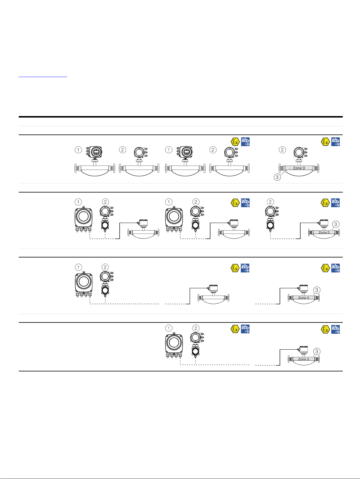
ATEX / IECEx
Standard / No explosion protection Zone 2, 21, 22 Zone 1, 21 (Zone 0)
Model number FCx4xx Y0 FCx4xx A2 FCx4xx A1
Integral mount design
• Standard
• Zone 2, 21, 22
• Zone 1, 21
• Zone 0
Model number FCT4xx Y0 FCx4xx Y0 FCT4xx A2 FCx4xx A2 FCT4xx A1 FCx4xx A1
Remote mount design
Transmitter and
flowmeter sensor
• Standard
• Zone 2, 21, 22
• Zone 1, 21
• Zone 0
Model number FCT4xx Y0 FCT4xx A2 FCx4xx A1
Remote mount design
Transmitter
• Standard
• Zone 2, 21, 22
Sensor
• Zone 1, 21
• Zone 0
Model number — FCT4xx A2 FCx4xx A1
Remote mount design
Transmitter
• Zone 2, 21, 22
Sensor
—
• Zone 1, 21
1 Single-compartment housing
2 Dual-compartment housing
3 Zone 0 within the meter tube
Page 7
CoriolisMaster FCB400, FCH400 CORIOLIS MASS FLOWMETER | OI/FCB400/FCH400-EN REV. E 7
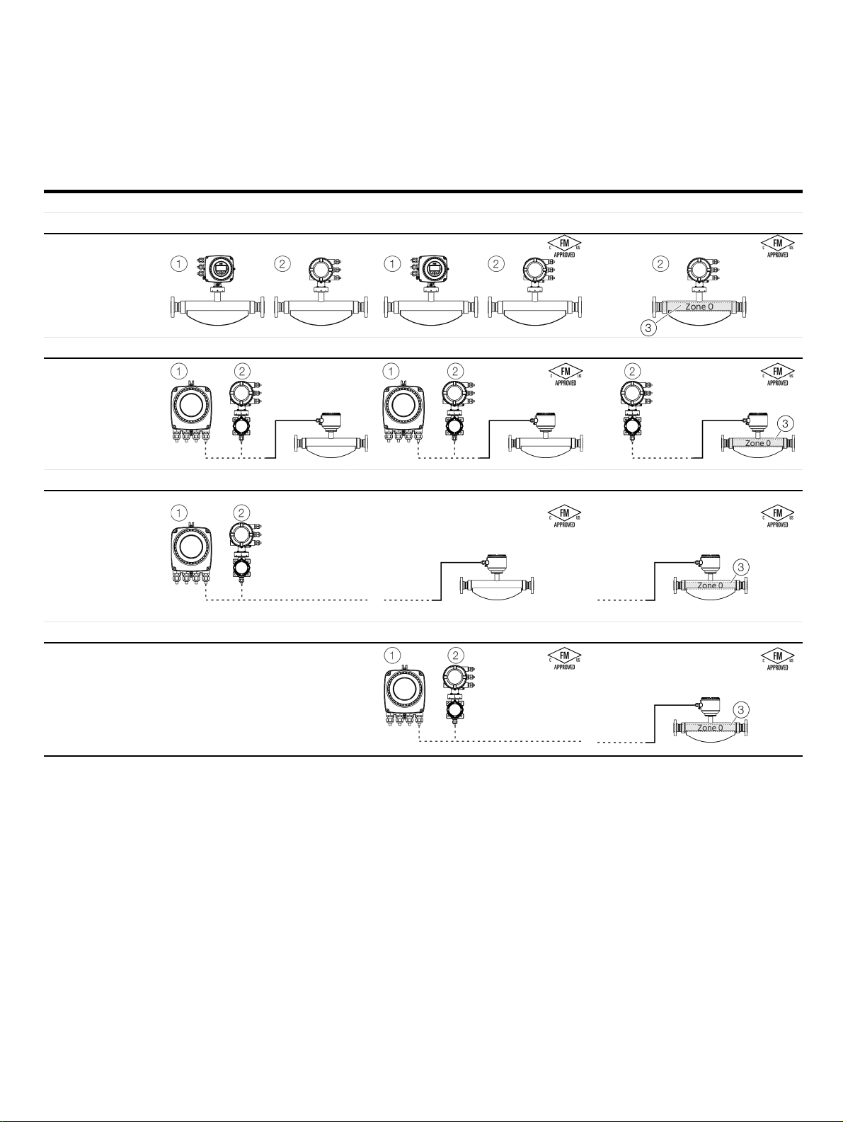
cFMus
Standard / No explosion protection Class I Div. 2 / Zone 2 Class I Div. 1 / Zone 1 (Zone 0)
Model number FCx4xx Y0 FCx4xx F2 FCx4xx F1
Integral mount design
• Standard
• Div. 2 / Zone 2
• Div. 1 / Zone 1
(Zone 0)
Model number FCT4xx Y0 FCx4xx Y0 FCT4xx F2 FCx4xx F2 FCT4xx F1 FCx4xx F1
Remote mount design
Transmitter and
flowmeter sensor
• Div. 2 / Zone 2
• Div. 1 / Zone 1
(Zone 0)
Model number FCT4xx Y0 FCT4xx F2 FCx4xx F1
Remote mount design
Transmitter
• Standard
Sensor
• Div. 2 / Zone 2
• Div. 1 / Zone 1
(Zone 0)
Model number — FCT4xx F2 FCx4xx F1
Remote mount design
Transmitter
• Div. 2 / Zone 2
Sensor
• Div. 1 / Zone 1
(Zone 0)
1 Single-compartment housing
2 Dual-compartment housing
3 Zone 0 within the meter tube
—
Page 8

8 CoriolisMaster FCB400, FCH400 CORIOLIS MASS FLOWMETER | OI/FCB400/FCH400-EN REV. E
… 2 Use in potentially explosive atmospheres
Ex marking
Description of model numbers
Each device design has a specific model number. The parts of the model number relating to explosion protection are listed in the
following table. The complete key to model numbers is described in the device data sheet.
Basic model
Explosion protection
Without
ATEX / IECEx (Zone 2 / 22)
ATEX / IECEx (Zone 1 / 21)
cFMus version, Class 1, Div. 2 (Zone 2 / 21)
cFMus version, Class 1, Div. 1 (Zone 1 / 21)
NEPSI (Zone 2 / 22)
NEPSI (Zone 1 / 21)
Design / terminal box material / cable glands
Integral mount - see transmitter housing
Remote mount / aluminum / 1 × M20 × 1.5
Remote mount / aluminum / 1 × NPT ½ in
Remote mount / stainless steel / 1 × M20 × 1.5
Remote mount / stainless steel / 1 × NPT ½ in
Nominal diameter / nominal connection diameter
Process connection
Material for wetted parts
Stainless steel
Polished stainless steel H1
Nickel alloy
Flow rate calibration
Density calibration
FCa4c d m f g h i j k l m
Y0
A2
A1
F2
F1
S2
S1
U1
A1
Y0
U2
A2
xxxxx
xx
A1
C1
x
x
Page 9

CoriolisMaster FCB400, FCH400 CORIOLIS MASS FLOWMETER | OI/FCB400/FCH400-EN REV. E 9
Basic model
Design / transmitter housing / transmitter housing material / cable gland
Integral mount / dual-compartment housing / aluminum / 3 × M20 × 1.5
Integral mount / dual-compartment housing / aluminum / 3 × NPT ½ in D2
Integral mount / dual-compartment housing / aluminum / 3 × M20 × 1.5 (Ex d / XP)
Integral mount / dual-compartment housing / aluminum / 3 × NPT ½ in (Ex d / XP) D6
Integral mount / dual-compartment housing / stainless steel / 3 × M20 × 1.5
Integral mount / dual-compartment housing / stainless steel / 3 × NPT ½ in D4
Integral mount / dual-compartment housing / stainless steel / 3 × M20 × 1.5 (Ex d /
XP)
Integral mount / dual-compartment housing / stainless steel / 3 × NPT ½ in (Ex d /
XP)
Integral mount / single-compartment housing / aluminum / 3 × M20 × 1.5 S1
Integral mount / single-compartment housing / aluminum / 3 × NPT ½ in
Remote mount / dual-compartment housing / aluminum / 3 × M20 × 1.5
Remote mount / dual-compartment housing / aluminum / 3 × NPT ½ in
Remote mount / dual-compartment housing / aluminum / 3 × M20 × 1.5 (Ex d / XP)
Remote mount / dual-compartment housing / aluminum / 3 × NPT ½ in (Ex d / XP)
Remote mount / dual-compartment housing / stainless steel / 3 × M20 × 1.5
Remote mount / dual-compartment housing / stainless steel / 3 × NPT ½ in
Remote mount / dual-compartment housing / stainless steel / 3 × M20 × 1.5 (Ex d /
XP)
Remote mount / dual-compartment housing / stainless steel / 3 × NPT ½ in (Ex d /
XP)
Remote mount / single-compartment housing, wall mounting / aluminum /
4 × M20 × 1.5
Remote mount / single-compartment housing, wall mounting / aluminum / 4 × NPT
½ in
Remote mount / not specified
Outputs
Current output 1 (active or passive), digital output 1 & 2 (passive),
HART®, PROFIBUS DP®
Current output 1 (active), digital output 1 & 2 (passive), HART®, Modbus® M1*
Current output 1 (active / passive), digital output 1 & 2 (passive), HART
Current output 1 (active / passive), digital output 1 & 2 (passive),
24 V DC transmitter loop power supply, HART®
Current output 1 (active / passive), digital output 1 & 2 (passive),
current output 2 (passive), HART®
Current output 1 (active / passive), digital output 1 & 2 (passive),
current output 2 (passive), current output 3 (passive), HART®
Current output 1 (active / passive), digital output 1 & 2 (passive),
current output 2 (passive), 24 V DC transmitter loop power supply, HART®
Without Y0
Power supply
100 to 230 V AC
11 to 30 V DC
Without
* The M1 design is identical in construction to the M5 design, as it can also be called in other locations
FCa4c d m f g h i j k l m
G3
D1
D5
D3
D7
D8
S2
R1
R2
R5
R6
R3
R4
R7
R8
W1
W2
Y0
D1
G0
G1
G2
G4
A
C
Y
Page 10

10 CoriolisMaster FCB400, FCH400 CORIOLIS MASS FLOWMETER | OI/FCB400/FCH400-EN REV. E
… 2 Use in potentially explosive atmospheres
… Ex marking
ATEX / IECEx
Note
• A specific marking applies, depending on the design.
• ABB reserves the right to modify the Ex-marking. Refer to the name plate for the exact marking.
Model number for use in Zone 2, 21 Ex marking Certificate
FCa4c – A2Y0fghijD
Integral mount design with dual-compartment
housing
FCa4c – A2efghijY
Sensor in remote mount design with dual-
compartment housing
FCT4c – A2R
Transmitter in remote mount design with dual-
compartment housing
Model number for use in Zone 1, 21 Ex marking Certificate
FCa4c – A1Y0fghijDx (x = 1 to 4)
Integral mount design with dual-compartment
housing
FCa4c – A1Y0fghijDx (x = 5 to 8)
Integral mount design with dual-compartment
housing (flameproof enclosure ‘Ex d’)
FCa4c – A1efghijY
Sensor in remote mount design with dual-
compartment housing
FCT4c – A1R (x = 1 to 4)
Transmitter in remote mount design with dual-
compartment housing
FCT4c – A1R (x = 5 to 8)
Transmitter in remote mount design with dual-
compartment housing
(flameproof enclosure ‘Ex d’)
II3G Ex ec IIC T6...T1 Gc
II2D Ex tc IIIC T80°C...Tmedium Dc
II3G Ex ec IIC T6 Gc
II2D Ex tc IIIC T80°C Dc
II 1/2 (1) G Ex db eb ia mb [ia Ga] IIC T6…T1 Gb
II 2 (1) D Ex ia tb [ia Da] IIIC T80°C Db
II 1/2 (1) G Ex db ia mb [ia Ga] IIB+H2 T6...T1 Gb
II 2 (1) D Ex ia tb [ia Da] IIIC T80°C Db
II 1/2 G Ex eb ia mb IIB+H2 T6…T1 Ga/Gb
II 2 D Ex ia tb IIIC T80°C Db
II 2 (1) G Ex db e ia mb [ia Ga] IIC T6…T1 Gb
II 2 (1) D Ex ia mb tb [ia Da] IIIC T80°C Db
II 2 (1) G Ex db ia mb [ia Ga] IIB+H2 T6…T1 Gb
II 2 (1) D Ex ia tb [ia Da] IIIC T80°C Db
ATEX:
FM15ATEX0014X, FM15ATEX0016X
IECEx:
IECEx FME 15.0005X
ATEX:
FM15ATEX0015X
IECEx:
IECEx FME 15.0005X
Page 11

CoriolisMaster FCB400, FCH400 CORIOLIS MASS FLOWMETER | OI/FCB400/FCH400-EN REV. E 11
cFMus
Note
• A specific marking applies, depending on the design.
• ABB reserves the right to modify the Ex-marking. Refer to the name plate for the exact marking.
Model number for use in Division 2 Ex marking Certificate
FCa4c – F2Y0fghijD
Integral mount design with dual-compartment housing
FCa4c – F2efghijY
Sensor in remote mount design with dual-compartment housing
Design in accordance with ANSI / ISA 12.27.01 as ‘Single Seal Device’
or as ‘Dual Seal Device’ (option TE2)
FCT4c – F2R
Transmitter in remote mount design with dual-compartment housing
Model number for use in Division 1 Ex marking Certificate
FCa4c – F1Y0fghijDx (x = 1 to 4)
Integral mount design with dual-compartment housing
FCa4c – F1Y0fghijDx (x = 5 to 8)
Integral mount design with dual-compartment housing
(Explosionproof ‘XP’).
Design in accordance with ANSI / ISA 12.27.01 as ‘Single Seal Device’
or as ‘Dual Seal Device’ (option TE2)
FCa4c – F1efghijY
Sensor in remote mount design with dual-compartment housing
Design in accordance with ANSI / ISA 12.27.01 as ‘Single Seal Device’
or as ‘Dual Seal Device’ (option TE2)
FCT4c – F1Rx (x = 1 to 4)
Transmitter in remote mount design with dual-compartment housing
FCT4c – F1Rx (x = 5 to 8)
Sensor in remote mount design with dual-compartment housing
(Explosionproof ‘XP’).
Change from one to two columns
NI: CL I,II,III Div 2, GPS ABCDEFG, T6…T1
DIP: CL II,III, Div 1, GPS EFG, T6
CL I, ZN 2, AEx ec IIC T6…T1 (USA)
ZN 21, AEx ia tb IIIC T80°C (USA)
CL I, ZN 2, Ex ec IIC T6...T1 (CAN)
ZN21,Ex ia tb IIIC T80°C (CAN)
See handbook for temperature class information
XP-IS: CL I, Div 1, GPS ABCD,T6…T1 (USA)
XP-IS: CL I, Div 1, GPS BCD,T6…T1 (CAN)
DIP: CL II,III, Div 1, GPS EFG,T6
CL I, ZN 1, AEx db ia IIB+H2 T6…T1 (USA)
ZN21, AEx ia tb IIIC T80°C (USA)
CL I, ZN 1, Ex db ia IIB+H2 T6…T1 (CAN)
ZN21, Ex ia tb IIIC T80°C (CAN)
See handbook for temperature class information and installation
drawing 3KXF000028G0009
XP-IS: CL I, Div 1, GPS BCD T6…T1 (USA)
DIP: CL II,III, Div 1, GPS EFG,T6
CL I, ZN 1, AEx db ia IIB+H2 T6…T1 (USA)
ZN 21, AEx ia tb IIIC T80°C (USA)
CL I, ZN 1, Ex db ia IIB+H2 T6…T1 (CAN)
ZN21, Ex ia tb IIIC T80°C (CAN)
See handbook for temperature class information and installation
drawing 3KXF000028G0009
XP-IS: CL I, Div 1, GPS BCD,T6…T1 (USA) XP-IS: CL I, Div 1, GPS
BCD,T6…T1 (CAN)
DIP: CL II,III, Div 1, GPS EFG, T6
CL I, ZN 1, AEx db ia IIB+H2 T6…T1 (USA)
ZN 21, AEx ia tb IIIC T80°C (USA)
CL I, ZN 1, Ex db ia IIB+H2 T6…T1 (CAN)
ZN21,Ex ia tb IIIC T80°C (CAN)
See handbook for temperature class information and installation
drawing 3KXF000028G0009
cFMus:
3050239
cFMus:
3050239
Page 12
12 CoriolisMaster FCB400, FCH400 CORIOLIS MASS FLOWMETER | OI/FCB400/FCH400-EN REV. E
… 2 Use in potentially explosive atmospheres
Temperature data
Temperature resistance for the connecting cable
Sensor in remote mount design
The temperature at the cable entries of the device depends on
the design, the measuring medium temperature T
ambient temperature T
amb.
.
medium
and the
For the electric connection of the device, use only cables with
sufficient temperature resistance in accordance with the
following table.
Devices in integral mount design with dual-compartment
housing
T
Temperature resistance
amb.
≤ 50 °C (≤ 122 °F) ≥ 105 °C (≥ 221 °F)
≤ 60 °C (≤ 140 °F) ≥ 110 °C (≥ 230 °F)
≤ 70 °C (≤ 158 °F) ≥ 120 °C (≥ 248 °F)
For sensors in remote mount design, the wires in the connection
T
Temperature resistance
amb.
≤ 50 °C (≤ 122 °F) ≥ 70 °C (≥ 158 °F)
≤ 60 °C (≤ 140 °F) ≥ 80 °C (≥ 176 °F)
≤ 70 °C (≤ 158 °F) ≥ 90 °C (≥ 194 °F)
Devices in integral mount design with single-compartment
housing
T
Temperature resistance
amb.
≤ 50 °C (≤ 122 °F) ≥ 75 °C (≥ 167 °F)
≤ 60 °C (≤ 140 °F) ≥ 85 °C (≥ 185 °F)
≤ 70 °C (≤ 158 °F) ≥ 95 °C (≥ 203 °F)
Change from two to one column
box must be additionally insulated with the enclosed silicone
hoses starting from ambient temperatures of T
amb.
≥ 60 °C
(≥ 140 °F).
Environmental and process conditions for model
FCx4xx…
Ambient temperature T
-40 to 70 °C*
Measuring medium temperature
T
medium
IP rating / NEMA rating IP 65, IP 67 /
* Optional, with order code ‘Ambient temperature range – TA9’
-20 to 70 °C
amb.
(-4 to 158 °F)
(-40 to 158 °F)*
-40 to 205 °C
(-40 to 400 °F)
NEMA 4X,Type 4X
Page 13

CoriolisMaster FCB400, FCH400 CORIOLIS MASS FLOWMETER | OI/FCB400/FCH400-EN REV. E 13
Measuring medium temperature for sensors in integral mount design with dual-compartment housing
Model FCx4xx-A1… and FCx4xx-F1… in Zone 1, Division 1
The table shows the maximum permissible measuring medium temperature as a function of ambient temperature and temperature
class.
Temperature class
Ambient temperature T
≤ 30 °C (≤ 86 °F) 205 °C (400 °F)*
≤ 40 °C (≤ 104 °F) 205 °C (400 °F)*
≤ 50 °C (≤ 122 °F) 205 °C (400 °F)*
≤ 60 °C (≤ 140 °F) 205 °C (400 °F)*
≤ 70 °C (≤ 158 °F) 205 °C (400 °F)*
* Only with the ‘Extended tower length – TE1, TE2 or TE3’ order option
T1 T2 T3 T4 T5 T6
amb.
130 °C (266 °F)
130 °C (266 °F)
130 °C (266 °F)
130 °C (266 °F)
130 °C (266 °F)
205 °C (400 °F)*
130 °C (266 °F)
205 °C (400 °F)*
130 °C (266 °F)
205 °C (400 °F)*
130 °C (266 °F)
205 °C (400 °F)*
130 °C (266 °F)
205 °C (400 °F)*
130 °C (266 °F)
195 °C (383 °F)*
130 °C (266 °F)
195 °C (383 °F)*
130 °C (266 °F)
195 °C (383 °F)*
130 °C (266 °F)
195 °C (383 °F)*
130 °C (266 °F)
195 °C (383 °F)*
130 °C (266 °F)
130 °C (266 °F) 95 °C (203 °F) 80 °C (176 °F)
130 °C (266 °F) 95 °C (203 °F) 80 °C (176 °F)
130 °C (266 °F) 95 °C (203 °F) 80 °C (176 °F)
130 °C (266 °F) 95 °C (203 °F) 80 °C (176 °F)
130 °C (266 °F) 95 °C (203 °F) 80 °C (176 °F)
Model FCx4xx-A2… and FCx4xx-F2… in Zone 2, Division 2
The table shows the maximum permissible measuring medium temperature as a function of ambient temperature and temperature
class.
Temperature class
Ambient temperature T
≤ 30 °C (≤ 86 °F) 205 °C (400 °F) 205 °C (400 °F) 195 °C (383 °F)*
≤ 40 °C (≤ 104 °F) 205 °C (400 °F) 205 °C (400 °F) 195 °C (383 °F)*
≤ 50 °C (≤ 122 °F) 205 °C (400 °F) 205 °C (400 °F) 195 °C (383 °F)*
≤ 60 °C (≤ 140 °F) 205 °C (400 °F) 205 °C (400 °F) 195 °C (383 °F)*
≤ 70 °C (≤ 158 °F) 205 °C (400 °F)*
* Only with the ‘Extended tower length – TE1, TE2 or TE3’ order option
T1 T2 T3 T4 T5 T6
amb.
130 °C (266 °F) 95 °C (203 °F) 80 °C (176 °F)*
60 °C (140 °F)
130 °C (266 °F)
205 °C (400 °F)*
130 °C (266 °F)
130 °C (266 °F)
130 °C (266 °F)
130 °C (266 °F)
130 °C (266 °F)
195 °C (383 °F)*
130 °C (266 °F)
130 °C (266 °F) 95 °C (203 °F) —
130 °C (266 °F) — —
130 °C (266 °F) — —
130 °C (266 °F) — —
Page 14

14 CoriolisMaster FCB400, FCH400 CORIOLIS MASS FLOWMETER | OI/FCB400/FCH400-EN REV. E
… 2 Use in potentially explosive atmospheres
… Temperature data
Measuring medium temperature for sensors in integral mount design with single-compartment housing
Model FCx4xx-A2… and FCx4xx-F2… in Zone 2, Division 2
The table shows the maximum permissible measuring medium temperature as a function of ambient temperature and temperature
class.
Temperature class
Ambient temperature T
≤ 30 °C (≤ 86 °F) 205 °C (400 °F) 205 °C (400 °F) 195 °C (383 °F) 130 °C (266 °F) 95 °C (203 °F) 80 °C (176 °F)
≤ 40 °C (≤ 104 °F) 205 °C (400 °F) 205 °C (400 °F) 195 °C (383 °F) 130 °C (266 °F) 95 °C (203 °F) —
≤ 50 °C (≤ 122 °F) 205 °C (400 °F) 205 °C (400 °F) 195 °C (383 °F) 130 °C (266 °F) 95 °C (203 °F) —
≤ 60 °C (≤ 140 °F) 205 °C (400 °F) 205 °C (400 °F) 195 °C (383 °F) 130 °C (266 °F) — —
≤ 70 °C (≤ 158 °F) 205 °C (400 °F) 205 °C (400 °F) 195 °C (383 °F) 130 °C (266 °F) — —
* Only with the ‘Extended tower length – TE1, TE2 or TE3’ order option
T1 T2 T3 T4 T5 T6
amb.
Page 15

CoriolisMaster FCB400, FCH400 CORIOLIS MASS FLOWMETER | OI/FCB400/FCH400-EN REV. E 15
Measuring medium temperature for sensors in remote mount design
Model FCx4xx-A1…, FCx4xx-F1… in Zone 1
The table shows the maximum permissible measuring medium temperature as a function of ambient temperature and temperature
class.
Temperature class
Ambient temperature T
≤ 30 °C (≤ 86 °F) 205 °C (400 °F) 205 °C (400 °F) 195 °C (383 °F) 130 °C (266 °F)
≤ 40 °C (≤ 104 °F) 205 °C (400 °F) 205 °C (400 °F) 195 °C (383 °F) 130 °C (266 °F)
≤ 50 °C (≤ 122 °F) 205 °C (400 °F) 205 °C (400 °F) 195 °C (383 °F) 130 °C (266 °F)
≤ 60 °C (≤ 140 °F) 205 °C (400 °F) 205 °C (400 °F) 195 °C (383 °F) 130 °C (266 °F)
≤ 70 °C (≤ 158 °F) 205 °C (400 °F) 205 °C (400 °F) 195 °C (383 °F) 130 °C (266 °F)
T1 T2 T3 T4
amb.
T5 T6
95 °C (203 °F) 80 °C (176 °F)
95 °C (203 °F) 80 °C (176 °F)
95 °C (203 °F) 80 °C (176 °F)
95 °C (203 °F) 80 °C (176 °F)
95 °C (203 °F) 80 °C (176 °F)
Model FCx4xx-A2… and FCx4xx-F2… in Zone 2, Division 2
The table shows the maximum permissible measuring medium temperature as a function of ambient temperature and temperature
class.
Temperature class
Ambient temperature T
≤ 30 °C (≤ 86 °F) 205 °C (400 °F)*
≤ 40 °C (≤ 104 °F) 205 °C (400 °F)*
≤ 50 °C (≤ 122 °F) 205 °C (400 °F)*
≤ 60 °C (≤ 140 °F) 205 °C (400 °F)*
≤ 70 °C (≤ 158 °F) 180 °C (356 °F)*
* Only with the ‘Extended tower length – TE1, TE2 or TE3’ order option
T1 T2 T3 T4 T5 T6
amb.
195 °C (383 °F)
180 °C (356 °F)
140 °C (284 °F)
120 °C (248 °F)
80 °C (176 °F)
205 °C (400 °F)*
195 °C (383 °F)
205 °C (400 °F)*
180 °C (356 °F)
205 °C (400 °F)*
140 °C (284 °F)
205 °C (400 °F)*
120 °C (248 °F)
180 °C (356 °F)*
80 °C (176 °F)
195 °C (383 °F)*
130 °C (266 °F)
195 °C (383 °F)*
130 °C (266 °F)
130 °C (266 °F)*
130 °C (266 °F)
130 °C (266 °F)*
120 °C (248 °F)
130 °C (266 °F)*
80 °C (176 °F)
130 °C (266 °F)*
95 °C (203 °F)
130 °C (266 °F)*
95 °C (203 °F)
130 °C (266 °F)*
95 °C (203 °F)
130 °C (266 °F)*
95 °C (203 °F)
130 °C (266 °F)*
80 °C (176 °F)
95 °C (203 °F)*
80 °C (176 °F)
95 °C (203 °F)*
80 °C (176 °F)
80 °C (176 °F)*
60 °C (140 °F)
80 °C (176 °F)
——
——
—
—
Page 16
16 CoriolisMaster FCB400, FCH400 CORIOLIS MASS FLOWMETER | OI/FCB400/FCH400-EN REV. E
… 2 Use in potentially explosive atmospheres
Electrical data
Overview
Standard / No explosion protection Zone 2, 21 Zone 1, 21 (Zone 0)
Division 2 and Zone 2, 21 Division 2 and Zone 1, 21
ATEX:
–
IECEx:
–
USA:
–
Canada:
–
ATEX:
II 3 G & II 2 D
IECEx:
Gc & Db
USA:
NI & DIP
AEx ec & AEx tb
Canada:
Non-Incendive & Dust Ignition Proof
Ex ec & Ex tb
ATEX:
II 1/2 (1) G & II 2 (1) D
II 1/2 G & II 2 D
II 2 (1) G & II 2 (1) D
IECEx:
(Ga) Gb & (Da) Db
Ga/Gb & Db
(Ga) Gb & (Da) Db
USA:
XP-IS & DIP
AEx db ia & AEx ia tb
Canada:
XP-IS & DIP
Ex db ia & Ex ia tb
A
B
A
B
C
G11879b
C
G11879f
A Power supply B Inputs / outputs, communication C Signal cable (remote mount design only)
• Type of protection ATEX / IECEx: Increased safety
‘Ex e’
• Type of protection USA / Canada: ‘non IS’
• Maximum 250 Vrms
• Terminals: 1+, 2-, L, N,
• Type of protection ATEX / IECEx: Either increased
safety ‘Ex e’ or intrinsically safe ‘Ex ia’
• Type of protection USA / Canada: Either ‘non IS’ or
‘intrinsically safe IS’.
• When installing in ‘Ex ia’ or ‘IS’, suitable
• Terminals: A, B, UFE, GRN
• Type of protection ATEX / IECEx: Increased safety
‘Ex e’
• Type of protection USA / Canada: ‘non IS’
intrinsically safe isolation amplifiers must be used
for the connection.
• Terminals: 31, 32, Uco, V1, V2, V3, V4, 41, 42, 51, 52
Note
When installing in ‘Ex ia’ or ‘IS’ type of protection, the type of protection is determined by the type of electrical connection. The
information in Changing the type of protection on page 24 must be observed when changing the type of protection!
Page 17

CoriolisMaster FCB400, FCH400 CORIOLIS MASS FLOWMETER | OI/FCB400/FCH400-EN REV. E 17
Zone 2, 21 and Division 2 – Model: FCx4xx-A2, FCx4xx-F2
Outputs on basic device Operating values (general) Type of protection – ‘nA’ / ‘NI’
U
Current / HART output 31 / UCO, active
Terminals 31 / UCO
Current / HART output 31 / 32, passive
Terminals 31 / 32
Digital output 41 / 42, active*
Terminals 41 / 42 and V1 / V2*
Digital output 41 / 42, active**
Terminals 41 / 42 and UCO / 32**
Digital output 41 / 42, passive
Terminals 41 / 42
Digital output 51 / 52, active*
Terminals 51 / 52 and V1 / V2*
Digital output 51 / 52, passive
Terminals 51 / 52
All outputs are electrically isolated from each other and from the power supply.
Digital outputs 41 / 42 and 51 / 52 are not electrically isolated from each other. Terminals 42 / 52 have the same potential.
* Only in conjunction with additional ‘24 V DC loop power supply (blue)’ plug-in card in slot OC1.
** Only in conjunction with current output U
page 50.
/ 32 in ‘Powermode’, see Current output Uco / 32 as loop power supply for digital output 41 / 42 or 51 / 52 on
CO
N
30 V 30 mA 30 V
30 V 30 mA 30 V
30 V 30 mA 30 V
30 V 30 mA 30 V
30 V 25 mA 30 V
30 V 30 mA 30 V
30 V 30 mA 30 V
Inputs and outputs with optional plug-in cards Operating values (general) Type of protection – ‘nA’ / ‘NI’
U
N
Current output V3 / V4, active*
Terminals V3 / V4 and V1 / V2*
Current output V1 / V2, passive**
Current output V3 / V4, passive**
Terminals V1 / V2** or V3 / V4**
Digital output V3 / V4, active*
Terminals V3 / V4 and V1 / V2*
Digital output V1 / V2, passive**
Digital output V3 / V4, passive**
Terminals V1 / V2** or V3 / V4**
Digital input V3 / V4, active*
Terminals V3 / V4 and V1 / V2
Digital input V1 / V2, passive*
Digital input V3 / V4, passive*
Terminals V1 / V2** or V3 / V4**
Modbus® / PROFIBUS DP®
Terminals V1 / V2
* Only in conjunction with additional ‘24 V DC loop power supply (blue)’ plug-in card in slot OC1.
** The terminal assignment depends on the model number or the slot assignments. For connection examples, see Connection examples on page 53.
30 V 30 mA 30 V 30 mA
30 V 30 mA 30 V 30 mA
30 V 25 mA 30 V 25 mA
30 V 30 mA 30 V 30 mA
30 V 3.45 mA 30 V 3.45 mA
30 V 3.45 mA 30 V 3.45 mA
30 V 30 mA 30 V 30 mA
I
N
I
N
U
N
30 mA
30 mA
30 mA
30 mA
25 mA
30 mA
30 mA
U
N
I
N
I
N
Page 18

18 CoriolisMaster FCB400, FCH400 CORIOLIS MASS FLOWMETER | OI/FCB400/FCH400-EN REV. E
—30
—30
—30
—
—
—
—
—
—
… 2 Use in potentially explosive atmospheres
… Electrical data
Zone 1 ,21 und Division 1 – Model: FCx4xx-A1, FCx4xx-F1
Type of protection ‘e’ / ‘XP’ ‘ia’ / ‘IS’
Outputs on basic device U
Current / HART output 31 / UCO, active
M
[V]
30 0.2
[A]
I
M
U
[V]
U
I
I
P
P
C
C
C
C
O
I
O
I
O
I
O
I
OPA
[V]
[mA]
[mA]
[mW]
[mW]
[nF]
[nF]
[nF]
IPA
[nF]
L
[mH]
O
[mH]
30 30 115 115 815 815 10 10 5 5 0.08 0.08
Terminals 31 / UCO
Current / HART output 31 / 32, passive
30 0.2
— 115 — 815 — 27 — 5 0.08 0.08
Terminals 31 / 32
Digital output 41 / 42, active*
30 0.1
27.8 30 119 30 826 225 20 20 29 29 0.22 0.22
Terminals 41 / 42 and V1 / V2*
Digital output 41 / 42, active**
30 0.1
30 30 115 115 826 225 16 16 10 10 0.08 0.08
Terminals 41 / 42 and UCO / 32**
Digital output 41 / 42, passive
30 0.1
— 30 — 225 — 27 — 5 — 0.08
Terminals 41 / 42
Digital output 51 / 52, active*
30 0.1
27.8 30 119 30 826 225 20 20 29 29 0.22 0.22
Terminals 51 / 52 and V1 / V2*
Digital output 51 / 52, passive
30 0.1
— 30 — 225 — 27 — 5 — 0.08
Terminals 51 / 52
All outputs are electrically isolated from each other and from the power supply.
Digital outputs 41 / 42 and 51 / 52 are not electrically isolated from each other. Terminals 42 / 52 have the same potential.
* Only in conjunction with additional ‘24 V DC loop power supply (blue)’ plug-in card in slot OC1.
** Only in conjunction with current output U
/ 32 in ‘power mode’, see Current output Uco / 32 as loop power supply for digital output 41 / 42 or 51 / 52 on
CO
page 50.
Type of protection ‘e’ / ‘XP’ ‘ia’ / ‘IS’
Inputs and outputs with optional plug-in cards U
Current output V3 / V4, active*
I
M
M
[V]
[A]
30 0.1 27.8 30 119 30 826 225 29 29 117 117 0.4 0.4
Terminals V3 / V4 and V1 / V2*
Current output V1 / V2, passive**
30 0.1 — 30
Current output V3 / V4, passive**
Terminals V1 / V2** or V3 / V4**
Digital output V3 / V4, active*
30 0.1 27.8 30 119 68 826 225 17 17 31 31 0.4 0.4
Terminals V3 / V4 and V1 / V2*
Digital output V1 / V2, passive**
30 0.1 — 30
Digital output V3 / V4, passive**
Terminals V1 / V2** or V3 / V4**
Digital input V3 / V4, active*
30 0.1 27.8 30 119 3.45 826 25.8 17 17 31 31 0.4 0.4
Terminals V3 / V4 and V1 / V2
Digital input V1 / V2, passive*
30 0.1 — 30
Digital input V3 / V4, passive*
Terminals V1 / V2** or V3 / V4**
Modbus® / PROFIBUS DP®
30 0.1 4.2 4.2 150 150 150 150 1.5 1.5 6 6 0.14 0.14
Terminals V1 / V2
* Only in conjunction with additional ‘24 V DC loop power supply (blue)’ plug-in card in slot OC1.
** The terminal assignment depends on the model number or the slot assignments. For connection examples, see Connection examples on page 53.
Change from one to two columns
U
[V]
U
I
I
O
I
O
[V]
[mA]
[mA]
I
P
[mW]
O
[mW]
68 — 510 — 45 — 59
30 — 225 — 13 — 16
3.45 — 25.8 — 13 — 16
C
C
[nF]
C
C
I
OPA
[nF]
IPA
[nF]
L
[mH]
O
[mH]
P
I
O
[nF]
0.27
0.27
0.27
L
I
L
I
Page 19

CoriolisMaster FCB400, FCH400 CORIOLIS MASS FLOWMETER | OI/FCB400/FCH400-EN REV. E 19
… 2 Use in potentially explosive atmospheres
… Electrical data
Special connection conditions
Note
The AS plug-in card (24 V DC loop power supply) may only be
used to power the internal inputs and outputs on the device.
It must not be used to power external circuits!
Note
If the protective earth (PE) is connected in the flowmeter's
terminal box, you must ensure that no dangerous potential
difference can arise between the protective earth (PE) and the
potential equalization (PA) in areas with explosion risk.
Note
• For devices with a power supply of 11 to 30 V DC, on-site
external overvoltage protection must be provided.
• You must make sure that the overvoltage is limited to
140 % (= 42 V DC) of the maximum operating voltage.
The output circuits are designed so that they can be connected
to both intrinsically-safe and non-intrinsically-safe circuits.
• Combining intrinsically safe and non-intrinsically safe circuits
is not permitted.
• On intrinsically safe circuits, potential equalization should be
established along the entire length of the cable used for the
signal outputs.
• The rated voltage of the non-intrinsically safe circuits is
= 30 V.
U
M
• Intrinsic safety is preserved If the rated voltage U
= 30 V is
M
not up-scaled when connections are established to nonintrinsically safe external circuits.
• The information in Changing the type of protection on
page 24 must be observed when changing the type of
protection.
Devices connected to the relevant equipment must not be
operated at over 250 V
AC or 250 V DC to ground.
rms
Installation in accordance with ATEX or IECEx must comply with
the applicable national and international standards and
directives.
Installation in the USA or Canada must comply with ANSI / ISA
RP 12.6, ‘Installation of intrinsically safe systems for hazardous
(classified) locations’, the ‘National Electrical Code (ANSI / NFPA
70), sections 504, 505’ and the ‘Canadian electrical code (C22.1-
02)’.
Apparatus connected to the flowmeter must have appropriate
explosion protection approval in accordance with the Entity
concept.
The apparatus must have intrinsically safe circuits.
The apparatus must be installed and connected in accordance
with the relevant manufacturer documentation.
The electrical specifications in Electrical data on page 16 must
be observed.
Page 20

20 CoriolisMaster FCB400, FCH400 CORIOLIS MASS FLOWMETER | OI/FCB400/FCH400-EN REV. E
… 2 Use in potentially explosive atmospheres
Installation instructions
ATEX / IECEx
The installation, commissioning, maintenance and repair of
devices in potentially explosive atmospheres must only be
carried out by appropriately trained personnel. Works may be
carried out only by persons, whose training has included
instructions on different types of protection and installation
techniques, concerned rules and regulations as well as general
principles of zoning.
The person must possess the appropriate competences for the
type of work to be conducted.
The safety instructions for electrical apparatus in potentially
explosive areas must be in accordance with Directive
2014/34/EU (ATEX) and IEC 60079-14 (Installation of electrical
equipment in potentially explosive areas).
Comply with the applicable regulations for the protection of
employees to ensure safe operation.
cFMus
The installation, commissioning, maintenance and repair of
devices in areas with explosion hazard must only be carried out
by appropriately trained personnel.
The operator must strictly observe the applicable national
regulations with regard to installation, function tests, repairs,
and maintenance of electrical devices. (e. g. NEC, CEC).
Use in areas exposed to combustible dust
When using the device in areas exposed to combustible dusts
(dust ignition), the following points must be observed:
• The maximum surface temperature of the device may not
up-scale 85 °C (185 °F).
• The process temperature of the attached piping may up-
scale 85 °C (185 °F).
• Approved dust-proof cable glands must be used when
operating in Zone 21, 22 or in Class II, Class III.
Opening and closing the housing
DANGER
Danger of explosion if the device is operated with the
transmitter housing or terminal box open!
While using the device in potentially explosive atmospheres
before opening the transmitter housing or the terminal box,
note the following points:
• A valid fire permit must be present.
• Make sure that no flammable or hazardous atmospheres
are present.
WARNING
Risk of injury due to live parts!
When the housing is open, contact protection is not provided
and EMC protection is limited.
• Before opening the housing, switch off the power supply.
See also Opening and closing the housing on page 38.
Only original spare parts must be used to seal the housing.
Note
Spare parts can be ordered from ABB Service.
www.abb.com/contacts
Page 21
CoriolisMaster FCB400, FCH400 CORIOLIS MASS FLOWMETER | OI/FCB400/FCH400-EN REV. E 21
Cable entries in accordance with ATEX / IECEx
The devices are supplied with cable glands installed (certified in
accordance with ATEX or IECEx).
• The use of standard cable glands and closures is prohibited.
• The black plugs in the cable glands are intended to provide
protection during transport.
• The outside diameter of the connection cable must measure
between 6 mm (0.24 in) and 12 mm (0.47 in) to guarantee the
required tightness.
• Black cable glands are installed by default when the device is
supplied. If signal outputs are connected to intrinsically safe
circuits, replace the black cap on the corresponding cable
gland with the blue one supplied.
• Any unused cable entries must be sealed before
commissioning in accordance with the applicable standards.
Note
Low-temperature version devices (optional, up to −40 °C (−40 °F)
ambient temperature) are supplied with metal cable glands due
to the required temperature resistance.
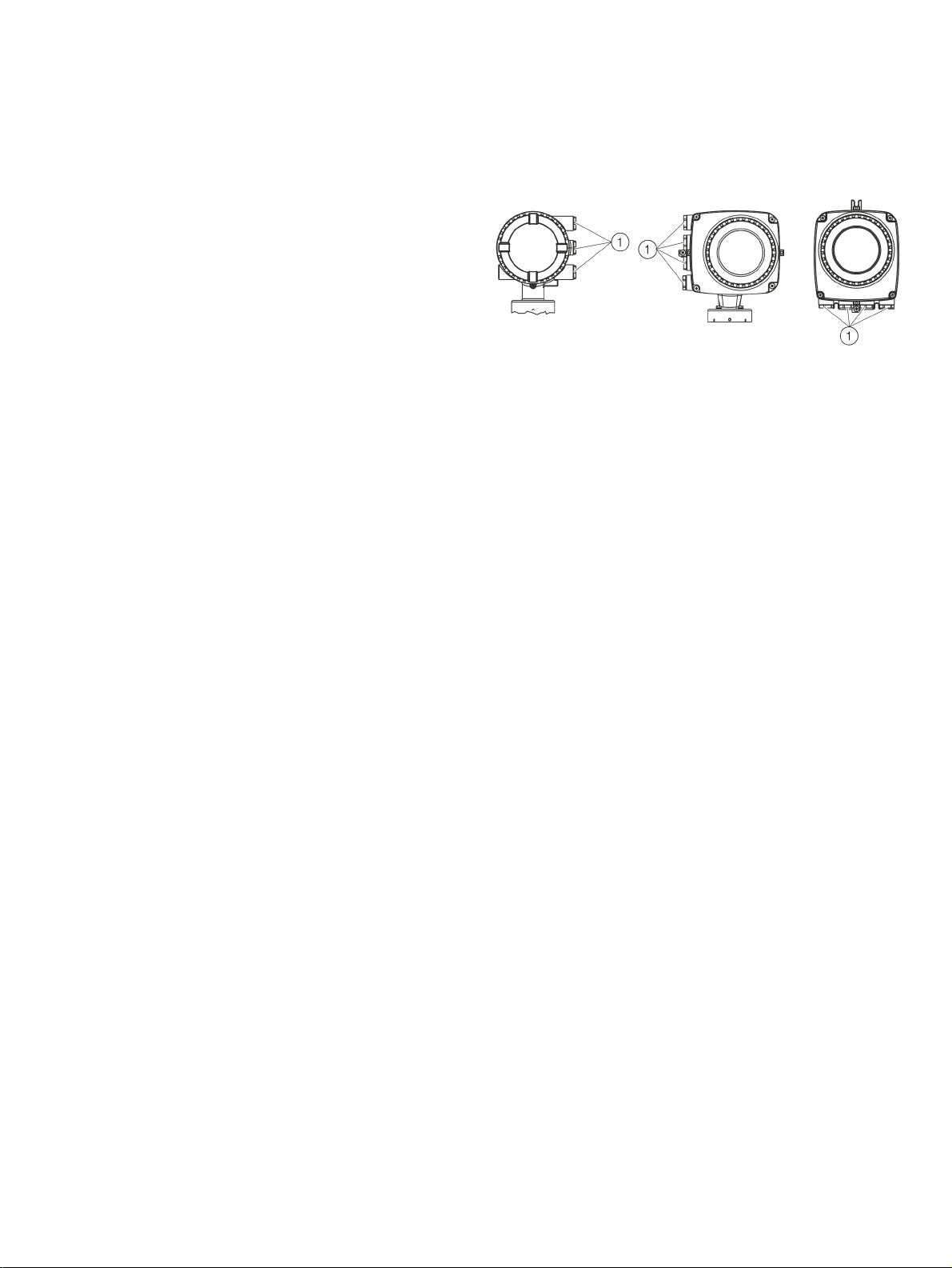
Cable entries in accordance with cFMus
1 Transport protection plugs
Figure 1: Cable entry
The devices are delivered with ½ in NPT threads with transport
protection plugs.
• Unused cable entries must be sealed off prior to
commissioning using either approved pipe fittings or cable
glands in accordance with national regulations (NEC, CEC).
• Make sure that the pipe fittings, cable glands and, if
applicable, sealing plugs are installed properly and are leaktight.
• If the device is to be operated in areas with combustible
dusts, a threaded pipe connection or cable gland with
suitable approval must be used.
• The use of standard cable glands and closures is prohibited.
Note
Devices which are certified for use in North America are supplied
with a ½ in. NPT thread only and without cable glands.
Page 22

22 CoriolisMaster FCB400, FCH400 CORIOLIS MASS FLOWMETER | OI/FCB400/FCH400-EN REV. E
… 2 Use in potentially explosive atmospheres
… Installation instructions
Electrical connections
Note
The temperature at the cable entries of the device depends on
the design, the measuring medium temperature T
ambient temperature T
amb.
.
medium
and the
For the electric connection of the device, use only cables with
sufficient temperature resistance in accordance with the tables
at Temperature resistance for the connecting cable on page 12.
Grounding
The sensor must be grounded in accordance with the applicable
international standards.
Perform grounding of the device in accordance with Pin
assignment on page 48.
In accordance with NEC standards, an internal ground
connection is present in the device between the sensor and the
transmitter.
Perform grounding of the device in accordance with Pin
assignment on page 48.
Process sealing
In accordance with ‘North American Requirements for Process
Sealing between Electrical Systems and Flammable or
Combustible Process Fluids’.
Note
The device is suitable for use in Canada.
• For use in Class II, Groups E, F and G, a maximum surface
temperature of 165 °C (329 °F) may not be up-scaled.
• All cable (conduits) should be sealed from the device within a
distance of 18 in (457 mm).
ABB flowmeters are designed for the worldwide industrial
market and are suitable for functions such as the measurement
of flammable and combustible liquids and can be installed in
process pipes.
Connecting devices with cable (conduits) to the electric
installation makes it possible for measuring media to reach the
electric system.
To prevent measuring media from seeping into the electric
installation, the devices are equipped with process gaskets
which meet requirements in accordance with ANSI / ISA 12.27.01.
Coriolis mass flowmeters are designed as ‘Single Seal Devices’.
With the TE2 order option, ‘Extended tower length - insulation
capacity with dual gasket’, the devices can be used as a ‘Dual
Seal Devices’.
In accordance with the requirements of standard
ANSI / ISA 12.27.01, the existing operating limits of temperature,
pressure and pressure bearing parts must be reduced to the
following limit values:
Limit values
Flange or pipe material No limitations
Nominal sizes DN 15 to DN 150
(½ to 6 in)
Operating temperature -50 °C to 205 °C
(-58 °F to 400 °F)
Process pressure PN 100 / Class 600
Page 23
CoriolisMaster FCB400, FCH400 CORIOLIS MASS FLOWMETER | OI/FCB400/FCH400-EN REV. E 23
Operating instructions
Protection against electrostatic discharges
DANGER
Risk of explosion!
The painted surface of the device can store electrostatic
charges.
As a result, the housing can form an ignition source due to
electrostatic discharges in the following conditions:
• The device is operated in environments with a relative
humidity of ≤ 30 %.
• The painted surface of the device is thereby relatively free
from impurities such as dirt, dust or oil.
• Instructions on avoiding ignition in potentially explosive
environments due to electrostatic discharges in
accordance with PD CLC/TR 60079-32-1 and IEC TS 6007932-1 must be complied with!
Instructions on cleaning
The painted surface of the device must be cleaned only using a
moist cloth.
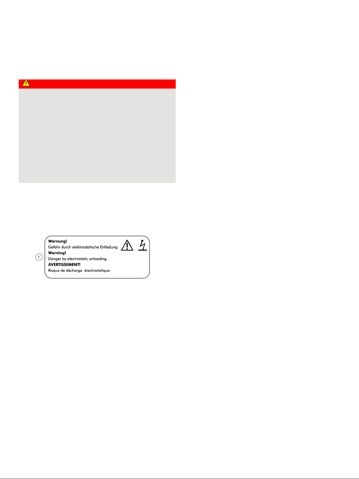
Devices which are approved for use in potentially explosive
atmospheres have an additional warning plate.
1 WARNING! – Danger due to electrostatic discharge.
Figure 2: Additional warning plate
Repair
Devices of type of protection ‘d’ are equipped with flameproof
joints in the housing. Contact ABB before commencing repair
work.
Change from two to one column
Page 24

24 CoriolisMaster FCB400, FCH400 CORIOLIS MASS FLOWMETER | OI/FCB400/FCH400-EN REV. E
… 2 Use in potentially explosive atmospheres
… Operating instructions
Changing the type of protection
If you are installing in Zone 1 / Div. 1, the current outputs and digital outputs of models FCB430/450 and FCH430/450 can be
operated with different types of protection:
• Current output and digital output in the ‘intrinsically safe ia / IS’ design
• Current output and digital output in non-intrinsically safe design
If a device that is already operational is operated with a different type of protection, the following measures must be
implemented/insulation checks performed in accordance with applicable standards.
Original installation New installation Necessary test steps
Zone 1 / Div. 1:
Current outputs and digital outputs in
non-intrinsically safe design
Zone 1 / Div. 1:
Current outputs and digital outputs in
intrinsically safe ia(ib) / IS design
Change from one to two columns
Zone 1 / Div. 1:
Current outputs and digital outputs in
intrinsically safe ia / IS design
Zone 1 / Div. 1:
Current outputs and digital outputs in
non-intrinsically safe design
• 500 V AC/1min or 500 × 1.414 = 710 V DC/1min
Test between terminals A / B, U
V1 / V2 and V3 / V4, and terminals A, B, U
, /GND, UCO / 32, 31 / 32, 41 / 42, 51 / 52,
FE
, GND, UCO, 31, 32, 41, 42, 51, 52,
FE
V1, V2, V3, V4 and the housing.
When this test is performed, no voltage flashover is permitted in or on the
device.
• Optical evaluation particularly of the electronic circuit boards, no visible
damage or evidence of explosion.
• Visual inspection, no damage visible on the threads (cover, ½ in NPT cable
glands).
Page 25
CoriolisMaster FCB400, FCH400 CORIOLIS MASS FLOWMETER | OI/FCB400/FCH400-EN REV. E 25
3 Design and function
General
The ABB CoriolisMaster operates according to the Coriolis
principle.
The construction features conventional parallel meter tubes and
is characterized in particular by its space-saving, sturdy design,
wide range of nominal diameters and minimal pressure loss.
Measuring principle
If mass flows through a vibrating pipe, Coriolis forces are
generated which bend or twist the pipe. These very small
measurement pipe deformations are picked up by optimally
mounted sensors and electronically evaluated. Because the
measured phase shift of the sensor signals is proportional to the
mass flow, the mass conveyed by the measuring device can be
recorded directly using the Coriolis mass flowmeter. The
metering principle is independent of the density, temperature,
viscosity, pressure and conductivity of the fluid.
The meter tubes always vibrate at resonance. This arising
resonant frequency is a function of the meter tube geometry, the
characteristics of the materials and the mass of the medium in
the resonating meter tube. It provides an accurate measure of
the density of the measuring medium.
An integrated temperature sensor records the measuring
medium temperature and is utilized for corrections to
temperature-dependent device parameters. In summary, it is
possible to simultaneously measure mass flow, density and
temperature with the Coriolis Mass Flowmeter. Other
measurement values can be derived from these values, e.g.
volume flow rate or concentration.
Change from two to one column
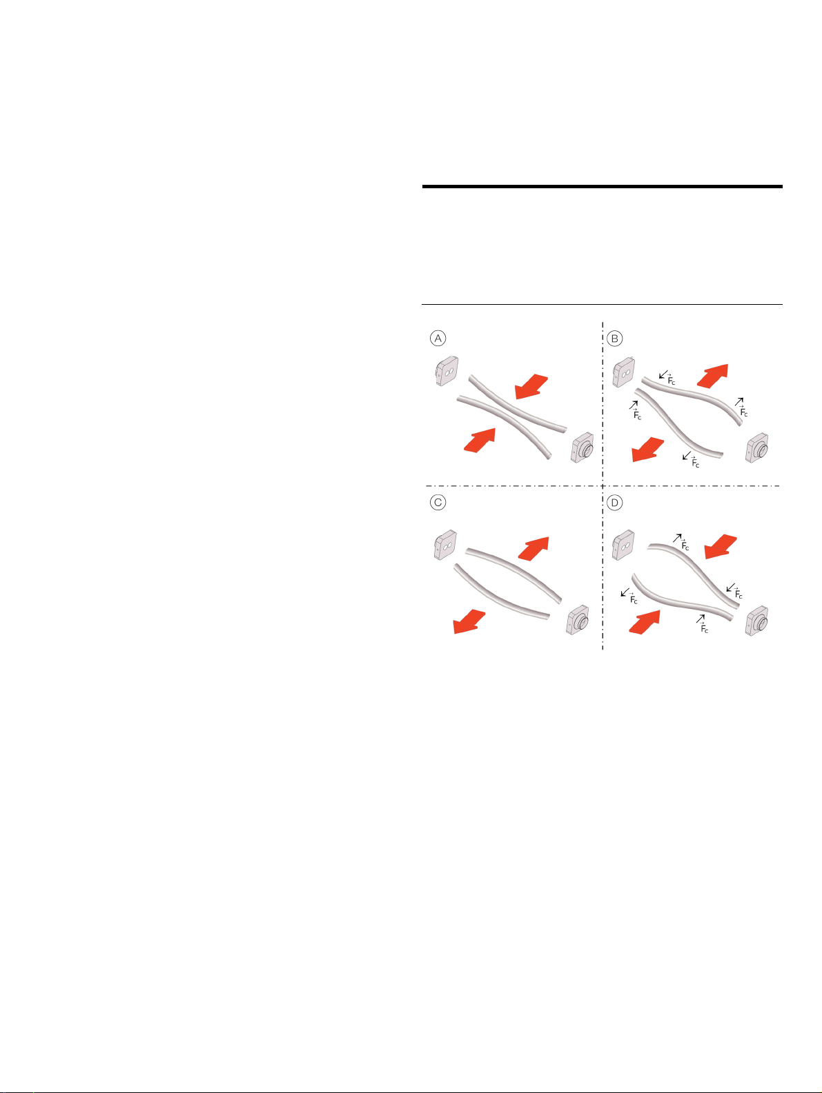
Function for calculating Coriolis force
2
cF
Coriolis force
Angular velocity
v
Velocity of the mass
m Mass
A Movement of the pipes inward, no flow
B Direction of the Coriolis force with flow and movement of the pipes
outward
C Movement of the pipes outward, no flow
D Direction of the Coriolis force with flow and movement of the pipes
inward
Figure 3: Simplified representation of Coriolis forces
vmcF
Page 26
26 CoriolisMaster FCB400, FCH400 CORIOLIS MASS FLOWMETER | OI/FCB400/FCH400-EN REV. E
… 3 Design and function
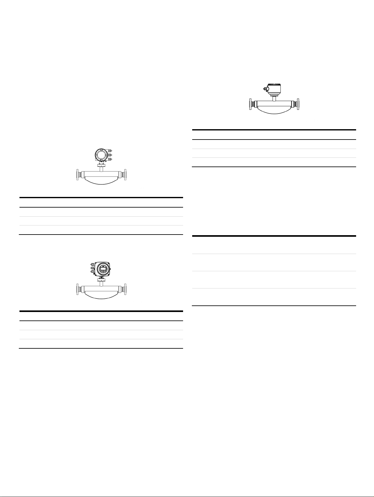
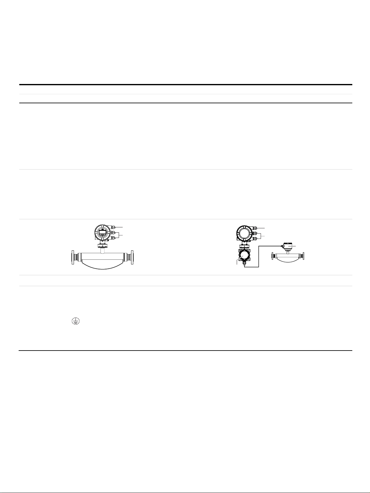
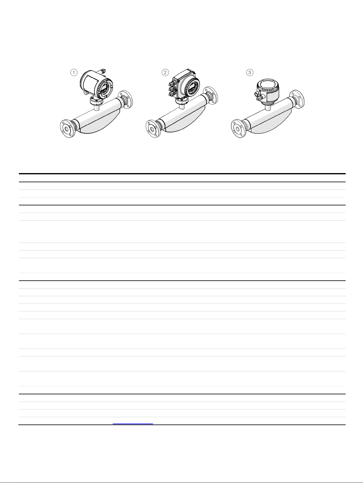
Device designs
1 Sensor (integral mount design, dual-compartment housing)
2 Sensor (integral mount design, single-compartment housing)
Figure 4: Designs
3 Sensor (remote mount design)
Sensor
Model FCB400 standard design FCH400 hygienic design
Housing Integral mount design, remote mount design
Measuring accuracy for liquids FCB430 FCB450 FCH430 FCH450
Mass flow* 0.4 %, 0.25 % and 0.2 % 0.1 % and 0.15 % 0.4 %, 0.25 % and 0.2 % 0.1 % and 0.15 %
Volume flow* 0.4 %, 0.25 % and 0.2 % 0.15 % and 0.11 % 0.4 %, 0.25 % and 0.2 % 0.15 % and 0.11 %
Density 0.01 kg/l
Temperature 1 K 0.5 K 1 K 0.5 K
Measuring accuracy for gases* 1 % 0.5 % 1 % 0.5 %
Permissible measuring medium
temperature T
medium
−50 to 160 °C
(−58 to 320 °F)
Process connection
Flange DIN 2501 / EN 1092-1 DN 10 to 200; PN 40 to PN 160 —
Flange ASME B16.5 DN ½ to 8 in; CL150 to CL1500 —
JIS flange DN 10 to 200; JIS 10K to 20K —
Pipe fitting DIN 11851 DN 10 to 100 (⅜ to 4 in) DN 15 to 100 (½ to 4 in)
Pipe fitting SMS 1145 DN 25 to 80 (1 to 3 in) —
Tri-clamp DIN 32676 (ISO 2852)
Tri-clamp BPE
Female thread DIN ISO 228 and
DN 15 to 100 (¼ to 4 in)
DN ⅜ to 4 in
DN 15; PN 100 —
ASME B 1.20.1
Other connections On request On request
Wetted material Stainless steel 1.4435 or 1.4404 (AISI 316L), nickel-alloy
C4 / C22 (optional)
IP rating • Integral mount design: IP 65 / IP 67, NEMA 4X
• Remote mount design: IP 65 / IP 67 / IP 68 (sensor only, immersion depth: 5 m), NEMA 4X
Approvals
• Explosion protection ATEX / IECEx / cFMus ATEX / IECEx / cFMus
• Hygiene approvals — EHEDG, FDA compliant
• Legal metrology Type-tested for legal metrology in accordance with MID / OIML R117 or API / AGA
• Further approvals At www.abb.com/flow or upon request.
* Indication of accuracy in % of the measured value
• 0.002 kg/l
• 0.001 kg/l (optional)
• 0.0005 kg/l
−50 to 205 °C
(−58 to 400 °F)
0.01 kg/l
−50 to 160 °C
(−58 to 320 °F)
• 0.002 kg/l
• 0.001 kg/l (optional)
• 0.0005 kg/l
−50 to 205 °C
(−58 to 400 °F)
DN 20 to 100 (¼ to 4 in)
DN ⅜ to 4 in
Stainless steel, polished 1.4404 (AISI 316L) or 1.4435 (AISI
316L)
Page 27
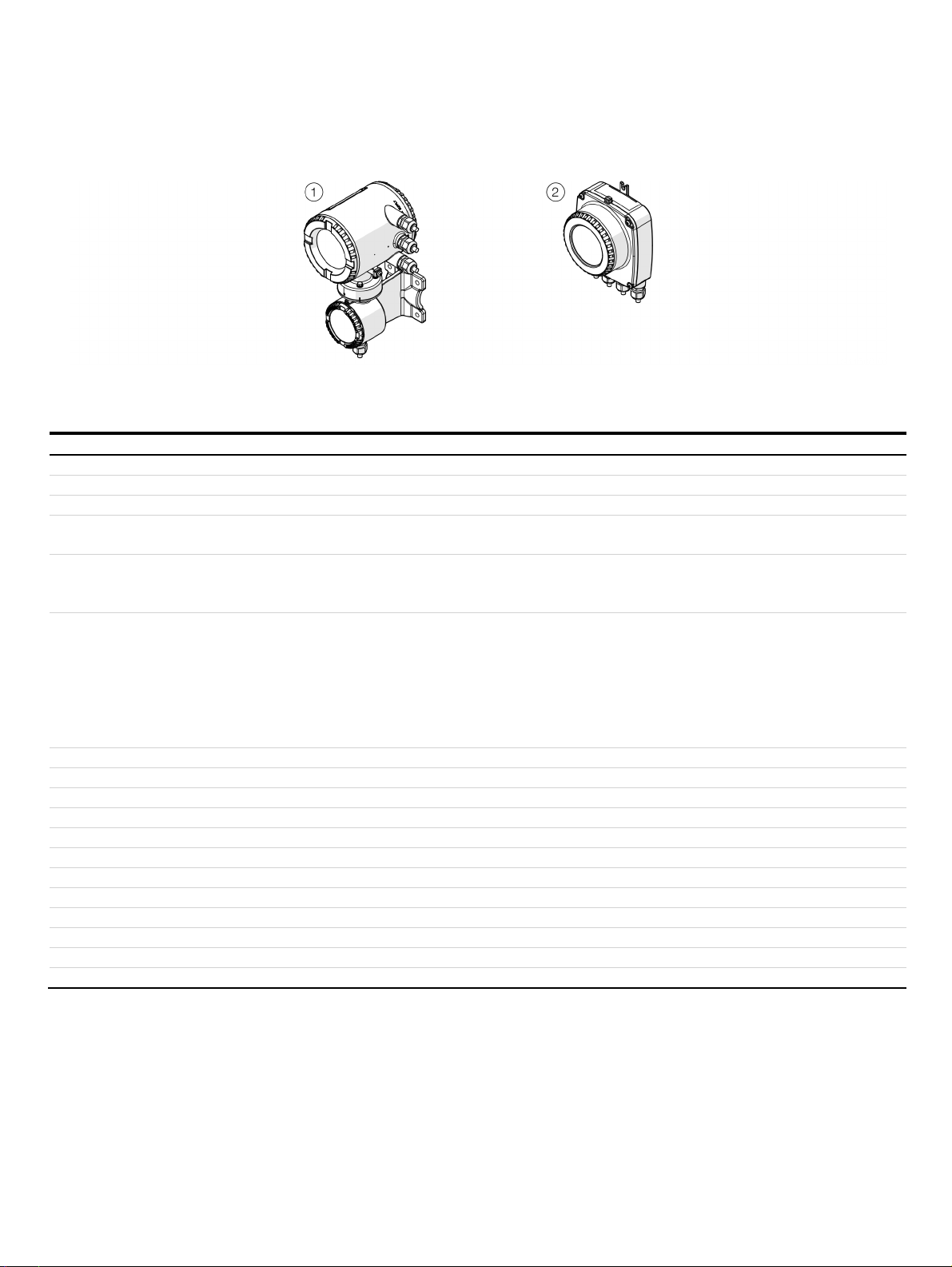
CoriolisMaster FCB400, FCH400 CORIOLIS MASS FLOWMETER | OI/FCB400/FCH400-EN REV. E 27
1 Dual-compartment housing
Figure 5: Transmitter with remote mount design
2 Single-compartment housing
Transmitter
Housing Integral mount design (see Figure 4, pos. 1 and 2), remote mount design.
IP rating IP 65 / IP 67, NEMA 4X
Cable length Maximum 200 m (656 ft), with remote mount design only
Power supply 100 to 240 V AC, 50 / 60 Hz
11 to 30 V DC, nominal voltage: 24 V DC
Outputs in basic version Current output: 4 to 20 mA active or passive
Digital output 1: passive, configurable as pulse, frequency or switch output
Digital output 2: passive, configurable as pulse or switch output
Additional optional outputs The transmitter has two slots in which plug-in cards can be inserted to provide additional inputs and
outputs. The following plug-in cards are available:
• Current output (maximum two plug-in cards simultaneously)
• Digital output (maximum one plug-in card)
• Digital input (maximum one plug-in card)
• Modbus or PROFIBUS DP interface (maximum of one plug-in card)
• 24 V DC loop power supply for active outputs (maximum one plug-in card)
External output zero return Yes
External totalizer reset Yes
Forward / reverse flow metering Yes
Counter Yes
Communication HART® protocol 7.1, Modbus® or Profibus DP® (using a plug-in card)
Empty pipe detection Yes, via configurable density alarm
Self-monitoring and diagnosis Yes
Local indicator Yes
Field optimization for flow and density Yes
Concentration measurement ‘DensiMass’ Yes, optional on models FCB450 and FCH450
‘FillMass’ filling function Yes, optional on models FCB450 and FCH450
‘VeriMass’ function Yes, optional
Change from one to two columns
Page 28
28 CoriolisMaster FCB400, FCH400 CORIOLIS MASS FLOWMETER | OI/FCB400/FCH400-EN REV. E
4 Product identification
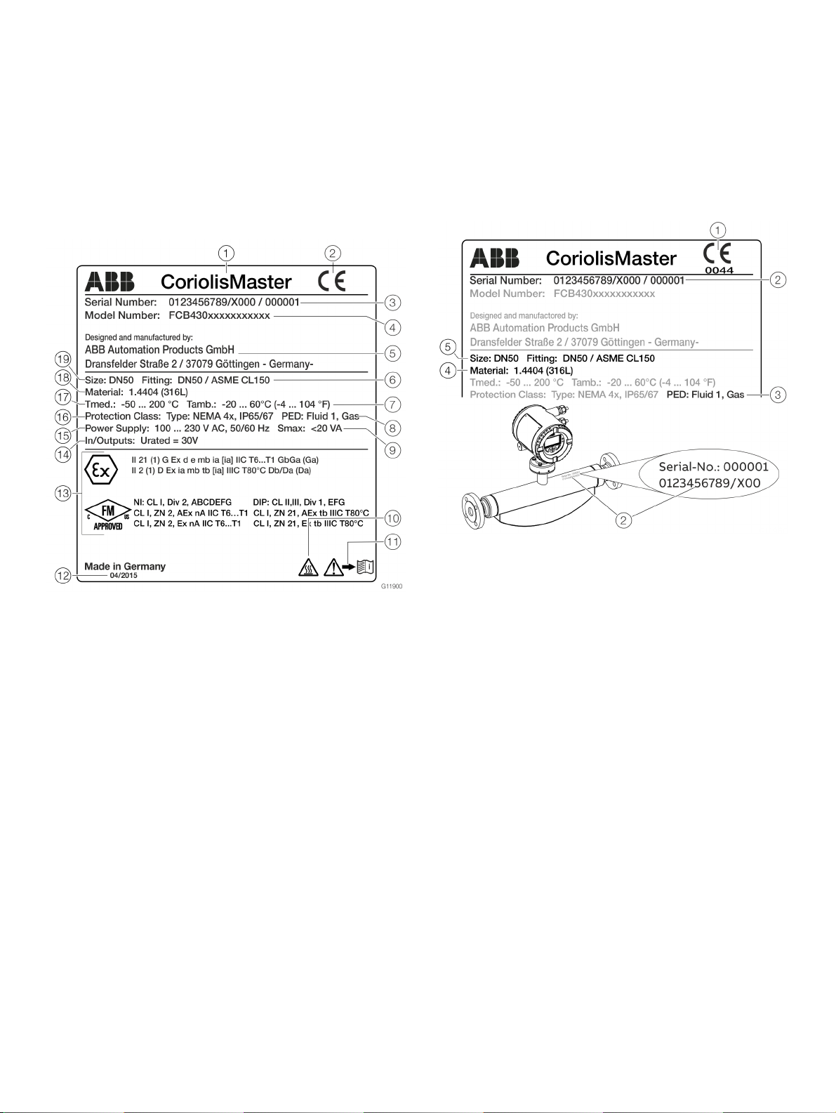
Name plate
Note
The name plates displayed are examples. The device
identification plates affixed to the device can differ from this
representation.
The marking is provided on the name plate and on the sensor
itself in accordance with the Pressure Equipment Directive
(PED).
1 Type designation
2 CE mark
3 Serial number
4 Order code
5 Manufacturer
6 Process connection / pressure
rating
7 Ambient temperature range
8 PED marking
9 Maximum power consumption
j ‘Hot surface’ symbol
k ‘Observe operating instruction’
symbol
Figure 6: Name plate (example)
l Year of manufacture
(month / year)
m Ex marking, such as ATEX / IECEx
or FM / CSA
n Maximum voltage at inputs and
outputs
o Power supply
p IP rating
q Measuring medium temperature
range
r Meter tube material
s Nominal diameter
1 CE mark with notified body
2 Serial number of the sensor
3 Fluid group or reason for
exception
Figure 7: PED marking (example)
4 Material of the pressure-bearing
parts (wetted parts)
5 Nominal diameter / Nominal
pressure rating
The marking is dependent on the nominal diameter (> DN 25 or
≤ DN 25) of the sensor (also refer to Pressure Equipment
Directive 2014/68/EU).
Pressure equipment within the scope of the Pressure
Equipment Directive
The number of the notified body is specified underneath the CE
mark to confirm that the device meets the requirements of the
Pressure Equipment Directive.
The respective fluid group in accordance with the Pressure
Equipment Directive is indicated under PED.
Example: Fluid Group 1 = hazardous fluids, gaseous.
Pressure equipment beyond the scope of the Pressure
Equipment Directive
In PED the exception to Article 4 (3) of the Pressure Equipment
Directive is specified.
The pressure equipment is classified in the SEP (= Sound
Engineering Practice) ‘Good Engineering Practice’ category.
Page 29
CoriolisMaster FCB400, FCH400 CORIOLIS MASS FLOWMETER | OI/FCB400/FCH400-EN REV. E 29
5 Transport and storage
Observe the following instructions:
• Do not expose the device to humidity during transport.
Pack the device accordingly.
• Pack the device so that it is protected against vibrations
during transport, for example, by using air-cushioned
packing.
Inspection
Check the devices immediately after unpacking for possible
damage that may have occurred from improper transport.
Details of any damage that has occurred in transit must be
recorded on the transport documents.
All claims for damages must be submitted to the shipper
without delay and before installation.
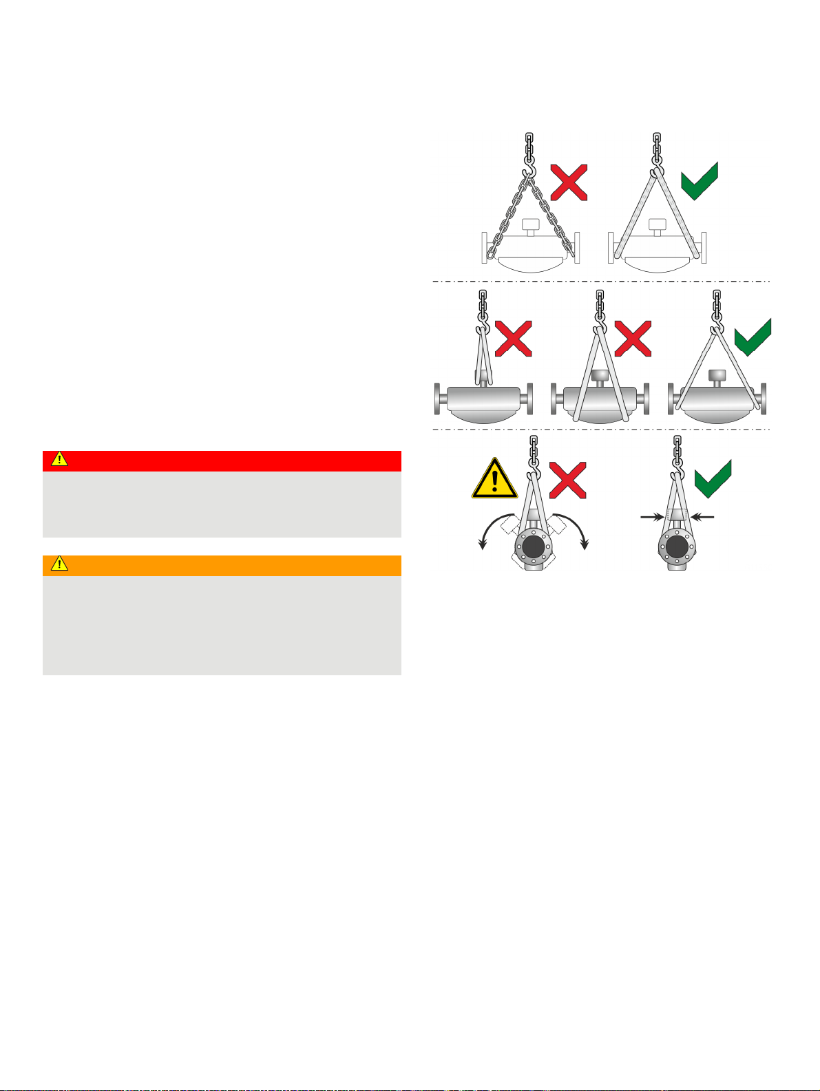
Transporting the device
DANGER
Life-threatening danger due to suspended loads.
In the case of suspended loads, a danger of the load falling
exists.
• Standing under suspended loads is prohibited.
WARNING
Risk of injury due to device slipping.
The device's center of gravity may be higher than the harness
suspension points.
• Make sure that the device does not slip or turn during
transport.
• Support the device laterally during transport.
Figure 8: Transport instructions
Observe the following when transporting the device to the
measuring location:
• Observe the weight details of the device in the data
sheet.
• Use only approved hoisting slings for crane transport.
• Do not lift devices by the transmitter housing or terminal
box.
• The center of gravity of the device may be located above
the harness suspension points.
Page 30

30 CoriolisMaster FCB400, FCH400 CORIOLIS MASS FLOWMETER | OI/FCB400/FCH400-EN REV. E
… 5 Transport and storage
Storing the device
Bear the following points in mind when storing devices:
• Store the device in its original packaging in a dry and
dust-free location.
• Observe the permitted ambient conditions for transport
and storage.
• Avoid storing the device in direct sunlight.
• In principle, the devices may be stored for an unlimited
period. However, the warranty conditions stipulated in
the order confirmation of the supplier apply.
Ambient conditions
The ambient conditions for the transport and storage of the
device correspond to the ambient conditions for operation of
the device.
Adhere to the device data sheet!
Returning devices
For the return of devices, follow the instructions in Repair on
page 138.
Page 31

CoriolisMaster FCB400, FCH400 CORIOLIS MASS FLOWMETER | OI/FCB400/FCH400-EN REV. E 31
6 Installation
General installation conditions
Installation location and assembly
Note the following points when selecting the installation
location and when mounting the sensor:
• The ambient conditions (IP rating, ambient temperature
range T
installation location.
) of the device must be adhered to at the
ambient
• Sensors and transmitters must not be exposed to direct
sunlight. If necessary, provide a suitable means of sun
protection on site. The limit values for ambient
temperature T
must be adhered to.
ambient
• On flange devices, ensure that the counterflanges of the
piping are aligned plane parallel. Only install flange
devices with suitable gaskets.
• Prevent the sensor from coming into contact with other
objects.
• The device is designed for industrial applications.
No special EMC protective measures are required if the
electromagnetic fields and interference at the installation
location of the device comply with ‘Best Practice’ (in
accordance with the standards listed in the declaration of
conformity).
Maintain a suitable distance from electromagnetic fields
and interference that extend beyond the usual
dimensions.
Seals
Users are responsible for selecting and mounting suitable
gaskets (material, shape).
Note the following points when selecting and mounting gaskets:
• Use gaskets made from a material that is compatible
with the measuring medium and measuring medium
temperature.
• Gaskets must not extend into the flow area, since
possible turbulence may influence the accuracy of the
device.
Calculating pressure loss
Pressure loss depends on the properties of the medium and the
flow rate.
A good aid for pressure loss calculation is the Online ABB
Product Selection Assistant (PSA) for flow at
www.abb.com/flow-selector.
Brackets and supports
No special supports or damping are required for the device when
the device is used and installed as intended.
In systems designed in accordance with ‘Best Practice’, the
forces acting on the device are already sufficiently absorbed.
This is also true of devices installed in series or in parallel.
For heavier devices, it is advisable to use additional supports /
brackets on site. Doing this prevents damage to the process
connections and piping from lateral forces.
Please observe the following points:
• Mount two supports or brackets symmetrically in the
immediate vicinity of the process connections.
• Do not fasten any supports or brackets to the housing of
the flowmeter sensor.
Note
For increased vibration load, such as for example on ships, the
use of the ‘CL1’ marine design is recommended.
Inlet section
The sensor does not require any inlet section.
The devices can be installed directly before/after manifolds,
valves or other equipment, provided that no cavitation is caused
by this equipment.
Mounting position
The flowmeter operates in any mounting position.
Depending on the measuring medium (liquid or gas) and the
measuring medium temperature, certain mounting positions are
preferable to others.For this purpose, consider the following
examples.
The preferred flow direction is indicated by the arrow on the
sensor.The flow will be displayed as positive.
The specified measuring accuracy can be achieved only in the
calibrated flow direction (for forward flow calibration, this is
only in the direction of the arrow; for the optional forward flow
and reverse flow calibration, this can be in both flow directions).
Page 32

32 CoriolisMaster FCB400, FCH400 CORIOLIS MASS FLOWMETER | OI/FCB400/FCH400-EN REV. E
… 6 Installation
… General installation conditions
Liquid measuring media
Observe the following points to avoid measuring errors:
• The meter tubes must always be completely filled with
the measuring medium.
• The gases dissolved in the measuring medium must not
leak out. To safeguard this, a minimum back pressure of
0.2 bar (2.9 psi) is recommended.
• The minimum vapor pressure of the measuring medium
must be maintained when there is negative pressure in
the meter tube or when liquids are gently simmering.
• During operation, there must be no phase transitions in
the measuring medium.
Vertical installation
AB
1
2
A For vertical installation in a riser, no special measures are
required.
B For vertical installation in a downpipe, a piping constriction
or an orifice must be installed below the sensor. Doing this
prevents the sensor from draining during the measurement.
Horizontal installation
A
≥ 30°
1 Supply tank
2 Sensor
3 Piping constriction / orifice
Figure 9: Vertical installation
4 Turn-off device
5 Filling tank
3
4
5
G11607
B
Figure 10: Horizontal installation
A For liquid measuring media and horizontal installation, the
transmitter and terminal box must point upward. If a selfdraining installation is required, the sensor must be mounted
at an incline of ≥ 30°.
B Installing the sensor at the highest point of the piping leads
to an increased number of measuring errors due to the
accumulation of air or the formation of gas bubbles in the
meter tube.
G11608-01
Page 33

CoriolisMaster FCB400, FCH400 CORIOLIS MASS FLOWMETER | OI/FCB400/FCH400-EN REV. E 33
Gaseous measuring media
Observe the following points to avoid measuring errors:
• Gases must be dry and free of liquids and condensates.
• Avoid the accumulation of liquids and the formation of
condensate in the meter tube.
• During operation, there must be no phase transitions in
the measuring medium.
If there is a risk of condensate formation when using gaseous
measuring media, note the following:
Ensure that condensates cannot accumulate in front of the
sensor.
If this cannot be avoided, we recommend that the sensor is
installed vertically with a downward flow direction.
Vertical installation
For vertical installation, no special measures are required.
Horizontal installation
Turn-off devices for the zero point
adjustment
A
B
C
1
A
B
G11609
Figure 11: Horizontal installation
A For gaseous measuring media and horizontal installation, the
transmitter and terminal box must point downward.
B Installing the sensor at the lowest point of the piping leads
to an increased number of measuring errors due to the
accumulation of liquid or the formation of condensates in
the meter tube.
1 Turn-off device
Figure 12: Mounting options for turn-off devices (example)
To guarantee the conditions for zero point balancing under
operating conditions, turn-off devices are required in the piping:
A At least on the outlet side when the transmitter is
mounted in horizontal position
B At least on the inlet side when the transmitter is mounted
in vertical position.
C In order to perform balancing during an ongoing process,
it is advisable to mount a bypass pipe.
G11589
Page 34

34 CoriolisMaster FCB400, FCH400 CORIOLIS MASS FLOWMETER | OI/FCB400/FCH400-EN REV. E
… 6 Installation
Sensor insulation
1
aa
C
G11612-02
a80mm≤
(a 3.1 in.)≤
1 Insulation
Figure 13: Installation at T
a
a
−50° to 205 °C (−58 to 400 °F)
medium
The sensor may only be insulated in conjunction with the option
TE1 ‘Extended tower length for sensor insulation’ or TE2
‘Extended tower length – insulation capacity with dual gasket,’
as shown in Figure 13.
Heat tracing of the sensor
When operating the sensor in conjunction with heat tracing, the
temperature at point
C (Figure 13) 100 °C (212 °F) must not be
exceeded at any time!
Installation in EHEDG-compliant installations
WARNING
Risk of poisoning!
Bacteria and chemical substances can contaminate or pollute
pipeline systems and the materials they are made of.
• In EHEDG-compliant installations, the instructions below
must be observed.
• The required self-draining functionality of the sensor can
only be guaranteed when the vertical mounting position or
horizontal mounting position at a 30° incline is used. Refer to
Liquid measuring media on page 32.
• The combination of process connections and gaskets
selected by the operator may comprise only EHEDGcompliant components. Please note the information in the
latest version of the EHEDG Position Paper: ‘Hygienic Process
connections to use with hygienic components and
equipment’ in this regard.
• The pipe fitting in accordance with DIN 11851 is approved for
use in conjunction with an EHEDG-compliant gasket.
Devices for legal metrology in accordance
with MID / OIML R117
The Coriolis mass flowmeters CoriolisMaster FCBx50 / FCHx50
are type-tested for legal metrology in accordance with
MID / OIML R117 in accuracy class 0.3.
Additional information can be found on the corresponding
certificate. The certificate is available in the download area at
www.abb.com/flow.
1 Lead seal
2 Lead seal wire
Figure 14: Sealing in accordance with MID / OIML R117 (example)
On devices for legal metrology in accordance with
MID / OIML R117, the hardware write protection must be
activated after commissioning.
This prevents a change in the parameterization of the devices.
Hardware settings on page 64
To prevent deactivation of the hardware write protection or
other manipulations during operation, the transmitter housing
and the sensor housing connection box (with remote mount
design) must be sealed.
For this purpose, a seal kit is available at ABB.
For the assembly of the seal, please observe the separate
‘IN/FCX100/FCX400/MID/OIML-XA’ instructions.
Page 35

CoriolisMaster FCB400, FCH400 CORIOLIS MASS FLOWMETER | OI/FCB400/FCH400-EN REV. E 35
x
x
Process conditions
Temperature limits °C (°F)
Note
When using the device in potentially explosive atmospheres,
note the additional temperature data in Temperature data on
page 12!
Measuring medium temperature T
medium
• FCx430: −50 to 160 °C (−58 to 320 °F)
• FCx450: −50 to 205 °C (−58 to 401 °F)
In devices with order code ‘Extended tower length – TE3’, the
measuring medium temperature must be limited to a maximum
of 140 °C (284 °F) from an ambient temperature of ≥ 65 °C
(149 °F).
Ambient temperature T
amb.
• Standard: −20 to 70 °C (−4 to 158 °F)
• Optional: −40 to 70 °C (−40 to 158 °F)
Pressure ratings
The maximum permissible operating pressure is determined by
the respective process connection, the temperature of the
medium to be measured, the screws, and the gasket material.
For an overview of available pressure ratings, see Device designs
on page 26.
Housing as a protective device (optional)
Order code PR5
Maximum burst pressure 60 bar (870 psi)
Optional order code PR6 and PR7 on request
• Increased burst pressures up to 100 bar (1450 psi),
possible for nominal diameters DN 15 to 100 (½ to 4 in.).
• Increased burst pressures up to 150 bar (2175 psi),
possible for nominal diameters DN 15 to 80 (½ to 3 in.).
• Purge connections are available on request.
Pressure Equipment Directive
Conformity assessment in accordance with Category III, fluid
group 1, gas
Note the corrosion resistance of the meter tube materials in
relation to the measuring medium.
Material load for process connections
Note
You can reference the availability of the different process
connections in the Online ABB Product Selection Assistant (PSA)
for flow www.abb.com/flow-selector.
• Not all connections shown here are available in all the devices
and designs.
• The permissible material load of the device can additionally
differ from the material load of the connection. The
permissible limit values (pressure rating / measuring
medium temperature T
) can be found on the name
medium
plate.
Design Nominal diameter PS
Pipe fitting
(DIN 11851)
Pipe fitting
(SMS 1145)
Tri-Clamp
(DIN 32676)
ASME BPE Clamp < DN 80
DN 80
DN 100
DN 15 to DN 40
(½ to 1½ in)
DN 50 to DN 100
(2 to 4 in)
DN 25 to DN 80
(1 to 3 in)
DN 15 to DN 50
(½ to 2 in)
DN 65 to DN 100
(2½ to 4 in)
(< 3 in)
(< 3 in)
(< 4 in)
40 bar
(290 psi)
(580 psi)
25 bar
(290 psi)
(363 psi)
6 bar (290
(87 psi)
16 bar (290
(232 psi)
10 bar (290
(145 psi)
17.1 bar
(290 psi)
(248 psi)
15.5 bar
(290 psi)
(224.8 psi)
12.9 bar
(290 psi)
(187.1 psi)
psi)
psi)
psi)
ma
TS
ma
140 °C
(284 °F)
140 °C
(284 °F)
140 °C
(284 °F)
120 °C
(248 °F)
120 °C
(248 °F)
121 °C
(249.8 °F)
121 °C
(249.8 °F)
121 °C
(249.8 °F)
TS
min
−40 °C
(−40 °F)
−40 °C
(−40 °F)
−40 °C
(−40 °F)
−40 °C
(−40 °F)
−40 °C
(−40 °F)
−40 °C
(−40 °F)
−40 °C
(−40 °F)
−40 °C
(−40 °F)
Page 36

36 CoriolisMaster FCB400, FCH400 CORIOLIS MASS FLOWMETER | OI/FCB400/FCH400-EN REV. E
… 6 Installation
… Material load for process connections
Material load curves for flange devices
Figure 15: Stainless steel DIN flange 1.4571 / 1.4404 (316Ti / 316L) to DN 200 (8 in)
Figure 17: Nickel alloy DIN flange C4 (2.4610) or nickel alloy C22 (2.4602) up to DN 200
(8 in.)
Figure 16: Stainless steel ASME flange 1.4571 / 1.4404 (316Ti / 316L) up to DN 200 (8 in.)
Figure 18: Nickel alloy ASME flange C4 (2.4610) or nickel alloy C22 (2.4602) up to DN 200
(in.)
Figure 19: Stainless steel JIS B2220 flange 1.4435 or 1.4404 (AISI 316L) , nickel alloy C4
(2.4610) or nickel alloy C22 (2.4602)
Page 37

CoriolisMaster FCB400, FCH400 CORIOLIS MASS FLOWMETER | OI/FCB400/FCH400-EN REV. E 37
Installing the sensor
Before installation in the piping, observe the installation
conditions and instructions on the mounting position!
1. Insert the sensor into the piping centrally and positioned
coplanar. Use suitable gaskets to seal the process
connections.
2. Tighten flange screws by working on each in a crosswise
manner with the maximum permissible torque.
3. Check the seal integrity of the process connections.
Installing the transmitter in the remote
mount design
When selecting a location for the transmitter, consider the
following points:
• Observe the information concerning maximum ambient
temperature and IP rating on the name plate
• The location must be mostly free from vibration.
• The location must not be exposed to direct sunlight. If
necessary provide a sun screen on site.
• Do not up-scale the maximum signal cable length
between the transmitter and the sensor.
1. Drill mounting holes at mounting location.
2. Attach transmitter securely to the mounting location
using suited fasteners for the base material.
205 (8.0)
168 (6.6)
330 (13.0)
300 (11.8)
Ø 7 (0.28)
1
71 (2.8)
1 Hole pattern for mounting holes
2 Female thread (either ½ in NPT or M20 x 1.5), see model coding. In the
case of a ½ in NPT, there is a plug instead of a cable gland.
Figure 20: Mounting dimensions dual-compartment housing
168 (6.6)
71 (2.8)
G11894-01
Page 38

38 CoriolisMaster FCB400, FCH400 CORIOLIS MASS FLOWMETER | OI/FCB400/FCH400-EN REV. E
… 6 Installation
… Installing the transmitter in the remote
mount design
Opening and closing the housing
DANGER
Danger of explosion if the device is operated with the
transmitter housing or terminal box open!
While using the device in potentially explosive atmospheres
before opening the transmitter housing or the terminal box,
note the following points:
• A valid fire permit must be present.
• Make sure that no flammable or hazardous atmospheres
are present.
WARNING
Risk of injury due to live parts!
When the housing is open, contact protection is not provided
and EMC protection is limited.
• Before opening the housing, switch off the power supply.
NOTICE
Potential adverse effect on the IP rating
• Check the O-ring gasket for damage and replace it if
necessary before closing the housing cover.
• Check that the O-ring gasket is properly seated when
closing the housing cover.
1 Hole pattern for mounting holes
Figure 21: Mounting dimensions single-compartment housing
Page 39

CoriolisMaster FCB400, FCH400 CORIOLIS MASS FLOWMETER | OI/FCB400/FCH400-EN REV. E 39
Dual- compartment housing
Single-compartment housing
A Integral mount design
B Remote mount design
Figure 22: Cover lock (example)
C Transmitter, terminal space,
signal cable
Open the housing:
1. Release the cover lock by screwing in the Allen screw
2. Unscrew cover
1.
Close the housing:
1. Screw on the cover
1.
2. After closing the housing, lock the cover by unscrewing
2.
the Allen screw
2.
1 Cover screws
2 Transmitter housing cover
Figure 23: Open / close single-compartment housing
Open the transmitter housing:
Perform steps
A and B.
Close the transmitter housing:
Perform steps
C and D.
3 Gasket
Page 40

40 CoriolisMaster FCB400, FCH400 CORIOLIS MASS FLOWMETER | OI/FCB400/FCH400-EN REV. E
… 6 Installation
Adjusting the transmitter position
Depending on the installation position, the transmitter housing
or LCD display can be rotated to enable horizontal readings.
Transmitter housing
DANGER
Damaging the device carries a risk of explosion!
When the screws for the transmitter housing are loosened,
the explosion protection is suspended.
Tighten all screws prior to commissioning.
Never disconnect the transmitter housing from the sensor.
Only loosen the screws shown when rotating the transmitter
housing!
Rotate transmitter housing: Perform steps
A to C.
Rotate LCD indicator – dual-compartment housing
The LCD indicator can be rotated in three increments of 90°
each. To open and close the housing, refer to Opening and
closing the housing on page 38.
Turn the LCD indicator:
Perform steps
A to F.
Figure 24: Rotate transmitter housing
Figure 25: Rotating the LCD indicator
Page 41

CoriolisMaster FCB400, FCH400 CORIOLIS MASS FLOWMETER | OI/FCB400/FCH400-EN REV. E 41
Rotate LCD indicator – single-compartment housing
The LCD indicator can be rotated in three increments of 90°
each. To open and close the housing, refer to Opening and
closing the housing on page 38.
Turn the LCD indicator:
Perform steps
A to F.
Figure 26: Rotating the LCD indicator
Change from two to one column
Page 42

42 CoriolisMaster FCB400, FCH400 CORIOLIS MASS FLOWMETER | OI/FCB400/FCH400-EN REV. E
… 6 Installation
Installing the plug-in cards
WARNING
Loss of Ex Approval!
Loss of Ex Approval due to retrofitting of plug-in cards on devices for use in potentially explosive atmospheres.
• Devices for use in potentially explosive atmospheres may not be retrofitted with plug-in cards.
• If devices are to be used in potentially explosive atmospheres, the required plug-in cards must be specified when the order is
placed.
Optional plug-in cards
The transmitter has two slots (OC1, OC2) into which plug-in cards can be inserted to extend inputs and outputs. The slots are located
on the transmitter motherboard and can be accessed after removing the front housing cover.
Plug-in card Description Quantity*
Current output, 4 to 20 mA passive (red)
Order no.: 3KQZ400029U0100
Maximum of two plug-in cards
Passive digital output (green)
Order no.: 3KQZ400030U0100
Passive digital input (yellow)
Order no.: 3KQZ400032U0100
Loop power supply 24 V DC (blue)
Order no.: 3KQZ400031U0100
Modbus RTU RS485 (white)
Order no.: 3KQZ400028U0100
Profibus DP (white)
Order no.: 3KQZ400027U0100
* The ‘Number’ column indicates the maximum number of plug-in cards of the same type that can be used.
Maximum of one plug-in card
Maximum of one plug-in card
Maximum of one plug-in card
Maximum of one plug-in card
Maximum of one plug-in card
Page 43

CoriolisMaster FCB400, FCH400 CORIOLIS MASS FLOWMETER | OI/FCB400/FCH400-EN REV. E 43
The following table provides an overview of the possible plug-in card combinations that can be selected when ordering the device.
Main ordering
information (outputs)
G0 – – – –
G1 – – Loop power supply 24 V DC (blue) –
G2 – – – Passive current output (red)
G3 – – Current output, 4 to 20 mA passive (red) Current output, 4 to 20 mA passive (red)
G4 – – Loop power supply 24 V DC (blue) Passive current output (red)
G0 DRT – Loop power supply 24 V DC (blue) –
G0 DRT DSN Loop power supply 24 V DC (blue) Passive digital input (yellow)
G0 DRT DSG Loop power supply 24 V DC (blue) Passive digital output (green)
G0 DRT DSA Loop power supply 24 V DC (blue) Current output, 4 to 20 mA passive (red)
G0 DRN – Passive digital input (yellow) –
G0 DRN DSG Passive digital input (yellow) Passive digital output (green)
G0 DRN DSA Passive digital input (yellow) Current output, 4 to 20 mA passive (red)
G0 DRG DSN Passive digital output (green) Passive digital input (yellow)
G0 DRG DSA Passive digital output (green) Current output, 4 to 20 mA passive (red)
G0 DRA DSA Current output, 4 to 20 mA passive (red) Current output, 4 to 20 mA passive (red)
G0 DRA DSG Current output, 4 to 20 mA passive (red) Passive digital output (green)
G0 DRA DSN Current output, 4 to 20 mA passive (red) Passive digital input (yellow)
G0 DRM – Modbus RTU RS485 (white) –
G0 DRD – Profibus DP, RS485 (white) –
G0 DRM DSN Modbus RTU RS485 (white) Passive digital input (yellow)
G0 DRM DSG Modbus RTU RS485 (white) Passive digital output (green)
G0 DRD DSN Profibus DP, RS485 (white) Passive digital input (yellow)
G0 DRD DSG Profibus DP, RS485 (white) Passive digital output (green)
Additional ordering information Slot OC1
Additional output 1 Additional output 2
Terminals V1 / V2
Slot OC2
Terminals V3 / V4
Page 44

44 CoriolisMaster FCB400, FCH400 CORIOLIS MASS FLOWMETER | OI/FCB400/FCH400-EN REV. E
… 6 Installation
… Installing the plug-in cards
1 Cover
2 LCD indicator
3 Frontend board (FEB, with integral mount design only)
Figure 27: Installation of plug-in cards (example, dual-compartment housing)
4 Slot OC2
5 Slot OC1
6 Plug-in cards
Page 45

CoriolisMaster FCB400, FCH400 CORIOLIS MASS FLOWMETER | OI/FCB400/FCH400-EN REV. E 45
1 Cover
2 LCD indicator
3 Slot OC1
Figure 28: Installation of plug-in cards (example, single-compartment housing)
Change from one to two columns
WARNING
Risk of injury due to live parts!
When the housing is open, contact protection is not provided
and EMC protection is limited.
• Before opening the housing, switch off the power supply.
NOTICE
Damage to components!
The electronic components of the printed circuit board can be
damaged by static electricity (observe ESD guidelines).
• Make sure that the static electricity in your body is
discharged before touching electronic components.
4 Slot OC2
5 Plug-in cards
1. Switch off the power supply.
2. Unscrew / remove the cover.
3. Remove the LCD indicator. Ensure that the cable harness is
not damaged.
Insert the LCD indicator into the bracket
(only for single-compartment housings)
4. Remove frontend board (only in integral mount design and
dual-compartment housing). Ensure that the cable harness is
not damaged.
5. Insert the plug-in card in the corresponding slot and engage.
Ensure that the contacts are aligned correctly.
6. Attach the frontend board, insert the LCD indicator and
screw on / replace the cover.
7. Connect outputs V1 / V2 and V3 / V4 in accordance with
Electrical connections on page 46.
8. After powering up the power supply, configure the plug-in
card functions.
Page 46

46 CoriolisMaster FCB400, FCH400 CORIOLIS MASS FLOWMETER | OI/FCB400/FCH400-EN REV. E
7 Electrical connections
Safety instructions
WARNING
Risk of injury due to live parts.
Improper work on the electrical connections can result in
electric shock.
• Connect the device only with the power supply switched
off.
• Observe the applicable standards and regulations for the
electrical connection.
The electrical connection may only be established by authorized
specialist personnel and in accordance with the connection
diagrams.
The electrical connection information in this manual must be
observed; otherwise, the IP rating may be adversely affected.
Ground the measurement system according to requirements.
Power supply
Note
• Adhere to the limit values of the power supply in accordance
with the information on the name plate.
• Observe the voltage drop for large cable lengths and small
conductor cross-sections. The voltage at the terminals of the
device may not down-scale the minimum value required in
accordance with the information on the name plate.
The power supply is connected to terminal L (phase), N (zero), or
1+, 2−, and PE.
A circuit breaker with a maximum rated current of 16 A must be
installed in the power supply line.
The wire cross-sectional area of the power supply cable and the
circuit breaker used must comply with VDE 0100 and must be
dimensioned in accordance with the current consumption of the
flowmeter measuring system. The cables must comply with IEC
227 and/or IEC 245.
The circuit breaker must be located near the device and marked
as being associated with the device.
Connect the transmitter and sensor to functional earth.
Page 47

CoriolisMaster FCB400, FCH400 CORIOLIS MASS FLOWMETER | OI/FCB400/FCH400-EN REV. E 47
Installing the connection cables
General information on cable installation
Ensure that a drip loop (water trap) is used when installing the
connecting cables for the sensor.
When mounting the sensor vertically, position the cable entries
at the bottom.
If necessary, rotate the transmitter housing accordingly.
1 Drip loop
Figure 29: Laying the connection cable
Change from two to one column
Signal cable specification
The signal cable used for the connection of the transmitter and
sensor must fulfill at least the following technical specifications.
Cable specification
Impedance 100 to 200 Ω
Withstand voltage 120 V
Outer diameter 6 to 12 mm (0.24 to 0.47 in)
Cable design Two wire pairs as a star-quad cable
Conductor cross-section Length-dependent
Shield Copper braid with approximately 85 % coverage
Temperature range Application-dependent, for use in potentially
explosive atmospheres, observe the information
in Temperature resistance for the connecting
cable on page 12!
Maximum signal cable length
0.25 mm2 (AWG 24) 50 m (164 ft)
0.34 mm2 (AWG 22) 100 m (328 ft)
0.5 mm2 (AWG 20) 150 m (492 ft)
0.75 mm2 (AWG 19) 200 m (656 ft)
Recommended cables
It is recommended to use an ABB signal cable for standard
applications. The ABB signal cable fulfills the above-mentioned
cable specification and can be utilized unrestrictedly up to an
ambient temperature of T
ABB signal cable Ordering number
5 m (16 ft) 3KQZ407123U0500
10 m (33 ft) 3KQZ407123U1000
20 m (65 ft) 3KQZ407123U2000
50 m (164 ft) 3KQZ407123U5000
100 m (328 ft) 3KQZ407123U1H00
150 m (492 ft) 3KQZ407123U1F00
200 m (656 ft) 3KQZ407123U2H00
For marine applications, an appropriate certified signal cable
must be used. ABB recommends the cable HELKAMA RFE-FRHF
2×2×0,75 QUAD 250V (HELKAMA order number 20522).
= 80 °C (176 °F).
amb.
Page 48

48 CoriolisMaster FCB400, FCH400 CORIOLIS MASS FLOWMETER | OI/FCB400/FCH400-EN REV. E
… 7 Electrical connections
Pin assignment
A Transmitter
Figure 30: Electrical connection
Change from one to two columns
Connections for the power supply
AC voltage
Terminal Function / comments
L Phase
N Neutral conductor
PE / Protective earth (PE)
Potential equalization
DC voltage
Terminal Function / comments
1+ +
2- -
PE / Protective earth (PE)
Potential equalization
B Sensor
Connections for inputs and outputs
Terminal Function / comments
Uco / 32
31 / 32
Current output 4 to 20 mA- / HART® output, active
or
Current output 4 to 20 mA- / HART® output, passive
41 / 42 Passive digital output DO1
51 / 52 Passive digital output DO2
V1 / V2
V3 / V4
Plug-in card, slot OC1
Plug-in card, slot OC2
For details, see Optional plug-in cards on page 42.
Connecting the signal cable
Only for remote mount design.
The sensor housing and transmitter housing must be connected
to potential equalization.
Terminal Function / comments
UFE Sensor power supply
GND Ground
A Data line
B Data line
Functional earth / Shielding
Page 49

CoriolisMaster FCB400, FCH400 CORIOLIS MASS FLOWMETER | OI/FCB400/FCH400-EN REV. E 49
… 7 Electrical connections
Electrical data for inputs and outputs
Note
When using the device in potentially explosive atmospheres,
note the additional temperature data in Use in potentially
explosive atmospheres on page 6!
Power supply L / N, 1+ / 2−
AC voltage
Terminals L / N
Operating voltage 100 to 240 V AC, 50 / 60 Hz
Power consumption < 20 VA
DC voltage
Terminals 1+ / 2−
Operating voltage 11 to 30 V DC
Power consumption 20 W
Current output 32 / Uco, 31 / 32 (basic device)
Can be configured for outputting mass flow, volume flow,
density and temperature via on-site software.
AB
IE
+
-
Uco
R
B
32-
31+
A Current output 31 / Uco, active B Current output 31 / 32 passive
Figure 31: (I = internal, E = external, RB = load)
600
500
400
300
RB [Ω]
200
100
0
0
5101520253035
Permissible source voltage Uq for passive outputs in relation to load
resistance R
Figure 32: Source voltage for passive outputs
where I
B
= 22 mA. = Permissible range
max
Current output Active Passive
Terminals Uco / 32 31 / 32
Output signal 4 to 20 mA or
4 to 12 to 20 mA
switchable
Load RB 250 Ω ≤ RB ≤ 300 Ω 250 Ω ≤ RB ≤ 600 Ω
Source voltage Uq* – 13 V ≤ Uq ≤ 30 V
Measuring error < 0.1 % of measured value
Resolution 0.4 µA per digit
* The source voltage Uq is dependent of the load RB and must be placed in an
additional area.
For information on communication via the HART protocol, refer
to HART® Communication on page 61.
-
Uq [V]
IE
+
Uco
32-
31+
4 to 20 mA
Uq
G11596-02
G10323-02
R
B
Page 50

50 CoriolisMaster FCB400, FCH400 CORIOLIS MASS FLOWMETER | OI/FCB400/FCH400-EN REV. E
… 7 Electrical connections
… Pin assignment
Current output Uco / 32 as loop power supply for digital
output 41 / 42 or 51 / 52
A
A
A Transmitter FCx400
B Customer wiring
Figure 33: Current output Uco / 32 in power mode
-
OC1
-
OC1
IE
+
Uco
32-
31+
41+
51+
42-/
52-
V1+
V2-
IE
+
Uco
32-
31+
41+
51+
42-/
52-
V1+
V2-
OC1 Modbus / PROFIBUS DP plug-in
R
A
Modbus /
PROFIBUS DP
B
A
Modbus /
PROFIBUS DP
B
card
Load resistance
B
B
R
B
B
R
B
G12391
In the case of digital communication via Modbus / PROFIBUS DP,
the current output Uco / 32 can be switched to the ‘Power Mode’
operating mode through the software.
The current output 31/32/Uco is set permanently to 22.6 mA and
no longer follows the selected process variable. HART
communication is deactivated.
As a result, the passive digital outputs 41 / 42 or 51 / 52 can also
be operated as active digital outputs.
The load resistance R
outside of the transmitter housing.
Loop power supply 24 V DC pperating mode
Terminals Uco / 32
Function For active connection of passive outputs
Output Voltage Load dependent, see Figure 34.
Load rating I
Table 1: Specification current output Uco / 32 in power mode
22.6 mA, permanently short circuit-proof
max
[V]
30
25
20
15
10
5
0
0 500
22.6 mA
Figure 34: Output voltage dependent on load resistance
needs to be integrated by the customer
B
16 mA
1.00 k 1.50 k 2.00 k
[]Ω
G12393
Page 51

CoriolisMaster FCB400, FCH400 CORIOLIS MASS FLOWMETER | OI/FCB400/FCH400-EN REV. E 51
Digital output 41 / 42, 51 / 52 (basic device)
Can be configured as pulse, frequency or binary output via onsite software.
A
IE
41+
51+
42-/
52-
012345
012345
R
B
R
B
B
IE
41+
51+
42-/
52-
R
B
16...30 V DC
A Digital output 41 / 42, 51 / 52 passive as a pulse of frequency output
B Passive digital output 51 / 52 as binary output
Figure 35: (I = internal, E = external, RB = load)
Pulse / frequency output (passive)
Terminals 41 / 42, 51 / 52
Output ‘closed’ 0 V ≤ U
For f < 2.5 kHz: 2 mA < I
For f > 2.5 kHz: 10 mA < I
Output ‘open’ 16 V ≤ U
0 mA ≤ I
f
10.5 kHz
max
CEL
≤ 3 V
CEH
CEH
≤ 30 V DC
≤ 0.2 mA
< 30 mA
CEL
CEL
< 30 mA
Pulse width 0.1 to 2000 ms
Binary output (passive)
Terminals 41 / 42, 51 / 52
Output ‘closed’ 0 V ≤ U
2 mA ≤ I
Output ‘open’ 16 V ≤ U
0 mA ≤ I
CEL
CEL
CEH
CEH
≤ 3 V
≤ 30 mA
≤ 3 V DC
≤ 0.2 mA
Switching function Can be configured using software.
See Menu: Input / Output on page 107.
Note
• Terminals 42 / 52 have common grounding. Digital outputs
41 / 42 and 51 / 52 are not electrically isolated from each
other. An electrically isolated digital output can be made
using a plug-in module.
• If using a mechanical counter, it is advisable to set a pulse
width of ≥ 30 ms and a maximum frequency of fmax ≤ 3 kHz.
R
16...30 V DC
B
R
B
G11597-02
U
CE
I
CE
U
CE
I
CE
Current output V1 / V2, V3 / V4 (plug-in module)
Up to two additional plug-in modules can be implemented via
the ‘Passive current output (red)’ option module.
Can be configured for outputting mass flow, volume flow,
density and temperature via on-site software.
A
IE
R
OC1
V1+
V2-
A Current output V1 / V2, passive B Current output V3 / V4, passive
Figure 36: (I = internal, E = external, RB = load)
The plug-in module can be used in slot OC1 and OC2.
600
500
400
300
RB [Ω]
200
100
0
0
5101520253035
Permissible source voltage Uq for passive outputs in relation to load
resistance R
Figure 37: Source voltage for passive outputs
where Imax = 22 mA. = Permissible range
B
Passive current output
Terminals V1 / V2, V3 / V4
Output signal 4 to 20 mA
Load RB 250 Ω ≤ RB ≤ 600 Ω
Source voltage Uq* 13 V ≤ Uq ≤ 30 V
Measuring error < 0.1 % of measured value
Resolution 0.4 µA per digit
* The source voltage Uq is dependent of the load RB and must be placed in
an additional area.
B
IE
OC2
V3+
V4-
B
Uq [V]
G11897-02
G10323-02
R
B
Page 52

52 CoriolisMaster FCB400, FCH400 CORIOLIS MASS FLOWMETER | OI/FCB400/FCH400-EN REV. E
… 7 Electrical connections
… Pin assignment
Digital output V1 / V2, V3 / V4 (plug-in module)
An additional binary output can be implemented via the ‘Passive
digital output (green)’ plug-in module.
Can be configured as an output for flow direction signaling,
alarm output etc. via on-site software.
U
CE
R
B
G11898-01
I
CE
OC1
IE
V1+
V2-
R
B
16...30 V DC
16...30 V DC
V3+
OC2
Figure 38: Plug-in card as binary output (I = internal, E = external, RB = load)
V4-
R
B
The plug-in module can be used in slot OC1 or OC2.
Binary output (passive)
Terminals V1 / V2, V3 / V4
Output ‘closed’ 0 V ≤ U
2 mA < I
Output ‘open’ 16 V ≤ U
0 mA ≤ I
Switching function Can be configured using software.
See Menu: Input / Output on page 107.
CEL
≤ 3 V
CEL
CEH
CEH
< 30 mA
≤ 30 V DC
≤ 0.2 mA
Digital output V1 / V2, V3 / V4 (plug-in module)
A digital input can be implemented via the ‘Passive digital input
(yellow)’ plug-in module.
Can be configured as an input for external counter reset,
external output deactivation etc. via on-site software.
IE
V1+
Ri
OC1
OC2
V2-
V3+
Ri
V4-
Figure 39: Plug-in card as digital input (I = internal, E = external)
The plug-in module can be used in slot OC1 or OC2.
Digital input
Terminals V1 / V2, V3 / V4
Input ‘On’ 16 V ≤ UKL ≤ 30 V
Input ‘Off’ 0 V ≤ UKL ≤ 3 V
Internal resistance Ri 6.5 kΩ
Function Can be configured using software.
See Menu: Input / Output on page 107.
16...30 V DC
16...30 V DC
G11598-01
Page 53

CoriolisMaster FCB400, FCH400 CORIOLIS MASS FLOWMETER | OI/FCB400/FCH400-EN REV. E 53
24 V DC loop power supply (plug-in module)
Use of the ‘loop power supply (blue)’ plug-in card allows a
passive output on the transmitter to be used as an active
output. See also Connection examples on page 53.
IE
G12386
+24 V DC
0V
G11739
A
B
V1+
OC1
V2-
Figure 40: (I = Internal, E = External)
The plug-in module can only be used in slot OC1.
Loop power supply 24 V DC
Terminals V1 / V2
Function For active connection of passive outputs
Output Voltage 24 V DC at 0 mA,
17 V DC at 25 mA
Load rating I
25 mA, permanently short circuit-proof
max
Note
If the device is used in potentially explosive atmospheres, the
plug-in card for the loop power supply may only be used to
supply a passive output. It is not allowed, to connect it to
multiple passive outputs!
Modbus / PROFIBUS DP interface V1 / V2 (plug-in card)
A Modbus or PROFIBUS DP interface can be implemented by
using the ‘Modbus RTU, RS485 (white)’ or ‘PROFIBUS DP, RS485
(white)’ plug-in cards.
R
OC1
D
Figure 41: Plug-in card as a Modbus / PROFIBUS DP interface (I = internal, E = external)
IE
V1+
V2-
The corresponding plug-in card can only be used in slot OC1.
For information on communication through the Modbus or
PROFIBUS DP protocols, refer to chapters Modbus®
communication on page 61 and PROFIBUS DP® communication
on page 62.
Connection examples
Input and output functions are configured via the device
software in accordance with the desired application.
Parameter descriptions on page 95
Active digital output 41 / 42, 51 / 52, V3 / V4
When the ‘loop power supply 24 V DC (blue)’ plug-in card is used,
the digital outputs on the basic device and on the option
modules can also be wired as active digital outputs.
Note
Each ‘loop power supply (blue)’ plug-in card must only power one
output.
It must not be connected to two outputs (for example digital
output 41 / 42 and 51 / 52)!
IE
+24 V , max. 25 mADC
V1+
A
OC1
V2-
0V
41+
B
42/52
A ‘Loop power supply (blue)’ plug-in card in slot 1
B Digital output, digital output 41 / 42
Figure 42: Active digital output 41 / 42 (example)
The connection example shows usage for digital output 41 / 42;
the same applies to usage for digital output 51 / 52.
IE
+24 V , max. 25 mADC
V1+
A
OC1
V2-
0V
V3+
B
A ‘Loop power supply (blue)’ plug-in card in slot 1
B ‘Digital output (green)’ plug-in card in slot 2
Figure 43: Active digital output V3 / V4 (example)
OC2
V4-
R
B
012345
G11744-01
R
B
G11913
Page 54

54 CoriolisMaster FCB400, FCH400 CORIOLIS MASS FLOWMETER | OI/FCB400/FCH400-EN REV. E
… 7 Electrical connections
… Pin assignment
Digital output 41 / 42, 51 / 52 passive on distributed
control system
16 ... 30 V DC
A
A Transmitter
B Distributed control system /
Memory programmable controller
Ex. 1 Input 1
Figure 44: Digital output 41 / 42 on distributed control system (example)
IE
41+
51+
42-/
52-
Rx
Rx
Ex.1
Ex.2
0 V DC
Ex. 2 Input 2
R
Resistor for current limitation
X
R
Distributed control system
I
internal resistance
B
Ri
G12366
resistors limit the maximum current through the
The R
X
optoelectronic coupler of the digital outputs in the transmitter.
The maximum permissible current is 25 mA. An R
value of
X
1000 Ω / 1 W is recommended at a voltage level of 24 V DC.
The input on the distributed control system is reduced from
24 V DC to 0 V DC (falling edge) with ‘1’ at the digital output.
Active current output V3 / V4
When the ‘loop power supply 24 V DC, blue’ plug-in card is used,
the current output on the plug-in card can also be wired as the
active current output.
IE
+24 V , max. 25 mADC
V1+
A
OC1
V2-
0V
V3+
B
A ‘Loop power supply (blue)’ plug-in card in slot 1
B ‘Passive current output (red)’ plug-in card in slot 2
Figure 45: Active current output V3 / V4 (example)
OC2
V4-
Digital input V3 / V4 active
When the ‘loop power supply 24 V DC, blue’ plug-in card is used,
the current output on the plug-in card can also be wired as the
active current output.
IE
+24 V , max. 25 mADC
4 ... 20 mA
G11742-01
R
B
V1+
A
OC1
V2-
0V
B
A ‘Loop power supply (blue)’ plug-in card in slot 1
B ‘Passive digital input (yellow)’ plug-in card in slot 2
Figure 46: Active digital output V3 / V4 (example)
OC2
V4-
V3+
G11914
Page 55

CoriolisMaster FCB400, FCH400 CORIOLIS MASS FLOWMETER | OI/FCB400/FCH400-EN REV. E 55
Connection versions digital output 41 / 42, 51 / 52
Depending on the wiring of digital outputs DO 41 / 42 and
51 / 52, they can be used parallel or only individually. The
electrical isolation between the digital outputs also depends on
the wiring.
U
B
B
B
1
2
B
B
+-
U
B
+-
U
B
+-
U
B
+-
G12392
A
IE
41+
51+
42-/
52-
012345
1
012345
R
B
R
B
2
B
IE
41+
51+
42-/
52-
012345
R
012345
R
C
IE
41+
51+
42-/
52-
012345
R
D
IE
41+
51+
42-/
52-
Figure 47: Connection versions digital output 41 / 42 and 51 / 52
012345
R
DO 41 / 42 and 51 / 52 can be
used parallel
A Yes No
B Yes Yes
C No, only DO 41 / 42 can be used No
D No, only DO 51 / 52 can be used No
Table 2: Connection versions digital output
Change from two to one column
DO 41 / 42 and 51 / 52
electrically isolated
Page 56

56 CoriolisMaster FCB400, FCH400 CORIOLIS MASS FLOWMETER | OI/FCB400/FCH400-EN REV. E
3
6
… 7 Electrical connections
… Pin assignment
Connection to integral mount design
Dual- compartment housing
1 Terminals for power supply
2 Cover for power supply terminals
Terminals for inputs and outputs
Figure 48: Connection to device (example), PA = potential equalization
Change from one to two columns
Single-compartment housing
4 Terminal for potential equalization
5 LCD indicator
Bracket for LCD indicator (park position)
Page 57

CoriolisMaster FCB400, FCH400 CORIOLIS MASS FLOWMETER | OI/FCB400/FCH400-EN REV. E 57
NOTICE
If the O-ring gasket is seated incorrectly or damaged, this
may have an adverse effect on the housing protection class.
Follow the instructions in Opening and closing the housing
on page 38 to open and close the housing safely.
Observe the following points when connecting to an electrical
supply:
• Lead the power supply cable into the housing through the
top cable entry.
• Lead the cables for signal inputs and signal outputs into
the housing through the middle and, where necessary,
bottom cable entries.
• Connect the cables in accordance with the electrical
connection. If present, connect the cable shielding to the
earthing clamp provided.
• Use wire end ferrules when connecting.
• After connecting the power supply to the dual-
compartment housing, terminal cover
installed.
• Close unused cable entries using suited plugs.
Change from two to one column
2 must be
Page 58

58 CoriolisMaster FCB400, FCH400 CORIOLIS MASS FLOWMETER | OI/FCB400/FCH400-EN REV. E
… 7 Electrical connections
… Pin assignment
Connection to remote mount design
Transmitter
Dual- compartment housing
A Upper terminal box (back side)
B Lower terminal box
C Signal cable to sensor
1 Terminals for power supply
Figure 49: Electrical connection to transmitter in remote mount design [example, dimensions in mm (in)]
2 Cover for power supply terminals
3 Terminals for signal cable
4 Terminals for inputs and outputs
5 Terminal for potential equalization
Page 59

CoriolisMaster FCB400, FCH400 CORIOLIS MASS FLOWMETER | OI/FCB400/FCH400-EN REV. E 59
Single-compartment housing
A Signal cable to sensor
1 Terminals for power supply
2 Terminals for inputs and outputs (base device)
3 Terminals for signal cable
Figure 50: Electrical connection to transmitter in remote mount design [example, dimensions in mm (in)]
Change from one to two columns
NOTICE
If the O-ring gasket is seated incorrectly or damaged, this
may have an adverse effect on the housing protection class.
Follow the instructions in Opening and closing the housing
on page 38 to open and close the housing safely.
Terminal ABB signal cable
3KQZ407123U0100
HELKAMA signal cable
20522
4 Terminals for inputs and outputs (plug-in cards)
5 Terminal for potential equalization
6 LCD indicator
7 Bracket for LCD indicator (park position)
Observe the following points when connecting to an electrical
supply:
• Lead the cable for the power supply and the signal inputs
and outputs into the housing as shown.
• The signal cable to the sensor is connected in the lower
connection area of the transmitter.
• Connect the cables in accordance with the electrical
connection diagram. If present, connect the cable shielding
to the earthing clamp provided.
• Use wire end ferrules when connecting.
• After connecting the power supply, terminal cover
be installed.
GND Blue Blue (4)
UFE White white (3)
A Yellow Blue (2)
B Orange white (1)
Change from two to one column
• Close unused cable entries using suitable plugs.
2 must
Page 60

60 CoriolisMaster FCB400, FCH400 CORIOLIS MASS FLOWMETER | OI/FCB400/FCH400-EN REV. E
… 7 Electrical connections
… Pin assignment
Flowmeter sensor
A Signal cable from the sensor
2 Terminals for signal cable
1 Terminal for potential equalization
Figure 51: Connection to sensor in remote mount design (example)
Change from one to two columns
NOTICE
If the O-ring gasket is seated incorrectly or damaged, this
may have an adverse effect on the housing protection class.
Follow the instructions in Opening and closing the housing
Observe the following points when connecting to an electrical
supply:
• Lead the signal cable into the housing as shown.
• Connect the cables in accordance with the electrical
on page 38 to open and close the housing safely.
Terminal ABB signal cable
3KQZ407123U0100
HELKAMA signal cable
20522
• Use wire end ferrules when connecting.
• From an ambient temperature of T
• Close unused cable entries using suited plugs.
GND Blue Blue (4)
UFE White white (3)
A Yellow Blue (2)
B Orange white (1)
connection. If present, connect the cable shielding to the
earthing clamp provided.
≥ 60 °C (≥ 140 °F)
amb.
additionally insulate the wires with the enclosed silicone
hoses.
Page 61

CoriolisMaster FCB400, FCH400 CORIOLIS MASS FLOWMETER | OI/FCB400/FCH400-EN REV. E 61
Digital communication
HART® Communication
Note
The HART® protocol is an unsecured protocol, as such the
intended application should be assessed to ensure that these
protocols are suitable before implementation.
In connection with the DTM (Device Type Manager) available to
the device, communication (configuration, parameterization)
can be carried out FDT 0.98 or 1.2 (DSV401 R2).
Other tool or system integrations (e.g. Emerson AMS / Siemens
PCS7) on request.
The necessary DTMs and other files can be downloaded from
www.abb.com/flow.
HART output
Terminals Active: Uco / 32
Passive: 31 / 32
Protocol HART 7.1
Transmission FSK modulation on current output 4 to 20 mA in
accordance with the Bell 202 standard
Baud rate 1200 baud
Signal amplitude Maximum 1.2 mAss
Factory setting of the HART process variables
HART process variable Process value
Primary Value (PV) Q
Secondary Value (SV) Qv – Volume flow rate
Tertiary Value (TV) p – Density
Quaternary Value (QV) Tm – Measuring medium temperature
– Mass flow
m
The process values of the HART variables can be set in the device
menu.
Modbus® communication
Note
The Modbus® protocol is an unsecured protocol, as such the
intended application should be assessed to ensure that these
protocols are suitable before implementation.
Modbus is an open standard owned and administrated by an
independent group of device manufacturers styled the Modbus
Organization (www.modbus.org).
Using the Modbus protocol allows devices made by different
manufacturers to exchange information via the same
communication bus, without the need for any special interface
devices to be used.
Modbus protocol
Terminals V1 / V2
Configuration Via the Modbus interface or via the local operating
interface in connection with Asset Vision Basic
(DAT200) and a corresponding Device Type Manager
(DTM)
Transmission Modbus RTU - RS485 serial connection
Baud rate 2400, 4800, 9600, 19200, 38400, 56000, 57600,
115200 baud
Factory setting: 9600 baud
Parity None, even, odd
Factory setting: odd
Stop bit One, two
Factory setting: One
IEEE format Little endian, big endian
Factory setting: Little endian
Typical response time < 100 ms
Response delay time 0 to 200 milliseconds
Factory setting: 10 milliseconds
Page 62

62 CoriolisMaster FCB400, FCH400 CORIOLIS MASS FLOWMETER | OI/FCB400/FCH400-EN REV. E
… 7 Electrical connections
… Digital communication
1
D
R
2
120 Ω
R
D
3
1 Modbus master
2 Terminating resistor
Figure 52: Communication with the Modbus protocol
R
D
4
3 Modbus slave 1
4 Modbus slave n to 32
A
B
GND
2
120 Ω
G11603
Cable specification
The maximum permissible length is dependent on the baud rate,
the cable (diameter, capacity and surge impedance), the number
of loads in the device chain, and the network configuration
(2-core or 4-core).
• At a baud rate of 9600 and with a conductor cross-section of
2
at least 0.14 mm
(AWG 26), the maximum length is 1000 m
(3280 ft).
• When using a 4-core cable as a 2-wire wiring system, the
maximum length must be halved.
• The spur lines must be short, a maximum of 20 m (66 ft).
• When using a distributor with ‘n’ connections, each branch
must have a maximum length of 40 m (131 ft) divided by ‘n.’
The maximum cable length depends on the type of cable used.
The following standard values apply:
• Up to 6 m (20 ft):
cable with standard shielding or twisted-pair cable.
• Up to 300 m (984 ft):
double twisted-pair cable with overall foil shielding and
integrated earth cable.
• Up to 1200 m (3937 ft):
double twisted-pair cable with individual foil shielding and
integrated earth cables. Example: Belden 9729 or equivalent
cable.
A category 5 cable can be used for Modbus RS485 up to a
maximum length of 600 m (1968 ft). For the symmetrical pairs in
RS485 systems, a surge impedance of more than 100 Ω is
preferred, especially at a baud rate of 19200 and above.
PROFIBUS DP® communication
Note
The PROFIBUS DP® protocol is an unsecured protocol, as such
the intended application should be assessed to ensure that
these protocols are suitable before implementation.
PROFIBUS DP interface
Terminals V1 / V2
Configuration Via the PROFIBUS DP interface or via the local
operating interface in connection with Asset Vision
Transmission In accordance with IEC 61158-2
Baud rate 9.6 kbps, 19.2 kbps, 45.45 kbps, 93.75 kbps, 187.5
Device profile PA Profile 3.02
Bus address Address range 0 to 126
For commissioning purposes, you will need a device driver in
EDD (Electronic Device Description) or DTM (Device Type
Manager) format plus a GSD file.
You can download EDD, DTM and GSD from www.abb.com/flow.
The files required for operation can also be downloaded from
www.profibus.com.
ABB provides three different GSD files which can be integrated in
the system.
ID number GSD file name
0x9740 PA139740.gsd 1xAI, 1xTOT
0x9700 PA139700.gsd 1AI
0x3432 ABB_3432.gsd 6xAI, 2xTOT, 1xAO, 1xDI,
Users decide at system integration whether to install the full
range of functions or only part. Switching is made using the
‘Ident Nr. Selector’ parameter.
See also Ident Nr. Selector on page 114.
Basic (DAT200) and a corresponding Device Type
Manager (DTM)
kbps, 500 kbps, 1.5 Mbps
The baud rate is automatically detected and does not
need to be configured manually
Factory setting: 126
1xDO
Page 63

CoriolisMaster FCB400, FCH400 CORIOLIS MASS FLOWMETER | OI/FCB400/FCH400-EN REV. E 63
Limits and rules when using ABB fieldbus accessories
Figure 53: Bus cable length depends on the transmission rate
Pro PROFIBUS Line
(Line = Starts at DP Master and goes to last DP/PA Slave)
• Approximately 4 to 8 DP segments through the repeater (see
repeater data sheets)
• Recommended DP transfer rate 500 to 1500 kBit/s
• The slowest DP node determines the transfer rate of the DP
line
• Number of PROFIBUS DP and PA nodes ≤ 126 (addresses
0 to 125)
Per PROFIBUS DP segment
• Number of DP nodes ≤ 32
(Node = Devices with / without PROFIBUS address)
• Bus termination required at the beginning and end of each
DP segment!
• Trunk cable length (L
transfer rate)
• Cable length of at least 1 m between two DP nodes at
≥ 1500 kBit/s!
• Spur cable length (L
at > 1500 kBit/s: LS = 0.00 m!
• At 1500 kBit/s and ABB DP cable type A:
– Sum of all spur cable lengths (L
length (L
maximum 22 DP nodes (= 6.60 m / (0.25 m + 0.05 m
spare))
) > 6.60 m, total length = LT+ (Σ LS) ≤ 200 m,
T
) see diagram (length dependent on
T
), at ≤ 1500 kBit/s: LS ≤ 0.25 m,
S
) ≤ 6.60 m, trunk cable
S
Page 64

64 CoriolisMaster FCB400, FCH400 CORIOLIS MASS FLOWMETER | OI/FCB400/FCH400-EN REV. E
8 Commissioning
DANGER
Explosion hazard
Improper installation and commissioning of the device carries
a risk of explosion.
• For use in potentially explosive atmospheres, observe the
information in Use in potentially explosive atmospheres
on page 6!
CAUTION
Risk of burns due to hot measuring media
The device surface temperature may exceed 70 °C (158 °F),
depending on the measuring medium temperature!
• Before starting work on the device, make sure that it has
cooled sufficiently.
Hardware settings
Dual- compartment housing
1 NAMUR DIP switch 2 Write protection DIP switch
Figure 54: Position of the DIP switches
DIP switches are located behind the front housing cover. The DIP
switches are used to configure specific hardware functions. The
power supply to the transmitter must be briefly interrupted in
order for the modified setting to take effect.
Write-protect switch
When write protection is activated, device parameterization
cannot be changed via the LCD indicator. Activating and sealing
the write protection switch protects the device against
tampering
Number Function
On Write protection active
Off Write protection deactivated.
Configuration of digital outputs 41 / 42 and 51 / 52
The configuration (NAMUR, optoelectronic coupler) for the
digital outputs on the basic device is set via DIP switches in the
transmitter.
Number Function
On Digital output 41 / 42 and 51 / 52 as
NAMUR output.
Off Digital output 41 / 42 and 51 / 52 as
optoelectronic coupler output.
Page 65

CoriolisMaster FCB400, FCH400 CORIOLIS MASS FLOWMETER | OI/FCB400/FCH400-EN REV. E 65
Single-compartment housing
1 DIP switch, Write protection
Figure 55: Position of the DIP switch
The DIP switches are used to configure specific hardware
functions. The power supply to the transmitter must be briefly
interrupted or the device reset in order for the modified setting
to take effect.
Write-protect switch
When write protection is activated, device parameterization
cannot be changed via the LCD indicator. Activating and sealing
the write protection switch protects the device against
tampering.
Number Function
On Write protection active
Off Write protection deactivated.
Configuration of digital outputs V1 / V2 or V3 / V4
1 NAMUR rotary switch
Figure 56: Position of rotary switch on the plug-in card
The configuration (NAMUR, optoelectronic coupler) for the
digital output on the plug-in card is set via a rotary switch on the
plug-in card.
Number Function
On Digital output V1 / V2 or V3 / V4 as
Off Digital output V1 / V2 or V3 / V4 as
NAMUR output.
optoelectronic coupler output.
Page 66

66 CoriolisMaster FCB400, FCH400 CORIOLIS MASS FLOWMETER | OI/FCB400/FCH400-EN REV. E
… 8 Commissioning
Checks prior to commissioning
The following points must be checked before commissioning the
device:
• Correct wiring in accordance with Electrical connections
on page 46.
• Correct grounding of the sensor.
• The ambient conditions must meet the requirements set
out in the specification.
• The power supply must meet the requirements set out on
the name plate.
Switching on the power supply
• Switch on the power supply.
The LCD display shows the following display during the startup
process:
System Startup
Processing
The process display is displayed after the startup process.
Parameterization of the device
The CoriolisMaster FCB400, FCH400 can be commissioned and
operated via the integrated LCD indicator (see chapter Menu:
Easy Set-up on page 70).
Alternatively, the CoriolisMaster FCB400, FCH400 can also be
commissioned and operated via standard HART tools. These
include:
• ABB HART handheld terminal DHH805 (FCB4xx EDD)
• ABB Asset Vision Basic (FCB4xx DTM)
• ABB 800xA control system (FCB4xx DTM)
• Other tools supporting standard HART EDDs or DTMs
(FDT1.2)
Note
Not all tools and frame applications support DTMs or EDDs at
the same level. In particular, optional or advanced EDD / DTM
functions may not be available on all tools. ABB provides frame
applications supporting the full range of functions and
performance.
Installation of ABB AssetVision Basic and ABB Field
Information Manager (FIM)
There are two different software packages available for
configuration:
• ABB AssetVision Basic combined with the ABB
CoriolisMaster Device Type Manager (DTM).
• ABB Field Information Manager (FIM) combined with the
ABB CoriolisMaster Field Device Information Package (FDI
package).
Page 67

CoriolisMaster FCB400, FCH400 CORIOLIS MASS FLOWMETER | OI/FCB400/FCH400-EN REV. E 67
AssetVision Basic with the ABB CoriolisMaster Device Type
Manager (DTM)
The required software and drivers can be downloaded
using the adjacent download link.
Installation of the software and connection to the flowmeter:
1. Unpack the downloaded archive file to the c:\temp folder.
2. AssetVision Basic (DAT200) install
‘3KXD151200S0050_Tool_DAT200_Asset_Vision_Basic’.
3. HART Communication DTM install
‘CWCommDTMHART_1.0.55’.
4. CoriolisMaster DTM FCXxxx install
"3KXF410100S0002_DTM_FCXxxx_HART_CoriolisMaster‘.
5. Connect the flowmeter with the PC / laptop, see chapter
Parameterization via the infrared service port adapter on
page 69 or Parameterization via HART® on page 69.
6. Power-up the power supply for the flowmeter and start
AssetVision Basic on the PC / laptop
• Select HART and ‘HART Communication Version 1.0.52’.
• Select ‘Extended HART modem’.
• Select the corresponding COM port.
• Activate the ‘Multimaster and Burst mode support’
option.
• The flowmeter is detected and the CoriolisMaster DTM
starts automatically.
• Confirm the dialog field ‘Upload parameters’ by selecting
‘yes’.
COM settings
Baud rate 19200
Number of Stop bits 1
RTS Control Toggle
DTR Control Enable
Parity Odd
Master Primary Master
Preamble 5
Number of communication retries 3
Start Address 0
End Address 0
Communication timeout 10 s
Page 68

68 CoriolisMaster FCB400, FCH400 CORIOLIS MASS FLOWMETER | OI/FCB400/FCH400-EN REV. E
… 8 Commissioning
… Parameterization of the device
Field Information Manager (FIM) with the ABB
CoriolisMaster Field Device Information Package
Download the ABB Field Information Manager (FIM) using
the adjacent download link.
Download the ABB FDI package using the adjacent
download link.
Installation of the software and connection to the flowmeter:
1. Install ABB Field Information Manager (FIM).
2. Unpack the ABB FDI package into the c:\temp folder.
3. Connect the flowmeter with the PC / laptop, see chapter
Parameterization via the infrared service port adapter on
page 69 or Parameterization via HART® on page 69.
4. Power-up the power supply for the flowmeter and start the
ABB Field Information Manager (FIM).
5. Drag and drop the ‘ABB.FCXxxx.01.00.00.HART.fdix’ file to the
ABB Field Information Manager (FIM). No special view is
needed for this.
1
6. Right-click
as shown in Figure 57.
Figure 58: Select FIM – COM-Port
8. Select the corresponding COM port. Close the menu by
clicking on “send”.
9. By using the menu button on the left side, the
flowmeter is displayed under ‘TOPOLOGY’.
Figure 57: Select FIM – ‘Device Settings’
7. Select ‘DEVICE SETTINGS’
2
as shown in Figure 57.
Figure 59:
All the submenus can be accessed by clicking the three points
below the tag name of the flowmeter with the left mouse
1
.
button
Page 69

CoriolisMaster FCB400, FCH400 CORIOLIS MASS FLOWMETER | OI/FCB400/FCH400-EN REV. E 69
Parameterization via the infrared service port adapter
Configuration via the infrared service port adapter on the device
requires a PC / notebook and the FZA100 infrared service port
adapter.
By combining the HART-DTM and the software ‘ABB AssetVision’
available at www.abb.com/flow, all parameters can also be set
without a HART connection.
1 Infrared service port adapter
2 USB-interface cable
Figure 60: Infrared service port adapter on the transmitter (example)
1. Position the infrared service port adapter on the front plate
of the transmitter as shown
2. Insert USB interface cable into a free USB female connector
on the PC / notebook.
3. Switch on the device power supply.
4. Start ABB AssetVision and perform the parameterization of
the equipment.
Detailed information on operating the software is available in
the relevant operating instructions and the DTM online help.
Change from two to one column
3 PC / Notebook running ABB
AssetVision and HART DTM
Parameterization via HART®
Configuration via the HART interface of the device requires a
PC / Notebook and a suited HART® Modem.
All parameters can also be set via the HART protocol, using the
HART DTM available at www.abb.com/flow and the ABB
AssetVision software.
1 PC / Notebook running ABB
AssetVision and HART DTM
2 HART modem
Figure 61: HART Modem on the transmitter (example)
For more detailed information on operating the software and
the HART modem, please refer to the relevant operating
instructions and the DTM online help.
3 Power supply unit
Page 70

70 CoriolisMaster FCB400, FCH400 CORIOLIS MASS FLOWMETER | OI/FCB400/FCH400-EN REV. E
… 8 Commissioning
Basic Setup
The device can be factory parameterized to customer specifications upon request. If no customer information is available, the device
is delivered with factory settings.
Settings for the most common parameters are summarized in the ‘Easy Set-up’ menu.
This menu is the quickest way to perform the initial configuration of the device.
For information on navigating through the transmitter menu, see Menu navigation on page 72.
For a detailed description of all menus / parameters see Parameter descriptions on page 95.
Menu: Easy Set-up
Menu / parameter Description
Easy Set-up
Language Selection of menu language.
Unit Massflow Qm Selection of the unit for mass flow rate (for example for the QmMax / QmMaxDN parameters and for the corresponding
process value).
See Table 2: Units for mass flow on page 78.
Qm Max Sets the upper range value for the mass flow for forward and reverse flow. The value is also used to calculate the
corresponding percentage value.
Unit Volumeflow Qv Selection of the unit for volume flow rate (for example for the QvMax / QvMaxDN parameters and for the corresponding
process value).
See Table 1: Units for the volume flow rate on page 78.
Qv Max Setting of the upper measuring range value 1 for the volume flow for feed flow and reverse flow. The value is also used to
calculate the corresponding percentage value.
Density Selection of the unit for the density (e.g. for the associated parameters and the corresponding process values).
See Table 3: Density units on page 78.
Density Max Sets the maximum / minimum density to be measured. This value is used to calculate the percentage density value. These
Density Min
parameters are only available if the density output ‘Density [unit]’ was selected when configuring the power and digital
outputs.
Unit Temperature Selection of unit for temperature (e.g. for the associated parameters and the corresponding process values).
See Table 4: Temperature units on page 78.
Unit Mass Totalizer Selection of the unit for the mass counters and the pulse outputs.
See Table 6: Units for the mass totalizer on page 79.
Unit Vol. Totalizer Selection of the unit for the volume totalizers and the pulse outputs.
See Table 7: Units for the volume totalizer on page 79.
Curr.Out 31 / 32 / Uco Selection of the process value issued via the current output.
Curr.Out V1 / V2
Curr.Out V3 / V4
The current outputs V1 / V2 and V3 / V4 are only available if the corresponding plug-in cards are present!
Available process variables on page 80
Dig.Out 41 / 42 Mode Selection of the operating mode for the digital output 41 / 42.
• Off: Digital output 41 / 42 deactivated.
• Logic: Digital output 41 / 42 as a binary output (e.g. as an alarm output).
• Pulse: Digital output 41 / 42 as a pulse output. In pulse mode, pulses per unit are output (e.g. 1 pulse per m
3
).
• Frequency: Digital output 41 / 42 as a frequency output. In frequency mode, a frequency is issued that is proportional to
the flow rate. The maximum frequency can be configured in accordance with the upper range value.
Page 71

CoriolisMaster FCB400, FCH400 CORIOLIS MASS FLOWMETER | OI/FCB400/FCH400-EN REV. E 71
Menu / parameter Description
Easy Set-up
Dig.Out 51 / 52 Mode Selection of the operating mode for the digital output 51 / 52.
• Off: Digital output deactivated.
• Logic: Digital output functions as binary output (for function see parameter ‘„...Setup Logic Output’).
• Follow DO 41 / 42: The digital output 51 / 52 follows the function of digital output 41 / 42. Depending on the setting of
the parameter ‘Input / Output / ...Dig.Out 51 / 52 / Outp. Flow Direction’, digital output 51 / 52 is operated in pulse
mode as follows:
- No pulses are issued if ‘Forward & Reverse’ is selected. Only digital output 41 / 42 is active.
- If ‘Forward’ is selected, pulses for forward flow are issued on digital output 41 / 42, while pulses for reverse flow are
issued on digital output 51 / 52.
- If ‘Reverse’ is selected, pulses for reverse flow are issued on digital output 41 / 42, while pulses for forward flow are
issued on digital output 51 / 52.
• 90° Shift: Output of the same pulses as for digital output 41 / 42, phase shifted by 90°.
• 180° Shift: Output of the same pulses as for digital output 41 / 42, phase shifted by 180°
Dig.Out V1 / V2 Mode Selection of the operating mode for digital output V1 / V2.
Digital output V1 / V2 is only available if the corresponding plug-in card is present!
• Off: Digital output V1 / V2 deactivated.
• Logic: Digital output V1 / V2 as a binary output (for example, as an alarm output).
Dig.Out V3 / V4 Mode Selection of the operating mode for digital output V3 / V4.
Digital output V3 / V4 is only available if the corresponding plug-in card is present!
• Off: Digital output V3 / V4 deactivated.
• Logic: Digital output V3 / V4 as a binary output (for example, as an alarm output).
Dig.Out 41 / 42 Freq. Selection of process value issued via the frequency or pulse output.
Dig.Out 41 / 42 Pulse
Dig.Out 41 / 42 Logic
Dig.Out 51 / 52 Logic
Dig.Out V1 / V2 Logic
Dig.Out V3 / V4 Logic
Pulses per Unit
Pulse Width
Upper Frequency Sets the upper range value frequency for the digital output operating mode ‘Frequency’. The entered value corresponds to
System Zero Starts the automatic zero point balancing using . Automatic zero point balancing takes approx. 60 seconds.
Change from one to two columns
Only if digital output 41 / 42 has been configured as a frequency or pulse output.
Available process variables on page 80
Selection of the output function for the relevant binary output.
• F / R Signal: The binary output signals the flow direction.
• Dual Range: The binary output is activated when measuring range 2 (QmMax 2 / QvMax 2) is selected. This selection is
only available if the parameter ‘Range Mode Config’ has been configured to Qm or Qv.
• Batch End Contact: The binary output is activated when the set fill quantity is reached (only if the FillMass function is
activated).
Only if the relevant digital output has been configured as a binary output.
Set pulses per volume or per mass flow unit, and the pulse width for the digital output operating mode ‘Pulse’.
Only available if a digital output has been configured as a pulse output, and the volume flow or mass flow has been selected
as the process variable to be output.
100 % flow.
Only available if a digital output has been configured as a frequency output, and the volume flow or mass flow has been
selected as the process variable to be output.
Note
Prior to starting the zero point adjustment, make sure that:
• There is no flow through the sensor (close all valves, shut-off devices etc.)
• The sensor must be filled completely with measuring medium for measurement.
Page 72

72 CoriolisMaster FCB400, FCH400 CORIOLIS MASS FLOWMETER | OI/FCB400/FCH400-EN REV. E
5
5
9 Operation
Safety instructions
CAUTION
Risk of burns due to hot measuring media
The device surface temperature may exceed 70 °C (158 °F),
depending on the measuring medium temperature!
• Before starting work on the device, make sure that it has
cooled sufficiently.
If there is a chance that safe operation is no longer possible,
take the device out of operation and secure it against
unintended startup.
Menu navigation
1
M10145-01
2
1 Operating buttons for menu
navigation
2 Menu name display
3 Menu number display
Figure 62: LCD display
Change from two to one column
Exit Select
Menu
3
4
4 Marker for indicating relative
position within the menu
5 Display showing the current
functions of the and
operating buttons
The LCD indicator has capacitive operating buttons. These
enable you to control the device through the closed housing
cover.
Note
The transmitter automatically calibrates the capacitive buttons
on a regular basis. If the cover is opened during operation, the
sensitivity of the buttons is firstly increased to enable operating
errors to occur. The button sensitivity will return to normal
during the next automatic calibration.
You can use the or operating buttons to browse through
the menu or select a number or character within a parameter
value.
Different functions can be assigned to the and operating
buttons. The function
shown on the LCD display.
Control button functions
Meaning
Exit Exit menu
Back Go back one submenu
Cancel Cancel a parameter entry
Next Select the next position for entering numerical and
Meaning
Select Select submenu / parameter
Edit Edit parameter
OK Save parameter entered
5 that is currently assigned to them is
alphanumeric values
Page 73

CoriolisMaster FCB400, FCH400 CORIOLIS MASS FLOWMETER | OI/FCB400/FCH400-EN REV. E 73
Menu levels
Process display
Information level
Input / Output
Process Alarm
Communication
Diagnostics
Totalizer
(Operator Menu)
...Operator Page 1 … 4 Easy Set-up
Autoscroll Device Info
Diagnostics Device Setup
Signals View Display
Configuration level
(Configuration)
Process display
The process display shows the current process values.
From the level of the process display, you can branch out into two menu levels (information level, configuration level).
Information level (Operator Menu)
The information level contains the parameters and information that are relevant for the operator.
The device configuration cannot be changed on this level.
Configuration level (Configuration)
The configuration level contains all the parameters required for device commissioning and configuration. The device configuration
can be changed on this level. For additional information on the parameters, see Parameter descriptions on page 95.
Change from one to two columns
Page 74

74 CoriolisMaster FCB400, FCH400 CORIOLIS MASS FLOWMETER | OI/FCB400/FCH400-EN REV. E
… 9 Operation
Process display
1 Measuring point tagging
2 Current process values
Figure 63: Process display (example)
The process display appears on the LCD display when the device
is powered on. It shows information about the device and
current process values.
The way in which the current process values are shown can be
adjusted on the configuration level.
The symbols at the bottom of the process display are used to
indicate the functions of the operating buttons and , in
addition to other information.
Symbol Description
/ Call up information level.
When Autoscroll mode is activated, the icon appears here
and the operator pages are automatically displayed one after
the other.
Call up configuration level.
The device is protected against changes in the
parametrization.
3 ‘Button function’ symbol
4 ‘Parameterization protected’
symbol
Switching to the information level
On the information level, the operator menu can be used to
display diagnostic information and choose which operator
pages to display.
Process display
1. Open the using Operator Menu.
Operator Menu
Diagnostics
Operator Page 1
Operator Page 2
2. Select the desired submenu using / .
3. Confirm the selection with .
Menu Description
… / Operator Menu
Diagnostics Selection of sub-menu ‘Diagnostics’; see also Error
messages on the LCD display on page 75.
Operator Page 1 to n Selection of operator page to be displayed.
Autoscroll When ‘Autoscroll‘ is activated, automatic switching
of the operator pages is initiated on the process
screen.
Signals View Selection of submenu ‘Signals View’ (only for service
purposes).
Page 75

CoriolisMaster FCB400, FCH400 CORIOLIS MASS FLOWMETER | OI/FCB400/FCH400-EN REV. E 75
Error messages on the LCD display
In the event of an error, a message consisting of a symbol and
text (e.g. Electronics) appears at the bottom of the process
screen.
The text displayed provides information about the area in which
the error has occurred.
Process display
Electronics
The error messages are divided into four groups in accordance
with the NAMUR classification scheme. The group assignment
can only be changed using a DTM or EDD:
Symbol Description
Error / failure
Function check
Outside of the specification
Maintenance required
The error messages are also divided into the following areas:
Range Description
Operation Error / alarm due to the current operating
conditions.
Sensor Error / alarm of the flowmeter sensor.
Electronics Error / alarm of the electronics.
Configuration Error / alarm due to device configuration.
Note
For a detailed description of errors and troubleshooting
instructions, please see Diagnosis / error messages on
page 131.
Switching to the information level
The device parameters can be displayed and changed on the
configuration level.
Process display
1. Switch to the configuration level with .
Access Level
Read Only
Standard
Service
Back Select
2. Select the desired level of access using / .
3. Confirm the selection with .
Note
There are three levels of access. A password can be defined for
level ‘Standard’.
• There is no factory default password. For security reasons it
is recommended to set a password.
• The password prevents access to the parameterization via
the buttons on the device. For further access protection via
DTM or EDD (HART®, PROFIBUS®, Modbus®) the hardware
write protection switch must be set (see Hardware settings
on page 64).
Access Level Description
Read Only All parameters are locked. Parameters are read only and
cannot be modified.
Standard All the parameters can be changed.
Service Only ABB Customer Service has access to the Service
menu.
Page 76

76 CoriolisMaster FCB400, FCH400 CORIOLIS MASS FLOWMETER | OI/FCB400/FCH400-EN REV. E
K
… 9 Operation
… Switching to the information level
Once you have logged on to the corresponding access level, you
can edit or reset the password. Reset (status ‘no password
defined’) by
selecting ‘ ’ as a password.
Enter Password
**********
QRSTUVWXYZ 0123456
Next O
4. Enter the appropriate password. No password is preset in
the factory settings. Users can switch to the configuration
level without entering a password.
The selected access level remains active for 3 minutes. Within
this time period you can toggle between the process display
and the configuration level without re-entering the
password.
5. Use to confirm the password.
The LCD display now indicates the first menu item on the
configuration level.
6. Select a menu using / .
7. Confirm the selection with .
Resetting the customer password
If the set password has been forgotten, the password can be
reset and reassigned.
A one-time password is needed for this purpose and can be
generated by ABB Service upon request.
To reset the password, the password has to be entered
incorrectly once for the ‘Standard’ user level. When the
configuration level is called up again, a new entry ‘Reset
password’ then appears in the list of access levels.
1. Switch to the configuration level with .
Access Level
Read Only
Standard
Reset password
Back Select
2. Use / to select the ‘Reset password’ entry.
3. Confirm the selection with .
Reset password
ID : 12345678
Pin : 00001
Password : *******
RSTUVWXYZ 0123456
Back Select
4. Contact ABB Service and request a one-time password,
stating the ‘ID’ and ‘Pin’ shown.
5. Enter the one-time password.
Note
The one-time password is only valid once and needs to
separately requested with each password reset.
6. Confirm the input with .
After the one-time password has been entered, the password for
the ‘Standard’ access level is reset and can be reassigned.
Page 77

CoriolisMaster FCB400, FCH400 CORIOLIS MASS FLOWMETER | OI/FCB400/FCH400-EN REV. E 77
K
K
Selecting and changing parameters
Entry from table
When an entry is made from a table, a value is selected from a
list of parameter values.
Menu name
Parameter name
Currently set value
Next Edit
1. Select the parameters you want to set in the menu.
2. Use to call up the list of available parameter values. The
parameter value that is currently set is highlighted.
Parameter name
Parameter 1
Parameter 2
Cancel O
3. Select the desired value using / .
4. Confirm the selection with .
This concludes the procedure for selecting a parameter value.
Numerical entry
When a numerical entry is made, a value is set by entering the
individual decimal positions.
Menu name
Parameter name
12.3456 [unit]
Next Edit
1. Select the parameters you want to set in the menu.
2. Use to call up the parameter for editing. The decimal
place that is currently selected is highlighted.
Parameter name
12.3456 [unit]
Next O
Alphanumeric entry
When an alphanumeric entry is made, a value is set by entering
the individual decimal positions.
Menu name
Parameter name
Currently set value
Next Edit
1. Select the parameters you want to set in the menu.
2. Use to call up the parameter for editing. The decimal
place that is currently selected is highlighted.
Parameter name
ABC………
ABCDEFGHIJKLMOPQ
Next OK
3. Use to select the decimal place to change.
4. Use / to set the desired value.
5. Use to select the next decimal place.
6. If necessary select and set additional decimal places in
accordance with steps 3 to 4.
7. Use to confirm your setting.
This concludes the procedure for changing a parameter value.
Exiting the setup
For some menu items, values must be entered. If you don't want
to change the parameter, you can exit the menu as described
below.
1. Pressing (Next) repeatedly moves the cursor to the right.
Once the cursor reaches the end position, ‘Cancel’ is
displayed in the lower right of the screen.
2. terminates editing and exits the menu item. Use to
return to the start.
Note
The LCD display automatically returns to the process display
three minutes after the last button has been actuated.
3. Use to select the decimal place to change.
4. Use / to set the desired value.
5. Use to select the next decimal place.
6. If necessary select and set additional decimal places in
accordance with steps 3 to 4.
7. Use to confirm your setting.
This concludes the procedure for changing a parameter value.
Page 78

78 CoriolisMaster FCB400, FCH400 CORIOLIS MASS FLOWMETER | OI/FCB400/FCH400-EN REV. E
… 9 Operation
Available units
For certain parameters it is possible to choose among the
following units.
Note
The ‘Code’ column indicates the value to which the
corresponding parameter must be set, e.g. using the
communications interface.
Table 1: Units for the volume flow rate
Selection Code Description
m3/s 13 Cubic meters per second
m3/min 14 Cubic meters per minute
m3/h 15 Cubic meters per hour
m3/d 16 Cubic meters per day
ft3/s 29 Cubic feet per second
ft3/min 30 Cubic feet per minute
ft3/h 31 Cubic feet per hour
ft3/d 32 Cubic feet per day
ml/s 46 Milliliters per second
ml/min 47 Milliliters per minute
l/s 48 Liters per second
l/min 49 Liters per minute
l/h 50 Liters per hour
l/d 51 Liters per day
hl/h 54 Hectoliters per hour
Ml/d 62 Megaliters per day
ugal/s 71 US gallons per second
ugal/min 72 US gallons per minute
ugal/h 73 US gallons per hour
ugal/d 74 US gallons per day
Mugal/d 82 Mega US gallons per day
igal/s 91 Imperial gallons per second
igal/min 92 Imperial gallons per minute
igal/h 93 Imperial gallons per hour
Igal/d 94 Imperial gallons per day
bbl/s 112 Oil barrels per second
bbl/min 113 Oil barrels per minute
bbl/h 114 Oil barrels per hour
bbl/d 115 Oil barrels per day
bls/s 130 Brew barrels per second
bls/min 131 Brew barrels per minute
bls/h 132 Brew barrels per hour
bls/d 133 Brew barrels per day
xx/yy 254 Customer unit (user-defined)
Table 2: Units for mass flow
Selection Code Description
g/s 1 Grams per second
g/min 2 Grams per minute
g/h 3 Grams per hour
g/d 4 Grams per day
kg/s 5 Kilograms per second
kg/min 6 Kilograms per minute
kg/h 7 Kilograms per hour
kg/d 8 Kilograms per day
lb/s 9 Pounds (avdp) per second
lb/min 10 Pounds (avdp) per minute
lb/h 11 Pounds (avdp) per hour
lb/d 12 Pounds (avdp) per day
t/min 30 Metric tons per minute
t/h 31 Metric tons per hour
t/d 32 Metric tons per day
xx/yy 254 Customer unit (user-defined)
Table 3: Density units
Selection Code Description
g/cm3 1 Grams per cubic centimeter
kg/m3 4 Grams per cubic meter
g/ml 7 Grams per milliliter
g/l 10 Grams per liter
kg/l 11 Kilograms per liter
lb/ft3 13 Pounds (avdp) per cubic foot
lb/ugal 14 Pounds (avdp) per gallon
SG 17 Specific gravity
xx/yy 254 Customer unit (user-defined)
Table 4: Temperature units
Selection Code Description
K 1 Kelvin
°C 2 Celsius
°F 3 Fahrenheit
xx/yy 254 Customer unit (user-defined)
Page 79

CoriolisMaster FCB400, FCH400 CORIOLIS MASS FLOWMETER | OI/FCB400/FCH400-EN REV. E 79
Table 5: Concentration units
Selection Code Description
% 57 Concentration in %
Brix 101 Brix concentration
Variable
matrix
Baume 241 Baume concentration
API 104 Crude oil density in API degrees
Table 6: Units for the mass totalizer
Selection Code Description
kg 2 Kilograms
g 3 Grams
t 5 Tons (metric)
Pounds 8 Pounds (advp)
xx/yy 254 Customer unit (user-defined)
Table 7: Units for the volume totalizer
Selection Code Description
m3 4 Cubic meters
ft3 7 Cubic feet
ml 11 Milliliters
l 13 Liters
hl 14 Hectoliters
ugal 20 US gallons
igal 21 Imperial gallons
bbl 22 Barrels (petroleum, USA)
bls 31 Barrels (beer, USA)
xx/yy 254 Customer unit (user-defined)
Table 8: Pressure units
Selection Code Description
Pa 1 Pascals
kPa 4 Kilopascals
Bar 8 Bar
mBar 9 Millibar
psi 65 Pounds per square inch
Change from two to one column
240 The concentration is calculated with the variables
matrix
Page 80

80 CoriolisMaster FCB400, FCH400 CORIOLIS MASS FLOWMETER | OI/FCB400/FCH400-EN REV. E
… 9 Operation
Available process variables
The process variables available in the software are listed in the table.
Process variables can be assigned to the display (HMI), the current outputs (CO), the frequency outputs (DO [f]), and the pulse
outputs (DO [pulse]).
Process variable Short form Description HMI
Mass Flow [unit] Qm
Mass Flow [%] Qm
Volume Flow [unit] Qv
Volume Flow [%] Qv
Temperature [unit] Tm
Temperature [%] Tm
Density [unit] p
Density [%] p
Net Mass Flow[unit]* nQm
Net Mass Flow [%]* nQm
Net Vol. Flow [unit]* nQv
Net Volume Flow [%]* nQv
Vol.Flow@Tref [unit]* Q@T
Vol.Flow@Tref [%]* Q@T X
Density@Tref [unit]* p@T
Density @ Tref [%]* p@T X
Concentr.unit [%]* β u
Concentr.unit [unit]* β u
Concentr.% [%]* β %
* Process variable is only available if the DensiMass function is activated.
X Parameter available
— Parameter not available
Mass flow in the selected mass flow unit
Mass flow in percent
Volume flow in the selected volume unit
Volume flow in percent
Temperature in the selected volume unit
Temperature in percent
Density in the selected density unit
Density in percent
Net mass flow in the selected volume unit
Net mass flow in percent
Net volume flow in the selected volume unit
Net volume flow in percent
Volume flow at a reference temperature.
Density at a reference temperature.
Concentration in the selected unit in percent
Concentration in the selected unit
Concentration in the selected unit
X
X
X
X
X
X
X
X
X
X
X
X
X
X
X
X
X
CO DO [f] DO [pulse]
——
XX —
——
XX —
—— —
XX —
—— —
XX —
——
XX —
——
XX —
——
XX —
—— —
XX —
XX —
—— —
XX —
X
X
X
X
X
Page 81

CoriolisMaster FCB400, FCH400 CORIOLIS MASS FLOWMETER | OI/FCB400/FCH400-EN REV. E 81
—
—
—
—
—
—
Process variable Short form Description HMI CO DO [f] DO [pulse]
Totalizer Qm Fwd ∑m+ Mass flow counter reading in the forward flow direction X — —
Totalizer Qm Rev ∑m- Mass flow counter reading in the reverse flow direction X — —
Totalizer Qm Diff ∑m Mass flow counter reading for forward flow / reverse flow difference X — —
Totalizer Qv Fwd ∑v+ Volume flow counter reading in forward flow direction X — —
Totalizer Qv Rev ∑v- Volume flow counter reading in reverse flow direction X — —
Totalizer Qv Diff ∑v Volume flow counter reading for forward flow / reverse flow difference X — —
Total. Net Qm Fwd* ∑M+ Net mass flow counter reading in forward flow direction X — — —
Total. Net Qm Rev* ∑M- Net mass flow counter reading in reverse flow direction. X — — —
Total. Net Qm Diff* ∑M Net mass flow counter reading for forward flow / reverse flow
difference.
Total. Net Qv Fwd* ∑V+ Net volume flow counter reading in forward flow direction. X — — —
Total. Net Qv Rev* ∑V- Net volume flow counter reading in reverse flow direction. X — — —
Total. Net Qv Diff* ∑M Net volume flow counter reading for forward flow / reverse flow
difference.
Total.Qv@Tref Fwd* ∑T+ Volume flow counter reading in forward flow direction at a reference
temperature.
Total.Qv@Tref Rev* ∑T- Volume flow counter reading in reverse flow direction at a reference
temperature.
Total.Qv@Tref Diff* ∑T Volume flow counter reading for forward flow / reverse flow difference
at a reference temperature.
Totalizer Qm Sum ∑m+-S Absolute value from mass flow counter reading in the forward flow and
reverse flow direction. The counter cannot be stopped or reset.
Totalizer Qv Sum ∑v+-S Absolute value from volume flow counter reading in the forward flow and
reverse flow direction. The counter cannot be stopped or reset.
Total. Net Qm Sum ∑M+-S Absolute value from net mass flow counter reading in forward flow and
reverse flow direction. The counter cannot be stopped or reset.
* Process variable is only available if the DensiMass function is activated.
** Process variable is only available if the FillMass function is activated.
X Parameter available
— Parameter not available
X—— —
X—— —
X—— —
X—— —
X—— —
X—— —
X—— —
X—— —
Page 82

82 CoriolisMaster FCB400, FCH400 CORIOLIS MASS FLOWMETER | OI/FCB400/FCH400-EN REV. E
… 9 Operation
… Available process variables
Process variable Short form Description HMI CO DO [f] DO [pulse]
Total. Net Qv Sum ∑V+-S Absolute value from net volume flow counter reading in forward flow
and reverse flow direction. The counter cannot be stopped or reset.
Total. Qv @ Tref Sum ∑T+-S Absolute value from volume flow counter reading in forward flow and
reverse flow direction at a reference temperature. The counter cannot
be stopped or reset.
Current Batch Total.** CBT Current fill quantity. X — — —
Current Batch Counts** CBC Number of fill operations. X — — —
Tube Frequency PF Meter tube frequency in Hz. X — — —
Driver Output DOC Driver current in mA. X — — —
Sensor Singal A SSA Sensor amplitude of sensor A in mV X — — —
Sensor Singal B SSB Sensor amplitude of sensor B in mV X — — —
Specific Gravity SG Specific weight for liquids. X — — —
°API Gravity API Crude oil density in API degrees X — — —
Variable 1 Va1 External fieldbus variable 1 X — — —
Variable 2 Va2 External fieldbus variable 2 X — — —
Electr. (FEB) Temp Ttx Temperature of the frontend board. X — — —
Sensor Housing Temp Tsx Temperature in the sensor housing. X — — —
* Process variable is only available if the DensiMass function is activated.
** Process variable is only available if the FillMass function is activated.
X Parameter available
— Parameter not available
X—— —
X—— —
Page 83

CoriolisMaster FCB400, FCH400 CORIOLIS MASS FLOWMETER | OI/FCB400/FCH400-EN REV. E 83
Parameter overview
Note
This overview of parameters shows all the menus and parameters available on the device. Depending on the version and
configuration of the device, not all of the menus and parameters may be visible in it.
Easy Set-up
Language
Unit Massflow Qm
Qm Max
Unit Volumeflow Qv
Qv Max
Density
Density Max
Density Min
Unit Temperature
Unit Mass Totalizer
Unit Vol. Totalizer
Curr.Out 31 / 32 / Uco
Curr.Out V1 / V2
Curr.Out V3 / V4
Dig.Out 41 / 42 Mode
Dig.Out 51 / 52 Mode
Dig.Out V1 / V2 Mode
Dig.Out V3 / V4 Mode
Dig.Out 41 / 42 Freq.
Dig.Out 41 / 42 Pulse
Dig.Out 41 / 42 Logic
Dig.Out 51 / 52 Logic
Dig.Out V1 / V2 Logic
Dig.Out V3 / V4 Logic
Pulses per Unit
Pulse Width
Upper Frequency
Qm Max
Qv Max
System Zero
Page 84

84 CoriolisMaster FCB400, FCH400 CORIOLIS MASS FLOWMETER | OI/FCB400/FCH400-EN REV. E
… 9 Operation
… Parameter overview
Device Info
...Sensor
...Transmitter
Sensor Type
Meter Size
Feature Series
Qm Max DN
Span Forward
Span Reverse
Zero Sensor
Freq.@ Empty Pipe
Density @ Empty Pipe
Freq.@ Full Pipe
Density @ Full Pipe
Sensor ID
Sensor Serial No.
Sensor Run Hours
...Calibration
Transmitter Type
Transmitter ID
Transm.Serial No.
......Transmitter Version FW Device Ver.
Transm. Run Hours
Tx Restart Counter
Time since Restart
Option Card Slot 1
Option Card Slot 2
DensiMass On / Off
FillMass On / Off
VeriMass On / Off
...Calibration
Manufacturer
Street
City
Phone
First Cal. Date
Last Cal. Date
Cal. Cert. No.
First Cal. Location
Last Cal. Location
FW Device Part Nr.
FW Motherboard Ver.
FW Motherboard CRC
FW Frontend Ver.
FW Frontend CRC
HW Motherboard Ver.
HW Frontend Ver.
Bootloader MB Ver.
Bootloader FEB Ver.
Curr. Out FW Ver.
Curr. Out FW CRC
Option Card 1 FW Ver
Option Card 1 FW CRC
BootloaderOC1 Ver.
Option Card 2 FW Ver
Option Card 2 FW CRC
First Cal. Date
Last Cal. Date
Cal. Cert. No.
First Cal. Location
Last Cal. Location
Page 85

CoriolisMaster FCB400, FCH400 CORIOLIS MASS FLOWMETER | OI/FCB400/FCH400-EN REV. E 85
Device Setup
...Access Control
...Sensor
Standard Password
Read Only Switch
Range Mode Config
Qm Max DN
Qm Max
Qm Max 2
Qm Range Mode
Qv Max DN
Qv Max
Qv Max 2
Qv Range Mode
Density Max
Density Min
Temperature Max
Temperature Min
Net Qm Max
Net Qv Max
Concentration Max
Concentration Min
Density at Tref Max
Density at Tref Min
Qv at Tref Max
Sensor Location Tag
Sensor Tag
...Operating Mode
Flow Direction
Flow Indication
Page 86

86 CoriolisMaster FCB400, FCH400 CORIOLIS MASS FLOWMETER | OI/FCB400/FCH400-EN REV. E
… 9 Operation
… Parameter overview
...Transmitter
...Units
...Custom Units
Damping Qm
Damping Density
Density Mode
Density Fixed Value
Unit Massflow Qm
Unit Mass Totalizer
Unit Volumeflow Qv
Unit Vol. Totalizer
Density
Unit Temperature
Variable 1 Name
Variable 2 Name
Concentration
Mass flow Qm Name
Mass flow Qm Factor
Mass Tot. Name
Mass Tot. Factor
Volumeflow Qv Name
Volumeflow Qv Factor
Volume Tot. Name
Volume Tot. Factor
Density Name
Density Factor
Temperature Name
Temperature Factor
......Cut Off
...System Zero
...Concentration
TX Location TAG
TX TAG
Plant Data Sync.
Device Reset
Restore Settings
...Feature Settings
Manual Adjust
Auto Adjust
Medium
Sub Matrix Selection
Reference Temp.
Low Flow Cut Off
Low Flow Hysteresis
Density Cut Off
DensiMass On / Off
DensiMass Code
FillMass On / Off
FillMass Code
VeriMass On / Off
VeriMass Code
Page 87

CoriolisMaster FCB400, FCH400 CORIOLIS MASS FLOWMETER | OI/FCB400/FCH400-EN REV. E 87
...Variable Matrix
...Field Optimization
Display
Language
Contrast
...Operator Pages ...Operator Page 1 Display Mode
Autoscroll
...Operator Page 3
...Operator Page 4
Mass Flow Format
Mass Format
Volume Flow Format
Volume Format
Temperature Format
Density Format
Concentration Format
Date Format
Display Tag
Display Rotation
Display Test
...Configuration
Matrix Name
Unit Name
Concentration Min
Concentration Max
Matrix 1 Unit
Matrix 1 Percent
Number Matrices
Number Temp.
Number Conc.
Enter Conc. in %
Qm / Qv Conc. Switch
Reset Matrix
See the Entering the
concentration matrix on
page 126chapter for
additional information.
Hold Time
Threshold Release
Threshold Hold
Pressure Unit
Pressure Level
Matrix 1 Calculation
Matrix 2 Unit
Matrix 2 Percent
Matrix 2 Calculation
Enter Matrix Finish
Density Correction
Qm Correction
......Hold Last Good Val.
......Pressure Correction
Measuring Mode
Conc. Zero Matrix 1
Conc. Zero Matrix 2
1st Line
...Operator Page 2
2nd Line
3rd Line
4th Line
Bargraph
Page 88

88 CoriolisMaster FCB400, FCH400 CORIOLIS MASS FLOWMETER | OI/FCB400/FCH400-EN REV. E
… 9 Operation
… Parameter overview
Input / Output
...Curr.Out 31 / 32 / Uco
...Curr.Out V1 / V2
...Curr.Out V3 / V4
...Dig.Out 41 / 42
Loop Current Mode
Output Value
Iout Mode
Iout for Alarm
Low Alarm
High Alarm
Iout > 20,5mA
Iout < 3,8mA
Mode
Outp. Flow Direction
......Setup Pulse Output
......Setup Freq Output
Upper Frequency
...Setup Logic Output
Logic Output Action
...Alarm Config Active Mode
General Alarm
Qm Massflow Max
Qm Massflow Min
Density Min
Sensor Signal Min
Driver Output Max
Output Value Pulse
Pulses per Unit
Pulse Width
Output Value Freq.
Page 89

CoriolisMaster FCB400, FCH400 CORIOLIS MASS FLOWMETER | OI/FCB400/FCH400-EN REV. E 89
...Dig.Out 51 / 52
Mode
...Setup Logic Output
...Alarm Config
General Alarm
...Dig.Out V1 / V2
Mode
...Dig.Out V3 / V4
...Setup Logic Output
Active Mode
...Alarm Config
General Alarm
Qm Massflow Max
Qm Massflow Min
Density Max
Density Min
Density Low Check
...Dig.In V1 / V2
Sensor Signal Min
Function Driver Output Max
Active Mode
...Dig.In V3 / V4
Delay Time
Logic Output Action
Active Mode
Qm Massflow Max
Qm Massflow Min
Density Min
Sensor Signal Min
Driver Output Max
Logic Output Action
Page 90

90 CoriolisMaster FCB400, FCH400 CORIOLIS MASS FLOWMETER | OI/FCB400/FCH400-EN REV. E
… 9 Operation
… Parameter overview
Process Alarm
...Alarm Limits
Qm Massflow Min
Qm Massflow Max
Qv Volumeflow Min
Qv Volumeflow Max
Density Min
Density Max
Temperature Min
Temperature Max
Concentrat. [%] Min
Concentrat. [%] Max
Concentrat. [u] Min
Concentrat. [u] Max
Driver Output Max
Driver Output Time
Sensor Signal Min
Sensor Signal Time
Density Low Check
Clear Alarm History
...Group Masking
Maintenance Required
Function Check
Out Of Specification
Page 91

CoriolisMaster FCB400, FCH400 CORIOLIS MASS FLOWMETER | OI/FCB400/FCH400-EN REV. E 91
Communication
...Profibus
...HART Device Address
...Modbus
Loop Current Mode
HART Tag
HART Long Tag
HART Descriptor
HART Message
HART Manuf. ID
HART Device ID
HART Find
Last HART Command
PV Primary Variable
SV Secondary Var.
TV Tertiary Variable
QV Quaternary Var.
Address
IEEE Format
Baud Rate
Parity
Stop Bits
Response Delay
Address
Ident Nr. Selector
Comm State
Baud Rate
PB Manufacturer ID
Page 92

92 CoriolisMaster FCB400, FCH400 CORIOLIS MASS FLOWMETER | OI/FCB400/FCH400-EN REV. E
… 9 Operation
… Parameter overview
Diagnostics
...Simulation Mode ...Sensor Indicators Density Min
Density Max
...Output Readings ...Temperature Indic.
Driver Output Max
Reset Indicators Sensor Amp. Sa Min
Sensor Amp. Sb Min
Simulation Switch
Medium Min
Curr.Out 31 / 32 / Uco Medium Max
Curr.Out V1 / V2 Sensor Housing Min
Curr.Out V3 / V4 Sensor Housing Max
Dig.Out 41 / 42 Freq. Electr. (FEB) Min
Dig.Out 41 / 42 State Electr. (FEB) Max
Dig.Out 51 / 52 State
Dig.Out V1 / V2 State
Dig.Out V3 / V4 State
Dig.In V1 / V2 State
Dig.In V3 / V4 State
...Diagnosis Control Preset Maint. cycle
Maint. Remain. Time
...Diagnosis Values Start New Cycle
Driver Output
Sensor Singal A
Sensor Singal B
Tube Frequency
Pipe Temperature
Sensor Housing Temp.
Electr. (FEB) Temp
Readback curr. 31/32
...Drag Indicators ...Process Indicators Mass Flow Min
Mass Flow Max
Page 93

CoriolisMaster FCB400, FCH400 CORIOLIS MASS FLOWMETER | OI/FCB400/FCH400-EN REV. E 93
...Meter Erosion Mon. Control Type
Driver Output Max
Driver Output Time
Status Adjust
Self Adjust Time
Start Adjust
New Value left Time
Meter Erosion Level
Adjusted Limit
Actual Value
...Diag.CurrOut 31/32 Readback curr. 31/32
...Alarm Reset Option Auto. Reset 10 min
...Alarm Simulation Auto Reset open Loop
Reset Alarm
Alarm Simulation
Selection of simulated
alarm
Page 94

94 CoriolisMaster FCB400, FCH400 CORIOLIS MASS FLOWMETER | OI/FCB400/FCH400-EN REV. E
… 9 Operation
… Parameter overview
Totalizer
All Totalizer
...Preset Totalizer
...FillMass
Massflow Fwd
Batch Process Value
...Lag Correction Mode
...Operation Start all Totalizer
Stop all Totalizer
...Reset Totalizer
All Mass Totalizer
All Volume Totalizer
Massflow Fwd
Massflow Rev
Volumeflow Fwd
Volumeflow Rev
Net Mass Forward
Net Massflow Rev
Net Volume Forward
Net Volumeflow Rev
Volumeflow Fwd@Tref
Volumeflow Rev@Tref
Massflow Rev
Volumeflow Fwd
Volumeflow Rev
Net Mass Forward
Net Massflow Rev
Net Volume Forward
Net Volumeflow Rev
Volumeflow Fwd@Tref
Volumeflow Rev@Tref
Preset Batch Total.
Reset Cur.Batch Tot.
Start Batching
Current Batch Total
Stop Batching
Current Batch Counts
Reset Batch Counts
Quantity
Factor
Time
Page 95

CoriolisMaster FCB400, FCH400 CORIOLIS MASS FLOWMETER | OI/FCB400/FCH400-EN REV. E 95
Parameter descriptions
Menu: Easy Set-up
Menu / parameter Description
Easy Set-up
Language Selection of menu language.
Unit Massflow Qm Selection of the unit for mass flow rate (for example for the QmMax / QmMaxDN parameters and for the corresponding
process value).
See Table 2: Units for mass flow on page 78.
Qm Max Sets the upper range value for the mass flow for forward and reverse flow. The value is also used to calculate the
corresponding percentage value.
Unit Volumeflow Qv Selection of the unit for volume flow rate (for example for the QvMax / QvMaxDN parameters and for the corresponding
process value).
See Table 1: Units for the volume flow rate on page 78.
Qv Max Setting of the upper measuring range value 1 for the volume flow for feed flow and reverse flow. The value is also used to
calculate the corresponding percentage value.
Density Selection of the unit for the density (e.g. for the associated parameters and the corresponding process values).
See Table Table 3: Density units on page 78.
Density Max Sets the maximum / minimum density to be measured. This value is used to calculate the percentage density value. These
Density Min
parameters are only available if the density output ‘Density [unit]’ was selected when configuring the power and digital
outputs.
Unit Temperature Selection of unit for temperature (e.g. for the associated parameters and the corresponding process values).
See Table Table 4: Temperature units on page 78.
Unit Mass Totalizer Selection of the unit for the mass counters and the pulse outputs.
See Table Table 6: Units for the mass totalizer on page 79.
Unit Vol. Totalizer Selection of the unit for the volume totalizers and the pulse outputs.
See Table Table 7: Units for the volume totalizer on page 79.
Curr.Out 31 / 32 / Uco Selection of the process value issued via the current output.
Curr.Out V1 / V2
Curr.Out V3 / V4
The current outputs V1 / V2 and V3 / V4 are only available if the corresponding plug-in cards are present!
Available process variables on page 80
Dig.Out 41 / 42 Mode Selection of the operating mode for the digital output 41 / 42.
• Off: Digital output 41 / 42 deactivated.
• Logic: Digital output 41 / 42 as a binary output (e.g. as an alarm output).
• Pulse: Digital output 41 / 42 as a pulse output. In pulse mode, pulses per unit are output (e.g. 1 pulse per m
3
).
• Frequency: Digital output 41 / 42 as a frequency output. In frequency mode, a frequency is issued that is proportional to
the flow rate. The maximum frequency can be configured in accordance with the upper range value.
Page 96

96 CoriolisMaster FCB400, FCH400 CORIOLIS MASS FLOWMETER | OI/FCB400/FCH400-EN REV. E
… 9 Operation
… Parameter descriptions
Menu / parameter Description
Easy Set-up
Dig.Out 51 / 52 Mode Selection of the operating mode for the digital output 51 / 52.
• Off: Digital output deactivated.
• Logic: Digital output functions as binary output (for function see parameter ‘„...Setup Logic Output’).
• Follow DO 41 / 42: The digital output 51 / 52 follows the function of digital output 41 / 42. Depending on the setting of
the parameter ‘Input / Output / ...Dig.Out 51 / 52 / Outp. Flow Direction’, digital output 51 / 52 is operated in pulse
mode as follows:
- No pulses are issued if ‘Forward & Reverse’ is selected. Only digital output 41 / 42 is active.
- If ‘Forward’ is selected, pulses for forward flow are issued on digital output 41 / 42, while pulses for reverse flow are
issued on digital output 51 / 52.
- If ‘Reverse’ is selected, pulses for reverse flow are issued on digital output 41 / 42, while pulses for forward flow are
issued on digital output 51 / 52.
• 90° Shift: Output of the same pulses as for digital output 41 / 42, phase shifted by 90°.
• 180° Shift: Output of the same pulses as for digital output 41 / 42, phase shifted by 180°
Dig.Out V1 / V2 Mode Selection of the operating mode for digital output V1 / V2.
Digital output V1 / V2 is only available if the corresponding plug-in card is present!
• Off: Digital output V1 / V2 deactivated.
• Logic: Digital output V1 / V2 as a binary output (for example, as an alarm output).
Dig.Out V3 / V4 Mode Selection of the operating mode for digital output V3 / V4.
Digital output V3 / V4 is only available if the corresponding plug-in card is present!
• Off: Digital output V3 / V4 deactivated.
• Logic: Digital output V3 / V4 as a binary output (for example, as an alarm output).
Dig.Out 41 / 42 Freq. Selection of process value issued via the frequency or pulse output.
Dig.Out 41 / 42 Pulse
Dig.Out 41 / 42 Logic
Dig.Out 51 / 52 Logic
Dig.Out V1 / V2 Logic
Dig.Out V3 / V4 Logic
Pulses per Unit
Pulse Width
Upper Frequency Sets the upper range value frequency for the digital output operating mode ‘Frequency’. The entered value corresponds to
System Zero Starts the automatic zero point balancing using . Automatic zero point balancing takes approx. 60 seconds.
Only if digital output 41 / 42 has been configured as a frequency or pulse output.
Available process variables on page 80
Selection of the output function for the relevant binary output.
• F / R Signal: The binary output signals the flow direction.
• Dual Range: The binary output is activated when measuring range 2 (QmMax 2 / QvMax 2) is selected. This selection is
only available if the parameter ‘Range Mode Config’ has been configured to Qm or Qv.
• Batch End Contact: The binary output is activated when the set fill quantity is reached (only if the FillMass function is
activated).
Only if the relevant digital output has been configured as a binary output.
Set pulses per volume or per mass flow unit, and the pulse width for the digital output operating mode ‘Pulse’.
Only available if a digital output has been configured as a pulse output, and the volume flow or mass flow has been selected
as the process variable to be output.
100 % flow.
Only available if a digital output has been configured as a frequency output, and the volume flow or mass flow has been
selected as the process variable to be output.
Note
Prior to starting the zero point adjustment, make sure that:
• There is no flow through the sensor (close all valves, shut-off devices etc.)
• The sensor must be filled completely with measuring medium for measurement.
Page 97

CoriolisMaster FCB400, FCH400 CORIOLIS MASS FLOWMETER | OI/FCB400/FCH400-EN REV. E 97
Menu: Device Info
This menu is only used to display the device parameters. The parameters are displayed independently of the configured access level,
but cannot be changed.
Menu / parameter Description
Device Info
...Sensor Selection of submenu ‘...Sensor’ using .
...Transmitter Selection of submenu ‘...Transmitter’ using .
Device Info / ...Sensor
Sensor Type Sensor type.
Meter Size Nominal diameter of sensor.
Feature Series Sensor model. DensiMass and FillMass functions are only available in models FCB450 / FCH450.
Qm Max DN The value specifies the maximum flow rate. The value is set automatically via the selected nominal diameter.
Span Forward Calibration value (range) in the forward flow and return flow direction of the sensor.
Span Reverse
Zero Sensor Calibration value (zero point) of the sensor for the selected nominal diameter.
Freq.@ Empty Pipe Meter tube frequency and density during calibration with an empty or full meter tube. Calibration with an empty meter tube
Density @ Empty Pipe
Freq.@ Full Pipe
Density @ Full Pipe
Sensor ID ID number of the sensor.
Sensor Serial No. Serial number of the sensor.
Sensor Run Hours Operating hours of the sensor.
...Calibration Selection of submenu ‘...Calibration’ using .
Device Info / ...Sensor / ...Calibration
First Cal. Date Date of first calibration of sensor (calibration of new device).
Last Cal. Date Date of last calibration of sensor.
Cal. Cert. No. Identification (number) of the relevant calibration certificate.
First Cal. Location Place of first calibration of the sensor.
Last Cal. Location Place of last calibration of sensor.
Menu / parameter Description
Device Info / ...Transmitter
Transmitter Type Type of transmitter.
Transmitter ID ID number of transmitter.
Transm.Serial No. Serial number of transmitter.
...Transmitter Version Selection of submenu ‘...Transmitter Version’ using .
Transm. Run Hours Run hours of the transmitter.
Tx Restart Counter Number of device restarts (switching the power supply off and on).
Time since Restart Device operating hours since the last restart.
Option Card Slot 1 Type of plug-in card present in slot OC1 / OC2.
Option Card Slot 2
is performed using air; calibration with a full meter tube is performed using water.
If the plug-in card is incorrectly detected or incompatible, a corresponding message will be issued.
Page 98

98 CoriolisMaster FCB400, FCH400 CORIOLIS MASS FLOWMETER | OI/FCB400/FCH400-EN REV. E
… 9 Operation
… Parameter descriptions
Menu / parameter Description
Device Info / ...Transmitter
DensiMass On / Off DensiMass function present?
0 - Off: No DensiMass function present. 1 - On: DensiMass function present.
Batchflow On / Off FillMass function present?
0 - Off: No FillMass function present. 1 - On: FillMass function present.
VeriMass On / Off VeriMass function present?
0 - Off: No VeriMass function present. 1 - On: VeriMass function present.
...Calibration Selection of submenu ‘...Calibration’ using .
Manufacturer Name of manufacturer.
Street Manufacturer's address (street).
City Manufacturer's address (city).
Phone Manufacturer's address (phone number).
Device Info / ...Transmitter / ...Transmitter Version
FW Device Ver. Version and item number of device software package.
FW Device Part Nr.
FW Motherboard Ver. Version and checksum (CRC) of motherboard (MB) software in transmitter.
FW Motherboard CRC
FW Frontend Ver. Version and checksum (CRC) of frontend board (FEB) software in sensor.
FW Frontend CRC
HW Motherboard Ver. Hardware version of motherboard (MB) in transmitter.
HW Frontend Ver. Hardware version of frontend board (FEB) in sensor.
Bootloader MB Ver. Version of motherboard (MB) bootloader in transmitter.
Bootloader FEB Ver. Version of frontend board (FEB) bootloader in sensor.
Curr. Out FW Ver. Current output module software version and checksum (CRC).
Curr. Out FW CRC
Option Card 1 FW Ver Version and test number (CRC) of the software of the optional plug-in cards.
Option Card 1 FW CRC
BootloaderOC1 Ver.
Option Card 2 FW Ver
Option Card 2 FW CRC
Device Info / ...Transmitter / ...Calibration
First Cal. Date Date of first calibration of transmitter (calibration of new device).
Last Cal. Date Date of last calibration of transmitter.
Cal. Cert. No. Identification (number) of the relevant calibration certificate.
First Cal. Location Place of first calibration of transmitter.
Last Cal. Location Place of last calibration of transmitter.
Page 99

CoriolisMaster FCB400, FCH400 CORIOLIS MASS FLOWMETER | OI/FCB400/FCH400-EN REV. E 99
Menu: Device Setup
Menu / parameter Description
Device Setup
...Access Control Selection of submenu ‘...Access Control’ using .
...Sensor Selection of submenu ‘...Sensor’ using .
...Transmitter Selection of submenu ‘...Transmitter’ using .
...System Zero Selection of submenu ‘...System Zero’ using .
...Concentration Selection of submenu ‘...Concentration’ using .
The menu is only available if the DensiMass function is activated.
...Variable Matrix Selection of submenu ‘...Variable Matrix’ using .
The menu is only available if the DensiMass function is activated.
...Field Optimization Selection of submenu ‘...Field Optimization’ using .
Device Setup / ...Access Control
Standard Password Entry / change of the password for the ‘Standard’ access level.
Read Only Switch Indicator of the position of the write protection switch.
For further information, see chapter Hardware settings on page 64.
Device Setup / ...Sensor
Range Mode Config Activation of the second measuring range for the mass and volume flow.
The setting can be performed separately for the mass flow rate (Qm) and volume flow (Qv). Thus you have the possibility to
quickly switch between two measuring ranges (e.g. Qm Max and Qm Max2). Switching is performed via the parameters ‘Qm
Range Mode’,’Qv Range Mode’ or via the correspondingly configured digital input.
• Disabled: Second measuring range for mass and volume flow rate deactivated.
• Qm and Qv: Second measuring range for mass and volume flow rate activated.
• Qm only: Second measuring range for mass flow activated.
• Qv only: Second measuring range for volume flow activated.
Qm Max DN Maximum mass flow for the selected nominal diameter.
The value is set automatically via the selected nominal diameter.
Qm Max Setting of the upper measuring range value 1 for the mass flow for forward flow and reverse flow. The value is also used to
calculate the corresponding percentage value. This parameter is only available if the mass flow output ‘Mass Flow [unit]’
was selected when configuring the power and digital outputs.
Qm Max 2 Setting of the upper measuring range value 2 for the mass flow for forward flow and reverse flow. The value is also used to
calculate the corresponding percentage value. This parameter is only available if for the parameter ‘Qm Range Mode’ the
value ‘Qm Max 2’ has been selected.
Qm Range Mode Manual switchover between the measuring ranges (Qm Max / Qm Max 2) for the mass flow measurement. This parameter is
only available if the value Qm and Qv or Qm only has been selected for the parameter ‘Range Mode Config’.
Qv Max DN Maximum volume flow for the selected nominal diameter.
The value is set automatically via the selected nominal diameter.
Qv Max Setting of the upper measuring range value 1 for the volume flow for feed flow and reverse flow. The value is also used to
calculate the corresponding percentage value. This parameter is only available if the volume flow output ‘Volume Flow
[unit]’ was selected when configuring the power and digital outputs.
Qv Max 2 Setting of the upper measuring range value 2 for the volume flow for feed flow and reverse flow. The value is also used to
calculate the corresponding percentage value. This parameter is only available if for the parameter ‘Qv Range Mode’ the
value ‘Qv Max 2’ has been selected.
Page 100

100 CoriolisMaster FCB400, FCH400 CORIOLIS MASS FLOWMETER | OI/FCB400/FCH400-EN REV. E
… 9 Operation
… Parameter descriptions
Menu / parameter Description
Device Setup / ...Sensor
Qv Range Mode Manual switchover between the measuring ranges (Qv Max / Qv Max 2) for the volume flow measurement. This parameter is
only available if the value Qm and Qv or Qv only has been selected for the parameter ‘Range Mode Config’.
Density Max Sets the maximum / minimum density to be measured. This value is used to calculate the percentage density value. These
Density Min
Temperature Max Sets the maximum / minimum temperature to be measured. This value is used to calculate the percentage temperature
Temperature Min
Net Qm Max Sets the maximum net mass flow and net volume flow. The values are also used to calculate the corresponding percentage
Net Qv Max
Concentration Max Sets the minimum and maximum concentration of the measuring medium. The values are also used to calculate the
Concentration Min
Density Max at Tref Sets the minimum and maximum density of the measuring medium at the reference temperature T
Density Min at Tref
Qv Max at Tref Sets the maximum volume flow of the measuring medium at the reference temperature Tref.
Sensor Location Tag Entry of the measuring point tag for the sensor.
Sensor Tag Enter the TAG number for the measuring sensor.
...Operating Mode Selection of submenu ‘...Operating Mode’ using .
Device Setup / ...Sensor / ...Operating Mode
Flow Direction Set the measuring direction for the sensor.
Flow Indication Inverts the flow direction displayed.
parameters are only available if the density output ‘Density [unit]’ was selected when configuring the power and digital
outputs.
value. These parameters are only available if the temperature output ‘Temperature [unit]’ was selected when configuring
the power and digital outputs.
value.
The parameters are only available when the DensiMass function is activated.
corresponding percentage value. The value depends on the selected matrix.
The parameters are only available when the DensiMass function is activated.
.
ref
The values are also used to calculate the corresponding percentage value.
The parameters are only available when the DensiMass function is activated.
The value is also used to calculate the corresponding percentage value.
The parameter is only available when the DensiMass function is activated.
Alphanumeric, max. 20 characters
Alphanumeric, max. 20 characters.
As delivered, the device measures and counts in both flow directions.
It is important to note that the accuracy also depends on whether the device has been calibrated in the forward flow
direction only or in the forward flow and reverse flow directions.
• Forward & Reverse: The device measures in both flow directions.
• Forward only: The device measures only in the forward flow direction (the direction of flow corresponds to the arrow on
the sensor).
• Reverse only: The device measures only in the reverse flow direction (the direction of flow is opposite to the arrow on the
sensor).
It is important to note that the accuracy also depends on whether the device has been calibrated in the forward flow
direction only or in the forward flow and reverse flow directions.
 Loading...