

Page 1
ABB Power T&D Company Inc.
Relay Division
Coral Springs, FL 33065
Instruction Leaflet
I.L. 41-161J
Type COQ
Negative Sequence Generator Relay
Effective: May 1997
Supersedes I.L. 41-161H Dated July 1984
( | ) Denotes Change Since Previous Issue
CAUTION
!
Before putting protection relays into service,
remove all blocking which may have been
inserted for the purpose of securing the parts
during shipment. Make sure that all moving
parts operate freely. Inspect the contacts to
see that they are clean and can close properly. Operate the relay to check the settings
and electrical connections.
1. APPLICATION
The COQ is used to prevent a synchronous machine
from being damaged due to negative sequence fault
currents. Two varieties are available, as shown in
Figures 2 and 3, depending upon whether the neutral
can be formed at the COQ or whether the neutral
must be formed elsewhere. (See external schematic,
Figures 8 and 9.)
2. CONSTRUCTION AND OPERATION
The COQ consists of an induction disc overcurrent
unit, a negative sequence filter, and an indicating
contactor switch (ICS).
2.1. Overcurrent Unit
This is an induction-disc type unit operated by negative sequence quantities supplied to an electromagnet in the rear of the relay. A voltage is induced in the
secondary coil of this electromagnet by transformer
action of the main coil. Both coils are located on the
center leg of the electromagnet. Current flow is from
the secondary coil to coils on the outer legs of the
(50/60 Hertz)
electromagnet. The reaction between the outer leg
coil fluxes and the main coil flux creates an operating
torque on a spiral shaped aluminum disc mounted on
a vertical shaft.
2.2. Indicating Contactor Switch Unit (ICS)
The dc indicating contactor switch is a small clapper
type device. A magnetic armature, to which leafspring mounted contacts are attached, is attracted to
the magnetic core upon energization of the switch.
When the switch closes, the moving contacts bridge
two stationary contacts, completing the trip circuit.
Also during this operation two fingers on the armature deflect a spring located on the front of the
switch, which allows the operation indicator target to
drop. The target is reset from the outside of the case
by a push rod located at the bottom of the cover.
The front spring, in addition to holding the target, provides restraint for the armature and thus controls the
pickup value of the switch.
3. CHARACTERISTICS
3.1. Overcurrent Unit
The COQ negative sequence relay is available with
the following negative sequence current taps:
3 3.25 3.5 3.8 4.2 4.6 5.0
These tap values represent the current transformer
secondary amperes which correspond to one per unit
generator current. At these values of negative
sequence current, the moving contact will leave the
time dial stop and reach the stationary contacts in a
time as determined by the time dial setting and is as
shown by Figure 7. For example, with a time dial
All possible contingencies which may arise during installation, operation or maintenance, and all details and
variations of this equipment do not purport to be covered by these instructions. If further information is desired
by purchaser regarding this particular installation, operation or maintenance of this equipment, the local ABB
Power T&D Company Inc. representative should be contacted.
Printed in U.S.A.
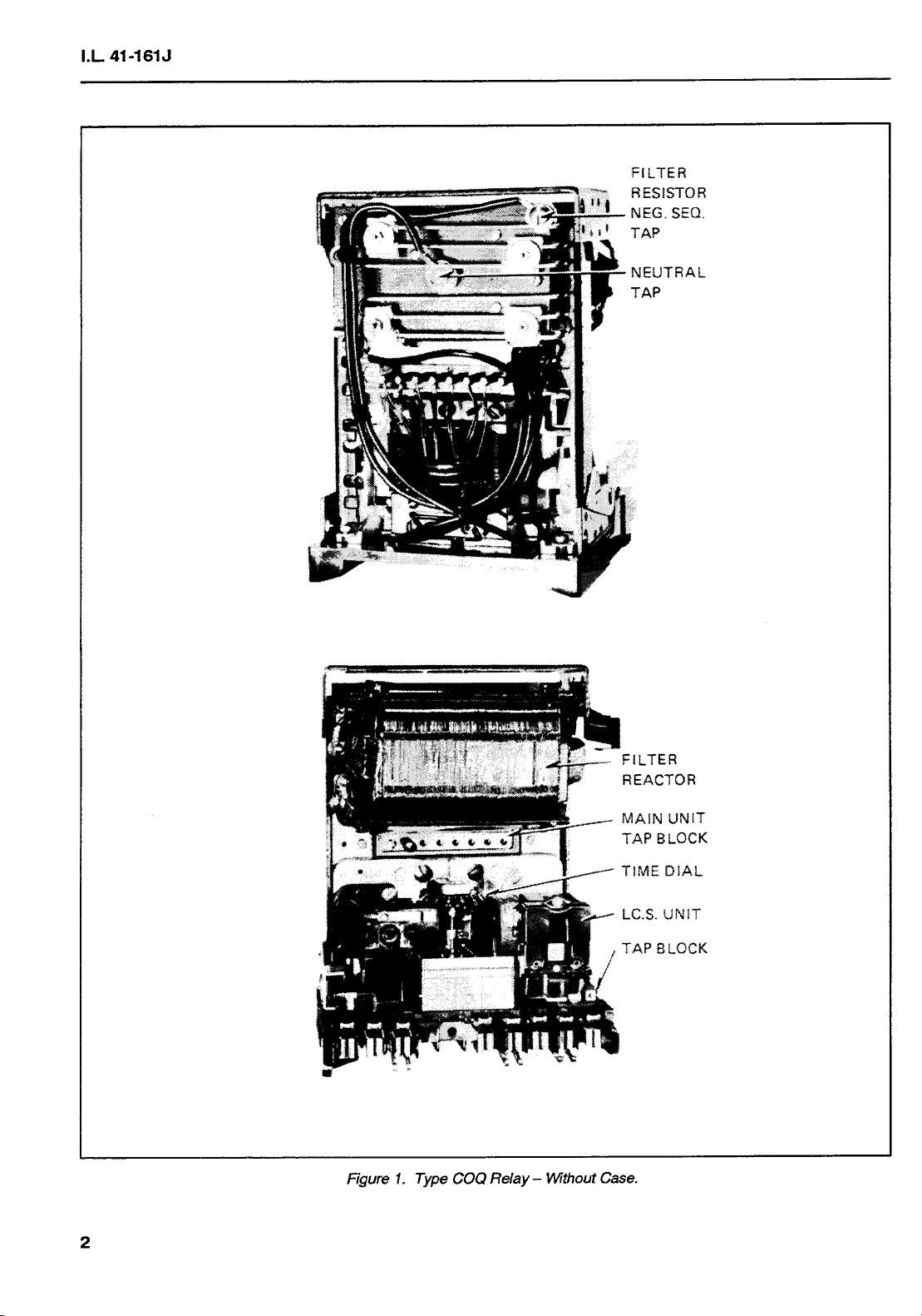
Page 2
Page 3

I.L. 41-161J
TABLE 1
Typical Overcurrent Unit Burden And Thermal Rating
Input Continuous One Second Watts at Volt Amps Circuit Impedance
Condition Phase Rating Amps Rating Amps 5 Amps At 5 Amps Z ∠θ (R+jX)
Three A 5 100 8.3 8.3 0.33 ∠0° (0.33+j 0.00)
Phase B 5 100 1.3 3.8 0.15 ∠110° (-0.05+j 0.14)
C 5 100 2.9 4.7 0.19 ∠52° (0.11+j 0.15)
PHASE-TO-PHASE FAULT CONDITION
Phase A-B 5 100 6.1 6.5 0.26 ∠−161.7° (-0.24-j 0.08)
To B-C 5 100 3.4 8.0 0.32 ∠65° (0.13+j 0.29)
Phase C-A 5 100 10.2 11.5 0.46 ∠−152° (-0.41-j 0.22)
PHASE-TO-NEUTRAL FAULT CONDITION
Phase A-N 5 100 5.1 5.2 0.21 ∠8.70° (0.20+j 0.03)
To B-N 5 100 3.5 3.8 0.51 ∠24.3° (0.14+j 0.06)
Neutral C-N 5 100 4.8 5.5 0.22 ∠29.0° (0.19+j 0.11)
setting of “4” the relay will close its contacts in 30
seconds with the above tap currents applied to the
relay.
As shown by the curves of Figure 5, the relay’s characteristic is defined by a generator characteristic
I22T = K. The relay characteristic is such that it coincides with the generator characteristic at 1 per unit
negative sequence current but at higher values of
negative sequence current, the relay characteristic is
substantially parallel and slightly less than the generator characteristic. In this manner, a suitable margin
of safety is obtained between the two characteristics.
Figure 5 defines the relay characteristics for two generators – one with a permissible constant of “30” and
the other with a constant of “90”. The time dial settings for these constants are “4” and “11” respectively. Similar protection for other generators with
I22T constants between “30” and “90” is obtained by
settings of the time dial. Figure 4 shows the necessary time dial settings for various I22T constants. By
referring to this figure, the time dial can be set so the
relay protects different generators whose I22T constants range from “30” to “90”.
contact spacing. For this figure a tap setting of 3 is
used with a machine full load current of 4.
Typical time-current curves of the relay are shown in
Figure 7. Minimum pickup is approximately 0.6 of the
tap value current. See Table 1 for burdens and terminal ratings.
3.2. Trip Circuit
The main contacts will safely close 30 amperes at
250 volts dc and the seal-in contacts of the indicating
contactor switch will safely carry this current long
enough to trip a circuit breaker.
The indicating contactor switch has two taps that provide a pickup setting of 0.2 or 2 amperes. To change
taps requires connecting the lead located in front of
the tap block to the desired settings by means of a
screw connection.
3.3. Indicating Contactor Switch (ICS)
0.2 ampere tap 6.5 ohms dc resistance
2.0 ampere tap 0.15 ohms dc resistance
4. SETTING CALCULATIONS
Figure 6 demonstrates the use of a tap setting lower
than the full load current of the machine to accommodate I22Tlimits from 5 to 10 while still providing wide
Determine from the machine manufacturer the permissible I22T constant. From Figure 4, find the
required time dial setting.
3
Page 4

Page 5

I.L. 41-161J
5.1. Overcurrent Unit
Insert the tap screw in the appropriate tap determined under Section 4 “Setting Calculations”.
Adjust the time dial setting to the value determined
under Section 4 “Setting Calculations”.
5.2. Indicating Contactor Switch (ICS)
Select the 0.2 or the 2.0 ampere tap setting depending upon the type of device being operated by the
relay. This selection is made by connecting the lead
located in front of the tap block to the desired tap.
6. INSTALLATION
The relays should be mounted on switchboard panels or their equivalent in a location free from dirt,
moisture, excessive vibration, and heat. Mount the
relay vertically by means of the four mounting holes
on the flange for semi-flush mounting or by means of
the rear mounting stud or studs for projection mounting. Either a mounting stud or the mounting screws
may be utilized for grounding the relay. The electrical
connections may be made directly to the terminals by
means of screws for steel panel mounting or to the
terminal studs furnished with the relay for thick panel
mounting. The terminal studs may be easily removed
or inserted by locking two nuts on the stud and then
turning the proper nut with a wrench.
For detailed FT case information refer to I.L. 41-076.
7. ADJUSTMENTS AND MAINTENANCE
The proper adjustments to insure correct operation of
this relay have been made at the factory and should
not require readjustment after receipt by the customer. If the adjustments have been changed or the
relay taken apart for repairs, the instructions below
should be followed.
7.1. Acceptance Tests
The following tests are recommended when the relay
is received from the factory. If the relay does not perform as specified below, the relay either is not calibrated or it contains a defect.
Apply approximately 5 amperes, 3 phase positive
sequences current on 3 amp tap and see that relay
does not operate.
Set relay at #11 time dial and jumper terminals 2, 6
and 8. Set tap 3 and apply 26.0 amperes through ter-
minals 3 and 7. (See Figure 10.) (IA = 26 ∠0° and
IB = 26 ∠180° amperes. Therefore negative
sequence = 15 amps.)
Time of operation with relay in the case should be
3.2 seconds ±8%.
Repeat test with relay on 5.0 tap and 43.3 amperes
through terminals 7 and 9. Time of operation should
be 3.2 seconds ±8%. (Neg. Seq. = 25 amperes.)
7.2. Routine Maintenance
All relays should be inspected periodically and the
time of operation should be checked at such time
intervals as may be dictated by experience to be
suitable to the particular application. Phantom loads
should not be used in testing induction-type relays
because of the resulting distorted current wave
form which produces an error in timing.
All contacts should be cleaned periodically. A contact burnisher S#182A836H01 is recommended for
this purpose. The use of abrasive material for
cleaning contacts is not recommended, because of
the danger of embedding small particles in the face
of the soft silver and thus impairing the contact.
7.2.1. Overcurrent Unit
Apply a single phase current of 8.66 times tap value
(5 per unit negative sequence current) and check
that time of operation is in accordance with Figure
7.
7.2.2. Indicating Contactor Switch (ICS)
Close the main relay contacts and pass sufficient dc
current through the trip circuit to close the contacts
of the ICS. This value of current should not be
greater than the particular ICS tap setting being
used. The indicator target should drop freely.
7.3. Calibration
If the factory calibration has been disturbed, the following procedure should be followed to calibrate
the relay.
7.3.1. Filter
To adjust the filter resistor tap for no response to
positive-sequence current, remove relay from case
and proceed as follows:
a. Jumper switch jaws 2 and 6.
b. Remove overcurrent unit tap screw.
5
Page 6

I.L. 41-161J
c. Pass 10 amperes into switch jaw 3 and out
switch jaw 7.
d. With a 0-15 volt, Rectox type voltmeter, measure
and record voltage between switch jaw 3 and the
tap plate.
e. Now measure the voltage across the resistor.
Adjust top filter resistor position until this voltage
is 1.73 times the reading from (d) above. For
relays wired per Figure 2 connect the voltmeter
to switch jaw 3 and to the top filter resistor screw
connection (see Figure 1). For relays wired per
Figure 3 connect voltmeter across switch jaws 2
and 3.
To eliminate zero sequence response (relays wired
per Figure 2 only), remove tap screw, and connect
per Figure 10: Apply IX = 5 amperes; IY = 10
amperes. Measure voltage from terminal 3 to top
filter resistor screw connection (see Figure 1). Adjust
the neutral filter resistor tap until measured voltage is
zero.
7.3.2. Overcurrent Unit
Turn time dial until stationary contact is deflected
against the backstop. Adjust, if necessary, so that “0”
mark on time dial coincides with index. Then with
time dial at “0” wind up spring until about 5-1/2 convolutions show. From this preliminary setting, and
using 3 tap and time dial setting of “11”, adjust the
permanent magnet until the relay operates in 8.2
seconds with 15.6 amperes single phase or 3 per
unit through terminals 3 and 7 per Figure 10. This
adjustment is made by means of the damping magnet screw.
Next adjust the spring tension until the relay will
close contacts in 90 seconds with 5.2 amperes single
phase (which is tap value or one per unit negative
sequence current) applied through terminals 3 and 7.
This adjustment is made by means of the spiral
spring adjuster. All spring convolutions must be free.
8. RENEWAL PARTS
Repair work can be done most satisfactorily at the
factory. However, interchangeable parts can be furnished to the customers who are equipped for doing
repair work. When ordering parts, always give the
complete nameplate data.
6
Page 7

Page 8

Page 9

Page 10

Page 11

Page 12

 Loading...