

Page 1
—
ABB MEASUREMENT & ANALYTICS | OPERATING INSTRUCTION
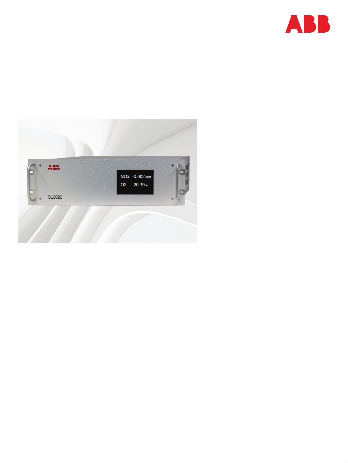
CL3020
CLD NOx analyzer
Measurement made easy
Page 2

2
CL3020 OPERATING INSTRUCTION | OI/CL3020-EN REV. A
Table of Contents
Important precautions .............................................................................................. 5
Use dry, oil-free instrument air only ................................................................. 5
Safety notice......................................................................................................... 5
Model CL3020 specifications ................................................................................... 6
Performance specifications ............................................................................... 6
Features ................................................................................................................ 6
Mechanical specifications .................................................................................. 7
Overview ...................................................................................................................... 8
Measurement configurations ............................................................................ 8
Theory of operation ................................................................................................... 9
Chemiluminescence measurement of NO
Zirconium oxide measurement of O
Pneumatic design .............................................................................................. 10
Analyzer setup and quick start procedure........................................................... 13
Connect the analyzer ......................................................................................... 13
...................................................... 9
x
............................................................... 9
2
Apply power to the analyzer and check diagnostics ................................... 14
Set analog outputs of the analyzer ................................................................ 15
Calibrate the analyzer ....................................................................................... 16
Display screens and details of operation ............................................................ 17
Home screen, warnings, and alarms .............................................................. 17
Calibration menu ............................................................................................... 18
Diagnostic screen .............................................................................................. 19
Trend screen ....................................................................................................... 20
Config screen ..................................................................................................... 20
Analog output scaling screen .......................................................................... 21
Analog output trim screen ............................................................................... 22
IP address screen ............................................................................................... 23
QR code ............................................................................................................... 23
About screen ...................................................................................................... 24
Alarm screen ....................................................................................................... 24
Config alarms screen ........................................................................................ 25
Troubleshooting ...................................................................................................... 26
Diagnostics and operating parameters ........................................................ 26
Warnings and alarms .................................................................................. 26
Sample and ozone flow .............................................................................. 26
Converter temperature .............................................................................. 27
Page 3

CL3020 OPERATING INSTRUCTION | OI/CL3020-EN REV. A
3
Gas concentration readings ...................................................................... 27
System checks .................................................................................................... 27
Electrical connections and fuse ................................................................ 27
Leak checking ............................................................................................... 28
Component information .................................................................................. 28
Oxygen sensor module ............................................................................... 28
Ozonator ....................................................................................................... 28
reaction cell .......................................................................................... 28
NO
x
Converter ...................................................................................................... 29
Main board .................................................................................................... 29
Digital communications ......................................................................................... 30
Setting the IP address ...................................................................................... 30
Modbus over TCP/IP ......................................................................................... 30
Analyzer fault register ................................................................................ 30
Remote operation via VNC ............................................................................... 32
Spare parts ................................................................................................................ 33
List of Figures
Figure 1 Functional pneumatics diagram ........................................................... 12
Figure 2 Home screen............................................................................................. 17
Figure 3 Home screen showing active alarm ..................................................... 17
Figure 4 Home screen showing furnace and ozonator warnings ................... 18
Figure 5 Home screen showing main menu choices ......................................... 18
Figure 6 Calibration menu, for NOx1 gas ............................................................ 19
Figure 7 Numeric entry of calibration bottle value using pop-up keypad ..... 19
Figure 8 Diagnostic screen .................................................................................... 20
Figure 9 Trend screen ............................................................................................. 20
Figure 10 Config screen: Sub-screens for further configuration .................... 21
Figure 11 Analog output scaling screen .............................................................. 22
Figure 12 Analog output trim screen ................................................................... 22
Figure 13 IP address screen ................................................................................... 23
Figure 14 QR code snapshot screen .................................................................... 23
Figure 15 About screen .......................................................................................... 24
Figure 16 Alarm screen, with one alarm cleared and two others active ........ 24
Figure 17 Config alarm screen .............................................................................. 25
Page 4

4
CL3020 OPERATING INSTRUCTION | OI/CL3020-EN REV. A
List of Tables
Table 1 I/O Analog output pin assignments (typical) ....................................... 14
Table 2 Expected flows and temperatures during normal analyzer
Table 3 Analyzer fault register bit assignments ................................................ 31
Table 4 Modbus register map ............................................................................... 31
Table 5 Analyzer spare parts list........................................................................... 33
operation .................................................................................................... 15
Page 5

CL3020 OPERATING INSTRUCTION | OI/CL3020-EN REV. A
5
Important precautions
Use dry, oil-free instrument air only
Caution: This instrument will be damaged if used with in-
strument air that is not completely dry and oilfree. Ensure instrument air has −40 °C dew point
and has been filtered to remove all oil and particulates.
Safety notice
This instrument operates from potentially lethal line voltage. In addition,
some internal components operate at high temperature and can cause serious burns. Observe all precautions when using this device, and particularly
be sure that all devices connected to the instrument are safely wired and
properly grounded. Always disconnect power to the instrument before
opening the enclosure or servicing.
Caution: The analyzer should not be operated without the
cover in place and the cooling fan fully operational.
The exterior surface of the converter furnace and
tubes will rise to nearly 80 °C if operated without
the cover in place. Serious burns can result if the
proper precautions are not taken.
Page 6

6
CL3020 OPERATING INSTRUCTION | OI/CL3020-EN REV. A
Model CL3020 specifications
Performance specifications
NOx O2
Measurement technology Chemiluminescence using
all solid-state detection
Measurement range 0 to 1000 ppm 0 to 25 % O2
Full scale range Continuously adjustable
from 5 to 1000 ppm
Zero noise < 0.04 PPM < 0.02 % O2
Zero calibration drift Better than ± 0.1 PPM Better than ± 0.1 % O2
Span noise < 0.25% of reading < 0.02 %O2
Span calibration drift Better than ± 1% of reading Better than ± 0.1 % O2
Linearity error < 2% of high calibration
value across range from
zero to full scale
Response time T95 < 10 seconds T95 < 10 seconds
NO2 converter efficiency > 95%
Amperometric Zirconium
oxide cell
Continuously adjustable
from 5 to 25 % O
< 1% of high calibration gas
1
value across range from
zero to full scale1
2
Features
• Touch-screen interface: All diagnostics and controls are accessible
through an advanced, full-color 5” touch screen interface.
• One-touch calibration: Once target gas values (e.g. bottle concentra-
tions) have been entered, span and zero responses may be captured,
and hence the analyzer calibrated, at the touch of the screen.
• Trend-screen: Gas concentrations are plotted in a chart-recorder style
trend with user settable scales for in-depth data analysis at a glance.
• Diagnostics and alarms: Critical component temperatures and gas flows
are measured within the analyzer and reported on the diagnostic screen.
Target values and alarmable deviations are user-settable. These alarms
are displayed on the home screen, as well as warning messages for internal communication errors or if the converter or ozonator has been disabled.
• Analog outputs: Each measurement, including dual ranges for NO
output as either 4-20mA or 0-10V (user selectable). Analog outputs can
be forced to low (4mA/0V) or high (20mA/10V) for troubleshooting. Further, the gain and offset of these analog outputs may be trimmed within
, is
x
1
Provided the calibration value is 80 to 100% of the full scale.
Page 7

CL3020 OPERATING INSTRUCTION | OI/CL3020-EN REV. A
7
approximately +/-5% of full scale to compensate for offsets or other issues with an external the data acquisition system, independent of analyzer calibration.
• QR code (2D barcode): Analyzer configuration and operating parame-
ters, including calibration settings, can be sent via any mobile device
that has a QR code / barcode scanning app for ease in remote troubleshooting and support.
• Digital communications: MODBUS over TCP/IP included, allowing access
to gas concentrations, diagnostics, alarms, and other instrument parameters. The analyzer is also equipped with a VNC server that allows full remote operation from any device with a VNC viewer connected to the network. Using a locally connected PC or mobile device, factory personnel
may remotely inspect and diagnose analyzer problems as if they were
standing in front of the analyzer.
Mechanical specifications
• EIA 19-inch rack mount enclosure, 11 in. deep, 3 rack units tall
(5.25 inches).
• Weight: 24 lbs.
• Power: 120VAC, 4 Amps max.
• Sample flow rate: Requires approximately 0.1 SLPM at atmospheric pres-
sure (e.g. from a vented sample manifold) per NO
measurement channel
x
• Instrument air: Requires approximately 0.2 SLPM dry, instrument-quality,
oil-free air at atmospheric pressure (e.g. from a vented manifold), per
NOx measurement channel
Page 8
8
CL3020 OPERATING INSTRUCTION | OI/CL3020-EN REV. A
Overview
The Model CL3020 CLD NOx analyzer is designed specifically for use in low-
CEMS applications. NOx and NO (if dual-channel) are measured using
NO
x
chemiluminescence and a molybdenum-based NO
converter for total NOx.
2
The Model CL3020 meets or exceeds 40CFR60 and 40CFR75 demands for
relative accuracy, linearity, and calibration drift in low and ultra-low NO
x
gas-fired turbine applications.
Caution: The CL3020 is designed to analyze a clean, dry
sample, as is typical of a conventional extractive
CEMS. The sample dew point should be less than 5
C, and without any appreciable particulates or
other condensable or reactive gases. As with all
NOx analyzers, care should be taken in SCR applications to scrub any residual ammonia from the
sample to avoid contamination of internal components.
Measurement configurations
The Model CL3020 has several different configurations:
1. Dual-ranging NO
measured using a molybdenum-based converter to convert any NO
the gas stream to NO
able, e.g full scales of. 100 PPM and 25 PPM, in addition to a single range
output for O
2. Dual NO
(speciating), with or without O2. In this configuration, two inde-
x
pendent chemiluminescence cells are used to simultaneously measure
one converted stream (total NO
difference of these two is reported as NO
be used with an external NH
one channel, total NO
. A variety of analog output options are available in this configura-
NH
3
tion.
3. Enhanced performance for low range NO
scales less than 200 PPM, greater sensitivity may be achieved with modified flows. Flows given in this manual are for standard configuration;
consult factory for more information about flows in this configuration.
, with or without O2. In this configuration, total NOx is
x
. Two separately calibratable NOx ranges are avail-
x
.
2
) and one unconverted stream (NO). The
x
. This configuration may also
2
converter to measure total NOx plus NH3 on
3
on the other channel, with the difference being
x
, with or without O2. For full
x
2
in
Page 9

CL3020 OPERATING INSTRUCTION | OI/CL3020-EN REV. A
9
Theory of operation
The Model CL3020 CLD NOx analyzer uses chemiluminescence as the fundamental detection mechanism for NO
metric) zirconium oxide cell for the O
these mechanisms and their implementation in the analyzer are given below.
Chemiluminescence measurement of NOx
Chemiluminescence is defined as a chemical reaction that gives off light. Nitric oxide (NO) emits infrared light when it reacts with ozone (O
. By introducing a sample containing NO into a reaction cell and mixing
NO
2
it with ozone, one can measure the amount of light emitted by the ensuing
reaction and can infer the amount of nitric oxide present in the original
sample.
It is important to note that only NO is the only species directly measured.
, defined as the sum of NO and NO2 in a sample, is measured by first
NO
x
converting any NO
lybdenum-based converter. If so equipped, NO only is measured in a second
chemiluminescence cell from a sample that does not visit the converter.
measurement and a pumped (ampero-
x
measurement. A brief description of
2
) to form
3
to NO before it enters the measurement cell using a mo-
2
Zirconium oxide measurement of O2
The oxygen measurement makes use of the fact that zirconium oxide conducts oxygen ions when heated above approximately 600 °C. Platinum electrodes on the interior and exterior of a zirconium oxide tube provide a catalytic surface for the exchange of oxygen molecules and oxygen ions. As molecules encounter the platinum electrodes, they become ionized and are
transported through the body of the zirconium oxide. This charge transport
ultimately establishes an electric potential across the electrodes that is proportional to the log of the ratio of oxygen concentrations on each side of
the oxide (The Nernst Equation). Thus, if a reference gas (usually instrument
air at 20.9 % O
ple gas flowing across the outer electrode can be determined. In a conventional zirconium-oxide oxygen analyzer, this voltage is exponentiated to determine the concentration.
In the Model CL3020, a second zirconium-oxide cell is ganged together to
pump oxygen into the first cell, which is maintained at a constant voltage.
The amount of oxygen needed to maintain the primary cell at the operating
point is a more sensitive measurement of sample concentration, and allows
for measurement at zero oxygen. This pump signal is carefully measured
and related back to the sample concentration.
) flows across the inner electrode, the concentration of sam-
2
Page 10

10
CL3020 OPERATING INSTRUCTION | OI/CL3020-EN REV. A
Pneumatic design
Although the chemiluminescence technique is extraordinarily sensitive, specific to NO
pressures, flows, cell geometry, etc. that must be carefully engineered to
produce a properly functioning analyzer. The pneumatic design of the Model
CL3020 is shown in figure 1; the flow scheme is substantially different than
other gas analyzers. To properly operate and service the analyzer, it is important that the flow scheme be well-understood.
Starting on the upper left side of the diagram, instrument air is drawn into
the analyzer from a manifold vented to atmospheric pressure. Excess air
flow should be available at this manifold to ensure integrity of instrument
air to the analyzer. It is important that the air be free of oil and particulates.
Ozone for the chemiluminescence reaction is produced in the ozonator, and
is drawn into the cell where it mixes with the sample stream as described
earlier. A flow-control orifice is embedded in the fitting on the ozone inlet(s)
of the reaction cell(s), and the instrument vacuum pulls the proper flow
through the ozonator.
Two sample channels, if so equipped, may be present on the analyzer. Excess sample flow should be available to each to ensure good sample integrity to the analyzer. A sample pump configured to deliver 1 SLPM under
slight positive pressure to a 1/4" Swagelok
with a vent tube at least three feet long on each branch is an ideal connection.
, and inherently linear, there are many subtle effects involving
x
TM
tee connected to the analyzer,
Note: Under no circumstances should the sample inputs or ozone
feed air be pressurized.
For the total NO
where any NO
channel, the sample first flows through the converter
x
is converted to NO, while any NO present is unaltered. The
2
furnace temperature is displayed on the front panel of the analyzer. Next,
this sample flows though the oxygen sensor (if so equipped), and then
through the sample flow meter. This flow rate should approximately
70 SCCM. The sample then flows on to the reaction cell where it mixes with
the ozone stream and the NO
measurement is performed. The reaction cell
x
is kept at 40 °C.
The exhaust port of the reaction cell contains a critical flow orifice, which
when backed by a sufficiently strong vacuum, controls the
total flow
drawn
through the analyzer. Exhaust from the cell is routed through the high temperature furnace to destroy all the ozone in the exhaust stream to preserve
the integrity of downstream components. Unlike carbon filters or other de-
Page 11

CL3020 OPERATING INSTRUCTION | OI/CL3020-EN REV. A
11
signs, this ozone destruction technique is very safe and effective. No measurable ozone is left in the exhaust. The analyzer is normally configured for an
external pump to provide critical vacuum to pull the exhaust from the reaction cell. The flow through the analyzer is independent of this vacuum, provided it is low enough to meet the conditions for critical flow. The pressure
on the downstream side of the critical flow orifice (measured under conditions of full analyzer flow) should be no more than 30% of atmospheric
pressure.
If equipped, a second sample channel is present which does not flow
through the converter, therefore measuring only NO. The difference between these two channels represents the NO
sample, or any such other speciation (e.g. NH
concentration in the original
2
) depending upon external
3
system configuration.
Page 12

12
CL3020 OPERATING INSTRUCTION | OI/CL3020-EN REV. A
N
O2
Conv
ert
er
F
urnace
Air Inlet
1/4“ Swage
lo
k
1 slpm, max
dry, oi
l-
f
re
e
V
ac
uu
m
must be less
than 300 Torr
at 1.2 slpm
NOx/NO2
I
nl
et
Oz
one
F
low
Meter
Sam
ple orif
ice
f
itt
ing
Vent to atmosphere
(vent tube should be
at least 3 feet lon
g t
o
preven
t d
if
f
us
i
on
)
An
alyzer Enclosure
Samp
le 1
Flow
Meter
O
xyg
en
S
ensor
Ex
aus
t orifice
f
itti
ng
Ozone orifice
fitting
Ozone
Generat
or
Sample 2
Flow
Meter
NOx
cell
(sam
ple
2)
Sample or
ifi
ce
fitting
E
xau
st or
ifice
fi
ttin
g
Ozon
e or
ifi
ce
f
itt
ing
Vent to
at
mo
s
ph
er
e
(v
en
t
tu
b
e s
ho
u
ld
be
a
t l
ea
s
t 3
fe
e
t l
on
g
to
p
r
ev
e
nt
di
f
fu
si
o
n)
P
r
ep
ar
e
d s
a
mp
le from
s
am
pl
e conditioning
system; .25 to 1 slpm,
slightly above atm
p
re
s
su
r
e,
dr
y to less
than 1% water content
P
re
p
ar
ed
s
am
p
le
fr
o
m
s
am
p
le
co
n
di
ti
o
ni
ng
s
ys
te
m
; .
2
5 to 1 slpm,
slightly above atm
p
r
es
s
ur
e,
d
ry
to
l
es
s
t
h
an
1%
w
at
er
c
ontent
Vent to
atmosphere
Exhaust
Outlet
NO
I
nl
et
Instrument
Ai
r I
n
le
t
NOx c
ell
(sample 1)
O
p
ti
on
a
l 2
nd
N
O c
h
an
ne
l
Figure 1 Functional pneumatics diagram
Page 13

CL3020 OPERATING INSTRUCTION | OI/CL3020-EN REV. A
13
Analyzer setup and quick start procedure
For experienced users already acquainted with gas monitoring techniques
and equipment, the following is a summary of installation and startup steps
for a typical CEMS installation; consult factory for other applications. Analyzer menus and operation are described in more detail in the next section
of the manual. To ensure the quickest and most reliable startup, please fol-
low the five steps below in the order shown.
Connect the analyzer
1. Connect instrument air and sample to inlets via 1/4” SwagelokTM fittings.
a. Instrument air: 1 SLPM of dry, oil-free air, vented to ambient condi-
tions. The instrument draws approximately 0.2 SLPM of air per
NO
channel, and a sufficient excess should be supplied to the an-
x
alyzer to ensure the analyzer only pulls instrument air, not ambient
air, from the vented connection (see figure 1).
b. Sample #1 (NO
): 0.2 SLPM of sample from a sample manifold
x
vented to atmospheric pressure. The instrument draws approximately 60 SCCM of sample per NO
channel, and a sufficient ex-
x
cess should be supplied to the analyzer to ensure the analyzer only
pulls sample gas, not ambient air from the vented connection (see
figure 1).
c. Sample #2 (NO), if equipped: 0.2 SLPM of sample from a sample
manifold vented to atmospheric pressure. The instrument draws
approximately 70 SCCM of sample per NO
channel, and a suffi-
x
cient excess should be supplied to the analyzer to ensure the analyzer only pulls sample gas, not ambient air from the vented connection (see figure 1)
2. Connect 1/4” diameter exhaust line (to pump or eductor) to 1/4”
Swagelok™ exhaust port. The vacuum source should be able of maintain an absolute pressure of less than 200 Torr at 1 SLPM flow. For example, a Thomas/Gardner model 2688VE44 mechanical pump or AirVac Engineering AVR-038H air driven eductor.
3. Connect analog output signals via 8-pin Phoenix Contact connector
(provided) per the pin assignments listed in Table 1, and/or Ethernet
connection if using digital communications.
Warning: This instrument is designed for use with 120V AC
input power only. Serious equipment damage
and/or injury will occur if it is connected to improper power.
Page 14

14
CL3020 OPERATING INSTRUCTION | OI/CL3020-EN REV. A
Analog Outputs: The CL3020 analyzer has four analog outputs, assignable
to various measurements, depending upon configuration. Below are analog
output assignments typical of a dual-range non-speciating NO
analyzer.
x-O2
Refer to analog output section of this manual for more information.
NOx output (primary range):
4-20 mA or 0-10V 0 to full-scale ppm
NOx output (secondary range):
4-20 mA or 0-10V 0 to full-scale ppm
O2 output:
4-20 mA or 0-10V 0 to full-scale % O2
Reserved Pin 7: low
Pin 1: low
Pin 2: high
Pin 3: low
Pin 4: high
Pin 5: low
Pin 6: high
Pin 8: high
Table 1 I/O Analog output pin assignments (typical)
Apply power to the analyzer and check diagnostics
Caution: The analyzer should not be operated without the
cover in place. The exterior surface of the converter furnace and tubes will rise to nearly 80°C if
operated without the cover in place. Serious burns
can result if the proper precautions are not taken.
1. Apply power by connecting the instrument power cord (provided).
Verify that the fan is operating by feeling for air flow at the back of
the instrument. If inadequate flow is suspected, shut down power.
Caution: The analyzer should not be operated without the
cover in place and the cooling fan fully functional.
Care should be taken to avoid blocking the air
vents in the side panel. Standard EIA rack mounting should provide enough space for adequate
cooling.
2. After approximately one minute the touchscreen will complete its
startup cycle and be at the home screen. Navigate to the diagnostic
screen and verify the following as summarized in Table 2:
Page 15

CL3020 OPERATING INSTRUCTION | OI/CL3020-EN REV. A
15
a. Verify that the sample-flow (on the diagnostic screen) indicates
approximately 70 SCCM per channel and the ozone-flow (diagnostic screen) indicates approximately 230 SCCM for single channel
or 460 SCCM for dual channel configuration. If flows are not
NO
x
correct, check pneumatic connections and external system components (e.g. pump).
b. Verify the furnace temperature is rising. The furnace temperature
should reach 400°C in about 30 minutes.
c. Verify the ozonator temperature is rising. The ozonator tempera-
ture should reach 40°C in about 15 minutes. It may be necessary to
adjust the ozonator setpoint temperature for operation in unusually cool or warm environments. The operating temperature is not
important, it is only necessary that the ozonator temperature remains constant.
d. Verify the NO
reaction cell(s) temperatures is rising. The NOx cell
x
temperature(s) should reach 40°C in about 15 minutes.
Parameter Value
Sample flow 70 SCCM
Ozone flow 230 SCCM single NOx, 460 SCCM dual NOx
Converter temperature 400 oC
Ozonator temperature 50 °C (user settable)
NOx cell #1 temperature 40 °C
NOx cell #2 temperature (if equipped) 40 °C
Table 2 Expected flows and temperatures during normal analyzer operation
Set analog outputs of the analyzer
From the analog output screen located within the Config menu, set full
scale to desired values for each output channel, per configuration. Refer to
analog output section of this manual for more information.
Page 16

16
CL3020 OPERATING INSTRUCTION | OI/CL3020-EN REV. A
Calibrate the analyzer
After installation and temperatures have reached their setpoints above, the
and O2 channels can each be calibrated via the following procedure:
NO
x
1. Low calibration:
a. Flow low calibration gas through the sample handling system and
analyzer. Dry nitrogen, EPA protocol zero gas, or well-scrubbed instrument air is recommended as a low calibration gas for NO
may be zeroed on NO span gas.
O
2
b. Wait approximately two minutes or until reading settles. It may be
helpful to monitor the trend screen to evaluate when the reading
has reached final value.
c. Enter the value of the low calibration gas, typically 0.
d. Press “Low Capture” soft button on the calibration screen.
2. High calibration:
a. Flow high calibration gas through the sample handling system and
analyzer.
.
x
b. Wait approximately two minutes or until reading settles. It may be
helpful to monitor the trend screen to evaluate when the reading
has reached final value.
c. Enter the value of the high calibration gas, typically from the re-
ported bottle value from the calibration gas supplier.
d. Press “High Capture” soft button on the calibration screen.
Page 17

CL3020 OPERATING INSTRUCTION | OI/CL3020-EN REV. A
17
Display screens and details of operation
Home screen, warnings, and alarms
The analyzer home screen analyzer is shown in Figure 2 below. In this view,
only gas concentrations are displayed. Gas concentrations displayed will
vary by configuration.
Figure 2 Home screen
If active alarms are present (any diagnostic variable out of range, see section on Alarm screen), a red triangle with an exclamation point will appear in
the lower right-hand corner of the display as shown in Figure 3. Touching
this icon will bring up the Alarm screen as described later.
Figure 3 Home screen showing active alarm
If there are active warnings, these descriptors will be annunciated in a banner at the bottom of the screen as shown in Figure 4. Possible warnings include:
• Communications error between display and main analyzer board,
warning the display may not be updating thus readings or statuses
may be invalid.
• Ozonator and/or furnace disabled (see Configuration screen)
• Analog outputs forced high or low (see Analog Output Trim screen)
Page 18

18
CL3020 OPERATING INSTRUCTION | OI/CL3020-EN REV. A
Figure 4 Home screen showing furnace and ozonator warnings
Analyzer menus may be accessed by touching the screen anywhere, causing
the menu bar to become available at the bottom of the screen for about five
seconds as shown in Figure 5. When the menu is visible, any of the main
screens (Calibrate, Diagnostics, Trend, Config, of Alarm) may be selected.
Note: The menu bar will appear from any of the main screens by touching
the screen anywhere there is not an active input box or button, enabling to
return to the Home screen from any other main screen.
Figure 5 Home screen showing main menu choices
Calibration menu
Figure 6 shows an example calibration screen, in this case NOx1. Each gas
has its own calibration screen selectable by touching the corresponding rectangle from the column of choices on the right of the screen.
In this screen the raw value displayed corresponds to the percentage of analog input from the sensor. When troubleshooting, the raw value is often
more important to examine than the calculated concentration. This is because the calculated value may be corrupted by erroneous calibration, but
the raw value represents the underlying sensor response. The gain is the calculated correspondence between gas concentration and raw value captured
during calibration, as described below.
Page 19

CL3020 OPERATING INSTRUCTION | OI/CL3020-EN REV. A
19
The analyzer is calibrated by assigning sensor responses to gas concentrations. Any two points may be used for calibration, but typically zero and
span are chosen. Bottle values for calibration may be entered by selecting
the appropriate field and entering numeric values form the pop-up touch
keypad, as shown in Figure 7. This same keypad is available for all numeric
entries throughout the interface.
Stored raw values corresponding to gas bottle values (or known process values) may be “captured” by pressing the high or low capture buttons when
high or low concentration gas, respectively, is flowed to the analyzer. These
response values may be entered manually by entering raw values in these
fields using a numeric pop-up touch keypad.
Figure 6 Calibration menu, for NOx1 gas
Figure 7 Numeric entry of calibration bottle value using pop-up keypad
Diagnostic screen
Table 2 shows typical values for expected flows and temperatures during
normal operation. These diagnostics are displayed in the main diagnostic
screen, and shown in Figure 8. Refer to the Alarms screen for setting limits
on these parameters, and the troubleshooting section of this manual of if
these values are out of range.
Page 20

20
CL3020 OPERATING INSTRUCTION | OI/CL3020-EN REV. A
The 32-bit Fault Register is defined in more detail in the digital communications section. Bit 0 is on the far right, bit 15 is on the far left. Bits are one
(TRUE) if in alarm condition, zero if not alarmed.
Figure 8 Diagnostic screen
Trend screen
The trend screen is shown in Figure 9. Note that the scale for Oxygen (on
the left) and NO
and bottom numbers and rescaling with the pop-up keypad. The trend
screen displays ten minutes of data, refreshing once a second.
reading(s) on the right is adjustable by selecting the top
x
Figure 9 Trend screen
Config screen
The configuration screen is shown in Figure 10.
Furnace power and ozonator output may be toggled by tapping the appropriate buttons. Ozonator temperature will be maintained if disabled, only
the ozonator discharge itself is disabled. Warnings messages will be displayed on other screens when either of these components is disabled.
Page 21

CL3020 OPERATING INSTRUCTION | OI/CL3020-EN REV. A
21
The furnace temperature setpoint may be adjusted from this screen. During
steady state operation at room temperature, the power duty cycle should
be approximately 35%.
Averaging time for signals may be set to any value between 3 and 60 seconds. 15 seconds is the default,
Sub-screens for Analog outputs, IP address, QRC, and About may be accessed from this screen and are described below.
Figure 10 Config screen: Sub-screens for further configuration
Analog output scaling screen
The analog output screen is shown in Figure 11, in the case of dual-ranging
with O2. Other gas configurations are similar and self-explanatory. Con-
NO
x
centrations corresponding to low and high analog outputs may be set using
the numeric pop-up keypad as shown in Figure 7.
Current (4-20 mA) or voltage (0-10V) output is selectable from the Type
menu box in the upper right-hand corner. Note the voltage output is intended for use only with high impedance (>1000 kOhm) devices.
Actual live outputs are shown for reference
Note the “gear” icon to the left of each channel. Selecting this icon brings up
the Analog output trim screen for each channel, as described below.
Page 22

22
CL3020 OPERATING INSTRUCTION | OI/CL3020-EN REV. A
Figure 11 Analog output scaling screen
Analog output trim screen
Each analog output channel may be trimmed independently from its own
screen, as shown in Figure 12. Under normal operation, the output is in “live”
mode, but it may be forced to either the high or low limits by selecting the
corresponding box. When the output is so forced, the corresponding trim
field is active and may be used to adjust the actual output up or down to
make up for any system discrepancies. In this manner, the analog loops and
any external data acquisition system may be calibrated independent of gas
concentration readings. This may also be used for troubleshooting external
connections.
Note that when any outputs are forced high or low, a warning is displayed
to the user in the warning banner in the lower portion of any main screen.
The “Next” and “Return” buttons allow the user to cycle through other analog channels and/or return to the main analog output screen.
Figure 12 Analog output trim screen
Page 23

CL3020 OPERATING INSTRUCTION | OI/CL3020-EN REV. A
23
IP address screen
The IP address screen is available from the Config screen. Either a static or
dynamic IP address screen may be specified.
Figure 13 IP address screen
QR code
A standard QR code (2D barcode) image, as shown in Figure 14, may be displayed for capture and analysis by any mobile device with barcode scanning
capability. Scanning with a mobile device will provide a text description of
the analyzer configuration, status, and current readings that can be sent to
support personnel for troubleshooting assistance.
Figure 14 QR code snapshot screen
Page 24

24
CL3020 OPERATING INSTRUCTION | OI/CL3020-EN REV. A
About screen
The About screen, as shown in Figure 15, shows the current software versions for the system.
Figure 15 About screen
Alarm screen
The alarm screen is shown in Figure 16, accessible from the home screen by
touching the red triangle. An active, or historical but uncleared, alarm sets
the corresponding bit in the fault register, and causes the red alarm icon to
flash on any main screen. If an alarm condition is still being met (causing the
alarm), the alarm listing will be highlighted red. If the alarm condition is no
longer being met (not alarmed), the text will no longer be highlighted in red,
but still visible in the alarm history. The history can be cleared by tapping
the “Clear” button. Only alarms that are no longer active may be cleared; if
an alarm condition is still occurring it will reactivate and not remain cleared.
To access the sub-menus allowing configuration of each alarm, touch the
Config Alarms button on this screen.
Figure 16 Alarm screen, with one alarm cleared and two others active
Page 25

CL3020 OPERATING INSTRUCTION | OI/CL3020-EN REV. A
25
.
Config alarms screen
Each alarmable temperature and flow is configurable, as shown in Figure 17,
in this case for the furnace temperature. While factory defaults settings
should normally not require modification, allowing these to be configurable
enables the user to operate the analyzer in custom configurations for
unique applications or for testing purposes, while still having meaningful
alarm conditions. A target value and deviation from the target may be set in
the corresponding boxes. Note in the case of a control loop, like furnace
temperature, this is only the target for the alarm, not the control setpoint
temperature
Figure 17 Config alarm screen
Page 26

26
CL3020 OPERATING INSTRUCTION | OI/CL3020-EN REV. A
Troubleshooting
Below is troubleshooting information on the analyzer, as well as information
on many of the sub-assemblies within the unit. Before troubleshooting the
analyzer, read through the diagnostic and operating parameters explanations to help narrow down any problems.
Warning: Potentially lethal line voltage, lethal high voltage
(within the ozone generator), and dangerously hot
tubing and subassemblies are present within the
analyzer. Service within the analyzer should be
performed only by qualified, trained personnel,
and only after the unit has been unplugged and allowed to cool for at least one hour with the cover
off.
Diagnostics and operating parameters
The diagnostics on the analyzer display much instrument status information (see diagnostics screen). From these readings, it is usually possible
to narrow down the source of any problems:
Warnings and alarms
The Home screen of the display will display the presence of any warnings or
alarms. Carefully check this information to troubleshoot any problems, for
example if NO
been left disabled.
Sample and ozone flow
Because these two flow rates are intimately related, it is important to consider them together. Sample flow is the amount of flow drawn through the
sample inlet through the analyzer. Ozone flow is the amount of feed air
pulled through the ozonator.
A critical flow orifice located in the exhaust fitting of the NO
mines the total flow (sample and ozone flow combined). This total flow rate
should be approximately 230 SCCM per channel.
One may determine several things by inspecting the NO
flow meters:
is not responding it may be the case that the ozonator has
x
cell deter-
x
sample and ozone
x
• If the both flows are correct, it is very unlikely that there are pneumatic
problems within the analyzer.
Page 27

CL3020 OPERATING INSTRUCTION | OI/CL3020-EN REV. A
27
• If the both flow are low, there may leaks in the analyzer, the critical flow
exhaust orifice may blocked, the sample inlet may be blocked, the exhaust may be blocked or not vented properly, or the vacuum at the rear of
the analyzer may be inadequate.
• If the ozone flow is too low, the ozone air feed orifice may be blocked,
there may be a leak in the ozone supply tubing, or the compressed air
supply to the instrument may be faulty.
• If the sample flow is too low, the sample orifice may be blocked, there
may be a leak in the sample tubing, or the sample supply to to the instrument may be blocked
• If either or both flows are too high, check for pressurization of sample or
instrument air (inadequate or blocked vents), or other blockages. For example, if the ozone flow is restricted, one indication may be higher than
normal sample flow, and vice versa.
Converter temperature
The converter furnace temperature is maintained at 400 °C. The temperature should not vary by more than two degrees. If it is not at the proper
value, the furnace heater, thermocouple, or relay could be at fault.
Gas concentration readings
The O2 value should be stable to approximately 0.02% (absolute). Instability
or inaccurate readings could be caused by leaks or a faulty O
ule. The NO
reading should be stable to better than 0.25% or reading, or
x
sensor mod-
2
0.02 PPM, whichever is greater. Instability or inaccurate readings could be
caused be leaks, a faulty ozonator, or a faulty NO
sensor or sensor board.
x
System checks
Component failures within the analyzer are relatively uncommon. Most performance or reliability problems are due to improper system connections,
leaks, faulty electrical connections, or improper configuration, in that order.
Before opening the analyzer enclosure, double-check that the external connections and supply of conditioned sample gas, compressed air, and line
voltage are correct. The following may aid in troubleshooting if the analyzer
is not functioning properly and no faults are apparent form the diagnostic
information.
Electrical connections and fuse
Be sure all connectors on the main board are firmly seated and that all wires
within these connectors are firmly attached. There is a fuse holder on the
main power inlet of the analyzer, serviceable from the analyzer back panel.
Page 28

28
CL3020 OPERATING INSTRUCTION | OI/CL3020-EN REV. A
Leak checking
Leaks may cause many non-obvious problems, a leak check is highly recommended when servicing or troubleshooting gas analyzers for any reason.
Leak checking should be done under vacuum, never pressure with the following procedure:
1. Seal the sample and instrument air inlet(s) on the back of the analyzer.
2. Connect a vacuum pump to the exhaust port, with an isolation valve in
between the pump and the analyzer, and a vacuum gauge on the analyzer side of the isolation valve.
3. Open the isolation valve, pump the analyzer down, and record the vac-
uum reading.
4. Close the isolation valve. The isolated analyzer pressure should not in-
crease more than 2 Torr/second.
If leaks are found, check all fittings for tightness, and locate the leak by progressively isolating parts of the analyzer. In general, if a leak is present it will
be very noticeable, not subtle. A slight apparent leak within the ozonator is
acceptable; a metered sweep of the ozonator assembly is designed to minimize stray ozone within the analyzer enclosure.
Component information
Information on service replacement of many of the analyzer components is
given below. Only proceed to investigation of components after thoroughly
checking pneumatic and electrical connections both inside and external to
the analyzer as noted above. “Part-swapping” without clear indication of
component failure is not a recommended troubleshooting or repair technique.
Oxygen sensor module
This is serviced as a unit. If approximately 9VDC is present on pins 1 and 2 of
the five-pin connector, and oxygen readings are unstable, nonlinear, or inaccurate, replace this module. If 9VDC is not present, examine connections.
Ozonator
Lethal voltage is present with the ozonator: Do not attempt to service the
ozone generator, and never open its enclosure or allow tools to come near it
when the analyzer is energized. The ozonator hums audibly when operating,
if power is being supplied to this unit (24VDC) and there is no hum, the
ozonator should be replaced.
NOx reaction cell
The NOx reaction cell has several fittings and the NOx sensor mounted on it.
Page 29

CL3020 OPERATING INSTRUCTION | OI/CL3020-EN REV. A
29
The exhaust fitting on the back of the cell houses the critical flow orifice. It
may be changed by disconnecting the tube leading into the furnace and unscrewing the fitting. The orifice and fitting are replaced as an assembly.
If the readings have dropped, or if the analyzer has been subjected to ammonia, it may be necessary to clean the window on the sensor:
1. Turn off power to the analyzer and remove vacuum from the exhaust port.
2. Remove the two screws holding the detector assembly to the reaction
cell and remove the detector assembly.
3. Wipe off the optical window of the sensor through this port with deion-
ized water or rubbing alcohol to remove any film or deposits. Do not use
harsh solvents or abrasive materials.
4. Reinstall the detector assembly.
5. Energize analyzer, and apply vacuum. Leak check if readings unstable.
Converter
The converter has a cartridge heater and a thermocouple. The heater element and thermocouple connect to the main board near the back of the analyzer. The converter is typically replaced as an assembly, although the thermocouple and heater may be field replaced by experienced service personnel. The heater assembly should be replaced if either side of the heater
shows less than 1 MΩ resistance to the shell or if the heater resistance is not
approximately 70 Ω.
The power control relay for the heater is socketed near the rear of the board
and may require replacement if the converter power supply has been shortcircuited. The molybdenum charge may be replaced, consult factory for details.
Main board
If the main board must be replaced, the analyzer should be de-energized
and all connections removed before attempting to remove the board.
Page 30

30
CL3020 OPERATING INSTRUCTION | OI/CL3020-EN REV. A
Digital communications
The model CL3020 analyzer can act as a MODBUS server (slave) and may
also be operated remotely via any standard PC or mobile VNC viewer. Additionally, a QR-code, i.e. 2D barcode, may be scanned by a mobile device to
capture a complete snapshot of instrument status that can easily be sent to
remote troubleshooting personnel.
Setting the IP address
The IP address for the analyzer is normally set to a static value of 192.168.1.50,
and can be changed by tapping the IP Address button on the Config Screen.
Either a static or dynamically assigned (DHCP) address can be specified.
Modbus over TCP/IP
The CL3020 can serve as a MODBUS slave over TCP/IP. The MODBUS register map is shown in Table 4.
Analyzer fault register
The 32-bit analyzer fault register reflects the alarm status of the analyzer,
whereas any non-zero value represents an alarm condition. The fault register bit assignments are listed in Table 3. The lowest bit (0) is set to true if
any alarm is present allowing for quick reading of a single bit for overall
alarm status. The fault register is also available in float data-type representation of the 32-bit value to allow it to be read along with many other input
registers using a single read command.
Bit Parameter True (1) if
0 Instrument Fault Any alarm
1…5 Reserved
6 O2 Heater Alarm
7 Sample Flow 1 Alarm
8 Sample Flow 2 Alarm
9 Ozonator Flow Alarm
10 NO x 1 Te m p Alarm
11 NOx2 Temp Alarm
12 Ozonator Temp Alarm
13 Furnace Temp Alarm
14 Analyzer Temp Alarm
15 Comms Error Alarm
16…31 Reserved
Modbus server version 1.00100
Page 31

CL3020 OPERATING INSTRUCTION | OI/CL3020-EN REV. A
31
Table 3 Analyzer fault register bit assignments
Parameter Register
Num*
Data
Type
Notes
Modbus Slave Version 30001 Int32
System Board Firmware Version 30003 Int32
Display Software Version 30005 Int32
Status (integer) 30007 Int32
Status (float) 30021 Float Float of (Int32 Status) to allow all float reads
Concentration Gas NOx 1 30023 Float Live concentration in gas-units
Concentration Gas NOx 2 30025 Float Live concentration in gas-units
Concentration Gas O2 30027 Float Live concentration in gas-units
Reserved 30029
Raw Response Gas NOx 1 30031 Float Live signal response in % of available input
Raw Response Gas NOx 2 30033 Float Live signal response in % of available input
Raw Response Gas O2 30035 Float Live signal response in % of available input
Reserved 30037
Temperature Analyzer 30039 Float degrees C
Temperature NOx 1 Cell 30041 Float degrees C
Temperature NOx2 Cell 30043 Float degrees C
Temperature Ozonator 30045 Float degrees C
Temperature Furnace 30047 Float degrees C
Heater Power Furnace 30049 Float Live furnace power in %
Flow Sample 1 30051 Float Live sample 1 flow in cm3
Flow Sample 2 30053 Float Live sample 2 flow in cm3
Flow Ozone 30055 Float Live ozone flow in cm3
Stored Span Response NOx 1 40101 Float Stored response in % of available input
Stored Zero Response NOx 1 40103 Float Stored response in % of available input
Stored Span Response NOx 2 40105 Float Stored response in % of available input
Stored Zero Response NOx 2 40107 Float Stored response in % of available input
Stored Span Response O2 40109 Float Stored response in % of available input
Stored Zero Response O2 40111 Float Stored response in % of available input
Span Bottle Concentration Gas 1 40113 Float Bottle concentration in gas-units
Zero Bottle Concentration Gas 1 40115 Float Bottle concentration in gas-units
Span Bottle Concentration Gas 2 40117 Float Bottle concentration in gas-units
Zero Bottle Concentration Gas 2 40119 Float Bottle concentration in gas-units
Span Bottle Concentration Gas 3 40121 Float Bottle concentration in gas-units
Zero Bottle Concentration Gas 3 40123 Float Bottle concentration in gas-units
Converter Furnace Enabled 1 Bool True (1) enables furnace power
Ozonator Enabled 2 Bool True (1) enables ozonator power
* Register numbers 30xxx are input registers, 40xxx are holding registers,
x are output coils. Modbus server version 1.00100
Table 4 Modbus register map
Page 32

32
CL3020 OPERATING INSTRUCTION | OI/CL3020-EN REV. A
Remote operation via VNC
It is possible to operate the CL3020 remotely by any VNC viewer connected
via TCP/IP. Every display and every action that is available from the analyzer
display is duplicated on the remote device, with a mouse click or screen
touch on the remote device serving as the same input as front screen touch
commands.
Any VNC viewer may be used, once the IP address of the analyzer is known.
The VNC connection password is CL3020 (case sensitive) and cannot be
changed. TCP port 5900 is used for the VNC connection and must not be
blocked by any routers or firewalls between the analyzer and the remote device.
Page 33

CL3020 OPERATING INSTRUCTION | OI/CL3020-EN REV. A
33
Spare parts
Part description Part number Recommended on-site quantity
Exhaust orifice fitting 1000-1020 2
Sample orifice fitting 1000-1030 2
Ozone orifice fitting 1000-1031 2
NOx detector O-ring 1000-1032 2
Fuse 1000-1033 2
Oxygen sensor 1000-1034 1 (if configured)
Ozone generator 1000-1035 Optional
NO2 furnace assembly 1000-1036 None
Furnace media recharge 1000-1037 None
NOx Detector 1000-1038 None
Flowmeter 1000-1039 None
Furnace relay 1000-1040 None
Furnace heater 1000-1041 None
Furnace thermocouple 1000-1042 None
Furnace sample fittings 1000-1043 None
Display 1000-1044 None
Electronics board 1000-1045 None
Fan 1000-1046 None
Sample tubing, 5 ft 1000-1047 None
Exhaust tubing, 2 ft 1000-1048 None
Tubing tee 1000-1049 None
Table 5 Analyzer spare parts list
Page 34

—
ABB Automation GmbH
Measurement & Analytics
Stierstädter Str. 5
60488 Frankfurt am Main
Germany
Fax: +49 69 7930-4566
Mail: cga@de.abb.com
abb.com/analytical
—
We reserve the right to make technical changes or modify the contents of this document
without prior notice. With regard to purchase orders, the agreed particulars shall prevail.
ABB does not accept any responsibility whatsoever for potential errors or possible lack of
information in this document.
We reserve all rights in this document and in the subject matter and illustrations contained
therein. Any reproducti on, disclosure to third parties or utilization of its contents – in w hole
or in parts – is forbidden without prior written consent of ABB.
© ABB 2018
OI/CL3020-EN Rev. A 04.2018
 Loading...