

ABB 2CCS800900R0161, 2CCS800900R0011, 2CCS862001R0804, 2CCS863001R0824, 2CCS862001R0634 User Manual
...Page 1

ABB
Technical Manual
ABB Schweiz AG
8201 Scha ffhausen 1 / 10
Please use also the assembly instruction S800-RSU-H Remote Switching Unit for S800
2CCC413020M0204
Functi onal Descr iption for
S800-RSU-H / S800W-RSU
2CCC413022M0205
SUBJECT TO ALTERATIONS
09.04.2014
Page:
Index
1 Functionality 2
1.1 Operation and control 2
1.2 Environment 2
1.3 Functional Requirement 3
2 External Connections 4
2.1 Operating voltage 4
2.2 Inputs 4
2.3 Outputs 5
2.4 Circuit times 5
2.5 Pin assignment 6
2.5.1 In- and Output Allocation 6
2.5.2 Simplified Diagram of the control 7
3 Timing diagrams 8
3.1 OFF – ON / ON – OFF / ON – ON / OFF - OFF 8
3.2 Power up if contacts are open resp. closed 9
3.3 ON – Trip / Trip – OFF / Trip – ON / Power up - Trip 10
ABB Switzerland Ltd.
Fulachstrasse 15 0
CH-82 01 Schaffhausen
Phone: +41 58 586 41 11
Fax: +41 58 586 42 22
E-mail: administration@ch.abb.com / www.abb.com
Page 2

S800-RSU Technial Manual Page 2 / 10
1 Functionality
1.1 Operation and control
The intention is the fast, secure and energy-awa re moving of the lever of S800 High Performance MC B. Th e controller
interprets the two command inputs ON and OFF. The controller does a switching command when a positive edge at one of
the two command inputs is detected and the signal is for at least 10ms stable. Once the home position is reached after
switching operation, the corresponding feedback signal is activated. Once the home position is reached and the feedback
signal is turned on, a new control command can be initiated.
When the S800 triggers due to overload, short circuit or manual activation, this is registered and issued by activating the
"TRIP".
A "ON" or "OFF" switching command can be triggered directly from the "TRIP" position. When detection a trip movement the
motor moves into OFF-position to secure the contact opening and to prevent a subsequent manually switching of the S800
via lever.
Under normal operation, it is always only one output active. If the motor is in motion, no output is active.
The motor switches powerless after executing the control c ommand. Thus a twist of the spindle to snap the external safety
lock or manual actuation by screwdriver is possible.
If the spindle is moved by more than one rotation from the current positi on, all o utputs are turned on. If the spindle o nly
slightly rotated manually (> 7.5°) for 10 seconds no commands will be accepted. The initialization takes place when a
switching command is detected only. The switching command is executed after initialization. Until the beginning of the
initializati on, all ou tputs are active.
1.2 Environment
Operating Voltage +24 VDC +10 % / -15 %
Cur rent C onsumption 2,5 A
ABB recommends:
ABB switching power supply CP-S 24/5.0
(The power supply needs at least a nominal current rating of 5A.
Furthermore it must be able to cover short spikes above the rated
current rating without decreasing the input voltage under 20V DC)
Load Peaks 8A for 0.1ms at power up
3.5A for 250ms during operation
Standby Current < 50 mA
Ambient operation temperature
Coldness
Dry heat
Dam p heat
Relative humidi ty < 85 % at 45 °C (No bedewing)
Dimensions
Depth
Height
Unit width
Contact trip indicator Yes (ON – TRIP – OFF)
Trip position of actuating lever Yes
Mechanical Fixing Field mountable and wireable on High Performance MCBs S802…,
Up to -25 °C according to IEC 60068-2-1:2007
Up to +70 °C according to IEC 60068-2-2:2007
Up to +55°C by 95% rel. hum. acc. to IEC 60068-2-30:2005
134,2 mm (5,28 in)
100,6 mm (3,96 in)
54 mm (2,13 in)
S803…, S804 via Allen head screw size 3 and mounting bracket.
Required tightening torque 3 Nm
Page 3

S800-RSU Technial Manual Page 3 / 10
Maximum Cable length Power supply: up to 10m with 0.5 mm2(32 feet 9.7 in with AWG20)
Control supply: up to 10m with 0.5 mm2(32 feet 9.7 in with
AWG20)
Guidelines RoHS
Reference standards IEC 60947-2 Annex N
- IEC 61000-4-2
- IEC 61000-4-3
- IEC 61000-4-4
- IEC 61000-4-5
- IEC 61000-4-6
- IEC 61000-4-11
IEC / CISPR 22
EN 61000-6-2
- IEC 61000-4-8
EN 61000-6-4
- IEC / CISPR 16-2-3
- IEC / CISPR 22
EN 61000-4-16 (from 20kHz)
UL489 sections 14, 16
60068-2-1
60068-2-2
60068-2-30
1.3 Functional R equire ment
Maintenance: Maintenance free during lifetime
Maximum number of switching cycles: 10.000 mechanical switching operations if mounted on S800 High
Performance MCB
Manual switch OFF: If manual use is detected (> 7.5°), inputs will be deactivated for 10
seconds. Outputs re main unchanged. If spindle is being turned
more than once, all outputs become active until next command is
accepted. Intuitive manual switch-off via lever is possible.
Manual switch ON: If manual use is detected (> 7.5°), inputs will be deactivated for 10
seconds. Outputs re main unchanged. If spindle is being turned
more than once, all outputs become active until next command is
accepted. Intuitive manual switch-on via lever is not possible.
Mechanical lock:
Referencing by startup
Mechanical fixation by secured lock slider blocking the actuation
spindle independent of its position
By startup the S800-RSU-H / S800W-RSU refers unique
Referencing after voltage interruption
When operating voltage is restored a unique referencing take
place. Regardless of the switching position of the High
Performance MCB S800 the referencing held in the OFF position.
Page 4

S800-RSU Technial Manual Page 4 / 10
2 Extern al Connections
2.1 Operating voltage
We recommen d the u se of a normal commercial power supply with 24 V nominal voltage and nominal current carrying
capacity of 5 A as the power supply for the 4-pole version of S800. During simultaneous control of several S800-RSU-H /
S800W-RSU, the power supply has be configured concerning current carrying capacity.
The power supply must be able to cover short spikes above the nominal current carrying capacity without the input voltage
at the controller dropping below 20 VDC. A power supply with a lower nominal current carrying capacity can be used for the
2 and 3 pole MCB variants. The maximum current is only needed during the switch-on movement. The earths of the power
supply and the digital inputs and outputs are connected to each other.
2.2 Inputs
The inputs are designed for connection to a standard PLC, which switches the positive side of the outputs. The inputs can
be connected directl y via a mechani cal or electronic cont act with the sup ply voltage to t ri gger a cont rol c ommand. An open ,
non-connected input is interpreted as a logic 0.
The masses of the digital inputs and the operating voltage supply are connected internally. The masses of different external
power supplies must also be connected.
The input will be internally debounced with a time constant of about 10 ms. To recognize an operation command, the input
signal has be for at least 10ms logical 0 and then for at least 10 ms logical 1. Thus the software debouncing can be
effectively and detects a level change from logic 0 to logic 1.
Function: command ON, command OFF
Voltage range logic 0 0…4 V
Voltage range logic 1: 10…24 V
t
: ca. 20 ms
min
Input resistance: ca. 93 kΩ
Input current at 24 VDC: ca. 260 µA
Electric filter delay time: 0.5 ms
Overvoltage capability and inverse-polarity protection: ± 27 V
Page 5

S800-RSU Technial Manual Page 5 / 10
2.3 Outputs
The outputs are designed for connection to a standard PLC or the direct switching of small loads.
Function: Feedbacks ON, OFF, TRIP
Voltage range: 12…26.4 VDC
Maximum load: 10 mA
Logic 0 leakage current < 100 µA
Output voltage at 24 VDC, 10 mA > 23 VDC
2.4 Circuit times
Duration of closing operation of S800 contacts from
signal on (OFFàON):
Duration of opening operation of S800 contacts from
signal on (ONàOFF):
Duration of closing operation of S800 contacts from
signal on (TRIPàOFFàON):
Number of switching attempts in case of thermal or
magnetic fault on S800 before lock:
Number of switching attempts when lock slider is in
locked position
Switching force: ca. 120 N
Degr ee of protection: IP20 if mounte d
< 500 ms
< 250 ms
< 1500 ms
15 minutes (± 5 %) lock after three switching attempts without
supply voltage interruption / switching-off
One minute lock after one attempt per minute
Page 6

S800-RSU Technial Manual Page 6 / 10
2.5 Pin assignment
The black Microfit female (e.g. Molex series 43045) is numbered from down right to top left as seen in the pictures below
NOTE:
When connecting the cable please make sure that the individual strands are not exposed to mechanical stress.
2.5.1 In- and Output Allocation
Supply voltage:
Pin 1 +24 V d. c.: Supply voltage, operating voltage 24V DC
Pin 6 GND: Supply voltage, ground
Inputs:
Pin 2 iOn: Control input “ON”
Pin 7 iOff: Control input “OFF”
Pin 3 iGND: Control supply voltage, ground
Outputs:
Pin 4 oOn: Feedback output “ON”
Pin 10 oOff: Feedback output “OFF”
Pin 5 oTrip: Feedback output “TRIP”
Pin 8 +VoIN: Output supply voltage, operating voltage 24V DC
Pin 9 oGND: Output supply voltage, ground
Connections 3, 6 and 9 are internally connected.
Page 7

S800-RSU Technial Manual Page 7 / 10
GND Out
pu
t
2.5.2 Simplified Diagram of the control
Supply
Inputs
GND Input
Outputs
Page 8
S800-RSU Technial Manual Page 8 / 10
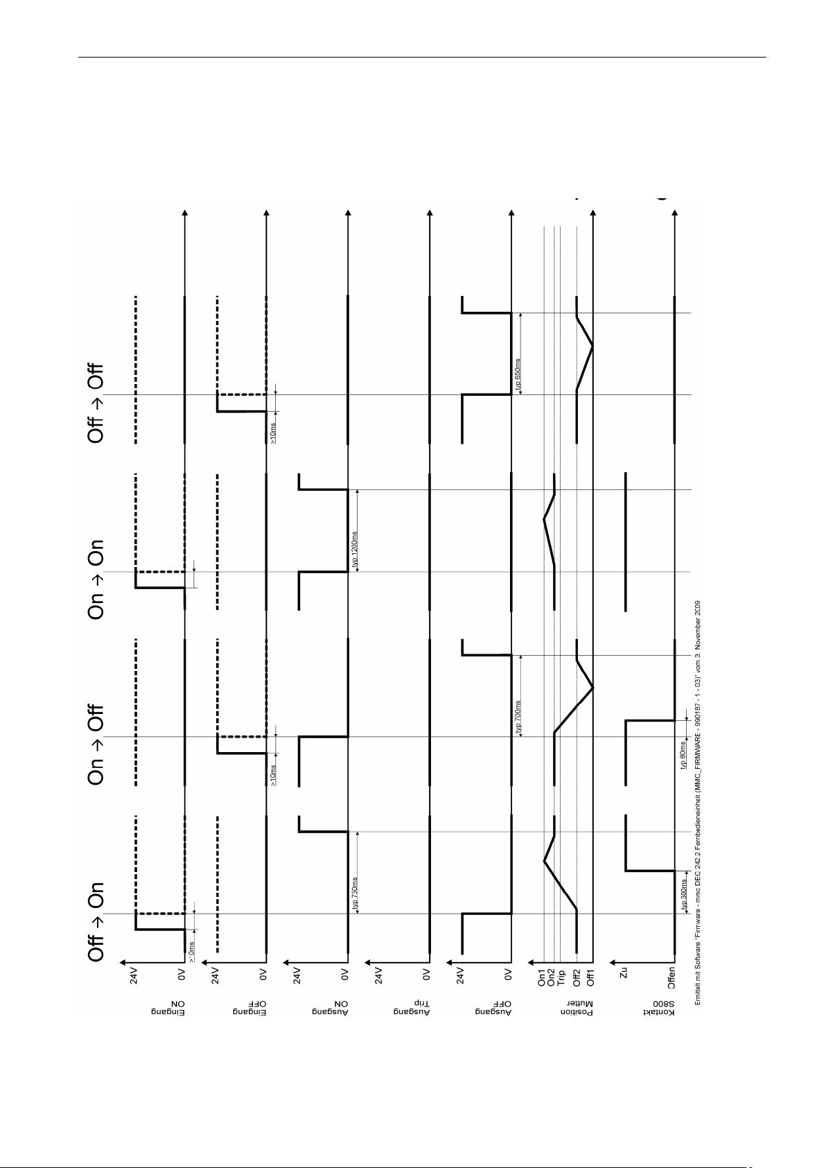
3 Exemplary Timing diagrams
3.1 OFF – ON / ON – OFF / ON – ON / OFF - OFF
Page 9

S800-RSU Technial Manual Page 9 / 10
3.2 Powerup if contacts are open resp. closed
Contacts are openPowerup Contacts are closed
Page 10

S800-RSU Technial Manual Page 10 / 10
3.3 ON – Trip / Trip – OFF / Trip – ON / Powerup - Trip
 Loading...