

Page 1
—
ABB MEASUREMENT & ANALYTICS | OPERATING INSTRUCTION
266CRx, 266CSx, 266JRx, 266JSx
Multivariable pressure transmitters
Engineered solutions for all
applications
Measurement made easy
—
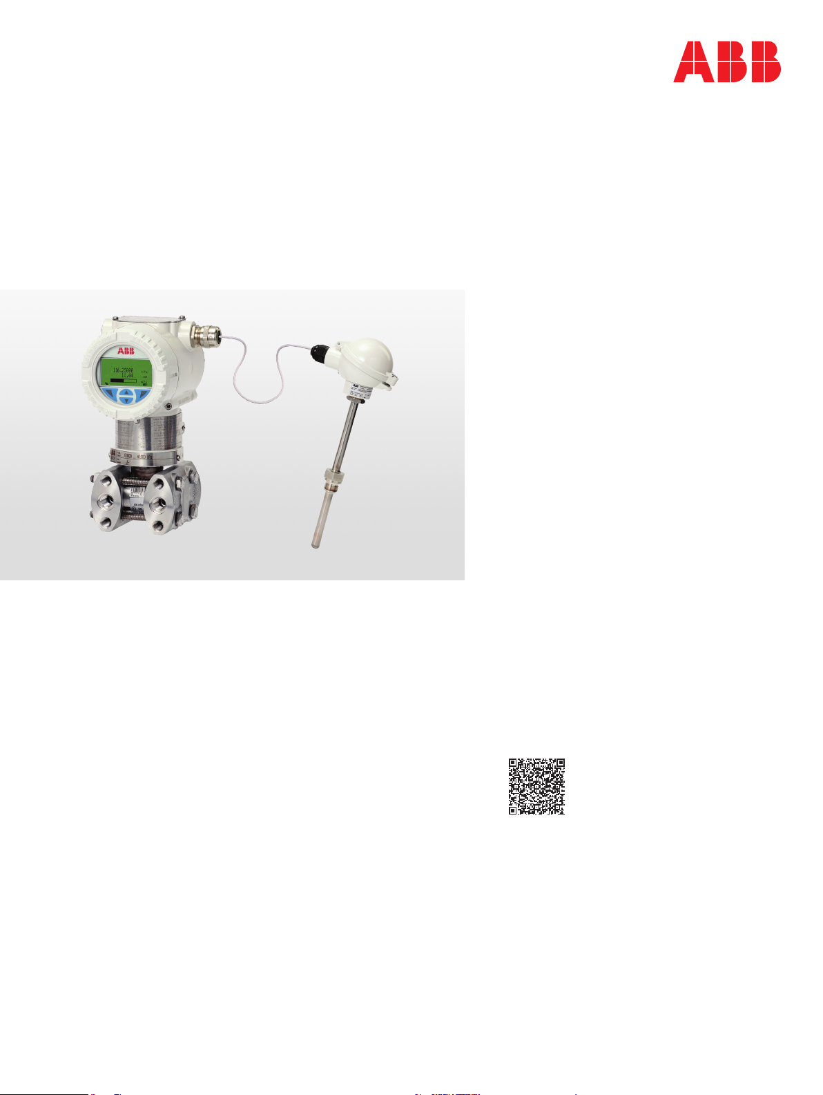
266 multivariable
Introduction
The 2600T family provides comprehensive range of
top quality pressure measurement products,
specifically designed to meet the widest range of
applications ranging from arduous conditions in
offshore oil and gas to the laboratory environment
of the pharmaceutical industry.
For more information
Further publications for 2600T series pressure
products are available for free download from:
www.abb.com/pressure
or by scanning this code:
Download the Brochure or search for
RB/2600T-EN on https://library.abb.com/en.
Page 2

Contents
1 ABB .............................................................................. 4
2 Introduction ................................................................... 4
2.1 About the manual ............................................. 4
2.2 Structure of the operating manual ...................... 4
2.3 Customer Service Centers worldwide ................ 4
3 Safety ........................................................................... 5
3.1 General information and notes for the reader ..... 5
3.2 Intended use .................................................... 5
3.3 Improper use .................................................... 5
3.4 Target groups and qualifications ........................ 5
3.5 Warranty provisions .......................................... 5
3.6 Plates and symbols ........................................... 6
3.6.1 Safety / warning symbols, note symbols ............ 6
3.7 Compliance with Pressure Equipment Directive
(2014/68/EU) .................................................... 6
3.8 Transport .......................................................... 6
3.9 Transport safety instructions ............................. 6
3.10 Obligations of the owner ................................... 6
3.11 Storage conditions ............................................ 7
3.12 Safety instructions for electrical installation ........ 7
3.13 Safety instructions for operation ........................ 7
3.14 Safety information for inspection and maintenance
........................................................................ 7
3.15 Returning devices ............................................. 7
3.16 Integrated management sys tem ........................ 7
3.17 Disposal ........................................................... 8
3.17.1 Information on WEEE Directive 2012/19/EU
(Waste Electrical and Electronic Eq uipment) ...... 8
3.17.2 ROHS Directive 2011/65/EU ............................. 8
3.18 Cyber security .................................................. 8
4 Unpacking the device .................................................... 8
4.1 Scope of delivery .............................................. 8
4.2 Identification ..................................................... 8
4.3 Storage ............................................................ 8
4.4 Handling ........................................................... 8
5 Product identification ..................................................... 9
6 Use in potentially explosive atmospheres ..................... 10
6.1 Hazardous atmospheres ................................. 10
7 Function and system design......................................... 11
7.1 Components of the pressure transmitter .......... 11
7.2 Product description ......................................... 11
7.3 Measuring range limits and span limits ............ 11
8 Mounting ..................................................................... 12
8.1 IP rating ......................................................... 12
8.2 Factory settings .............................................. 12
8.3 Venting / draining transmitters without diaphragm
seals .............................................................. 13
8.4 Mounting position ........................................... 13
8.5 Mounting dimensions 266CRx/JRx .................. 14
8.5.1 Transmitter with barrel housing ....................... 14
8.5.2 Transmitter with barrel housing and mounting
bracket, for vertical or horizontal mounting on
60 mm (2 in.) pipe ........................................... 15
8.5.3 Transmitter with DIN housing and mounting
bracket, for vertical or horizontal mounting on
60 mm (2 in.) pipe ........................................... 16
8.5.4 Transmitter with barrel housing and flat bracket,
for vertical or horizontal mounting on
60 mm (2 in.) pipe ........................................... 17
8.6 Mounting dimensions 266CSx/JSx .................. 18
8.6.1 Transmitter with barrel housing - Horizontal
flanges ........................................................... 18
8.6.2 Transmitter with barrel housing - Vertical flanges
...................................................................... 19
8.6.3 Transmitter with mounting bracket, for vertical or
horizontal mounting on 60 mm (2 in.) pipe pipe 20
8.6.4 Transmitter with DIN aluminum housing horizontal flanges with mounting bracket for
vertical or horizontal mounting on 60 mm (2 in.)
pipe ................................................................ 21
8.6.5 Transmitter with flat bracket, for vertical or
horizontal mounting on 60 mm (2 in.) pipe ....... 22
8.6.6 Installation via (optional) mounting brackets..... 23
8.7 Rotating the transmitter housing ...................... 23
8.8 Rotating the integral LCD display .................... 24
8.9 Connecting impulse lines ................................ 24
8.10 Process connections ....................................... 25
8.11 Temperature measurement ............................. 25
8.12 Mounting recommendations ............................ 25
8.12.1 Flow measurement of steam (condensible vapor)
or clean liquids ............................................... 26
8.12.2 Flow measurement of gas or liquid with solids in
suspension ..................................................... 26
8.12.3 Fill level measurement on closed tanks ........... 27
8.12.4 Fill level measurement on open tanks with fluids28
8.12.5 Fill level measurement on the s team boiler (drum
water level) ..................................................... 28
9 Electrical connections .................................................. 29
9.1 Cable connections .......................................... 29
9.2 Connection of the analog output (HART) ......... 30
9.3 Digital output (pulse / limit output).................... 31
9.4 Wiring ............................................................ 31
9.5 Protective conductor connection / grounding.... 31
2 OI/266CXX/266JXX/HART-EN Rev. C | 266CRx, 266JRx, 266CSx, 266JSx
Page 3

10 Commissioning ............................................................ 32
10.1 General remarks ............................................. 32
10.2 Output signal .................................................. 32
10.3 Zero point correction following installation ........ 32
10.3.1 Setting precalibrated devices ........................... 33
10.3.2 Zero-point increase/suppression on precalibrated
devices ........................................................... 33
11 Configuration ............................................................... 34
11.1 Write protection .............................................. 34
11.2 Hardware settings ........................................... 34
11.3 Factory settings .............................................. 35
11.4 Configuration of the transmitter without integrated
LCD display .................................................... 36
11.4.1 Configuration of LRV and URV (4 … 20 mA
range)............................................................. 36
11.5 Configuration of the pressure transmitter menu-
controlled without integrated LCD display ........ 37
11.5.1 Menu navigation ............................................. 37
11.5.2 Menu levels .................................................... 37
11.5.3 Activation of the operating menu ..................... 38
11.5.4 Selecting and changing parameters ................. 40
11.5.5 Easy Set-Up ................................................... 42
11.5.6 Overview of parameters on the configuration level
..................................................................... 44
11.6 Configuration with the PC / laptop or handheld
terminal .......................................................... 56
11.7 Damping and transmission function ................. 57
11.7.1 Damping ......................................................... 57
11.7.2 Transmission function ..................................... 57
14 Maintenance / Repair ................................................... 73
14.1 Dismounting ................................................... 73
14.2 Safeguard the housing cove r for devices with “Ex
d” type of protection ........................................ 73
14.3 Mounting / dismounting the button unit ............ 74
14.4 Mounting / dismounting the LCD display .......... 74
14.5 Measuring cell of the multivariable transmitter .. 74
14.6 Removing / installing the process flange .......... 75
14.6.1 Replacing the measuring cell........................... 75
12 Error messages ........................................................... 61
12.1 Error states and alarms ................................... 61
13 Ex relevant specifications ............................................. 67
13.1 Specific Conditions of Use (X) ......................... 67
13.2 Explosion protection requirements and IP rating
(ATEX) ........................................................... 67
13.3 Applications for "Ex ia" transmitters categories 1 G
and 1 D .......................................................... 67
13.3.1 Example applications ...................................... 68
13.4 Applications for Ex ia transmitters categories
1/2 G and 1/2 D .............................................. 69
13.4.1 Example applications ...................................... 69
13.5 Application for Ex d transmitters categories 1/2 G
and 1/2 D........................................................ 70
13.5.1 Example applications ...................................... 70
13.6 Applications for Ex nL transmitters Categories 3 G
and 3 D .......................................................... 71
13.6.1 Example applications ...................................... 71
13.7 Electrical data for the LCD display ................... 72
13.8 Explosion protection requiremen ts (North
America) ......................................................... 72
266CRx, 266JRx, 266CSx, 266JSx | OI/266CXX/266JXX/HART-EN Rev. C 3
Page 4

1 ABB
ABB is an established multinational company which
develops and manufactures products for measurement
technology.
We offer our customers application know-how, service, and
support all over the world.
The quality, accuracy, and performance of our products are
the result of more than 100 years of experience and ongoing
innovative developments featuring the very latest
technologies.
2.3 Customer Service Centers worldwide
For support of ABB instrumentation products local
subsidiaries are available worldwide. If it is not possible for
you to contact the ABB subsidiary in your country, you can
also contact one of the following competence centers for
pressure measurement technology.
ABB S.p.A.
Industrial Automation
Via Vaccani, 4 Loc. Ossuccio
22016 Tremezzina (Co)
Italy
Tel: +39 0344 58111
Fax: +39 0344 56278
2 Introduction
2.1 About the manual
This manual is an operating and maintenance manual for the
series 2600T pressure transmitter models. It contains
information on initial installation, configuration, calibration
and fault correction.
Read this manual before working with the product.
2.2 Structure of the operating manual
This manual describes the installation, operation, and fault
correction of model 266Jxx and 266Cxx pressure
transmitters. The sections of this manual describe the
individual phases of the product life cycle, starting with
delivery and identification of the transmitter, the installation
and electrical connection, configuration, extending to fault
correction and maintenance.
For special applications that are not considered in the
examples, we recommend that you first familiarize yourself
with the mode of operation of the pressure transmitter based
on this manual.
Helps for calibration or fault correction are provided directly
in the respective chapters.
If there are additional questions the user can contact ABB
directly. All addresses in this regard are on the last page of
this manual. Additional information is on the website at
www.abb.com/measurement.
ABB Inc.
Industrial Automation
125 E. County Line Road
Warminster, PA 18974
USA
Tel.: +1 215 674 6000
Fax: +1 (0)215 674 7183
measurement@us.abb.com
ABB Inc.
Industrial Automation
3450 Harvester Road
Burlington
Ontario L7N 3W5
Canada
Tel.: +1 905 639 8840
Fax: +1 (0)905 639 8639
ABB India Limited
Industrial Automation
Peenya Industrial Area, Peenya
Bangalore, Karnataka 560058
India
Tel.: +91 80 4206 9950
Fax: +91 (0)80 2294 9389
ABB Engineering (Shanghai) Ltd.
Industrial Automation
No. 4528, Kangxin Highway, Pudong New District,
Shanghai 201319
P.R. China
Tel.: +86 21 6105 6666
Fax: +86 (0)21 6105 6677
4 OI/266CXX/266JXX/HART-EN Rev. C | 266CRx, 266JRx, 266CSx, 266JSx
Page 5

3 Safety
3.1 General information and notes for the reader
These instructions are an important part of the product and
must be retained for future reference.
Installation, commissioning, and maintenance of the product
may only be performed by trained specialist personnel who
have been authorized by the plant operator accordingly. The
specialist personnel must have read and understood the
manual and must comply with its instructions.
For additional information or if specific problems occur that
are not discussed in these instructions, contact the
manufacturer.
The content of these instructions is neither part of nor an
amendment to any previous or existing agreement, promise
or legal relationship.
Modifications and repairs to the product may only be
performed if expressly permitted by these instructions.
Information and symbols on the product must be observed.
These may not be removed and must be fully legible at all
times.
The operating company must strictly observe the applicable
national regulations relating to the installation, function
testing, repair and maintenance of electrical products.
3.2 Intended use
The 266Jxx / 266Cxx multivariable pressure transmitters
measure the mass flow of gases, vapors, and liquids in the
process industry.
For information on measuring ranges and permissible
overload, refer to the section "Specifications".
3.3 Improper use
The following are considered to be instances of improper
use of the device:
— For use as a climbing aid, e.g. for mounting purposes
— For use as a support for external loads, e.g. as a support
for piping, etc.
— Material application, e.g. by painting over the housing,
name plate or welding/soldering on parts.
— Material removal, e.g. by spot drilling the housing.
3.4 Target groups and qualifications
Installation, commissioning and maintenance of the product
may only be performed by trained specialist personnel who
have been authorized by the plant operator to do so. The
specialist personnel must have read and understood the
manual and comply with its instructions.
The operators must strictly observe the applicable national
regulations with regards to installation, function tests,
repairs, and maintenance of electrical products.
3.5 Warranty provisions
Using the device in a manner that does not fall within the
scope of its intended use, disregarding this manual, using
underqualified personnel, or making unauthorized alterations
releases the manufacturer from liability for any resulting
damage. This renders the manufacturer's warranty null and
void.
Using these products as intended includes compliance with
the following points:
— Read and follow the instructions in this manual
— The technical limit values must be complied with (refer to
the section “Technical data").
266CRx, 266JRx, 266CSx, 266JSx | OI/266CXX/266JXX/HART-EN Rev. C 5
Page 6
3.6 Plates and symbols
3.6.1 Safety / warning symbols, note symbols
DANGER – Serious damage to health / risk to
life
This symbol in conjunction with the signal word
"DANGER" indicates an imminent danger.
Failure to observe this safety information will
result in death or severe injury.
3.7 Compliance with Pressure Equipment Directive
(2014/68/EU)
Devices with PS > 200
Devices with a permissible pressure of PS > 200 bar (20
MPa) have been tested for compliance by the notified body
(0474) according to module H and can be used for liquids of
group 1 (PED: 1G).
The rating plate contains the following designations: PED:
1G.
DANGER – Serious damage to health / risk to
life
This symbol in conjunction with the signal word
"DANGER" indicates an imminent electrical
hazard. Failure to observe this safety
information will result in death or severe injury.
WARNING – Bod ily injury
This symbol in conjunction with the signal word
"WARNING" indicates a potentially dangerous
situation. Failure to observe this safety
information may result in death or severe injury.
WARNING – Bod ily injury
This symbol in conjunction with the signal word
"WARNING" indicates a potential electrical
hazard. Failure to observe this safety
information may result in death or severe injury.
CAUTION – Minor injuries
This symbol in conjunction with the signal word
"CAUTION" indicates a potentially dangerous
situation. Failure to observe this safety
information may result in minor or moderate
injury. The symbol may also be used for
property damage warnings.
NOTICE – Property damage
This symbol indicates a potentially damaging
situation.
Failure to observe this safety information may
result in damage to or destruction of the product
and / or other system components.
Devices with PS ≤ 200
Devices with a permissible pressure PS ≤200 bar correspond
to article 4 paragraph 3. They have not been subject to a
conformity validation. These instruments were designed and
manufactured according to SEP Sound Engineering
Practices.
3.8 Transport
After final calibration, the device is packed in a carton to
provide protection against physical damage.
3.9 Transport safety instructions
Observe the following instructions:
— Do not expose the device to humidity during transport.
Pack the device accordingly.
— Pack the device so that it is protected against vibrations
during transport, e.g., by using air-cushioned packaging.
Prior to installation, check the devices for possible damage
that may have occurred as a result of improper transport.
Details of any damage that has occurred in transit must be
recorded on the transport documents. All claims for damages
must be submitted to the shipper without delay and before
installation.
3.10 O bligations of the owner
Prior to using the devices with corrosive or abrasive media,
the owner must check the level of resistance of all parts that
come into contact with the process liquid.
ABB would be pleased to provide support in the selection of
suitable materials, however we can assume no liability
whatsoever.
IMPORTANT (NOTE)
This symbol indicates operator tips, particularly
useful information, or important information
about the product or its further uses. The signal
word "IMPORTANT (NOTE)" does not indicate
a dangerous or harmful situation.
6 OI/266CXX/266JXX/HART-EN Rev. C | 266CRx, 266JRx, 266CSx, 266JSx
Page 7

3.11 Stor age conditions
— The device must be stored in dry and dust-free
conditions. Always keep the device in its original
package during storage / transport.
— Observe the permissible ambient conditions for transport
and storage according to the chapter “Technical Data”.
— In principle, the devices may be stored for an unlimited
period. However, the warranty conditions stipulated in
the order confirmation of the supplier apply.
3.12 Safet y instructions for electrical installation
The electrical connection may only be established by
authorized specialist personnel and in accordance with the
connection diagrams.
The electrical connection information in this manual must be
observed; otherwise, the IP rating may be adversely
affected.
Ground the measurement system according to requirements.
3.13 Safet y instructions for operation
Before switching on the device, make sure that your
installation complies with the environmental conditions listed
in the chapter “Technical Data” or on the data sheet.
If there is a chance that safe operation is no longer possible,
take the device out of operation and secure it against
unintended startup.
3.15 Retur ning devices
Use the original packaging or a secure transport container of
an appropriate type if you need to return the device for repair
or recalibration purposes. Fill out the return form (see the
Appendix) and include this with the device.
According to the EU Directive governing hazardous
materials, the owner of hazardous waste is responsible for
its disposal or must observe the following regulations for
shipping purposes:
All devices delivered to ABB must be free from any
hazardous materials (acids, alkalis, solvents, etc.).
3.16 I ntegrated management system
ABB actively promotes environmental awareness and has an
operational management system that meets the
requirements of ISO 9001:2015, ISO 14001:2015, and
OHSAS 18001:2007.
Our products and solutions are intended to have minimum
impact on the environment and persons during
manufacturing, storage, transport, use and disposal.
This includes the environmentally friendly use of natural
resources. ABB conducts an open dialog with the public
through its publications.
3.14 Safet y information for inspection and maintenance
WARNING – Electrical dangers!
When the housing is open, EMC protection is
impaired and there is no longer any protection
against accidental contact.
Switch off the power supply before opening the
housing.
Corrective maintenance work may only be performed by
trained personnel.
— Before removing the device, depressurize it and any
adjacent lines or containers.
— Check whether hazardous materials have been used as
materials to be measured before opening the device.
Residual amounts of hazardous material may still be
present in the device and could escape when it is
opened.
Within the scope of operator responsibility, check the
following as part of a regular inspection:
— the pressure-carrying walls / lining of the pressure
device
— the measurement-related function
— the leak tightness
— the wear (corrosion)
266CRx, 266JRx, 266CSx, 266JSx | OI/266CXX/266JXX/HART-EN Rev. C 7
Page 8

3.17 Disposal
This product is manufactured from materials that can be
recycled by specialist recycling companies.
3.17.1 Information on WEEE Directive 2012/19/EU (Waste
Electrical and Electronic Equipment)
This product or solution is subject to the WEEE Directive
2012/19/EU or corresponding national laws. Starting from
August 15th 2018, electrical and electronic equipment
marked with the crossed-out wheeled bin symbol may not be
disposed as unsorted municipal waste. Waste of electrical
and electronic equipment (WEEE) shall be treated
separately using the national collection framework available
to customers for the return, recycling and treatment of
WEEE.
Proper disposal prevents negative effects on people and the
environment, and supports the reuse of valuable raw
materials.
ABB can accept and dispose of returns for a fee.
3.17.2 ROHS II Directive 2011/65/EU
European Directives 2012/19/EU (WEEE) and 2011/65/EU
(RoHS II) define the products that are subject to regulated
collection and disposal or reuse in the event of disposal or at
the end of their service life. RoHS also prohibits the
marketing of electrical and electronic equipment that
contains certain amounts of lead, cadmium, mercury,
hexavalent chromium, polybrominated biphenyls (PBB), and
polybrominated diphenyl ethers (PBDE) (also known as
hazardous substances with restricted uses).
Standards/Specifications applied: EN 50581:2012.
The product provided by ABB complies with the
requirements of the substances restrictions at the time of
delivery. Contamination traces for which the manufacturer is
not responsible, cannot be ruled out according to generally
recognized rules of technology.
Change from tw o to one col umn
3.18 Cyber security
Disclaimer
This product is designed to be connected to and to
communicate information and data via a network interface. It
is operator’s sole responsibility to provide and continuously
ensure a secure connection between the product and your
network or any other network (as the case may be). Operator
shall establish and maintain any appropriate measures (such
as but not limited to the installation of firewalls, application of
authentication measures, encryption of data, installation of
anti-virus programs, etc) to protect the product, the network,
its system and the interface against any kind of security
breaches, unauthorized access, interference, intrusion,
leakage and/or theft of data or information.
ABB and its affiliates are not liable for damages and/or
losses related to such security breaches, any unauthorized
access, interference, intrusion, leakage and/or theft of data
or information.
Communication protocol specific
The HART protocol is an unsecured protocol, such as the
intended application should be assessed to ensure that
these protocols are suitable before implementation.
Change from one to two col umns
4 Unpacking the device
4.1 Scope of delivery
— Multivariable transmitter model 266Cxx or 266Jxx
— Multilingual Quick Reference Manual, calibration
protocol, and possibly optionally requested certificates in
an envelope.
— Hexagon socket wrench for unscrewing the fastening
screws of the housing
— Additional parts as specified in the purchase order:
— 1/2”-NPT-f adapter with appropriate seals
— Fastening accessories
— Accessories for the electrical connection
Change from tw o to one col umn
8 OI/266CXX/266JXX/HART-EN Rev. C | 266CRx, 266JRx, 266CSx, 266JSx
4.2 Identification
Identify the device in accordance with the instructions in
chapter “Product identification” to ensure it is the right
device.
4.3 Storage
Special measures are not required for storing the device in
shipping status and in accordance with the specified storage
conditions. The storage period is unlimited.
The guarantee conditions agreed with the company and
specified in the order confirmation remain unaffected.
4.4 Handling
Special precautionary measures are not required for
handling of the device. However, standard procedures must
be complied with.
Page 9
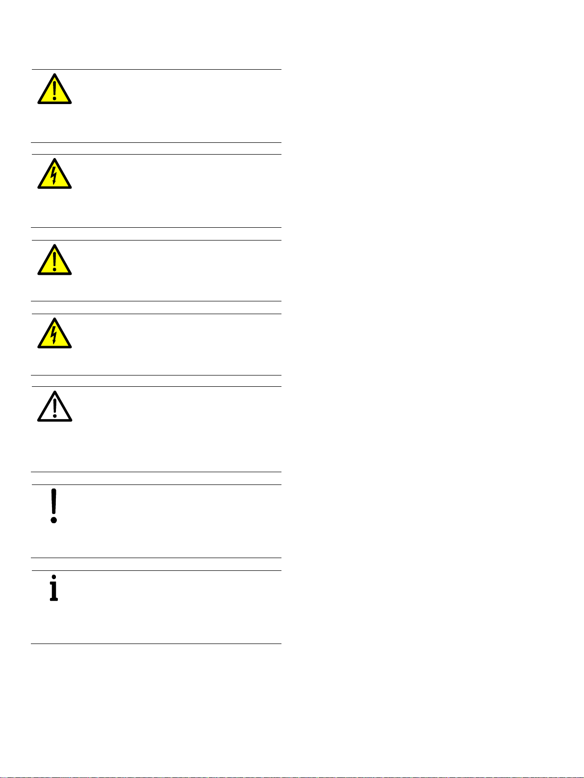
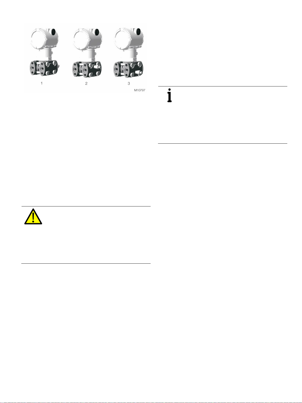
5 Product identification
ABB S.p .A.
Made in Italy
The device is identified via the signs (plates) presented in
Fig. 1.
The certification plate (A) is on the transmitter and indicates
whether the device is designed for general use or for use in
hazardous areas.
The name plate (B) provides information including the model
number, maximum operating pressure, measuring range
limits and span limits, power supply, output signal,
membrane material, filling fluid, serial number, maximum
permissible operating pressure (PS), and maximum
permissible temperature (TS).
Please specify the serial number when submitting inquiries
to the ABB customer service department.
Change from tw o to one col umn
An additional plate (C) provides the measuring point no. of
the client and the calibration range. The device can be used
as a pressure transfer accessory (category III) as defined by
the Pressure Equipment Directive 2014/68/EU. In this case,
you will find the number of the notified body that has verified
compliance next to the CE mark.
The certification plate shown (A) has been issued for ABB
S.p.A., 22016 Tremezzina (CO), Italy and bears the following
numbers:
— FM09ATEX0023X
— FM09ATEX0024X
— FM09ATEX0025X
CE-Identification number of the notified bodies to Pressure
Equipment Directive: 0474, to ATEX certification: 0722.
B
C
A
Fig. 1: Product identification
The figure shows the transmitter with barrel housing. The 266 series also includes transmitters with DIN housing. A"
Change from one to two col umns
Optional stainless steel attachment plate with customer data,
fastened with wire (option code I1)
The model 266 multivariable transmitter is delivered with an
optional stainless steel attachment plate with customer data
that is fastened with wire. Customer specific text that has
been specified in the purchase order is laser printed on the
attachment plate. For this, 4 lines of 32 characters each are
provided.
Fig. 2: Optional s t ainl es s s t eel at t ac hment plate with c us t omer data,
fastened with wire
266CRx, 266JRx, 266CSx, 266JSx | OI/266CXX/266JXX/HART-EN Rev. C 9
Page 10

6 Use i n poten tially explosive
atmospheres
6.1 Hazardous atmospheres
With or without integral LCD display
INTRINSIC SAFETY Ex ia:
ATEX Europe (c ode E 1) approv al
II 1 G Ex ia IIC T6...T4 Ga, II 1/2 G Ex ia IIC T6...T4 Ga/Gb,
II 1 D Ex ia IIIC T85 °C Da, II 1/2 D Ex ia IIIC T85 °C Da; IP66, IP67.
IECEx (code E 8) approval
Ex ia IIC T6...T4 Ga/Gb, Ex ia IIIC T85 °C Da; IP66, IP67.
NEPSI China (c ode E Y)
Ex ia IIC T4/T5/T6 Ga, Ex ia IIC T4/T5/T6 Ga/Gb,
Ex iaD 20 T85/ T100/ T135, Ex iaD 20/21 T85/ T100/ T135.
EXPLOSION PROOF:
ATEX Europe (c ode E 2) approv al
II 1/2 G Ex db IIC T6 Ga/Gb Ta=–50 °C to +75 °C,
II 1/2 D Ex tb IIIC T85 °C Db Ta = –50 °C to +75 °C; IP66, IP67.
IECEx (code E 9) approval
Ex db IIC T6 Ga/ Gb Ta=–50 °C to +75 °C,
Ex tb IIIC T85 °C Db Ta = –50 °C to +75 °C; IP66, IP67.
NEPSI China (c ode E Z)
Ex d IIC T6 Gb, Ex tD A21 IP67 T85 °C.
INTRINSIC SAFETY Ex ic:
ATEX Europe (c ode E 3 ) ty pe examinat ion
II 3 G Ex ic IIC T6...T4 Gc, II 3 D Ex tc IIIC T85 °C Dc;
IP66, IP67.
IECEx (code E R) ty pe examinat ion
Ex ic IIC T6...T4 Gc, Ex tc IIIC T85 °C Dc;
IP66, IP67.
NEPSI China (c ode E S) t y pe exami nat ion
Ex ic IIC T4~T6 Gc, Ex nA IIC T4~T6 Gc, Ex tD A22 IP67 T85 °C.
FM Approvals US (c ode E6) and
FM Approvals Canada (c ode E 4):
— Ex plosion proof (US): Class I, Zone 1 AEx d IIC T4 Gb
— Ex plosion proof (Canada): Class I, Zone 1 Ex d II C T4 Gb
— Noninc endiv e: Class I, Division 2,
Groups A, B, C, D T6...T4
— Energy li mited (US): Class I, Zone 2 AEx nC IIC T6...T4
— Energy li mited (Canada): Class I, Zone 2 Ex nC II C T6.. .T4
— Int rins ically saf e: Class I, II, III, Division 1,
Groups A, B, C, D, E, F, G T6...T4
Class I, Zone 0 AEx ia IIC T6...T4 (US)
Class I, Zone 0 Ex ia IIC T6...T4
(Canada)
Type 4X, IP66, IP 67 for all abov e mark ings.
COMBINED FM A pprovals US and Canada
— Int rins ically saf e (code EA )
COMBINED A TE X, FM and IE CEx A pprov als (c ode EN)
NEPSI combined (code EP = EY + EZ), (code EQ = EY + EZ + ES)
Technical Regulat ions Cus t oms Union EA C (Russia, K az akhst an,
Belarus), I nmetro (B razil )
For ambient temperatures -40 … 85°C (-40 … 185°F) the
information based on the temperature classes in the
associated certificates, must be complied with.
The temperature sensor circuit (Pt100) and the digital output
(pulse / limit value output) must be connected in accordance
with the requirements of the Ex certificate.
WARNING - General danger for Model 266
used in Zone 0!
The housing contains aluminum, which can lead
to a potential danger of ignition through impact
or friction. For this reason, impact or friction
must be avoided during installation and use.
10 OI/266CXX/266JXX/HART-EN Rev. C | 266CRx, 266JRx, 266CSx, 266JSx
Page 11
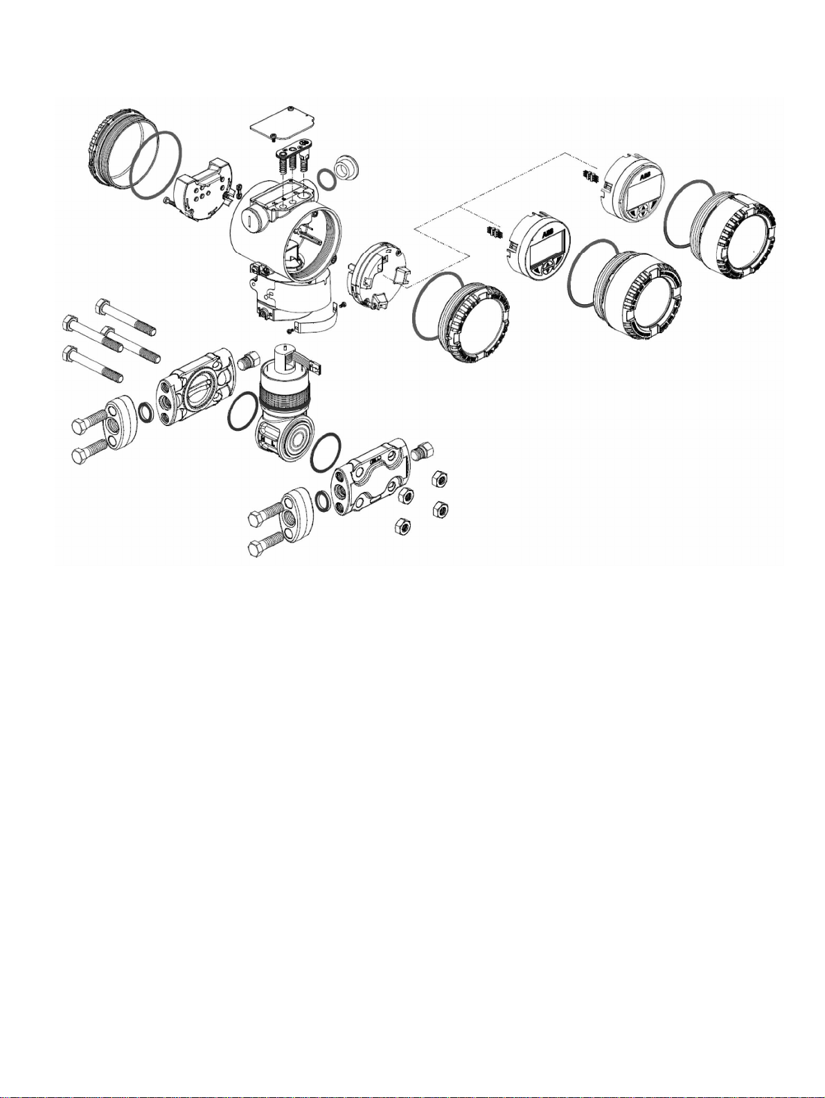
7 Function and system design
Change from tw o to one col umn
7.1 Components of the pressure transmitter
Fig. 3: Device ov erv iew
Change from one to two col umns
7.2 Product description
The 266Jxx/266Cxx multivariable pressure transmitters
measure the mass flow of gases, vapors, and liquids in
accordance with the differential pressure procedure and the
level of the liquids in the process industry. These
transmitters supply an analog or digital output signal.
Simultaneously and with high accuracy they measure
differential pressure, static pressure and with a Pt100 in 4conductor technology, they also measure the process
temperature. The differential pressure measuring ranges are
scaled from 1 to 2000 kPa. The measuring ranges for static
pressure are 0.6 to 2, 10 and 41 MPa. The transmitters can
be overloaded on one side to the respective upper
measuring range value of the static pressure.
7.3 Measuring range limits and span limits
The data sheets for the Series 2600T multivariable
transmitters contain all the information concerning the
measuring range and measuring span of the individual
models, as well as the sensor code.
The following terminology is used for the different
parameters:
URL: Upper Range Limit of a specific sensor. The highest
measured value t hat c an be measured by the transmitt er.
LRL: Lower Range Limit of a specific sensor. The lowest
measured value t hat c an be measured by the transmitt er.
URV: Upper Range Value The highest meas ured v alue to
which the transmitt er is cal ibrat ed.
LRV: Lower Range Value. The lowest measured value t o whic h
the transmitt er is c ali brated.
SPAN: Measuring span. The algebrai c diff erenc e bet ween t he
start of the meas uring range and t he end of the
measuring range. The s mal lest span is the s malles t v alue
that can be s elected wit hout i mpai ring t he s pec ified
measuring acc urac y.
TURN DOWN
RATIO:
Span ratio The ration between t he maxim um s pan and
the calibrat ed span.
The measuring transmitter can be calibrated to any
measuring range between LRL and URL with the following
restrictions.
— LRL ≤ LRV ≤ (URL - CAL SPAN)
— CAL SPAN ≥ MIN SPAN
— URV ≤ URL
266CRx, 266JRx, 266CSx, 266JSx | OI/266CXX/266JXX/HART-EN Rev. C 11
Page 12

8 Mounting
Before installing the transmitter, check whether the device
design meets the requirements of the measuring point from a
measurement technology and safety specifications point of
view. This applies in respect of the:
— Measuring range
— Overload resistance
— Temperature
— Explosion protection
— Operating voltage
The suitability of the materials must be checked as regards
their resistance to the media. This applies in respect of the:
— Gasket
— Process connection, separating diaphragm, etc.
8.1 IP rating
The housing of pressure transmitters of the R266 series
satisfies the requirements of IP degree of protection
IP 66 / IP 67 (NEMA 4X) in accordance with IEC 60529.
The first digit indicates the protection of the integrated
electronics against penetration of foreign objects, including
dust.
The digit “6” means that the housing is dust tight (i.e. dust
cannot penetrate). The second digit indicates the protection
of the integrated electronics against the penetration of water.
The digit “6” means that the housing is watertight and can
even withstand a strong water jet under the specified
conditions.
The digit “7” means that the housing is watertight and can be
temporarily immersed at a specified pressure and for a
specific time, without water penetrating.
In addition, the relevant directives, regulations, standards,
and accident prevention regulations must be observed (e. g.,
VDE/VDI 3512, DIN 19210, VBG, Elex V, etc.).
Measurement accuracy is largely dependent on correct
installation of the transmitter and, if applicable, the
associated impulse line(s).
As far as possible, the measuring setup should be free from
critical ambient conditions such as large variations in
temperature, vibrations, or shocks.
IMPORTANT (NOTICE)
If unfavorable ambient conditions cannot be
avoided for reasons relating to building
structure, measurement technology, or other
issues, the measurement quality may be
affected.
(See "Specifications" chapter).
If a remote seal with capillary tube is installed on the
transmitter, the additional operating instructions for remote
seals and the related data sheets must be observed.
8.2 Factory settings
The transmitter is factory configured according to the
customer’s order specifications.
IMPORTANT (NOTICE)
Under normal conditions no additional settings
are required.
The typical configuration includes:
— Number of the measuring point tag
— Calibrated span
— Configuration of the flow or liquid level calculation
— Configuration of the LCD display
12 OI/266CXX/266JXX/HART-EN Rev. C | 266CRx, 266JRx, 266CSx, 266JSx
Page 13
8.3 Venting / draining transmitters without diaphragm seals
Fig. 4
1 Valve on t he proces s axis | 2 Flange side v alve on t op |
3 Flange s ide v alve on t he bott om
For transmitters without diaphragm sealers the following
instructions on venting and draining must be complied with.
It is important to attach the transmitter in such a manner and
to layout the process line in such a manner that gas bubbles
in liquid measurements can be routed back into the process
and not get in to the measuring chambers.
The optional vent / drain valves on the transmitter are
attached on the measuring cell flanges. Align the transmitter
so that these vent / drain valves are arranged above the tap
points for liquid measurement, so that gas can escape
upward. For gas measurements align the transmitter so that
the vent / drain valves are arranged below the tap points, so
that air or condensate can drain.
8.4 Mounting position
The transmitter can be attached directly on a valve manifold
provided for flange installation.
Optionally a fastening bracket for wall or pipe installation
(2” pipe) is available as an accessory.
For models 266CRx and 266JRx fastening brackets must
always be used.
Ideally the transmitter must be mounted in such a manner
that the separating diaphragms are standing vertical, to
avoid later zero point offsets.
IMPORTANT (NOTICE)
If the transmitters are mounted with an
inclination that is not vertical, the filling fluid
exerts hydrostatic pressure on the measuring
diaphragm, which causes a zero point offset. In
this case the zero point can be adjusted via the
zero point button or with the command “Install
position correction”. See chapter
“Configuration”.
Change from tw o to one col umn
DANGER - severe health impairments / lifethreatening danger due to escaping
measurement medium!
During the venting or draining process medium
that is being discharged can escape and
endanger personnel who are not working in the
vicinity.
Consequently when venting or draining, any
escaping process medium must be collected.
266CRx, 266JRx, 266CSx, 266JSx | OI/266CXX/266JXX/HART-EN Rev. C 13
Page 14
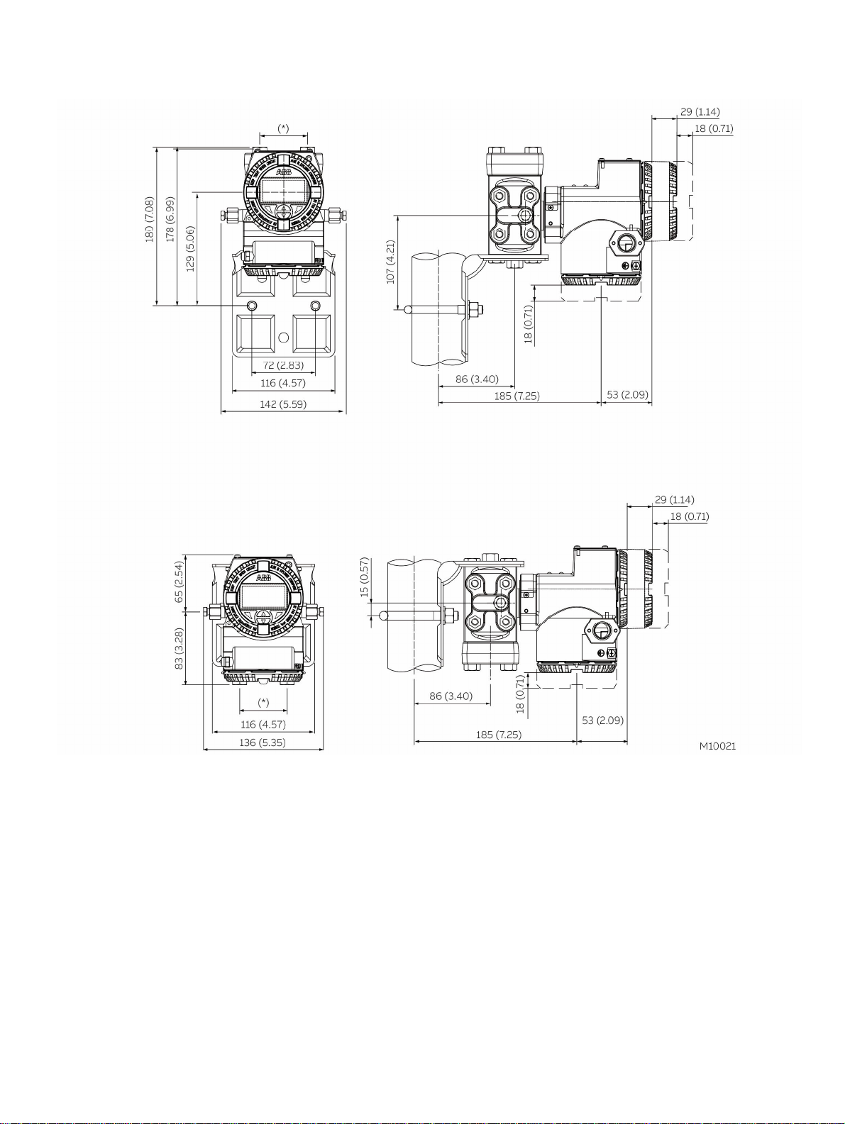
8.5 Mounting dimensions 266CRx/JRx
(No design information) - dimensions in mm (inch)
8.5.1 Transmitter with barrel housing
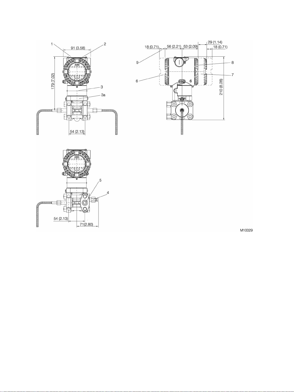
Fig. 5: B arrel ho us ing
1 Settings | 2 Rating plate | 3 Certification plate | 3a Optional plate (c ode I 2) | 4 V ent / drain v alve |
5 Process c onnec tion | 6 T ermi nal s ide | 7 LCD di s play hous ing cover | 8 Elect ronics si de | 9 Space for removing t he c over
Note
In the case of models with just one remote seal, the threaded connection (1/4 – 18 NPT directly or 1/2 – 14 NPT using
adapter) of the standard process flange, the gasket groove, and the gasket comply with IEC 61518.
The screw-on thread for attaching the adapter flange to the process flange is 7/16 -20 UNF.
14 OI/266CXX/266JXX/HART-EN Rev. C | 266CRx, 266JRx, 266CSx, 266JSx
Page 15
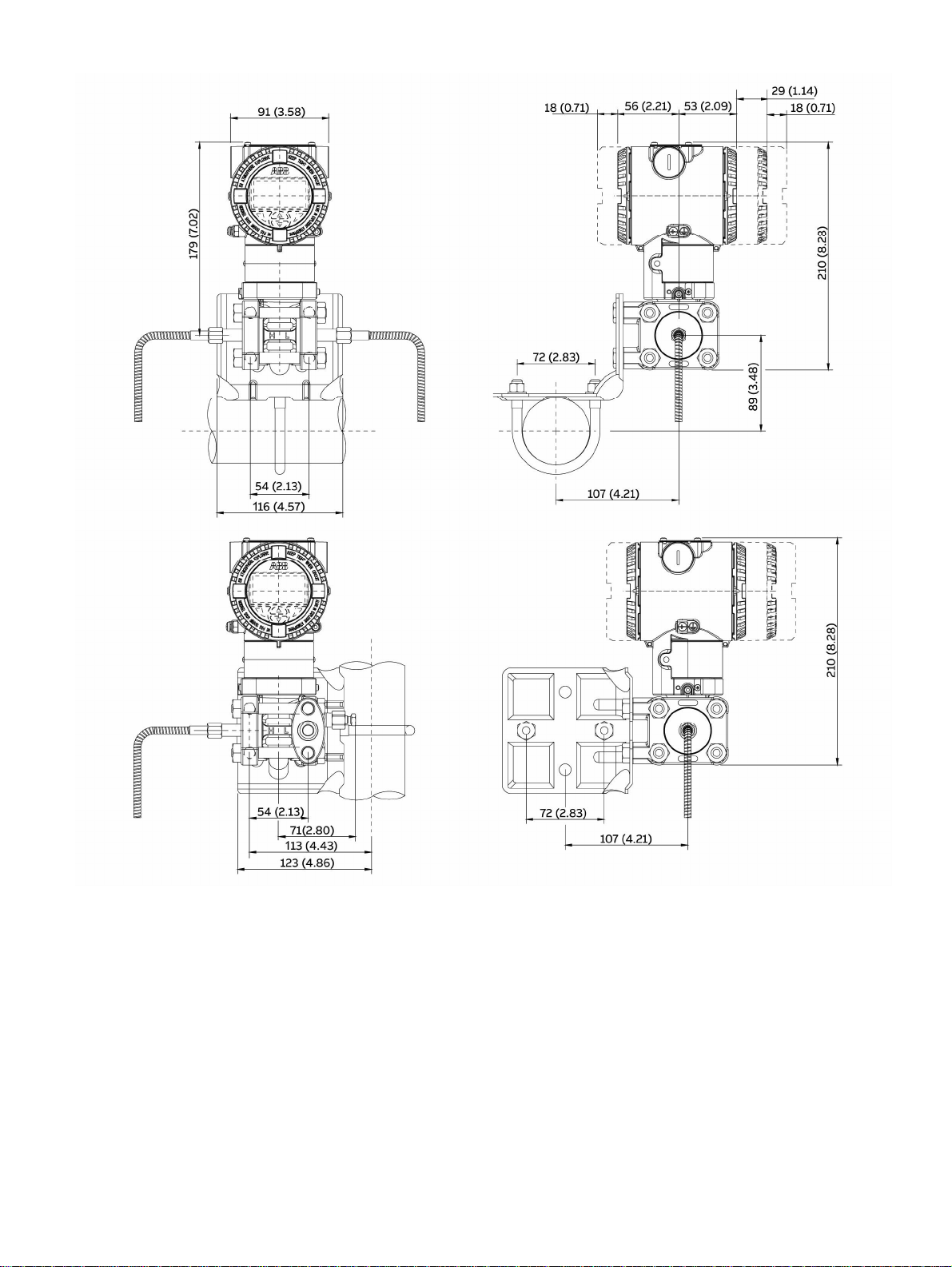
8.5.2 Transmitter with barrel housing and mounting bracket, for vertical or horizontal mounting on 60 mm (2 in.) pipe
Fig. 6: P ipe mount ing - barrel housing
266CRx, 266JRx, 266CSx, 266JSx | OI/266CXX/266JXX/HART-EN Rev. C 15
Page 16
8.5.3 Transmitter with DIN housing and mounting bracket, for vertical or horizontal mounting on 60 mm (2 in.) pipe
Fig. 7: P ipe mount ing - DIN h ous ing
16 OI/266CXX/266JXX/HART-EN Rev. C | 266CRx, 266JRx, 266CSx, 266JSx
Page 17
8.5.4 Transmitter with barrel housing and flat bracket, for vertical or horizontal mounting on 60 mm (2 in.) pipe
Fig. 8: Fl at brac k et f or pipe mounting - barrel hous ing
266CRx, 266JRx, 266CSx, 266JSx | OI/266CXX/266JXX/HART-EN Rev. C 17
Page 18
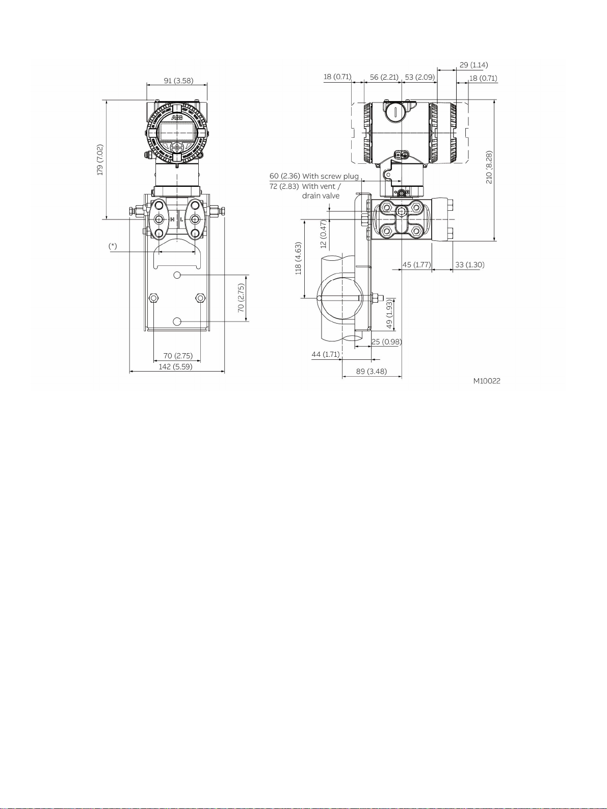
8.6 Mounting dimensions 266CSx/JSx
(not design data) - dimensions in mm (inch)
8.6.1 Transmitter with barrel housing - Horizontal flanges
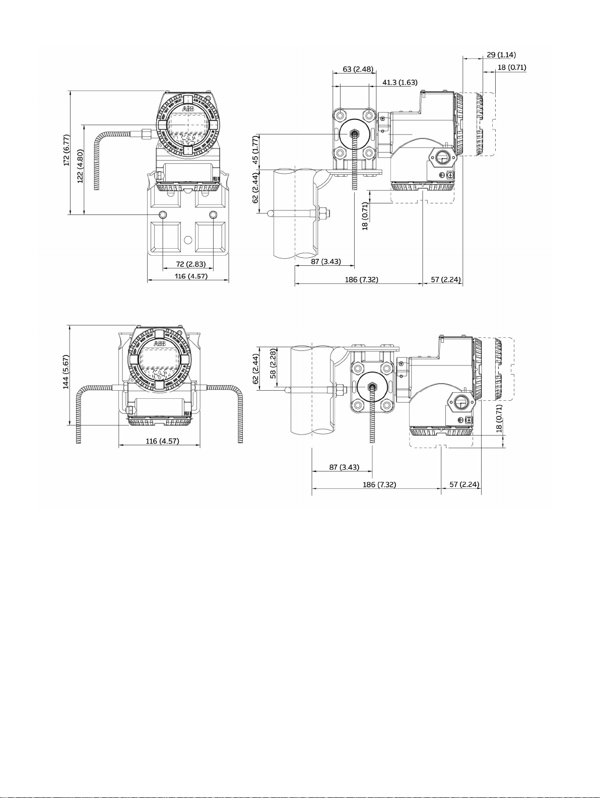
Fig. 9: B arrel ho us ing - horizontal flanges
1 Settings | 2 Rat ing plat e | 3 Cert ific ation plat e | 4 Vent / drain v alve | 5 Process connec t ion |
6 Terminal si de | 7 LCD di s play hous ing c ov er | 8 El ectronic s side | 9 P roc ess fl ange adapt er | 10 Space for removing t he c ov er
* 54 (2.13) mm (in.) via 1/4 - 18 NPT process flanges
51 (2.01), 54 (2.13), or 57 (2.24) mm (in) via 1/2 - 14 NPT adapter flanges.
Note: Process connect io n and sea l gro ove sat is fy I EC 161518. Thread for attaching adapt e r f lang es or ot he r c ompon ent s (e.g. , manif ol d) on t he p roc ess f lange:
7/16 -20 UNF.
** With screw plug
*** With vent / drain valve
18 OI/266CXX/266JXX/HART-EN Rev. C | 266CRx, 266JRx, 266CSx, 266JSx
Page 19
8.6.2 Transmitter with barrel housing - Vertical flanges
Fig. 10 : B arrel ho us ing - v e rt ical flanges
1 Settings | 2 Rat ing plat e | 3 Cert ific ation plat e | 4 Vent / drain v alve | 5 Process connec t ion |
6 Terminal si de | 7 LCD di s play hous ing c ov er | 8 El ectronic s side | 9 P roc ess fl ange adapt er | 10 Space for removing t he c ov er
266CRx, 266JRx, 266CSx, 266JSx | OI/266CXX/266JXX/HART-EN Rev. C 19
Page 20
8.6.3 Transmitter with mounting bracket, for vertical or horizontal mounting on 60 mm (2 in.) pipe pipe
Fig. 11 : P ipe mount ing - barrel housing
* 54 (2.13) mm (in.) via 1/4 - 18 NPT process flanges
51 (2.01), 54 (2.13), or 57 (2.24) mm (in) via 1/2 - 14 NPT adapter flanges.
Note: Process connect io n and sea l gro ove sat is fy I EC 161518. Thread for attaching adapt e r f lang es or ot he r c ompon ent s (e.g. , manif ol d) on t he p roc ess f lange:
7/16 -20 UNF.
** With screw plug
*** With vent / drain valve
20 OI/266CXX/266JXX/HART-EN Rev. C | 266CRx, 266JRx, 266CSx, 266JSx
Page 21
8.6.4 Transmitter with DIN aluminum housing - horizontal flanges with mounting bracket for vertical or horizontal mounting
on 60 mm (2 in.) pipe
Fig. 12 : P ipe mount ing - DIN h ous ing
* 54 (2.13) mm (in.) via 1/4 - 18 NPT process flanges
51 (2.01), 54 (2.13), or 57 (2.24) mm (in) via 1/2 - 14 NPT adapter flanges.
Note: Process connect io n and sea l gro ove sat is fy I EC 161518. Thread for attaching adapt e r f lang es or ot he r c ompon ent s (e.g. , manif ol d) on t he p roc ess f lange:
7/16 -20 UNF.
266CRx, 266JRx, 266CSx, 266JSx | OI/266CXX/266JXX/HART-EN Rev. C 21
Page 22
8.6.5 Transmitter with flat bracket, for vertical or horizontal mounting on 60 mm (2 in.) pipe
Fig. 13 : Fl at brack et f or pipe mounting - ba rr el housing
* With screw plug
** With vent / drain valve
Change from one to two col umns
22 OI/266CXX/266JXX/HART-EN Rev. C | 266CRx, 266JRx, 266CSx, 266JSx
Page 23
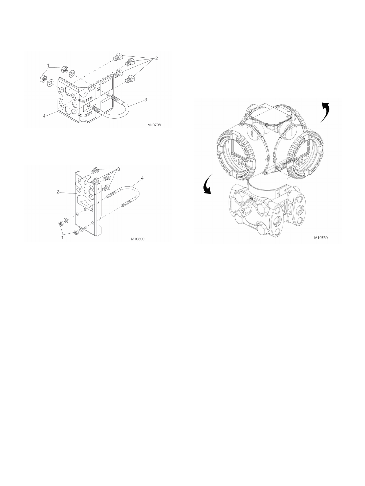
8.6.6 Installation via (optional) mounting brackets
With the mounting brackets available the transmitter can be
mounted in different positions.
Fig. 14 : Detail v ie w of the mounting brac k et , B2, f or pipe and wall
installat ion.
1 Washers and nuts f or f asteni ng t he U-bolt |
2 Mounting s c rews for t he trans mitter |
3 U-bolt | 4 Mounting bracket
8.7 Rotating the transmitter housing
To improve access to electrical connections and for better
visibility of the optional LCD display in the field, the
transmitter housing can be rotated through 360°. A stop
prevents the housing from being turned too far.
In order to rotate the housing, the fixing screw must be
loosened and unscrewed approx. one revolution (do not
remove it). As soon as the desired position is reached, the
fixing screw will be retightened.
Fig. 15: Detail view of the mounting bracket, B5
1 Washers and nuts f or f asteni ng t he U-bolt |
2 Mounting brac k et in f lange des ign, B 5 |
3 Mounting s c rews for t he trans mitter |
4 U-bolt
Fig. 16 : Rotat ing housing
266CRx, 266JRx, 266CSx, 266JSx | OI/266CXX/266JXX/HART-EN Rev. C 23
Page 24
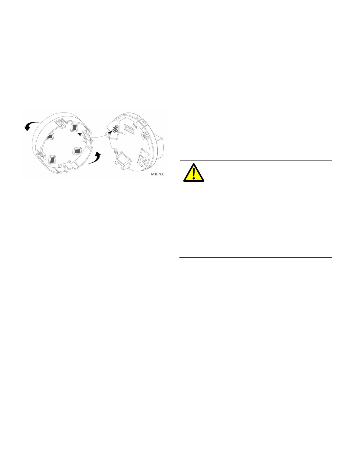
8.8 Rotating the integral LCD display
If the device has an integral LCD display, this can be
mounted in four different positions, each of which can be
rotated through 90°.
To rotate the LCD display, open the windowed cover
(ensuring compliance with special requirements for
hazardous areas) and pull the LCD display out of the
electronics module. Reposition the LCD display connector
accordingly. Plug the LCD display back into the electronics
module, checking that the 4 plastic fixing locks are securely
in place.
Fig. 17 : Rotat ing the LCD di splay
8.9 Connecting impulse lines
In order for the impulse lines to be laid correctly, the
following points must be observed:
— The impulse lines must be as short as possible and have
no sharp bends
— Lay the impulse lines so that no deposits can
accumulate in them. Gradients should not be less than
approx. 8 % (ascending or descending)
— The impulse lines should be blown through with
compressed air or, better still, flushed through with the
medium prior to connection
— With wet legs, the liquid in both lines must be at the
same level
— With vaporous measuring media, measures must be
taken to prevent steam entering the measuring
chambers of the measuring cell and causing overheating
— It may be necessary to use condensate vessels or
similar with small measuring spans and vaporous media
— If you are using condensate vessels (steam
measurement), you should ensure that the vessels are at
the same elevation in the differential pressure piping
— As far as possible, keep both impulse lines at the same
temperature
— Completely depressurize the impulse lines if the medium
is a liqu id
— Lay the impulse lines so that gas bubbles (when
measuring liquids) or condensate (when measuring
gases) can flow back into the process line
— Ensure that the impulse lines are connected correctly
(connection of high-pressure and low-pressure sides to
the measuring cell, seals, etc.)
— All connections must be secure and tight
— Lay the impulse lines so that the medium cannot be
blown out over the measuring cell
WARNING – bo dily injury!
Leaks in the process lines can result in death or
severe injuries.
Install and seal process connections and all
accessory elements (including valve blocks)
before the charging the device with pressure.
For applications with toxic or hazardous
substances prior to venting or draining, take all
precautionary measures that are recommended
in the respective safety data sheet. Only tighten
the screws of the fastening accessories with a
size 12 mm (15/32”) inch hexagon socket
wrench.
24 OI/266CXX/266JXX/HART-EN Rev. C | 266CRx, 266JRx, 266CSx, 266JSx
Page 25

8.10 Process connections
Fig. 18
On the flange of the 266 multivariable transmitter there are
1/4 – 18 NPT process connections with middle point
spacings of 54 mm (2.13 in.). The process connections on
the flange enable direct attachment of 3 element or 5
element valve manifolds.
Optionally flange adapters with 1/2 – 14 NPT connections
are available. By turning one or both adapters, middle point
spacing of 51 mm (2.01 in.), 54 mm (2.13 in.) or 57 mm
(2.24 in.) is possible.
Mount the adapters as follows:
1. Correctly position the adapters with inserted O-ring.
2. Screw the adapters on the transmitter connection flange
with the provided screws.
Tighten the scr ews as follows: Preliminary tightening
hand tight, preliminary tightening with 10 Nm, final
tightening with 50 Nm.
8.11 Temperature measurement
— Mount the temperature sensor in the downstream pipe of
the primary element.
— Consider the downstream straight pipe requirements .
— If there is a significant difference between the
temperature of the measuring medium and the ambient
temperature, the measuring error caused by heat
conduction must be minimized by insulating the
installation location accordingly.
— Use class "A" sensors to maximize accuracy.
— The lengths of the protective tubes should be
15 ... 20 times the diameter of the protective tube for gas
measurements and 3 ... 5 times the diameter of the
protective tube for liquid measurements.
8.12 Mounting recommendations
The arrangement of the impulse lines depends on the
respective measurement application.
266CRx, 266JRx, 266CSx, 266JSx | OI/266CXX/266JXX/HART-EN Rev. C 25
Page 26

8.12.1 Flow measurement of steam (condensible vapor) or
clean liquids
8.12.2 Flow measurement of gas or liquid with solids in
suspension
Fig. 19 : St eam f low measurement
A High-press ure v alve | B Low press ure v alve |
C Equaliz ing v alve | H High pres s ure s ide | L Low pres s ure side
Place taps to the side of the process line.
For liquid measurements, mount the transmitter next to or
underneath the taps, for steam measurements underneath
the taps.
Mount the vent / drain valve pointing upward.
For steam applications, fill the vertical section of the impulse
lines with a compatible fluid through the appropriate filling
connections.
The height of the liquid column between process line and
transmitter must be the same on the high pressure side and
the low pressure side, so that an accurate measurement is
ensured. For implementation of this requirement it can be
practical for steam measurements, to use the impulse lines
condensate tanks.
To commission the transmitter, operate the valves in the
following sequence:
1. Open the equalizing valve (C)
2. Close the low pressure valve (B) and high pressure
valve (A).
3. Open the primary shutoff valves
4. Slowly open the high pressure valve (A) so that the
measuring medium can flow into the measuring cell on
both sides.
5. Vent or drain the measuring cell and close the valves.
6. Open the low pressure valve (B) and close the
equalizing valve (C).
Fig. 20 : Flow measureme nt of gas es or li q uids
A High-press ure v alve | B Low press ure v alve |
C Equaliz ing v alve | H High pres s ure s ide | L Low pres s ure side
Place taps above or to the side of the line.
Mount the transmitter above the taps.
To commission the transmitter, operate the valves in the
following sequence:
1. Open the equalizing valve (C)
2. Close the low pressure valve (B) and high pressure
valve (A).
3. Open the primary shutoff valves
4. Slowly open the high pressure valve (A) so that the
measuring medium can flow into the measuring cell on
both sides.
5. Vent or drain the measuring cell and close the valves.
6. Open the low pressure valve (B) and close the
equalizing valve (C).
26 OI/266CXX/266JXX/HART-EN Rev. C | 266CRx, 266JRx, 266CSx, 266JSx
Page 27

8.12.3 Fill level measurement on closed tanks
Non-condensing measuring medium (dry leg)
Condensing measuring medium (wet leg)
Fig. 22 : Level measurement on c los ed t ank s (w et leg)
Fig. 21 : Level measurement on c los ed t ank s (dry leg)
Mount the transmitter at the same height or below the lowest
level to be measured.
Connect the high pressure side "+" (H) of the transmitter to
the bottom of the tank.
Connect the low pressure side "-" (L) of the transmitter to the
top of the tank, above the maximum level.
Mount the transmitter at the same height or below the lowest
level to be measured.
Connect the high pressure side "+" (H) of the transmitter to
the bottom of the tank.
Connect the low pressure side "-" (L) of the transmitter to the
top of the tank, above the maximum level.
Fill the vertical part of the impulse line of the low pressure
side with a compatible filling liquid via the appropriate filling
connections.
266CRx, 266JRx, 266CSx, 266JSx | OI/266CXX/266JXX/HART-EN Rev. C 27
Page 28

8.12.4 Fill level measurement on open tanks with fluids
Fig. 23 : Level measurement on op en t ank s
Mount the transmitter at the same height or below the lowest
level to be measured.
Connect the high pressure side "+" (H) of the transmitter to
the bottom of the tank.
Leave the low pressure side “–” (L) of the transmitter open to
the atmosphere.
8.12.5 Fill level measurement on the steam boiler (drum
water level)
Fig. 24 : Level measurement on the s t eam boiler
Mount the transmitter at the same height or below the lowest
level to be measured.
Connect the high pressure side "+" (H) of the transmitter to
the bottom of the tank.
The low pressure side “–” (L) of the transmitter up at the
tank. Above the maximum level, connect using a condensate
vessel.
Use the condensate tank to ensure that the impulse line of
the low pressure side is always filled with liquid (condensate)
at a constant height.
28 OI/266CXX/266JXX/HART-EN Rev. C | 266CRx, 266JRx, 266CSx, 266JSx
Page 29

9 Electrical connections
The relevant directives must be complied with for the
electrical installation!
Because the transmitter cannot be switched off, surge
protection devices, lightning protection, or grid disconnect
possibilities must be provided at the plant.
NOTICE - material damage due to electrostatic
discharge!
An open cover does not provide contact
protection. Touching conductive parts can
damage electronic components (in some cases
beyond repair) due to electrostatic discharge.
Therefore, do not touch conductive
components.
Check that the existing supply voltage corresponds to that
indicated on the rating plate. The same lines are used for
both the power supply and the output signal.
If an optional surge protector is provided and if the
transmitter is used in a hazardous area, energy must only be
supplied via a voltage source with galvanic isolation from the
grid. Because the inherently safe power circuits of the
transmitter are grounded, a sufficient equipotential bonding
must be ensured for the entire supply line.
DANGER – explosion hazard!
If the type of protection specified on the
certification plate does not agree with the
requirements imposed on the implementation
site, explosions or fires can be triggered. In this
case the transmitter must NOT be connected
electrically.
DANGER - severe health impairments / lifethreatening danger!
The lines can carry dangerous touch voltages
and cause electric shocks. An electric shock
can be fatal or can cause serious injuries.
Consequently do not touch the conductors and
connection terminals.
Change from tw o to one col umn
9.1 Cable connections
The electric connection is made using a 1/2-14 NPT or
M20 x 1.5 cable entry. Basically, a metal cable gland should
be provided for th Pt100 cable, since a shielded cable will be
used. Connect the shielding within the metal cable gland!
To ensure an 4X and IP 66-67 IP rating for the transmitter,
the cable gland must be screwed into the housing (1/2" NPT
female thread) using a suitable sealing compound.
IMPORTANT (NOTICE)
If cable glands are not used, the red transport
screw plugs must be replaced with suitable
screw plugs when the transmitter is installed.
This is because the transport screw plugs are
not certified as protected against explosion.
This requirement is particularly relevant in
hazardous areas.
IMPORTANT (NOTICE)
For the purpose of simulation, a 178 Ω resistor
(206°C / 402.8°F) with 2 jumpers has been
installed between the terminals for the Pt100
connection. This resistor (including the jumpers
in the case of 4-wire connections) must be
removed before connecting the Pt100. If a
Pt100 is not connected, the resistor must not be
moved.
IMPORTANT (NOTICE)
For category 3 transmitters for use in “Zone 2” a
type of protection approved for this cable gland
must be provided by the customer (see chapter
“Ex-relevant technical data”). An appropriate
thread M20 x 1.5 must be provided in the
electronics housing for this purpose.
for transmitters with “Ex d”, Flameproof
Enclosure” the housing cover must be arrested
with the securing screw.
The screw plug possible provided with the
transmitter must be inserted on site with the
sealant, Molykote DX. If a different sealant is
used, the responsibility rests with the executing
installer.
At this point we expressly state that after
several weeks the housing cover can only be
unscrewed with an increased expenditure of
force. This is not caused by the threads, but
instead is due solely to the type of seal.
266CRx, 266JRx, 266CSx, 266JSx | OI/266CXX/266JXX/HART-EN Rev. C 29
Page 30

9.2 Connection of the analog output (HART)
Fig. 25 : Elec t rical connect ions
1 Digital out put | 2 Connec tion for Pt100 res ist anc e thermom et er | 3 Int ernal ground c onnec tion | 4 External ground connec t ion |
5 Remote display | 6 Handheld termi nal | 7 P ower s upply
Change from one to two col umns
For connection of signal voltage / supply voltage twisted
cable with a conductor cross section of 18 … 22 AWG /
0.8 … 0.35 mm2 to2 to max. 1500 m length must be used.
Avoid cable installation, together with other power lines (with
inductive load, etc.), as well as the vicinity to large electrical
installations.
For longer leads a greater cable cross section is required.
For shielded cables the cable shielding must only be placed
on one side (not on both sides). For the grounding on the
transmitter the inner terminal marked with can also be
used. The output signal (4 ... 20 mA) and the power supply
are conducted via the same conductor pair. The transmitter
always works with a supply voltage between 10.5 and 42 V
DC.
The HART handheld terminal can be connected to any
connection point in the circuit if a resistance of at least
250 Ω is present in the circuit. If there is resistance less than
250 Ohm an additional resistor must be provided to enable
communication. The handheld terminal is connected
between the resistor and transmitter, not between the
resistor and the power supply.
For devices with “Ex ia” type of protection, “Intrinsic Safety”
(FM, CSA, and SAA approval) the supply voltage must not
exceed 30 V DC. In some countries the maximum supply
voltage is limited to lower values. The permissible supply
voltage is specified on the name plate on the top of the
transmitter.
The possible line length depends on the total capacity and
the total resistance and can be estimated based on the
following formula.
65 x 10
L =
6
C
+ 10000
f
-
R x C C
L = Line length in meters
R = Total resistance in Ohm
C = Line capacity
Cf = Maximum internal capacity in pF of the HART field
devices in the circuit
30 OI/266CXX/266JXX/HART-EN Rev. C | 266CRx, 266JRx, 266CSx, 266JSx
Page 31

9.3 Digital output (pulse / limit output)
This digital output can be set as a pulse or limit output
(transistor output) by making parameter changes using the
software.
NPN transistor with open-collector output
Contact swit c hing c apac ity 10 … 30 V, m axim um 120 mA DC
Low-level output v oltage 0 … 2 V
High-level out put v oltage Maximum 30 V
Quiescent current 500 µA
9.4 Wiring
Proceed as follows to wire the transmitter:
— Unscrew the transport screw plug from one of the two
cable entries located on both sides in the upper part of
the transmitter housing
— These cable entries have a 1/2 inch NPT or M20x1.5
female thread. Various adapters and bushings can be
fitted to these threads to comply with plant wiring
(conduit) standards
DANGER - Risk to life due to explosion!
In an explosion-proof / flameproof installation in
a hazardous area, the housing cover of the
terminal compartment must not be removed
when the voltage is connected, as an explosion
may be caused by spark formation. Before
removing the housing cover of the terminal
compartment, disconnect the equipment from
the supply voltage and take suitable measures
to prevent reconnection.
— Remove the housing cover from the terminal
compartment.
— Run the connection cable through the opening and
connect the + wire to the + terminal and the - wire to the
– terminal.
— Run the temperature sensor cable (if there is one)
through the second cable entry and connect it to the
designated terminals
IMPORTANT (NOTICE)
Do not connect the supply voltage across the
test terminals. It could damage the test diode in
the test connection.
— Replace the housing cover on the terminal compartment
and tighten it by hand until the cover contacts the
housing metal-to-metal. To prevent the housing cover
from turning, in "Ex-d” type of protection (flameproof
enclosure) installations, lock it by turning the locking
screw / hex-head screw anti-clockwise with the
2 mm Allen key supplied with the device.
1 Cover safety screw
Fig. 26
WARNING – bo dily injury!
If the cables, cable glands and stopper plugs
used for the electrical connection do not satisfy
the requirements for the type of protection (e.g.
intrinsic safety, flameproof enclosure, etc.) and
the necessary degree of protection for the
housing (e.g. IP 6x in accordance with IEC EN
60529 or NEMA 4x), explosions or fires can be
triggered.
For this reason, the red plastic transport caps
must be replaced with cable glands or stopper
plugs, that are approved for the required type of
protection and the required degree of protection
for the housing. See section “Ex-relevant
technical data”.
9.5 Protective conductor connection / grounding
For the ground (PE) of the transmitter or the connection of a
protective conductor, a connection is available on the
exterior of the housing, and also in the terminal
compartment. Both connections must be galvanically
connected to one another. These connection points can be
used if grounding or the connection of a protective conductor
is prescribed by national regulations for the selected type of
supply or the type of protection used.
— Plug and seal the cable entries. Make sure that when the
installation has been completed, these openings are
properly sealed to prevent the entry of rain and corrosive
vapors and gases. In particular, for "Ex-d" (flameproof
enclosure) installations, plug unused openings with a
suited sealing plug that has been certified for explosion
protection.
— If applicable, install the connection cable with a drip
loop. Arrange the drip loop so the lower part is located
below the cable entry and the transmitter housing
Fig. 27
266CRx, 266JRx, 266CSx, 266JSx | OI/266CXX/266JXX/HART-EN Rev. C 31
Page 32

10 Commissioning
10.1 G eneral remarks
Once the pressure transmitter has been installed, it is put
into operation by switching on the operating voltage.
Prior to switching on the operating voltage check:
— Process connections
— Electrical connection
— Complete filling of the impulse line and measuring
chamber of the measuring cell with the measuring
medium.
The transmitter can then be put into operation.
To do this, the valves must be actuated in the following order
(in home position, all valves are closed):
1. Open the shut-off valves on the pressure tap connection
(if present).
2. Open the pressure equalization valve of the valve block.
3. Open the shut-off valve of the high pressure side (H) on
the valve block.
4. Open the shut-off valve on the low pressure side (L) on
the valve manifold.
5. Close the pressure equalization valve.
Decommissioning is executed in the reverse sequence.
If, when using transmitters with type of protection "intrinsic
safety", an ammeter is connected to the output circuit or a
modem is connected in parallel while there is a risk of
explosion, the sums of the capacitances and inductances of
all circuits, including the transmitter (see EC-typeexamination certificate) must be equal to or less than the
permissible capacitances and inductances of the intrinsically
safe signal circuit (see EC-type-examination certificate for
the power supply unit).
Only passive or explosion-proof test devices or display
instruments may be connected.
10.2 O utput signal
If the applied pressure is within the values indicated on the
rating plate, the output current ranges between 4 and 20 mA.
If the pressure applied falls outside the set range, the output
current will be between 3.5 mA and 4 mA if the range is
underranged or between 20 mA and 22 mA if the range is
overrranged (depending on the respective configuration).
Standard setting for normal operation
3.8 mA / 20.5 mA
A current that is < 4 mA or > 20 mA may also indicate that
the microprocessor has detected an internal error.
Standard setting for error detection
21.8 mA
In this case diagnosis of the error can be executed with the
aid of different configuration tools.
IMPORTANT (NOTICE)
A brief interruption in the power supply results
in initialization of the electronics (program
restarts).
10.3 Zero point correction following installation
Once the transmitter has been installed, it is advisable to
check the zero point and correct it if necessary.
If the output signal stabilizes only slowly, it is likely that a
large damping time constant has been set on the transmitter.
32 OI/266CXX/266JXX/HART-EN Rev. C | 266CRx, 266JRx, 266CSx, 266JSx
Fig. 28: Operating buttons, write protection turn switch
1 Zero | 2 Span | 3 Write protection switch
Page 33

10.3.1 Setting precalibrated devices
(The lower range value has already been set to 0.)
266Cxx transmitters do not support this function if the "Level
measurement" calculation function has been activated. In
this case, the correction must be made using the optional
LCD indicator, the handheld terminal, or the DTM.
IMPORTANT (NOTICE)
For this purpose, the DIP switch on the
electronics board must be set to position 1.
A PV Bias / Offset correction can be performed via the local
push buttons as follows:
— Separate the transmitter from the process and equalize
the pressure in the two measuring chambers by
adjusting the bypass valve in the manifold.
— Check the transmitter output signal
If it is at 4 mA (or PV = 0), zero point correction is not
required.
I f t he output is not at zero, proceed as follows:
— Unscrew the screws attaching the name plate to the top
of the transmitter housing
— Rotate the name plate so that the push buttons can be
accessed
— Check that the write protection rotary switch is set to
write enable
— Press and hold down the zero button (Z) on the top of
the transmitter for at least 3 seconds
The output signal switches to 4 mA and the message
“OPER DONE” appears on the LCD display (if there is
one).
— If nothing happens, check the write protection rotary
switch.
It is probably set to write protection.
— For all other diagnosis notices, refer to the instructions
— As soon as zero point correction is complete, reconnect
the transmitter to the process
— Open the pressure equalization valve on the manifold.
— Open the shut-off valve of high-pressure side
— Open the pressure equalization valve on the manifold.
— Open the shut-off valve on the low-pressure side
10.3.2 Zero-point increase/suppression on precalibrated
devices
(e.g., 4 ... 20 mA = -100 ... 100 mbar)
This function is only supported by 266Jxx and 266Cxx
transmitters if the calculation function has been disabled.
IMPORTANT (NOTICE)
For this purpose, the DIP switch on the
electronics board must be set to position 0.
— Isolate the transmitter from the process and vent the
transmitter measuring chamber(s) to atmosphere
— Apply the lower range value pressure (4 mA).
The pr essure must be stable and applied with a high
level of accuracy (< 0.05 %, observing the set damping
value)
— Check the transmitter output signal
If it is at 4 mA (or PV = 0), zero point correction of the
transmitter is not required.
I f t he output is not at zero, proceed as follows:
— Unscrew the screws attaching the name plate to the top
of the transmitter housing
— Rotate the name plate so that the push buttons can be
accessed
— Check that the write protection rotary switch is set to
write enable.
— Press and hold down the zero button (Z) on the top of
the transmitter for at least 3 seconds
The output signal switches to 4 mA and the message
“OPER DONE” appears on the LCD display (if there is
one)
— If nothing happens, check the write protection rotary
switch.
It is probably set to write protection.
— For all other diagnosis notices, refer to the instructions
— As soon as zero point correction is complete, reconnect
the transmitter to the process
— Open the pressure equalization valve on the manifold.
— Open the shut-off valve of high-pressure side
— Open the pressure equalization valve on the manifold.
— Open the shut-off valve on the low-pressure side
IMPORTANT (NOTICE)
After the transmitter has been adjusted as
described above, the zero bias / offset value is
activated and stored in the memory of the
transmitter. In this case calibration of the
transmitter is can no longer be executed. Only if
the PV bias / offset value is reset, will a sensor
calibration be possible again.
266CRx, 266JRx, 266CSx, 266JSx | OI/266CXX/266JXX/HART-EN Rev. C 33
Page 34

11 Configuration
The transmitter is delivered preconfigured according to the
information provided when placing the order. However,
should a change to the configuration be necessary (because
measuring point data has changed since the original plans
were drawn up, for example), the following options are
available:
— Local keypad for the LRV / URV setting (266Jxx only)
and zero point correction following installation
— Menu-led configuration of the transmitter with the
integrated LCD indicator
— Configuration using a handheld terminal
— Configuration using a PC / laptop with graphical user
interface (DTM)
How to use these tools to make the configuration settings is
described in the corresponding related documentation.
11.1 Wr ite protection
The write protection prevents unauthorized users from
overwriting the configuration data. With activated write
protection the operating buttons "0% (Z)" and "100 % (S)"
have no function.
A change of parameters with the integral LCD indicator, via a
handheld terminal, or the user interface (DTM) are not
possible either.
However the configuration data can be read out via the
graphic user interface (DTM) or a comparable
communication tool. If needed the operating device can also
be sealed with a lead seal.
Write protection can be activated as follows (see also the
symbols on the plate).
1. Use a suitable screwdriver to press the switch all the
way down.
2. Turn the switch 90° clockwise.
11.2 Hardware settings
Fig. 30: DIP switches (example, HART version)
There are six DIP switches on the secondary electronics.
They are used to make settings if an LCD display is not
present.
DIP switches 1 and 2 activate REPLACE MODE for the
sensor and the secondary electronics (NEW SENSOR / NEW
ELECTRONIC).
DIP switch 3 specifies the functions of the external
pushbuttons (Z/S) PUSHBUTTON MODE). Zero corrections /
span corrections or PV offset (bias) / PV offset (bias) reset.
DIP switches 4 and 5 are use to select the alarm current
(high / low).
IMPORTANT (NOTICE)
Always disconnect the device from the power
supply before making changes to DIP switches.
The device must then be restarted in order for
the new configurations to be loaded.
IMPORTANT (NOTICE)
To deactivate write protection, press the switch
down slightly and then turn it counterclockwise
90°.
Fig. 29: Operating buttons, write protection turn switch
1 Zero | 2 Span | 3 Write protection switch
34 OI/266CXX/266JXX/HART-EN Rev. C | 266CRx, 266JRx, 266CSx, 266JSx
Page 35

Replace mode (DIP switches 1 and 2)
In normal mode the DIP switches 1 and 2 are in position 0. If
a replacement procedure is necessary, they will be
activated.
When replacing the electronics or the sensor, disconnect the
power supply and move DIP switch 1 to position 1.
When replacing the secondary electronics, disconnect the
power supply and move DIP switch 2 to position 0.
The sensor can be replaced when DIP switch 2 is in
position 1.
IMPORTANT (NOTICE)
We recommend resetting the corresponding
DIP switch to position 0 after each replace
operation.
Push buttons mode (DIP switch 3)
DIP switch 3 is factory-set to position 1. This means that the
the zero pushbutton (Z) sets the PV offset (bias) value (bias
= current digital measured value) to 0 and the span push
button resets the PV offset (bias) value set to 0 with (Z).
If this DIP switch is on position 0, the zero button (Z) and the
span button (S) are used for setting the start of the
measuring range (zero) and measuring voltage (span). For
this the appropriate pressure for the values to be set must
be specified.
11.3 Fact ory settings
The transmitters calibrated in the factory to the measuring
range specified by the customer. The calibrated measuring
range and the measuring point tag are specified on an
additional labeling plate. If nothing is specified by the
customer in this regard, the transmitter will be delivered with
a standard configuration, that contains the following
parameters (among others).
Parameter Factory sett ing
Measuring range s t art (LRV) (4 mA) Zero
Measuring range end (U RV) (20 mA ) Upper measuring ran ge li mi t
(URL)
Transmission f uncti on for t he out put Mass f low for 266Cx x
Linear for 266J xx
Damping 1 second
Safety mode at t rans mitt er f ailure
(alarm)
Presentation of t he optional LCD
display
High alarm (21.8 mA )
Process v alue P V (1-plac e)
and bar diagram of t he out put
signal
Each of the parameters listed here can be easily set via the
optional LCD display with operating menu, a HART handheld
terminal or a compatible software solution.
IMPORTANT (NOTICE)
For 266Cxx transmitters, we recommend
leaving DIP switch 3 in position 1 at all times.
Fail mode (DIP switches 4 and 5)
Users wishing to modify the factory-set parameters for the
alarm current (in the event of a transmitter failure) must set
DIP switch 4 to position 1.
Consequently, users must select whether the output is to
change to the minimum or maximum output current.
DIP switch 5:
— The output is high in position 0
(> 20 mA to 22 mA; please specify exactly)
— The output is low in position 1
(< 4 mA to 3.7 mA; please specify exactly)
266CRx, 266JRx, 266CSx, 266JSx | OI/266CXX/266JXX/HART-EN Rev. C 35
Page 36

11.4 Configuration of the transmitter without integrated LCD
display
IMPORTANT (NOTICE)
The configuration possibilities described below
are only possible for the models 266Cxx with
switched off rake function and for the 266Jxx
models.
The parameters “start of measuring range” and “Span” are
set directly on the transmitter via the operating buttons.
These operating buttons are arranged under the rating
plate///.
In order to operate the device locally, unscrew the fastening
screws of the rating plate, and swing the rating plate
clockwise to the side.
11.4.1 Configuration of LRV and URV (4 … 20 mA range)
1. Measuring range start pressure (4 mA) - specified by the
process or by a pressure generator. Pressure must be
stable and must be applied with high accuracy < 0.05%.
Press operating button “Z”. The output current is set to
4 mA.
2. Charge the transmitter with the pressure that
corresponds to the end of the measuring range, and wait
for approx. 30 seconds, until it has stabilized.
3. Press the operating button “S”. The output current is set
itself to 20 mA.
4. If required, reset the damping back to the original value.
5. Document the new values that have been set. The
appropriate parameters will be saved 10 seconds after
the last activation of the operating button “Z” or “S” in
non-volatile memory.
ATTENTION – material damage due to a
magnetic field!
The use of magnetic screwdrivers results in
damage of components.
Do not use a magnetic screwdriver to operate
the buttons.
The transmitter has been calibrated by the manufacturer
based on the order information. The set measuring range
start and measuring/// range end are specified on the
identification plate.
The following always applies:
— The first pressure value (e.g. 0 mbar) is always assigned
to the 4 mA signal (or 0%) and the second pressure
value (e.g. 400 mbar) is always assigned to the 20 mA
signal (or 100%).
— To make new settings on the transmitter “measuring
range start” and measuring range end” are specified on
the measuring cell as pressure. In this regard,
measuring range limits must not be exceeded.
IMPORTANT (NOTICE)
A reducing station with adjustable pressure and
reference display can be used as the pressure
generator.
IMPORTANT (NOTICE)
This configuration procedure only changes the
4 … 20 mA current signal; the process value
shown on the digital display or the user
interface remain unchanged in this process.
Possible differences can be avoided as
described.
After such a correction, the device configuration
must be checked.
For the connection, ensure that liquid residues (for gaseous
test materials) or air bubbles (for liquid test materials) are
not in the impulse line; liquid residue can cause
measurement errors in the test.
The possible measuring error for the pressure generator
should be at least three times less than the desired
measuring error for the transmitter.
It is required to set the damping to the value “zero”.
36 OI/266CXX/266JXX/HART-EN Rev. C | 266CRx, 266JRx, 266CSx, 266JSx
Page 37

11.5 Configuration of the pressure transmitter menu-
Menu
controlled without integrated LCD display
The LCD display is only used for visualization of the
measured values and for configuration of the display and of
the transmitter.
In addition, diagnostics messages are displayed.
11.5.2 Menu levels
There are two levels under the process display.
Process dis play
11.5.1 Menu navigation
2
3
4
5
Exit Select
Fig. 31 : LCD dis play
1 Operating butt ons for menu navigation |
2 Menu name display | 3 Menu number display |
4 Mark to indicate the relative position within the menu |
5 Display of t he current functi on of t he operat ing buttons and
5
You can use the or operating buttons to browse
through the menu or select a number or character within a
parameter value.
Different functions can be assigned to the and
operating buttons. The function that is currently assigned (5)
is shown on the LCD display.
Operating button functions
Meaning
Exit Exit menu
Back
Cancel
Next
Go back one subm enu
Cancel parameter ent ry
Select the next posit ion f or entering numerical
and alphanumeric v alues
Information level Configuration lev el
Diagnostic Easy Set up
Operator Page
Signals View
Process dis play The process display s hows t he current proc ess
values.
Information level
Configuration lev el The configuration lev el c ontains all the
The informat ion lev el cont ains the parameters
and information t hat are relevant for the
operator. The dev ice configuration cannot be
changed on this level.
parameters required f or dev ice commissioning
and configurat ion. The devic e conf igurat ion c an
be changed on t his level.
MV Setup - Mass
Flow
MV Setup - open
Tank
MV Setup - closed
Tank
MV Setup - Steam
Drum Level
MV Setup - 2 Remote
Seals
Device S etup
MV Overview
Display
Process A larm
Calibration
Totalizer
Diagnostic
Device I dentify
Communication
Meaning
Select
Edit
OK Save paramet er ent ered
Select submenu / parameter
Edit paramet er
266CRx, 266JRx, 266CSx, 266JSx | OI/266CXX/266JXX/HART-EN Rev. C 37
Page 38

Process display
The process display appears on the LCD display when the
device is powered on. It shows information about the device
and current process values.
The manner in which the current process values are shown
can be adjusted on the configuration level, in the “Display“
menu.
Fig. 32 : Proc es s dis play (ex ample)
1 Measuring point tagging display |
2 Display of t he current proc ess values |
3 Symbol indicat ing t he but ton function |
4 Symbol to indi c ate “paramet er as s ignm ent prot ec t ed” |
5 Diagnost ics m essage
Description of symbols
Symbol Description
Call up information level.
Call up conf igurat ion lev el.
The device is protected against changes in t he
parametrization.
11.5.3 Activation of the operating menu
To access the operating menu, it must first be activated.
Standard LCD indicator (option L1)
For devices with standard LCD indicator, unscrew the
housing cover with sight glass to obtain access to the
display. When used in hazardous areas, always comply with
the relevant directives before the housing is opened.
Activate the operating button to call up the configuration
level. Activate the operating button to call up the
information level.
LCD indicator with TTG technology (option L5)
For devices with LCD indicators with TTG technology,
activation can occur without opening the housing cover of
the transmitter. The capacitive pickups that a person is
taping with their finger on the glass over the appropriate
operating button and triggers the appropriate command.
When the transmitter is switched on, the operating interface
automatically calibrates its sensitivity. Consequently to
ensure trouble-free function of the operating interface with
TTG function, the housing cover must be correctly screwed
down when switching on the device.
If in the meantime the housing cover has been removed, to
gain access to the electronics module, we recommend that
you switch the energy supply off and then on again, as soon
as the housing cover with the sight glass has been correctly
screwed down.
Activation of the operating menu is executed as described:
1. Press the upper, middle operating button and hold it
until two symbols appear in the lower left and right in the
display.
2. Within 1 second activate the operating button below
the right symbol to call up the configuration level, or left
activate the operating button to call up the
information level.
38 OI/266CXX/266JXX/HART-EN Rev. C | 266CRx, 266JRx, 266CSx, 266JSx
IMPORTANT (NOTICE)
If the contrast is out of adjustment to the extent
that the display can no longer be read, the
factory settings can be restored by
simultaneous activation of the operating buttons
and .
Page 39

Information level (operator menu)
Operator menu
Process display
On the information level, the operator menu can be used to
display diagnostic information and choose which operator
pages to display.
Process display
Error messages on the LC D display
If there is an error, a message consisting of a symbol and
text (e.g. Electronics) appears at the bottom of the process
display. The text displayed provides information about the
area in which the error has occurred.
Electronics
1. Use t o go to the information level.
Diagnostic
Operator Page
Signals View
Back Select
2. Use or select a submenu.
3. Confirm the selection with .
Menu Description
... / Operator Menu
Diagnostic
Operator Page
Signals View
Display of t he c urrent alarm s and messages.
Switches t o the proc ess display.
Selects the "Signals View" submenu (only for
service purposes ).
The error messages are divided into four groups in
accordance with the NAMUR classification scheme.
Symbol
Description
Error / failure
Function chec k
Outside of t he specification
Maintenance required
The error messages are also divided into the following
areas:
Area
Process Diagnostic mess ages that refer to the proc ess
Sensor Alarms that indic at e problem s wit h the
Electronics Errors in t he devic e elec t ronics are dis played.
Configuration Mi s sing or f aulty configuration of the
Description
and display impairments or states.
measuring cell .
transmitter is det ected.
266CRx, 266JRx, 266CSx, 266JSx | OI/266CXX/266JXX/HART-EN Rev. C 39
Page 40

Calling up the error description
Electronics
Process display
Parameter name
M
enu name
Additional details about the error that has occurred can be
called up on the information level.
Process display
Electronics
1. Use t o go to the information level.
Operator Menu
Diagnostic
Operator Page 1
Signals View
Back Select
2. Use or select the submenu "Diagnostic".
3. Confirm the selection with .
- F123.321 Kurzbeschreibung
Hinweise
Back Exit
The first line shows the area in which the error has occurred.
The second line shows the unique error number.
The next lines show a brief description of the error and
information on how to remedy it.
IMPORTANT (NOTICE)
For a detailed description of the errors and fault
correction instructions, please refer to Chapter
12 "Error messages".
Switching to the configuration level (parameterization)
The device parameters can be displayed and changed on
the configuration level.
11.5.4 Selecting and changing parameters
Entry from table
When an entry is made from a table, a value is selected from
a list of parameter values.
Menu name
Parameter name
Currently set value
Next Edit
1. Select the parameters you want to set in the menu.
2. Use to call up the list of available parameter values.
The parameter value that is currently set is highlighted.
Parameter 1
Parameter 2
Parameter 3
Cancel OK
3. Use or to select the desired value.
4. Confirm the selection with .
This concludes the procedure for selecting a parameter
value.
Numerical entry
When a numerical entry is made, a value is set by entering
the individual decimal positions.
Parameter name
12.3456 [unit]
Next Edit
1. Select the parameters you want to set in the menu.
2. Use to call up the parameter for editing. The decimal
place that is currently selected is highlighted.
1. Change to the configuration level with .
40 OI/266CXX/266JXX/HART-EN Rev. C | 266CRx, 266JRx, 266CSx, 266JSx
Page 41

Parameter name
12.3456 [unit]
Menu name
Next OK
3. Use t o select the next decimal place to change.
4. Use or to set the desired value.
5. Use t o select the next decimal place.
6. If necessary select and set additional decimal places in
accordance with steps 3 to 4.
7. Use to confirm the setting.
This concludes the procedure for changing a parameter
value.
Alphanumeric entry
When an alphanumeric entry is made, a value is set by
entering the individual characters.
Parameter name
Currently set value
Next Edit
1. Select the parameters you want to set in the menu.
2. Use to call up the parameter for editing. The
currently selected character will be shown highlighted.
Parameter name
ABC………
ABCDEFGHIJKLMOPQ
Next OK
3. Use t o select the character to be changed.
4. Use or select the desired character
5. Use t o select the next character.
6. If necessary select and set additional characters in
accordance with steps 3 to 4.
7. Confirm the setting with .
This concludes the procedure for changing a parameter
value.
266CRx, 266JRx, 266CSx, 266JSx | OI/266CXX/266JXX/HART-EN Rev. C 41
Page 42

11.5.5 Easy Set-Up
Easy Setup
The device can be factory parameterized to customer
specifications upon request. If no customer information is
available, the device is delivered with factory settings.
The setting of the most current parameters is summarized in
the "Easy Setup" menu.
Process display
1. Press the operating key and keep it depressed until
both symbols are shown left and right in the lower
process display.
2. Change to the configuration level with .
Easy Setup
Tag
ABB266
Next Edit
9. Use to call up edit mode.
10. Enter the desired measurement point code
11. Confirm the selection with .
12. Go to the next menu item with .
Easy Setup
PV Unit
kPa
Next Edit
13. Use to call up edit mode.
14. Use or to select the desired unit.
15. Confirm the selection with .
16. Go to the next menu item with .
Exit Select
3. Use or to select “Easy Setup”.
4. Confirm the selection with .
Easy Setup
Language
Deutsch
Next Edit
5. Use to call up edit mode.
6. Use or to select the desired language.
7. Confirm the selection with .
8. Go to the next menu item with .
Easy Setup
PV Lower Range Value
0.0000 kPa
Next Edit
17. Use to call up edit mode.
18. Use or to set the start of the measurement
range (LRV).
19. Confirm the selection with .
20. Go to the next menu item with .
Easy Setup
PV Upper Range Value
0.0000 kPa
Next Edit
21. Use to call up edit mode.
22. Use or to set the end of the measuring range
(URV).
23. Confirm the selection with .
24. Go to the next menu item with .
42 OI/266CXX/266JXX/HART-EN Rev. C | 266CRx, 266JRx, 266CSx, 266JSx
Page 43

Easy Setup
Easy Setup
Easy Setup
Easy Setup
Linearization Type
Linear
Easy Setup
Damping
1.0000
Next Edit
25. Use to call up edit mode.
26. Use or to select the desired transmission
function.
27. Confirm the selection with .
28. Go to the next menu item with .
Lin./Rad. Point
Next Edit
29. Use to call up edit mode.
30. Use or to select the desired Lin./Rad. transition.
31. Confirm the selection with .
32. Go to the next menu item with .
Low Flow Cut Off
0.0000%
Next Edit
33. Use to call up edit mode.
34. Use or to select the desired low flow cut off.
35. Confirm the selection with .
36. Go to the next menu item with .
Next Edit
37. Use to call up edit mode.
38. Use or to select the desired damping.
39. Confirm the selection with .
40. Go to the next menu item with .
Set PV to Zero
Next OK
41. Use to call up edit mode.
42. Use to start automatic correction of the install
position.
43. Go to the next menu item with .
Easy Setup
Line 1 View
Pressure
Next Edit
44. Use to call up edit mode.
45. Use or to select the desired value for display in
the first line of the LCD display.
46. Confirm the selection with .
Change from tw o to one col umn
266CRx, 266JRx, 266CSx, 266JSx | OI/266CXX/266JXX/HART-EN Rev. C 43
Page 44

11.5.6 Overview of parameters on the configuration level
IMPORTANT (NOTICE)
This overview of parameters shows all the menus and parameters available on the device. Depending on the
version and configuration of the device, not all of the menus and parameters may be visible in it.
Easy Set up Language English
Tag
PV Unit
PV Lower Range Value
PV Upper Range Value
Linearizat ion Type Linear
Lin./Rad. P oint
Low Flow Cut Off
Damping
Set PV to Zero
Line 1 V iew
Pressure
Deutsch
Italiano
Square Root
Sqrt. 3rd Power
Sqrt. 5th Power
Linearization c urv e
Bidirectional Flow
Cylindric Lying Tank
Spherical Tank
Scaled Out put
Current Output
Output Perc ent
Totalizer 1
Totalizer 2
Batch Number
Sensor Temperat ure
Static Pressure
HMI Scaled Out put
Mass Flow
Volume Flow
Heat Flow
Process T emperat ure
Density
Viscosity
44 OI/266CXX/266JXX/HART-EN Rev. C | 266CRx, 266JRx, 266CSx, 266JSx
Page 45

MV Setup - Mass Flow MV-Calc ulat ion No Calculation
Flow
Medium
Level
Static Pres s ure Unit
Min. Stat. Press. abs.
Max.Stat. Press. abs. Liquid
Bias Static P ressure
Temperature Unit
Min. Tem perature
Max. Temperature
Water
Gas
Saturated S team
Heated Steam
Primary Device
Nozzle ISA 1932 I SO
Nozzle ISA 1932 A S ME
Orifice Corner T aps IS O
Orifice Flange Taps IS O
Orifice D&D/2 Taps ISO
Orifice Corner T aps ASM E
Orifice Flange Taps ASM E
Orifice D&D/2 Taps ASME
Orifice Flange Taps A GA3
Orifice Corner T aps A GA3
Small Bore Orif ice, ASME, Flange Taps
Small Bore Orif ice, ASME, Corner Taps
Orifice 2.5D&8D Taps
Integral Orif ice Ass embly
Nozzle, Lowng Radius, High Beta, ISO
Nozzle, Lowng Radius, Low Beta, IS O
Nozzle, Lowng Radius, High Beta, AS ME
Nozzle, Lowng Radius, Low Beta, AS ME
Venturi, Rough Cas t Inlet, I S O
Venturi, Mac hined I nlet, ISO
Venturi, Welded Inlet, ISO
Venturi Nozzle, ISO
Venturi, Rough Cas t Inlet, ASME
Venturi, Mac hined I nlet, AS ME
Venturi, Welded Inlet, ASME
Venturi Nozzle, ASME
Pitot Tube ISO 3966
Averaging Pitot Tube
V Cone
Wedge Meter
Standard Flow Meas urement
Linear Primary Dev ice
266CRx, 266JRx, 266CSx, 266JSx | OI/266CXX/266JXX/HART-EN Rev. C 45
Page 46

Meter Tube Material Carbon steel
Stainless St eel, f erritic
Prim. Elem. Mat erial
Stainless St eel, aus t enitic
Bronze SnB z 4
Calculation of
Copper E_Cu
Copper Rg 9
Flow Unit
Flow
Diff. Press. Unit
Diff. Press. Value
Absolute Pres s ure
Brass Ms 63
Nickel
Hastelloy C
Monel 400
Customer defined
Temperature
Density Unit
Density
Ratio of Diam et er
Mass Flow
Standard Volum e Fl ow
Inner Tube Diamet er
Selection V isc osity Rey nolds Number
Fixed Value
Viscosity
Reynolds Number
% for Design State
Standard Densit y
Isentropic Ex ponent
Min. Temp. Dens ity
Max. Temp. Dens ity
Transfer Func t ion Square Root
Bidirectional Flow
Lin./Rad. Point
Low Flow Cut Off
Restore Last Param eter
46 OI/266CXX/266JXX/HART-EN Rev. C | 266CRx, 266JRx, 266CSx, 266JSx
Page 47

MV Setup - open Tank MV-Calculation No Calc ulat ion
Flow
Level Calc ulat ion
Level
Level Unit St eam Drum Level
Open Tank
Closed Tank
Closed Tank, 2 Remot e
Seals
Lower Level Dimension b from Fig. 33
Upper Level Dimension d from Fig. 33
Transm. mount. P os. Dimens ion a from Fig. 33
Temperature Unit
Min. Tem perature Mi nim um measuring medium temperat ure
Max. Temperature Maximum measuring medi um t emperat ure
Density Unit
Min. Tem p. Dens ity Density of the meas uring medi um at mi nimum t emperature
Max. Temp. Dens ity Density of the meas uring medi um at maxi mum tem perat ure
Tank Temperat ure
Measurement
Restore Last Param et er
PT100
Sensor Temperat ure
Fig. 33 : Diag ram - “Level measurement - open tank”
H1 The lower f il l level to be measured | H2 The higher f ill level to be measured
1 Fill level | 2 Pressure transmitter | 3 Shutoff valve | 4 Impulse line
266CRx, 266JRx, 266CSx, 266JSx | OI/266CXX/266JXX/HART-EN Rev. C 47
Page 48

MV Setup - clos ed Tank MV-Calculation No Calculation
Flow
Level Calc ulat ion
Level
Level Unit Steam Drum Lev el
Open Tank
Closed Tank
Closed Tank, 2 Remot e
Seals
Lower Level Dimension b f rom Fig. 34
Upper Level Dimension d f rom Fig. 34
Distance proc ess
Dimens ion e from Fig. 34
Connection
Transm. mount. P os. Dimension a f rom Fig. 34
Temperature Unit
Min. Temperat ure Minimum measuring medi um t emperat ure
Max. Temperature Maximum measuring medi um temperature
Density Unit
Min. Tem p. Dens ity Density of the meas uring medi um at minimum temperat ure
Max. Temp. Dens ity Density of the meas uring medi um at maximum temperature
Temperature Gas Dens it y Reference temperat ure f or s pec ific ation of t he gas dens ity,
e.g. 0 C for “standard c ondit ions”.
Static Pres s ure Unit
Pressure Gas Dens ity Referenc e pres s ure f or s pecif icat ion of gas density, e.g 1.013
bar for “st andard c onditions”
Gas Density Gas dens ity for the ref erenc e condi t ions specif ied abov e
Tube Temperature PT100
Sensor Temperat ure
Value Condensat e
Fixed Value
Temperature
Restore Last Param et er
Fig. 34 : Diag ram - “Level measurement - c losed tank”
H1 The lower f il l level to be measured | H2 The higher f ill level to be measured
1 Fill level | 2 Pres s ure trans mi tter | 3 Low pres s ure im pulse line | 4 High pressure im pulse line | 5 Gas abov e the liquid li ne
48 OI/266CXX/266JXX/HART-EN Rev. C | 266CRx, 266JRx, 266CSx, 266JSx
Page 49

MV Setup - Steam Drum
Level
MV-Calculat ion No Calculation
Flow
Level Calc ulat ion
Level
Level Unit Steam Drum Level
Open Tank
Closed Tank
Closed Tank, 2 Remot e
Seals
Lower Level Dimension b from Fig. 35
Upper Level Dimension d from Fig. 35
Height of Condensat e Dimens ion e from Fig. 35
Temperature Unit
Condensate Temp. PT100
Sensor Temperat ure
Value Condensat e
Fixed Value
Temperature
Restore Last Param et er
Fig. 35 : Level measurement on the s t eam boilers (drum water lev el)
H1 The lower f il l level to be measured | H2 The higher f ill level to be measured
1 Fill level | 2 Pres s ure trans mi tter | 3 Gas abov e the liquid | 4 Condensat e t ank
266CRx, 266JRx, 266CSx, 266JSx | OI/266CXX/266JXX/HART-EN Rev. C 49
Page 50

MV Setup - 2 Remote
Seals
MV-Calculat ion No Calc ulation
Flow
Level Calc ulat ion
Level
Level Unit Steam Drum Lev el
Open Tank
Closed Tank
Closed Tank, 2 Remot e
Seals
Lower Level Dimension b f rom Fig. 36
Upper Level Dimension d f rom Fig. 36
Distance proc ess
Dimens ion e from Fig. 36
Connection
Transm. mount. P os. Dimension a f rom Fig. 36
Temperature Unit
Min. Tem perature Minimum measuring medium t emperat ure
Max. Temperature Maximum measuring medi um temperature
Density Unit
Min. Tem p. Dens ity Density of the meas uring medi um at minimum temperat ure
Max. Temp. Dens ity Density of the meas uring medi um at maximum temperature
Temperature Gas Dens it y Reference temperat ure f or s pec ific ation of t he gas dens ity,
e.g. 0 C for “standard c ondit ions”.
Static Pres s ure Unit
Pressure Gas Dens ity Referenc e pres s ure f or s pecif icat ion of gas density, e.g 1.013
bar for “st andard c onditions”
Gas Density Gas dens ity for t he referenc e condi t ions s pecif ied abov e
Capillary Tem perat ur PT100
Sensor Temperat ure
Value Capillary
Fixed Value
Temperature
Fill Fluid Halocarbon 4.2, Gal den
G5, DC 200, AN 140,
Restore Last Param et er
Syltherm, Silicon M5,
Neobee M20, Gly c erin
Water, Marc ol 122,
Silicon DC704
Fig. 36 : Level measurement with c los ed t ank s wit h t wo diaphragm s eals
H1 The lower f il l level to be measured | H2 The higher f ill level to be measured
1 Liquid level | 2 Pressure transmitter | 3 Gas above the fluid | 4 Capillary tube | 5 Diaphragm seal with capillary tube connection
50 OI/266CXX/266JXX/HART-EN Rev. C | 266CRx, 266JRx, 266CSx, 266JSx
Page 51

Device S etup SW Write Protection
Process V ariable PV Type
Transfer Func t ion Linearization Ty pe Linear
Output Scaling Lin./Rad. P oint
Factory Reset
Set PV Unit
Lower Range Value
Apply PV
Upper Range Value
Parallel Shift Lower Range Value
PV Bias
Upper Range Value
Set PV to Zero
Set PV to Value
Reset PV Bias
Square Root
Sqrt. 3rd Power
Low Flow Cut Off
Sqrt. 5th Power
Linearization c urv e
Bidirectional Flow
Cylindric Lying Tank
Spherical Tank
Damping
Unit Pressure
Flow
Lower Ra nge V alue
Upper Range Value
Mass & Volume
Density
Level
Other
Custom Unit
266CRx, 266JRx, 266CSx, 266JSx | OI/266CXX/266JXX/HART-EN Rev. C 51
Page 52

MV Overview Flow Medium
Static Press ure Unit
Max.Stat. Press. abs.
Min. Stat. Press. abs.
Bias Static P ressure
Temperature Unit
Min. Temperat ure
Max. Temperature
Primary Device
Meter Tube Mat erial
Prim. Elem. Mat erial
Flow Unit
Flow
Diff. Press. Unit
Diff. Press. Value
Absolute Pres s ure
Temperature
Density Unit
Density
Ratio of Diam et er
Inner Tube Diamet er
Reynolds Number
% for Design State
Standard Densit y
Isentropic Ex ponent
Min. Temp. Dens ity
Max. Temp. Dens ity
Level Steam Drum Lev el Level Unit
Lower Level
Upper Level
Height of Condens at e
Temperature Unit
Condensate Temp.
Value Condensate
Temperature
Open Tank Level Unit
Lower Level
Upper Level
Transm. mount. P os.
Temperature Unit
Min. Temperat ure
Max. Temperature
Density Unit
Min. Temp. Dens ity
Max. Temp. Dens ity
Tank Temperat ure
Measurement
52 OI/266CXX/266JXX/HART-EN Rev. C | 266CRx, 266JRx, 266CSx, 266JSx
Page 53

Closed Tank Lev el Unit
Lower Level
Upper Level
Distance proc ess Connect ion
Transm. mount. P os.
Temperature Unit
Min. Temperat ure
Max. Temperature
Density Unit
Min. Temp. Dens ity
Max. Temp. Dens ity
Temperature Gas Dens it y
Static Press ure Unit
Pressure Gas Dens ity
Gas Density
Tube Temperature
Value Condensate
Temperature
Display Language
Display Revision
Contrast
Mode One Line
Line 1 View Pressure
Line 2 View
Bar View
English
Deutsch
Italiano
One Line + B argraph
Two Lines
Two Lines + B argraph
Scaled Out put
Current Output
Output Perc ent
Totalizer 1
Totalizer 2
Batch Number
Sensor Temperat ure
Static Pressure
HMI Scaled Out put
Mass Flow
Volume Flow
Heat Flow
Process T emperat ure
Density
Viscosity
Display Scaling Display Lineari z ation
Type
266CRx, 266JRx, 266CSx, 266JSx | OI/266CXX/266JXX/HART-EN Rev. C 53
Linear
Square Root
Sqrt. 3rd Power
Sqrt. 5th Power
Linearization c urv e
Bidirectional Flow
Cylindric Lying Tank
Spherical Tank
Page 54

Security Display Unit Pressure
Lower Ra nge V alue
Upper Range Value
Dis play Prot ec tion
Change Password
Process A larm Fail Safe Type
Fail Saf e Level Down
Up
Saturation Lim its
Low S at urat ion
Process A larm
Calibration Main Pres s ure Sens or Low Trimming
Output
Reset
High Saturation
Low A larm
High Alarm
High Trimming
Set 4 mA
Set 20 mA
Flow
Mass & Volume
Density
Level
Other
Custom Unit
Fac t ory Sens or Trimming
User Sensor Tri mm ing
Factory Output Trimming
Notice regarding menu “Process Alarm”
In this menu the behavior of the analog output current (current limits) for measuring range overshoots and alarm states can
be configured. As long as the process value moves within the already set span, the output signal is between 4 and 20 mA. If
the process value (PV) underranges the lower range value (LRV), the signal will be set to the configurable lower current
limit; if the process value exceeds the measuring range end URV), the signal will likewise be set to the configurable upper
current limit.
If the diagnostic function of the transmitter detects an error, the signal will be set to high alarm or low alarm, depending on
the user-defined setting.
The parameter “Fail Safe Level” (Fail Mode) can be adjusted via the DIP switches 4 and 5 of the electronics module. The
precise value that the signal assumes can be set via the “Process Alarm” menu. In this process the limit for the low alarm
current must be below the lower current limit and the limit for the high alarm current must be above the upper current limit.
54 OI/266CXX/266JXX/HART-EN Rev. C | 266CRx, 266JRx, 266CSx, 266JSx
Page 55

Totalizer Input Status Start, Stop
Setting Mode Normal, Batch,
Forward/Revers e, Forward +
Selector
Reverse,
Forward - Revers e
Scaled Out put,
Mass Flow,
Volume Flow,
Heat Flow
Totalizer 1 Unit
Conversion Fac t.
Totalizer 2
Unit
Totalizer Bat c h
Conversion Fac t.
Reset Count direct ion
Status
Password
Preset Value
Reload
Totalizer 1
Totalizer 2
Totalizer Bat c h
Change Password
Diagnostic Monitoring Pressure
Device I dentify Sensor Ty pe
Communication Tag
Change from one to two col umns
Loop Test
High Sensor Lim it
Low Sensor Lim it
Minimum S pan
Hardware Revis ion
Software Revision
Address
Process A larm
Output %
Scaled Out put
Static Pressure
Sensor Temperat ure
Set 4 mA
Set 20 mA
Set Output V alue
266CRx, 266JRx, 266CSx, 266JSx | OI/266CXX/266JXX/HART-EN Rev. C 55
Page 56

11.6 Configuration with the PC / laptop or handheld terminal
The 266 multivariable transmitters can be configured with
the aid of the following devices:
— Handheld terminals such as the ABB DHH800 MFC, or
from a different manufacturer, with the prerequisite that
the 266 EDD has been loaded and activated in the
terminal.
— ABB Asset Vision Basic, a free-of-charge software
configurator, that can be downloaded at
www.abb.com/Instrumentation.
— Software for configuration of field devices, with the
prerequisite that it is compatible with EDD or DTM.
A handheld terminal can be connected directly to a
4 ... 20 mA line if the connected power supply unit is
equipped with an integrated communication resistor. If a
communication resistor with a resistance of at least 250 Ω is
not present, an additional resistor must be installed. Connect
the handheld terminal between the resistor and the
transmitter, not between the resistor and the power supply
unit.
For additional information, see the “Handheld Terminal”
operating instruction.
When using a graphic user interface (DTM) all configuration
possibilities are available.
The procedure for program installation is described in the
appropriate installation manual delivered with the software.
The transmitter can be configured, read out and tested via
the program. With the aid of the integrated database a
configuration can also be executed in offline mode. Each
configuration step is subject to a plausibility check. A each
point of the program context-sensitive help can be called via
“F1”.
Immediately after receipt of the transmitter or after changing
the configuration, we recommend that back up the existing
configuration on a separate data medium under “Save in
database”.
Operating instructions for the program “Asset Vision Basic”
are provided in the appropriate user manual.
Fig. 37 : Comm unication s et up wit h handheld t erminal
A Transmitt er | B E nergy suppl y (communication res ist or integrat ed in
the feed dev ice)
Fig. 38 : Connec t ion exampl e wit h c omm u nic at ion resist or in t he
connectio n lead
A Transmitter | B Feed dev ice (without communic at ion res ist or)
56 OI/266CXX/266JXX/HART-EN Rev. C | 266CRx, 266JRx, 266CSx, 266JSx
Page 57

11.7 Damping and transmission function
11.7.1 Damping
If the output signal of the pressure transmitter is
conditionally irregular due to the process it can be
electrically smoothed (damped).
The additional time constant can be set in increments of
0.0001 seconds to a value between 0 and 60 seconds.
The damping has no influence whatsoever on the digitally
displayed measured value in the physical unit. It only acts on
the values that are derived from this, such as the analog
output current, the free process variable, the input signal for
the controller, etc.
The damping can be set locally via the LCD operating
interface (HMI), via the “Asset Vision Basic” software, or via
a handheld terminal.
11.7.2 Transmission function
In the evaluation of the output signal of the mulitvariable
transmitters, you must bear in mind that these devices can
work with different transmission functions.
For the 266Jxx the following can be set:
— Linear for measurements of differential pressure or fill
level
— Square root (x) for flow measurements in accordance
with the differential pressure procedure with throttle
elements such as orifices, nozzles, Venturi / swirl tubes
and similar items
— Square root (x3) for flow measurements in open chutes
with rectangular or trapezoidal measurement weir
— Square root (x5) for flow measurements in open chutes
with V-measurement weir (triangular weir)
— Bidirectional for flow measurements with bidirectional
characteristic curve
— With customer-specific linearization table.
— For cylindrical, horizontal tanks
— For spherical tanks
These transmission functions can also be set for the 266Cxx
models, if the rake function is switched off.
For 266Cxx multivariable transmitters, set for mass flow
measurement, the following functions are possible:
— Square root (x) for differential pressure flow measuring
with throttle elements
— Bidirectional for flow measurements with bidirectional
characteristic curve
In addition, all characteristic curves are influenced by the
pressure-dependent and temperature-dependent status
correction.
For 266Cxx multivariable transmitters set for level
measurement, the following functions are possible:
— Linear
— With customer-specific linearization table
— For cylindrical, horizontal tanks
— For spherical tanks
Moreover, all characteristic curves are influenced by the
temperature-dependent, for drum water level measurement,
also pressure-dependent, density correction.
The output transmission functions can be activated via a
configuration tool (integral digital LCD display, handheld
terminal or PC software such as “Asset Vision Basic”).
266CRx, 266JRx, 266CSx, 266JSx | OI/266CXX/266JXX/HART-EN Rev. C 57
Page 58

Description of the transition function
Linear
When using this function the relationship between the input
value (measured value) in % of the calibrated measurement
span and the output linear (i.e.: The input value of 0%
corresponds to an output value of 0% = 4 mA, the input
value of 100% corresponds to an output value of 100% = 20
mA). Additional settings are not possible here.
Square root
With this function the output (in % of the measuring span) is
proportional to the square root in % of the set measuring
span (i.e.: The device outputs an analog output signal that
behaves proportionally to the flow rate). It is possible to use
the complete square root function.
For leak flow volume suppression for small input signals
close to the zero point the transmitter output is set to zero
until reaching an adjustable activation point between 0% and
20%. This function ensures the stability for flow
measurements.
The default setting is 6% of the upper range value of the
flow.
Fig. 41
1 Square root f uncti on |
2 Activat ion pont l eak f low v olum e suppres s ion, programm able
Fig. 39
In order to avoid the high gains occurring in the vicinity of
the zero point, the transmitter works linear with a gradient of
1 to an input value of 0.5% of the set measuring span, and
then continues linear to the activation point of the square
root function, adjustable between 5% and 20% of the output.
This function enables a more stable output signal close to
the zero point and avoids errors due to the high gain
associated with the square root.
The standard setting is 5% of the upper range value of the
flow.
Fig. 40
1 Square root f uncti on |
2 Activat ion point square root func tion, programm able |
3 Initial gradient = 1
58 OI/266CXX/266JXX/HART-EN Rev. C | 266CRx, 266JRx, 266CSx, 266JSx
Page 59

Square root to the third power
The square root transmission function of x3 can be used for
flow measurements in open chutes (see Fig. 42 and Fig. 43)
with rectangular measuring weirs or trapezoidal measuring
weirs, as well as Venturi flumes in accordance with ISO
1438. For these devices the relationship between flow and
dammed up height h (differential pressure measured by the
transmitter) is proportional to h3/2 or to the square root of
h3. For other Venturi flumes or Parshall flumes this
relationship is not right.
For this function the output (in % of the measuring span) is
proportional to the square root to the third power of the input
signal in % of the set measuring span. With the aid of the
formulas cited, the device provides an output signal that is
proportional to the flow rate.
Square root to the fifth power
The square root transmission function of x5 can be used for
flow measurements in open flumes of V measuring weirs
(triangular weirs) in accordance with ISO 14398 (see Fig.
44); the relationship between flow and dammed up height h
(differential pressure measured by the transmitter) is
proportional to h5/2 or to the square root of h5.
With this function the output in % of measuring span is
proportional to the square root to the fifth power of the input
signal in % of the set measuring span. The device delivers
an output signal that behaves proportionally to the calculated
flow rate.
Fig. 42 : Rect an gular measuring weir
Fig. 43 : Trap ez oidal weir
Fig. 44 V measurin g w eir
266CRx, 266JRx, 266CSx, 266JSx | OI/266CXX/266JXX/HART-EN Rev. C 59
Page 60

Customer-specific linearizaton characteristic curve
The transmission function with a customer-specific
linearization curve is normally used for volume measurement
in tanks with unusual shapes. There is an assignment to a
freely-definable transmission characteristic curve with a
maximum of 22 reference points. The first reference point is
always the zero point, the last is the upper range value.
These two reference points cannot be changed. In between
a maximum of 20 points can be freely entered.
These max. 22 points are defined by extrapolating the tank
fill data.
After they are determined, the 22 reference points are
loaded into the device, via a HART handheld terminal or via
an appropriate configuration program such as “Asset Vision
Basic”.
Example of a bidirectional flow measurement with the
following data:
— Max. negative flow: -100 t/h
— Max. positive flow: +100 t/h
The differential pressure generated by the primary element
of the flow meter is 2500 mm H2O for the max. positive flow
and 2500 mm H2O for the max. negative flow.
Thus the transmitter must be configured as follows:
Set meas uring s pan:
4 mA = LRV = -2500 mm H2O
20 mA = URV = 2500 mm H2O
Transmission f uncti on = Bidirectional
Flow measurement with bidirectional characteristic curve
This method is used if the transmitter is connected to a
bidirectional flow meter (e.g. a wedge meter - wedge-shaped
narrowing). The main characteristics:
The bidirectional transmission function acts an the
transmitter input (x) as a percentage value of the calibrated
measuring span and is calculated with the following formula:
Output = 1/2 + 1/2 sign (x) ∙ x 1/2
In this regard x and the output signal of the transmitter are
scaled in the range from 0 to 1 for the calculation. The
output has the following meaning:
— Output = 0 = analog output signal 4 mA;
— Output = 1 = analog output signal 20 mA;
This function can be used for bidirectional flow rates, for
which the primary device is configured for this application.
Change from tw o to one col umn
After the transmitter has been configured as described
above, it supplies the following for:
Negative f low of 100 t/h: Output signal = 4 mA
No flow: Output signal = 12 mA
Positive fl ow of 100 t/h: Output signal = 20 mA
Cylindrical horizontal tank
This function is used for the volume measurement in
cylindrical horizontal tanks with straight ends. The
transmitter calculates the volume and / or the mass from the
measured fill level.
Spherical tank
This function is used for volume measurement in spherical
tanks. The transmitter calculates the volume and / or the
mass from the measured fill level.
60 OI/266CXX/266JXX/HART-EN Rev. C | 266CRx, 266JRx, 266CSx, 266JSx
Page 61

12 Error messages
12.1 Err or states and alarms
Error code Displayed message Possible cause Recommended meas ure Trans mi tt er
reaction
C042.046 Default Value as Process
Value
Substitute val ue f or diff erent ial pres s ure
active.
The calculation will be executed wit h the
substitute val ue for diff erent ial press ure.
None
The last v ali d value f or different ial pressure
active.
The calculation will be executed wit h the
substitute val ue for abs olute pressure.
Last valid value for absolute pres s ure act ive. The c alculation will be exec uted with the
The calculation will be executed wit h the
substitute val ue for proc es s t emperature.
Last valid value for process temperat ure
active.
Substitute val ue f or line t emperat ure acti v e. The calc ulation wil l be ex ec uted wit h the
Last valid value for line temperat ure acti v e. The c alc ulation will be executed wit h the
C056.047 Wrong Process Condit ion
for Flow
C088.030 Input Simulat ion Active The P-dP-v alue generat ed on t he out put is
C090.033 Loop Test The analog output s and digi t al /analog
Wrong direction f or root cal c ulation. Check process connec t ions f or the f low
Wrong aggregate s t at us of the measuring
medium.
derived from t he val ue si mul at ed on the
input.
The static pres s ure value generated on the
output is derived from the value simulated on
the input.
The sensor temperature value generated on
the output is derived from t he v alue
simulated on the input .
outputs for t he prim ary v ariabl e are held at
the desired v alue. The device is in fixed
current mode (loop t est).
The calculation will be executed wit h the
last valid v alue f or diff erent ial pressure.
The calculation will be executed wit h the
substitute val ue for abs olute pressure.
last valid v alue f or abs olute pressure.
The calculation will be executed wit h the
substitute val ue for proc es s t emperature.
The calculation will be executed wit h the
last valid v alue f or proc ess t emperat ure.
substitute val ue for li ne tem perat ure.
last valid v alue f or li ne tem perat ure.
measurement in one direction.
Check the aggregat e stat us of the
measuring medi um.
Use HART c onf igurat or (DTM – handheld
terminal) t o switch the device back i nto t he
normal mode (end input s im ulation).
Use HART c onf igurat or (DTM – handheld
terminal) t o switch the device back i nto t he
normal mode (loop t es t - end f ixed out put
mode).
None
None
None
266CRx, 266JRx, 266CSx, 266JSx | OI/266CXX/266JXX/HART-EN Rev. C 61
Page 62

Error code Displayed mess age Possible cause Recommended meas ure Trans mi t t er
reaction
F098.034 Analog Output S at urated The analog output f or the prim ary variable is
Set current li mit, or if poss ibl e, work range. None
on the other s ide of upper measuring limit and
no longer present s t he proc ess val ue. T he
analog output (4 … 20 mA) corresponds to
the configured upper c urrent limit.
The analog output f or t he prim ary vari able is
on the other s ide of the lower c urrent limi t and
no longer represents t he proc ess val ue. The
analog value (4 … 20 mA ) c orresponds t o the
lower current li mi t.
F099.007 Process T em perat ure
out of Limits
Wrong PT100 connec t ion, line break or
deviating proc ess condi t ions.
Check the Pt 100 connections and proces s
conditions .
None
F100.005 Static Pres s ure Out of
Limits
The static pres s ure of t he proc ess ex c eeds
the limits of t he measuring cell. An overs hoot
of the st atic pres s ure can reduc e accurac y ,
mechanicall y dam age the mem brane, and
make a calibrat ion or replacement nec essary.
A wrong trans mi tter model may hav e been
selected.
F102.004 P-dP Out Of Limits The measuring range has not been c alculat ed
correctly or t he wrong t rans mi tt er model has
been select ed.
F104.032 Pressure Ov errange This effect may hav e been induc ed by other
devices in the proc ess (valv es, etc. ). A
pressure range ov ers hoot c an res ult in
reduced accurac y or mechanical damage of
the diaphragm material and can make
calibration or replacement necessary.
F106.035 Unreliable Output
The D/A conv ert er is not c orrec tly calibrated. Calibrate the output; if t he error pers ist s
Current
Device is not c orrec tly c alibrat ed. Check dev ice c onfigurat ion.
F108.040 Output ReadBack
Failure
The output circ uit may hav e been int errupt ed
or not cali brat ed correc t ly.
You must c heck whet her the pres s ure
transmitter is sui table f or t he process
conditions . It is l ikely t hat a diff erent
transmitter type is required.
You must c heck whet her the pres s ure
transmitter is sui table f or t he process
conditions . It is l ikely t hat a diff erent
transmitter type is required.
You must c heck whet her the pres s ure
transmitter is sui table f or t he process
conditions . It is possible that a diff erent
transmitter type is required.
the elect ronics m odule must be replac ed.
Execute a cal ibrat ion of t he D/A converter.
If the error pers ist s, replac e the electronics
module.
None
None
None
Analog
alarm signal
Analog
alarm signal
62 OI/266CXX/266JXX/HART-EN Rev. C | 266CRx, 266JRx, 266CSx, 266JSx
Page 63

Error code Displayed mess age Possible cause Recommended meas ure Transmit t er
reaction
F109.003 Process Temperature
Sensor Fail
A/D converter error of t he tem perat ure
sensor.
Check the connection of the temperat ure
electronics. Tem perat ure elec t ronic s m ust
Alarm
current
be replaced if the problem pers ist s.
Wire break of wrong Pt100 connection. Check t he Pt 100 connec t ions and proces s
conditions .
The reference v oltage for the temperature
measurement is not correc t .
The PCB f or the t emperat ure
measurement s hould be replaced.
The differenc e bet ween t he mai n channel
and the referenc e meas urement is outsi de
of toleranc e.
F110.002 Sensor Temperature Fail Error in the c urrent ci rc uit for scanning the
temperature.
The measuring c ell m us t be replac ed. Analog
alarm
signal
F112.001
Static Press ure S ensor
Fail
Error in the c urrent c irc uit for sc anning t he
static press ure.
The measuring c ell m us t be replac ed. Analog
alarm
signal
F114.000 P-dP Sensor Fail Mechanical damage on t he measuring c ell.
Measuring cell los es filling fluid, diaphragm
is torn, sens or damaged.
The measuring c ell m us t be replac ed. Analog
alarm
signal
F116.023 Electronic Memory Failure Elec t ronic mem ory i s dam aged. The electronics must be replac ed. Analog
alarm
signal
F118.017 Sensor Memory Fail Measuring cell mem ory damaged. The measuring c ell m us t be replac ed. Alarm
current
F120.016 Sensor Invalid The measuring cell signal is not updat ed
correctly due t o an electronics error, a
measuring cell error or a poorly connected
Check the cabl e c onnecti on and replac e
measuring cell if the problem persists.
Analog
alarm
signal
measuring cell cabl e.
The model / the v ersion of t he meas uring
The measuring c ell m us t be replac ed.
cell is no longer c ompat ibl e with t he
connected v ersion of the elect ronics .
M014.037 Configuration Error See the operat ing manual f or possibl e
cause of t he error.
M016.039
PILD-Changed Op.
Conditions
The process condi t ions hav e changed t o
such an ext ent t hat new s etti ngs are
Use HART c onf igurat or (DTM – handheld
terminal) t o correc t the c onfiguration.
New training is required f or this new
process condi tion.
None
None
required for the P I LD algori t hm.
266CRx, 266JRx, 266CSx, 266JSx | OI/266CXX/266JXX/HART-EN Rev. C 63
Page 64

Error code Displayed mess age Possible cause Recommended measure Trans mi t t er
reaction
M018.038 PILD Output Both im pulse li nes bet ween the measuring
cell and the proc es s are eit her cl ogged or
closed by valves.
Check valves and impulse line. If required,
clean the impuls e lines and st art PI LD
training.
None
The impulse line bet ween t he pres s ure
measuring cell and the proc ess is either
clogged on t he high pres s ure side or c los ed
by valves.
The impulse line bet ween t he pres s ure
measuring cell and the proc ess is either
clogged on t he low press ure s ide or closed
by valves.
One of the impuls e lines bet ween t he
pressure meas uring c ell and t he proc ess is
either clogged or c losed by v alves .
M020.042 Replace Info The electronics or the measuring cell have
been replaced, but replacement mode has
not been exec ut ed.
Execute replac ement mode: Place s witch
SW 1 of the elect ronics in pos ition 1 =
activate replacement mode. Wit h switc h
None
SW 2 select whet her meas uring cell or the
electronics have been replaced. Switc h
device off and on. Ret urn s witch SW 1 of
the elect ronics t o posit ion 0.
The electronics or the measuring cell has
been replaced and replac ement mode f or a
new measuring c ell must be exec uted.
Execute replac ement mode: Only the dat a
of the elect ronics can be copi ed int o the
measuring cell . P lac e swit c h SW 1 on (1)
to activate replac ement mode 1 - with
switch SW2 sel ec t new meas uring cell (1).
Switch device off and on. Place swi tch S W
1 on (0) to deac tiv ate replac ement mode.
The electronics or the measuring cell has
been replaced, replac ement mode has been
activated, but i n the wrong di rec t ion (S W 2
= 0).
Change replacement direction (if
possible). Switc h S W 1 is already in
position (1), replac ement mode is
activated. Switch SW 2 to position (1) for
“new measuring c ell ”. S witc h device off
and on. Plac e s witc h SW 1 is posit ion (0)
to deactivat e replac ement mode.
64 OI/266CXX/266JXX/HART-EN Rev. C | 266CRx, 266JRx, 266CSx, 266JSx
Page 65

Error code Displayed mess age Possible cause Recommended meas ure Transmit t er
reaction
M022.041 Electronic Temperat ure
Out of Limits
The electronics tem perat ure underr anges
the permissible lower limit value. Error in
The electronics shoul d be replac ed as
soon as poss ibl e.
None
the current ci rc uit for scanning the
temperature.
The temperature of t he elect ronics exceeds
its upper limi t value. Error in the current
circuit for sc anning t he temperature.
M024.036 Power Supply Warning The energy supply of the device is cl os e to
the lower permis s ibl e li mit.
The energy s upply of the dev ic e is cl os e to
the permissible high limit.
M026.024
NV Electronic Memory
Burn Error
M028.018 NV Sensor Mem ory B urn
Error
Writing to non-v olat ile memory was not
successful.
Writing to non-v olat ile memory of the
measuring cell was not succ ess f ul.
M030.020 Electronic Interf ac e Error Data ex c hange bet ween meas uring cell and
electronics is faul ty.
Check the vol t age on the c onnecti on
terminal block and for v alues outs ide of
the valid range c hec k t he external energy
supply.
The electronics modul e shoul d be
replaced as s oon as poss ibl e.
The measuring c ell s hould be replaced as
soon as poss ibl e.
Switch trans mitt er off and back on again.
Check whether error pers is t s. I f y es,
None
None
None
None
replace elect ronics modul e as soon as
possible.
S038.044 Binary Out put m ax
Frequency reac hed
S040.045 MV Input V alue out of
Range
The process works outsi de of t he range. The s et ting of the binary output must be
compared with t he process condi t ions.
Differential pressure input value outside of
the range.
Check the val ue of t he diff erential
pressure.
None
None
S044.043 MV Calculation out of
Range
Static pressure input value outside of the
Check the val ue of t he st atic pres s ure.
range.
Temperature range out s ide of t he range. Check the val ue of t he tem perat ure.
Flow is outside of the range. Compare the s et t ings of t he multivariabl e
The volume flow i s out side of the range.
configuration wit h the proc ess condi t ions.
The heat flow is outside of the range.
The calculated f ill height is outside of the
range.
The volume is outsi de of t he range.
The mass is outs ide of the range.
None
266CRx, 266JRx, 266CSx, 266JSx | OI/266CXX/266JXX/HART-EN Rev. C 65
Page 66

Error code Displayed mess age Possible cause Recommended measure Trans mi t t er
reaction
S052.031 Max operating pres s ure
Exceeded
The static pres s ure of t he proc ess
increases the maxi mum permi ssibl e
operating press ure f or t he trans mi tter.
You must c heck whet her the pres s ure
transmitter is sui table f or t he process
conditions .
None
Exceeding the maximum operating press ure
can entail mec hanical damage on the
process connec t ions (f langes , pi pes, etc. )
or cause dangerous s ituat ions .
S054.006 Sensor Temperature Out
of Limits
The temperature of t he proc ess
environment influences the pressure
transmitter. Excess tem perat ures c an
reduce accurac y, impair device
components, and make a cal ibrat ion or
You must c heck whet her the pres s ure
transmitter is sui table f or t he process
conditions . A di fferent type of installation
could be nec essary , e. g. use of diaphragm
seals.
None
replacement nec es s ary.
Change from one to two col umns
66 OI/266CXX/266JXX/HART-EN Rev. C | 266CRx, 266JRx, 266CSx, 266JSx
Page 67

13 Ex relevant specifications
13.1 Specific Conditions of Use (X)
1. For the Model 266 Multivariable the HART and the
Digital Output circuits shall be treated as separate
intrinsically safe circuits and the wiring used shall be
Type A or Type B as defined in EN/IEC 60079-25.
2. When the manufacturer of the equipment has not
identified the type of protection on the label, the user
shall, on installation, mark the label with the type of
protection used. Once the type of protection has been
marked it shall not be changed.
3. The material of the partition wall (sensing diaphragm)
shall not be subject to environmental conditions which
might adversely affect it.
4. The Model 266 main electronics enclosure option s =
A or B contains aluminium and is considered to present a
potential risk of ignition by impact or friction. Care must
be taken into account during installation and use to
prevent impact or friction.
5. For areas subject to explosive dust atmospheres the
painted surface of the Model 266 may store electrostatic
charge and become a source of ignition in applications
with a low relative humidity <~30%relative humidity
where the painted surface is relatively free of surface
contamination such as dirt, dust, or oil. Guidance on
protection against the risk of ignition due to electrostatic
discharge can be found in IEC TS 60079-32-1. Cleaning
of the painted surface shall only be done in accordance
with the manufacturer’s instructions.
13.2 Explosion protection requirements and IP rating (ATEX)
According to ATEX Directive (European Directive
2014/34/EU) and applicable European standards which
assure compliance with essential safety requirements, i.e.,
— EN 60079-0 (General requirements)
— EN 60079-1 (Equipment protection by flameproof
(enclosures) "d")
— EN 60079-11 (Equipment protection by intrinsic safety
"i")
— EN 60079-15 (Electrical equipment for explosive gas
atmospheres - Part 15: Construction, test and tagging of
type of protection "n" electrical equipment)
— EN 60079-26 (Equipment with equipment protection
level (EPL) - Ga)
The transmitters are certified for the following device groups,
categories, and media in dangerous atmosphere,
temperature classes, and types of protection. Simple
sketches of example applications appear below.
IMPORTANT (NOTICE)
The temperature sensor circuit (Pt100) and the
digital output (pulse / limit value output) must be
connected in accordance with the requirements
of the Ex certificate.
The sensor for measuring process temperature
(Pt100) must be approved for use in hazardous
areas.
13.3 Applications for "Ex ia" transmitters categories 1 G and
1 D
ATEX II 1 G Ex ia IIC T4/T5/T6 and II 1 D Ex ia IIIC T85°C.
FM approval FM09ATEX0024X
The meaning of the ATEX code is as follows:
II: Equipment group for hazardous areas above
ground (not mines)
1: Category
G: Gas (dangerous media)
D: Dust (dangerous media)
T85°C: Maximum surface temperature of the transmitter
housing at an ambient temperature Ta of up to 40
°C for dust (not for gas) with a dust layer up to
50 mm thick.
The rest of the tag relates to the type of protection according
to the relevant EN standards:
Ex ia: Type of protection "Intrinsic Safety", level of
protection "a"
IIC/IIIC: Explosion group gases
T4: Temperature class of the transmitter (corresponds
to a maximum surface temperature of 135 ℃) with
a Ta from -50 °C ... 85℃
T5: Temperature class of the transmitter (corresponds
to a maximum surface temperature of 100 °C) with
a Ta from -50 °C ... 40 °C
T6: Temperature class of the transmitter (corresponds
to a maximum surface temperature of 85 °C) with
a Ta from -50 °C ... 40 °C
266CRx, 266JRx, 266CSx, 266JSx | OI/266CXX/266JXX/HART-EN Rev. C 67
Page 68

13.3.1 Example applications
As shown in the figures below, the transmitter can be used in
Zone 0 (gas) and Zone 20 (dust).
Application with gas
Zone 0
266 Tx category 1G Ex ia
IMPORTANT (NOTICE)
The transmitter must be connected to a power
supply unit (associated device) with "Ex ia"
certification.
Application with dust
Zone 20
266 Tx category 1D IP6x (Ex ia)
IMPORTANT (NOTICE)
Protection is afforded primarily by the IP degree
of protection; the low level of power consumed
from the power supply unit is also a contributing
factor. The type of protection can be either [ia]
or [ib].
WARNING - General danger for Model 266
used in Zone 0!
The housing contains aluminum, which can lead
to a potential danger of ignition through impact
or friction. For this reason, impact or friction
must be avoided during installation and use.
68 OI/266CXX/266JXX/HART-EN Rev. C | 266CRx, 266JRx, 266CSx, 266JSx
Page 69

13.4 Applications for Ex ia transmitters categories 1/2 G and
1/2 D
ATEX II 1/2 G Ex ia IIC T4/T5/T6 and II 1/2 D Ex ia IIIC
T85°C.
FM approval FM09ATEX0024X
IMPORTANT (NOTICE)
This ATEX category is determined by both the
application and the intrinsic safety level of the
transmitter power supply unit (associated
apparatus) which can sometimes be [ib] instead
of [ia]. The intrinsic safety level of a system is
determined by the device with the lowest level
of intrinsic safety.
The meaning of the ATEX code is as follows:
II: Equipment group for hazardous areas above
ground (not mines)
1/2: Category - This means that the transmitter is
suited for use in the partition for Category 1 (e.g.
sensor in Category 1 / transmitter in Category 2)
is suited - see example of application.
G: Gas (dangerous media)
D: Dust (dangerous media)
T85°C: Maximum surface temperature of transmitter
housing with an ambient temperature Ta of -50°C
to 40 °C for dust (not for gas) with a dust layer up
to 50 mm thick.
T135°C: As above, but for dust with a Ta of 85 °C
Where applications in areas with combustible dusts are
concerned, the transmitter is suitable for "Zone 21" in
accordance with EN 60079-0 and EN 60079-11 as shown in
the corresponding section of the example applications.
13.4.1 Example applications
Fig. 45 : Appli c at ion with gas
1 Container | 2 Dangerous medi um (process) |
3 266TX transmitter, category 1/2 G, Ex ia
IMPORTANT (NOTICE)
The transmitter can be connected to a power
supply unit (associated device) with [ib] or [ia]
type of protection.
The rest of the tag relates to the type of protection according
to the relevant EN standards:
Ex ia: Type of protection "Intrinsic Safety", level of
protection "a"
IIC/IIIC: Explosion group gases
T4: Temperature class of the transmitter (corresponds
to a maximum surface temperature of 135 ℃) with
a Ta from -50 °C to 85℃
T5: Temperature class of the transmitter (corresponds
to a maximum surface temperature of 100 °C) with
a Ta from -50 °C to 40 °C
T6: Temperature class of the transmitter (corresponds
to a maximum surface temperature of 85 °C) with
a Ta from -50 °C to 40 °C
About the example applications:
Only the "measuring cell" of this transmitter can be
connected in Zone 0 (gas); while the remaining parts of the
transmitter, i.e., its housing, can only be used in Zone 1
(gas) - see figure. The reason for this is that the measuring
cell of the transmitter has internal partitioning elements in
accordance with EN 60079-26 and EN 60079-1 which
separate the power tap from the area of the process in which
the atmosphere is potentially explosive at all times.
Fig. 46 : Appli c at ion with dust
1 Container | 2 Dangerous medi um (process) |
3 266TX transmitter, category 1/2 D, Ex ia
IMPORTANT (NOTICE)
Protection is afforded primarily by the IP degree
of protection; the low level of power consumed
from the power supply unit is also a contributing
factor. The type of protection can be either [ia]
or [ib].
266CRx, 266JRx, 266CSx, 266JSx | OI/266CXX/266JXX/HART-EN Rev. C 69
Page 70

13.5 Application f or Ex d transmitters categories 1/2 G and
1/2 D
ATEX II 1/2 G Ex db IIC T6 Ga/Gb Ta= -50 °C to +75 °C;
ATEX II 1/2 D Ex tb IIIC T85 °C Db Ta= -50°C to +75°C
FM approval FM09ATEX0023X
The meaning of the ATEX code is as follows:
II: Equipment group for hazardous areas above
ground (not mines)
1/2: Category - This means that the transmitter is
suited for use in the partition for Category 1 (e.g.
sensor in Category 1 / transmitter in Category 2)
is suited - see example of application.
G: Gas (dangerous media)
D: Dust (dangerous media)
T85°C: Maximum surface temperature of the transmitter
housing at an ambient temperature Ta of up to
75 °C for dust (not for gas) with a dust layer up to
50 mm thick.
The rest of the tag relates to the type of protection according
to the relevant EN standards:
Ex d: Flameproof (enclosure)
IIC/IIIC: Explosion group gases
T6: Temperature class of the transmitter (corresponds
to 85 ℃ maximum) with an ambient temperature
from -50 °C to +75 °C
13.5.1 Example applications
Fig. 47 : Appli c at ion with gas
1 Container | 2 Dangerous medi um (process) |
3 266TX transmitter, category 1/2 G, Ex d
About the example applications:
Only the "measuring cell" of this transmitter can be
connected in Zone 0 (gas); while the remaining parts of the
transmitter, i.e., its housing, can only be used in Zone 1
(gas) - see figure.
The reason for this is that the measuring cell of the
transmitter has internal partitioning elements in accordance
with EN 60079-26 and EN 60079-1 which separate the
power tap from the area of the process in which the
atmosphere is potentially explosive at all times.
Where applications in areas with combustible dusts are
concerned, the transmitter is suitable for "Zone 21" in
accordance with EN 60079-1 as shown in the corresponding
section of the example applications.
Fig. 48 : Appli c at ion with dust
1 Container | 2 Dangerous medi um (process) |
3 266TX transmitter, category 1/2 D, Ex d
IMPORTANT (NOTICE)
Protection is afforded primarily by the IP degree
of protection; the low level of power consumed
from the power supply unit is also a contributing
factor. The type of protection can be either [ia]
or [ib].
70 OI/266CXX/266JXX/HART-EN Rev. C | 266CRx, 266JRx, 266CSx, 266JSx
Page 71

13.6 Applications for Ex ic transmitters Categories 3 G and
3 D
ATEX II 3 G Ex ic IIC T6 to T4 Gc
and ATEX II 3 D Ex tc IIIC T85 °C Dc
Electrical data:
Ui = 42 V DC Ii < 25 mA Ci < 13 nF Li < 0.22 mH
FM Approval “Conformity Statement“ - FM09ATEX0025X
IMPORTANT (NOTICE)
— This provides the technical basis for the
ABB declaration of conformity.
— When installed, power must be supplied to
this transmitter by a voltage limiting device
which will prevent the up-scale of the
nominal voltage of 42 V DC.
The meaning of the ATEX code is as follows:
II: Equipment group for hazardous areas above
ground (not mines)
3: Category
G: Gas (dangerous media)
D: Dust (dangerous media)
T85°C: Maximum surface temperature of the transmitter
housing at an ambient temperature Ta of up to
40 °C for dust (not for gas) with a dust layer up to
50 mm thick.
The rest of the tag relates to the type of protection according
to the relevant EN standards:
Ex ic: Type of protection “n”, energy-limited equipment
IIC: Explosion group gases
T4: Temperature class of the transmitter (corresponds
to a maximum surface temperature of 135 ℃) with
a Ta from -50 °C ... 85℃
T5: Temperature class of the transmitter (corresponds
to a maximum surface temperature of 100 °C) with
a Ta from -50 °C ... 40 °C
T6: Temperature class of the transmitter (corresponds
to a maximum surface temperature of 85 °C) with
a Ta from -50 °C ... 40 °C
This transmitter can be used in Zone 2 (gas) and Zone 22
(dust).
13.6.1 Example applications
Application with gas
Zone 2
266 Tx category 3G Ex ic
IMPORTANT (NOTICE)
The transmitter must be connected to a power
supply unit with a maximum output voltage of
42 V DC. The current Ii of the transmitter is less
than 25 mA.
Application with dust
Zone 22
266 Tx category 3 D Ex tc
IMPORTANT (NOTICE)
Protection is afforded primarily by the IP degree
of protection; the low level of power consumed
from the power supply unit is also a contributing
factor.
IMPORTANT (NOTICE)
Transmitter with combined approval
Before the transmitter is installed, the selected
type of protection must be indelibly marked on
the explosion certification plate. The transmitter
can then only be operated with this type of
protection throughout its entire operating time.
If two or more types of protection are indelibly
marked on the explosion certification plate, the
transmitter must not be used in areas
categorized as hazardous. The selected type of
protection may only be changed by the
manufacturer further to repeat testing and
assessment.
Change from tw o to one col umn
266CRx, 266JRx, 266CSx, 266JSx | OI/266CXX/266JXX/HART-EN Rev. C 71
Page 72

13.7 Electr ical data for the LCD display
Ui = 30 V DC, Ci = 5 nF, Li = 10 µH
Temperature class gas Temperature class dust Ta min. [°C] Ta max. [°C] Imax [mA] Power [W]
T4 T135°C -50 60 100 0.75
T4 T135°C -50 60 160 1
T5 T100°C -50 56 100 1.75
T6 T85°C -50 44 50 0.4
Change from one to two col umns
13.8 Explosion protection requirements (North America)
According to Factory Mutual standards for the assurance of
fundamental safety requirements
FM 3600: Electrical Equipment for use in Hazardous
(Classified) Locations, General Requirements.
FM 3610: Intrinsically Safe Apparatus and Associated
Apparatus for Use in Class I, II, III, Division 1,
and Class I, Zone 0 & 1 Hazardous (Classified)
Locations.
FM 3611: Nonincendive Electrical Equipment for Use in
Class I and II, Division 2 and Class III Division 1
and 2 Hazardous (Classified) Locations.
FM 3615: Explosionproof Electrical Equipment.
FM 3810: Electrical and Electronic Test, Measuring and
Process Control Equipment.
NEMA 250: Enclosure for Electrical Equipment
— NonIncendive for Class I, Division 2, Groups A, B, C and
D, in accordance with Nonincendive field wiring
requirements for hazardous (classified) locations.
— Intrinsically Safe for use in Class I, II and III, Division 1,
Groups A, B, C, D, E, F, and G in accordance with Entity
requirements for hazardous (classified) locations.
— Temperature class T4 to T6 (dependent on the maximum
input current and the maximum ambient temperature).
— Ambient Temperature range -40 … 85 °C (dependent on
the maximum input current and the maximum
temperature class).
— Electrical Supply range Minimum 10.5 Volts, Maximum
42 Volts (dependent on the type of protection, maximum
ambient temperature, maximum temperature class and
communication protocol).
— Type 4X applications Indoors/Outdoors.
(1000 Volts Maximum)
The corresponding control drawing shows how to install the
The transmitters in the 2600T series have FM certification for
the following “Class”, “Divisions” and “Gas groups”,
transmitters correctly in the field.
All connected devices must have FM approval.
“Hazardous classified locations”, “Temperature class” and
“Types of protection”:
— Explosionproof (US) for Class I, Division 1, Groups A, B,
C, and D, hazardous (classified) locations
— Explosionproof (Canada) for Class I, Division 1, Groups
B, C, and D, hazardous (classified) locations
— Dust Ignition proof for Class II, III Division 1, Groups E,
F, and G, hazardous (classified) locations
— Suitable for Class II, III, Division 2, Groups F and G,
hazardous (classified) locations
72 OI/266CXX/266JXX/HART-EN Rev. C | 266CRx, 266JRx, 266CSx, 266JSx
Page 73

14 Maintenance / Repair
14.1 Dismount ing
WARNING – Bod ily injury
The device can be operated at high pressure
and with aggressive media.
Any medium that squirts out can cause severe
injuries.
Depressurize the pipeline/tank before opening
the transmitter connection.
NOTICE – Potential damage to parts
The electronic components of the printed circuit
board can be damaged by static electricity
(observe ESD guidelines).
Make sure that the static electricity in your body
is discharged before touching electronic
components.
If pressure transmitters are used as intended under normal
operating conditions, no maintenance is required.
It suffices if the measuring range start and/or the spat are
checked at specific intervals - depending on the operating
conditions. If deposits are expected to accumulate in the
measuring cell, the measuring cell should be cleaned on a
regular basis, in accordance with the operating conditions.
Preferably the measuring cell should be cleaned in a
workshop.
WARNING – Potential danger if device is
disassembled incorrectly!
Before removing or disassembling the device,
check for hazardous process conditions such
as pressure on the device, high temperatures,
aggressive or toxic media, and so on.
Carefully read the instructions in the sections
“Safety", "Mounting", and “Electrical
connections”, and perform the specified steps
in reverse order.
14.2 Safeguard the housing cover for devices with “Ex d”
type of protection
After tasks on the transmitter housing, for devices with “Ex
d” type of protection strictly ensure that the housing cover is
safeguarded again. To do this, a safety screw (hexagon
socket screw) is provided on both facing sides of the
electronics housing, at the bottom.
1. Screw the housing cover hand tight onto housing.
2. Turn the safety screw counterclockwise to secure the
cover. The screw is unscrewed until the screw head
arrests the housing cover.
IMPORTANT (NOTICE)
For transmitters in safety-relevant applications
in accordance with IEC 61508, verification in
accordance with the paragraph “Acceptance
test” in chapter “Functional safety in
accordance with IEC 61508” is prescribed at
fixed time intervals.
Repair and maintenance tasks must only be executed by
employees of an authorized customer service organization.
For replacement and repair of individual components use
original parts.
WARNING – bo dily injury!
Transmitters with explosion protection must be
either repaired by the manufacturer or approved
by a certified expert after the repair. Comply
with the relevant safety regulations and take the
appropriate safety precautions before, during,
and after repair work.
Fig. 49
1 Safety screw
266CRx, 266JRx, 266CSx, 266JSx | OI/266CXX/266JXX/HART-EN Rev. C 73
Page 74

14.3 Mounting / dismounting the button unit
Fig. 50
1. Unscrew the fastening screws of the rating plate and
swing the rating plate to the side to obtain access to the
local operating elements.
2. Unscrew the fastening screws (1) of the button unit that
hold the spring-loaded plastic part.
3. Remove the seal (3) that is located below the plastic
cover of the button unit.
4. Now the three operating buttons (4) and the springs (5)
can be taken out.
14.5 Meas uring cell of the multivariable transmitter
Normally the measuring cell of the transmitter is essentially
maintenance-free. Nevertheless the following should be
checked regularly:
— The sealing points of connected lines must be intact.
There must not be any visible cracks on the process
flanges.
— There must be no leaks at the connection points
between sensor and flange and on the vent / drain
valves.
— The screws on the process flanges must not show any
corrosion.
If defects are detected in the inspection described above,
the parts in question must be replaced with original spare
parts. If information on spare parts is required, contact an
ABB office or refer to the spare parts list. If spare parts are
used that are not original parts, the garantee is invalidated.
14.4 Mounting / dismounting the LCD display
1. On the side of the electronics module / LCD display,
unscrew the housing cover.
IMPORTANT (NOTICE)
For devices with “Ex d” / “Flameproof Enclosure
type of protection”, comply with the instructions
in the section “Securing the housing cover of
devices with “Ex d” type of protection.
2. Fit on the LCD display. Depending on the install position
of the multivariable transmitter, the LCD display can be
fit on in four different positions. Consequently it can be
rotated by ± 90° or ± 180°.
2. Screw on the housing cover hand tight.
74 OI/266CXX/266JXX/HART-EN Rev. C | 266CRx, 266JRx, 266CSx, 266JSx
Page 75

14.6 Removing / installing the process flange
1. Unscrew the fastening screws of the process flanges in
cross pattern (hexagon socket wrench AF 13 mm (0.51
inch).
2. Carefully take off the process flanges so that the
separating diaphagms are not damaged.
3. Clean the separating diaphragms, and if necessary the
process flanges with a soft brush and a suitable cleaning
agent.
NOTICE – potential damage to parts!
Components can be damaged through the use
of the wrong cleaning tools.
Do not use any sharp-edged or pointed tools.
4. Insert new O-rings into the process flanges.
5. Fit the process flanges onto the measuring cell.
The f lange surfaces of both process flanges must be
positioned in one plane and at right angles to the
electronics housing (vertical process flanges are the
exception).
6. Check the thread of the screws for the process flanges
for ease of movement. To do this, screw on the nuts by
hand to the screw head. If this is not possible, use new
screws and nuts.
7. Lubricate the screw thread and the seat of the threaded
union, e.g. with “Anti-Seize AS 040 P” (supplier:
P.W. Weidling & Sohn GmbH & Co. KG, Münster,
Germany).
14.6.1 Replacing the measuring cell
1. Disconnect the transmitter from the process via the valve
manifold or the shut-off valves.
2. Open the vent valves to vent the measuring cell.
3. Disconnect the energy supply and the wiring supply to
the transmitter.
4. Unscrew and remove the 4 fastening screws (1), with
which the transmitter is bolted onto the fastening bracket
or valve manifold.
Fig. 51
5. Open the housing cover of the electronics side, unscrew
both fastening screws (1) and pull out the electronics
module.
IMPORTANT (NOTICE)
For the oil-free and grease-free version, after
installation of the process flange, the measuring
chambers must be cleaned again.
8. Installation of the process flanges
8.1. First tighten the screws / nuts of the process
flanges with a torque wrench to a pre-tightening torque
of MJ = 2 Nm (0.2 kpm), working in a cross pattern.
8.2. Then t ighten the screws / nuts of the process
flanges with a pre-tightening torque of MJ = 10 Nm
(1,0 kpm), working in a cross pattern.
8.3. Retighten all screws / nuts (in a cross pattern),
this time with a total tightening angle of αA = 180°; in
two steps, 90° for each step.
8.4. Some transmitt ers have size M10 screws. Tighten
these screws with a total tightening angle of αA = 270°;
in three steps, 90° each step.
Fig. 52
6. The electronics module is connected via a ribbon cable
with connector to the measuring cell; carefully unplug
this connector from the electronics module.
7. Unscrew the electronics housing of the pressure
transmitter. To do this, unscrew the fixing screws (2), so
that the housing can be turned.
8. Turn the electronics housing counterclockwise until it
can be taken off.
266CRx, 266JRx, 266CSx, 266JSx | OI/266CXX/266JXX/HART-EN Rev. C 75
Page 76

Fig. 53
9. Unscrew the fastening screws of the measuring cell and
remove the process flanges.
10. After each dismounting, the O-rings (3) must be
replaced.
12. Before the transmitter is switched on again, place the
DIP switches 1 and 2 (4) in the upper position. Connect
the transmitter to the energy supply and wait for 10
seconds; then return the DIP switches 1 and 2 (4) to the
lower position.
Fig. 55
13. Screw the transmitter onto its fastening bracket and onto
the valve manifold. To correct a possible zero point
offset, we recommend that you execute the “PV-BIAS”
function. See chapter “Correction of measuring range
beginning / zero point offset”.
Fig. 54
11. Attach the flanges. To do this, executed the steps
described above in the reverse sequence.
When the transmitter is reassembled, it can be reconfigured.
The 266 transmitter is equipped with a self-adjustment
function and thus applies the previous configuration data
automatically.
76 OI/266CXX/266JXX/HART-EN Rev. C | 266CRx, 266JRx, 266CSx, 266JSx
Page 77

Notizen
266CRx, 266JRx, 266CSx, 266JSx | OI/266CXX/266JXX/HART-EN Rev. C 77
Page 78

—
ABB Measurement & Analytics
For your local ABB contact, visit:
www.abb.com/contacts
For more product information, visit:
www.abb.com/measurement
—
We reser ve the right to m ake techni cal changes or modify the co ntents of th is docume nt
with out prior notice . With reg ard to purch ase orders, the agreed par ticula rs shall prevail.
ABB do es not accept any respon sibilit y whatsoever for potent ial error s or possible lack of
information in this document.
We reser ve all right s in this document and in the su bject matter and illustration s containe d
therein. Any rep roduction, disclos ure to third pa rties or utilization of its contents – in
whole o r in parts – is for bidden w ithout prior writ ten consent of AB B.
© ABB 20 21
All rights reserved 3KXP400004R4201
OI/26 6CX X/266 JXX/HART-EN Rev. C 1 1.202 1
 Loading...