

Page 1

A B A R T H 500e
QUICK GUIDE
Page 2
Dear Customer,
We would like to congratulate and thank you for choosing an
Abarth 500e.
This Quick Guide will provide you with the main indications and
some recommendations for the use of your car.
This Quick Guide is not a substitute for reading the full Owner
Handbook, which is available online, in greater depth.
The figures in this guide are only examples. This might imply
that some details of the image do not correspond to the actual
arrangement of your vehicle.
After reading it, you are advised to keep this Quick Guide inside the
vehicle, for an easy reference and for making sure it remains aboard
the car should it be sold.
In the attached Warranty Booklet you will also find a description
of the Services that Abarth offers to its customers, the Warranty
Certificate and details of the terms and conditions for maintaining
its validity.
We are confident that these will bring you closer to your new car
and make you appreciate the assistance provided by the Abarth
team.
Enjoy reading. Happy driving!
The data contained in this publication is intended to help you
use your car in the best possible way. FCA Italy S.p.A. aims at a
constant improvement of the vehicles produced. For this reason
it reserves the right to make changes to the model described for
technical and/or commercial reasons. For further information,
contact a Dealership.
WARNING For any work on your vehicle, contact a qualified
workshop with the necessary technical information, skills and
equipment, which the Dealership can provide.
ONLINE OWNER HANDBOOK
FCA is committed to protecting the environment and invites
you to consult the Owner Handbook in digital form, via the
QRcode on this page or on the Internet pages listed below.
Go to www.mopar.eu and log in to your personal area.
The “Warranty and Maintenance” page contains all the
information about your car and a link to eLUM, where you will
find all the details in the online Owner Handbook.
Go to: http://aftersales.fiat.com/elum/.
The eLUM website can be consulted free of charge and allows
users to conveniently browse through the handbooks of all
other Group models.
Have a nice read and happy motoring!
PRINTED VERSION
Order the Owner Handbook in printed form from your service
network.
Page 3

CONTENTS
CAR INTERIOR............................ 4
MANUAL/AUTOMATIC
CLIMATE CONTROL SYSTEM ... 5
INSTRUMENT PANEL
FEATURES ................................... 5
DISPLAY ........................................... 5
SOUND GENERATOR ................. 6
WARNING LIGHTS AND
MESSAGES ................................. 6
RED WARNING LIGHTS ................... 6
AMBER WARNING LIGHTS .............. 6
GREEN WARNING LIGHTS .............. 6
BLUE WARNING LIGHTS ................. 7
RED SYMBOLS ................................ 7
AMBER SYMBOLS ........................... 7
GREEN SYMBOLS ........................... 8
BLUE SYMBOLS .............................. 8
WHITE SYMBOLS ............................ 8
GREY SYMBOLS ............................. 9
LANE CONTROL SYMBOLS ............ 9
DISPLAY FAILURE ............................ 9
CONTROL SYSTEM
WARNING LIGHT FAILURE .............. 9
LANE CONTROL SYSTEM
DISABLED OR
MALFUNCTIONING .......................... 9
KEYS ............................................ 9
DOORS ...................................... 10
PASSIVE ENTRY ............................ 10
LOCKING/ UNLOCKING
DOORS FROM THE INSIDE ........... 10
LOCKING/ UNLOCKING
DOORS FROM THE OUTSIDE ........ 10
SEATS ........................................ 11
IGNITION DEVICE ..................... 12
ENGINE STARTING ................... 13
OPERATING PRINCIPLE .......... 13
OPERATING MODE ........................ 13
“SCORPION TRACK” MODE .......... 14
“SCORPION STREET” MODE ......... 14
“TURISMO“ MODE ......................... 14
PERFORMANCE LIMITATION-
"TURTLE" MODE ............................ 14
ONE-PEDAL DRIVING .............. 15
ONE-SPEED GEARBOX ........... 16
INTERIOR FITTINGS ................. 17
EXTERNAL LIGHTS .................. 17
DAYTIME RUNNING LIGHTS
(DRL) .............................................. 17
AUTOMATIC LIGHTING
CONTROL (AUTOLIGHT)–
DUSK SENSOR .............................. 17
DIPPED BEAM HEADLIGHTS ......... 17
PARKING LIGHTS .......................... 17
AUTOMATIC MAIN BEAM
HEADLIGHTS ................................. 18
DIRECTION INDICATORS ............... 18
HEADLIGHT ALIGNMENT
ADJUSTMENT ............................... 18
DRIVING ASSISTANCE
SYSTEMS .................................. 19
WHEN PARKED ......................... 19
EMERGENCY CALL
- EU eCall .................................. 20
CHILD RESTRAINT
SYSTEMS .................................. 21
FRONT PASSENGER AIRBAG
AND CHILD RESTRAINT
SYSTEMS ...................................... 21
iTPMS (indirect Tyre Pressure
Monitoring System) .................. 23
CORRECT TYRE PRESSURE ......... 23
LOW TYRE PRESSURE .................. 24
CHARGING ................................ 24
CHARGING PORT ON THE CAR .... 24
CHARGING PORT LED .................. 24
TYPES OF CHARGING CABLES .... 25
ALTERNATING CURRENT
(AC) CHARGING AT HOME ...... 26
2
Page 4

CHARGING PROCEDURE .............. 26
END OF CHARGING
PROCEDURE ................................. 27
DISCONNECTING THE
"MODE2" CHARGING CABLE ....... 28
DRIVING TIPS ........................... 29
Fix&Go ....................................... 29
TYRE REPAIR (OPT1 Kit) ................ 29
TYRE REPAIR (OPT2 Kit) ................ 31
REPLACING THE BULBS ......... 34
LED FRONT AND SIDE
DIRECTION INDICATORS ............... 34
LED MAIN BEAM/DIPPED
BEAM HEADLIGHTS ...................... 34
LED SIDE LIGHTS/DAYTIME
RUNNING LIGHTS (DRL) ................ 34
REAR LIGHT CLUSTERS ............... 34
REVERSING LIGHT/REAR
FOG LIGHT .................................... 35
FUSES ........................................ 35
REFILLING ................................. 36
WHEELS .................................... 36
COLD TYRE INFLATION
PRESSURE (BAR) .......................... 36
CONTROLS ON THE
STEERING WHEEL E BEHIND
THE STEERING WHEEL ................. 37
CONTROLS ON CENTRAL
CONSOLE ...................................... 37
TOUCHSCREEN FUNCTION .......... 37
USB SOURCE ................................ 37
APPLE CARPLAY AND
ANDROID AUTO ............................. 37
VEHICLE MODE ............................. 37
WIDGETS ....................................... 38
CONNECTED SERVICES .......... 39
OFFICIAL TYPE
APPROVALS .............................. 39
SOFTWARE OVER THE
AIR UPDATES ....................
AUSTRALIA V
ERSION
....
“MODE 2” CABLE
AUSTRALIA/
NEW ZEALAND……….....
Uconnect™ ............................... 36
GRAPHIC BUTTONS ON
DISPLAY ......................................... 36
3
Page 5
CAR INTERIOR
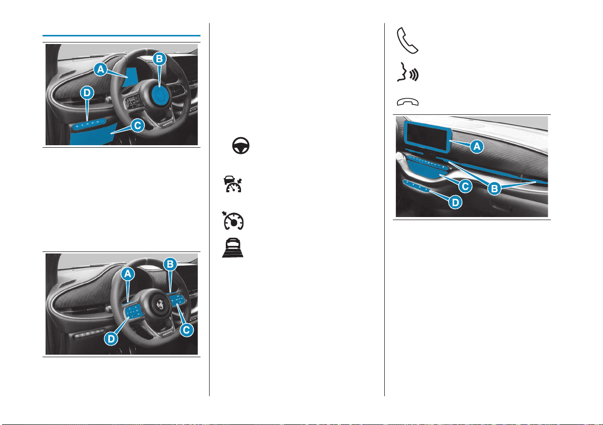
(A) LEFT STALK (Exterior lights)
REAR STEERING WHEEL
CONTROLS, LEFT-HAND SIDE–
Upper/lower button: search tracks/
stations– Middle button: select source
(B) RIGHT STALK (windscreen wiper and
rear window wiper)
REAR STEERING WHEEL
CONTROLS, RIGHT-HAND SIDE–
Upper/lower button: volume up/
down– Middle button: Mute on/off
Answer call
Voice controls/interaction with
Apple CarPlay and Android
Auto
Reject/end call
1 AB0A0590
(A) DASHBOARD AND INSTRUMENT
PANEL
(B) HORN/AIRBAG
(C) FUSES IN DASHBOARD
(D) CONTROLS: Parking sensor
activation/deactivation, ESC
activation/deactivation, Rear fog light,
Headlight height adjustment.
2 AB0A0591
4
(C) TJA (Traffic Jam Assist)
activation/deactivation
ACC (Adaptive Cruise
Control) activation/
deactivation
CC (Cruise Control)
activation/deactivation
ACC distance adjustment
LIM SL (Speed Limiter) and ISA
(Intelligent Speed Assist)
activation/deactivation
SET +/- CC, ACC, SL, ISA speed
increase/decrease
CANC CC, ACC, SL, ISA
deactivation
RES CC, ACC, SL, ISA speed
reset
(D) PHONE CONTROLS
3 AB0A0592
(A) Uconnect™
(B) AIR VENTS
(C) CLIMATE CONTROL SYSTEM,
USB DATA PORT AND WIRELESS
CHARGING DEVICE
(D) ONE-SPEED GEARBOX
Page 6
MANUAL/AUTOMATIC
CLIMATE CONTROL
SYSTEM
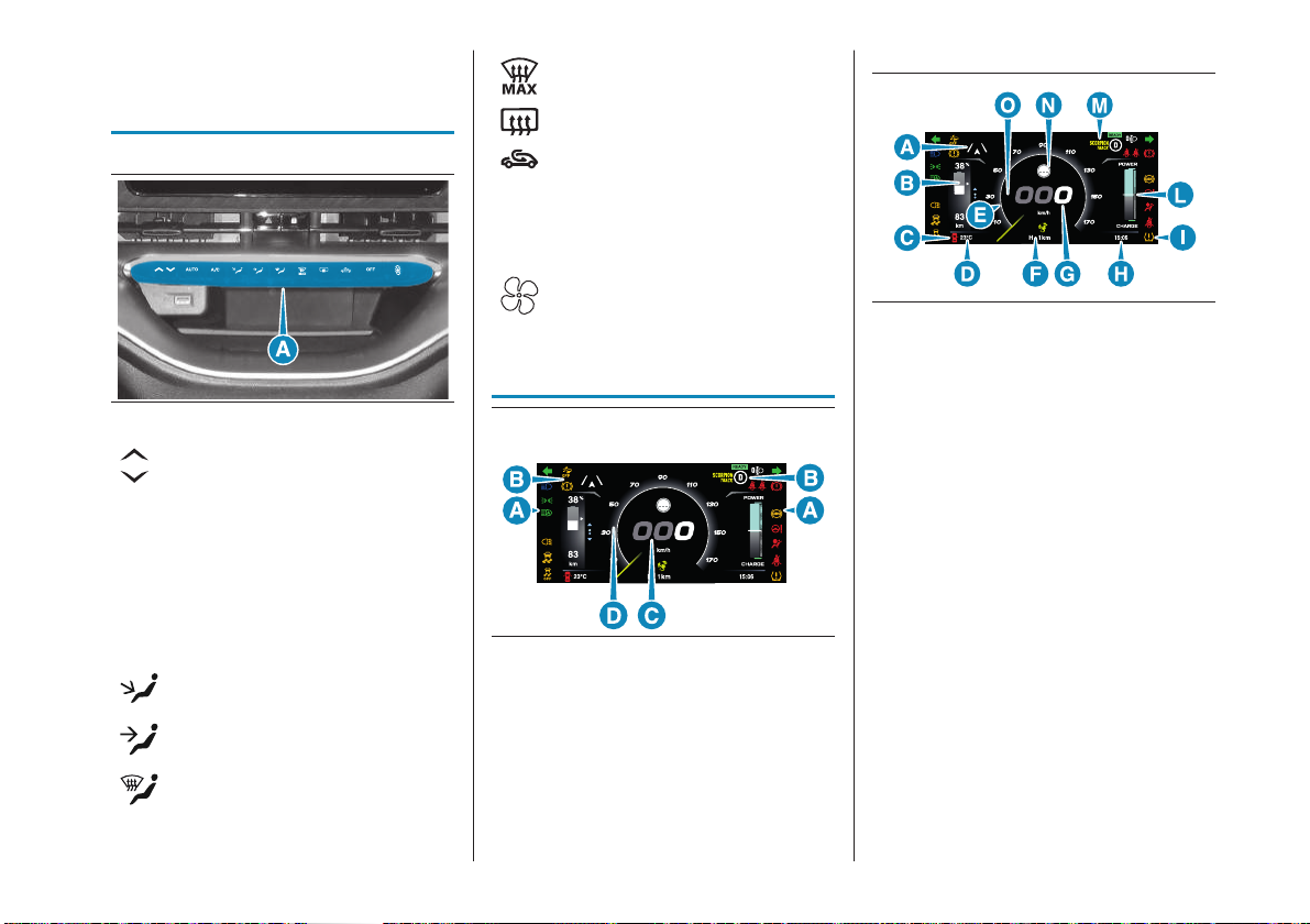
quick window defrosting/
demisting
heated rear window
DISPLAY
(A) fig.4
4 AB0A0593
increase/decrease in input air
temperature
AUTO AUTO function activation
(automatic operation- only
for versions with automatic
climate control system)
A/C climate control system
compressor activation/
deactivation
air to front and rear footwell
selector
air to body selector
window demisting/defrosting
selector
internal air recirculation
OFF climate control system on/
off (only for versions with
automatic climate control
system)
fan speed adjustment
INSTRUMENT
PANEL FEATURES
5 AB0A0595
(A) Warning lights
(B) Engaged gear, headlamp alignment,
seat belt status, driver assist and
active safety systems notification area
(C) Speedometer
(D) Multi-function circular indicator: speed
indication
6 AB0A0594
(A) Driving assistance and active safety
system notifications
(B) High-voltage battery charge state of
charge and range
(C) Failure icons
(D) External temperature
(E) Multi-function circular indicator: speed
indicator
(F) Odometer
(G) Speedometer
(H) Time
(I) Amber notification or failure indication
icons
(L) Energy management
(M) Driving modes
(N) TSR and ISA system indication (where
provided)
(O) Cruise Control/ Adaptive Cruise
Control/ Speed Limiter/ Intelligent
Speed Assist target speed setting
(where provided)
5
Page 7
SOUND GENERATOR
(where provided)
Sound Generator is an innovative system
that recalls the classic Abarth roar, making
it even more powerful and iconic.
It can be activated and deactivated from
the instrument panel settings under the
menu "Display" > "Electric Vehicle" >
"Exterior Sound".
The setting menu is only available when
the vehicle is below 5 km/h or stationary.
If the Sound Generator is deactivated, the
audible warning system for pedestrians
remains active below 25 km/h and sounds
to warn pedestrians of the car's approach
are provided by a speaker in the engine
compartment.
WARNING LIGHTS
AND MESSAGES
WARNING The warning light switches on
in the instrument panel together with a
dedicated message and/or chime when
applicable. These indications are indicative
and precautionary and as such must
not be considered as exhaustive and/or
alternative to the information contained in
the online Owner Handbook, which you
are advised to read carefully in all cases.
Always refer to the information in this
section in the event of a failure indication.
IMPORTANT Causes of ignition and
actions to be taken are illustrated in detail
in the online Owner Handbook. However,
the following actions are briefly outlined in
this Quick Guide:
(*) Contact a Dealership
(**) Repair immediately using the dedicated
“Fix&Go” kit and contact a Dealership as
soon as possible
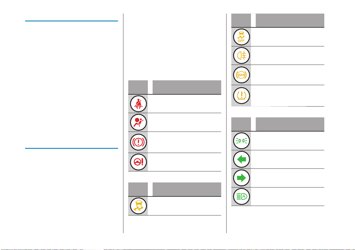
RED WARNING LIGHTS
Warning
light
SEAT BELTS REMINDER
AIRBAG FAILURE (*)
ELECTRIC PARKING BRAKE
FAILURE (*)/ LOW BRAKE
FLUID (*)/ ELECTRIC PARKING
BRAKE APPLIED
ELECTRIC POWER STEERING
FAILURE (*)
Meaning
AMBER WARNING LIGHTS
Warning
light
ESC SYSTEM INTERVENTION/
ESC SYSTEM FAILURE (*)/
HILL HOLDER FAILURE (*)
Meaning
Warning
light
ACTIVE SAFETY SYSTEM
PARTIAL OR TOTAL
DEACTIVATION
REAR FOG LIGHT
ABS FAILURE (*)
LOW TYRE PRESSURE/
iTPMS FAILURE (*)/
iTPMSTEMPORARILY
DEACTIVATED (**)
Meaning
GREEN WARNING LIGHTS
Warning
light
SIDE LIGHTS AND DIPPED
BEAM HEADLIGHTS/FOLLOW
ME HOME
LEFT DIRECTION INDICATOR
RIGHT DIRECTION INDICATOR
AUTOMATIC MAIN BEAM
HEADLIGHTS
Meaning
6
Page 8
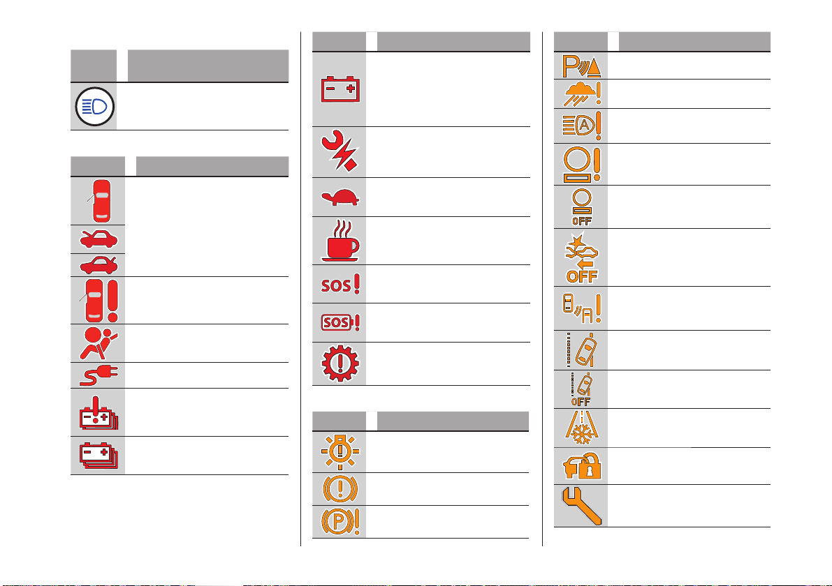
BLUE WARNING LIGHTS
Warning
light
MAIN BEAM HEADLIGHTS
Meaning
RED SYMBOLS
Symbol Meaning
DOORS/ BONNET/ BOOT
OPEN
DOOR FAILURE (*)
AIRBAG FAILURE (*)
VEHICLE CHARGING
PROCEDURE FAILURE (*)
HIGH-VOLTAGE BATTERY
FAILURE (*)
LOW HIGH-VOLTAGE
BATTERY CHARGE (*)
Symbol Meaning
12V BATTERY CHARGING
CONDITIONS (*)/ DC-DC
CONVERTER FAILURE(*)/
LOGISTICS MODE
ACTIVATED/ POWER
SUPPLY MODE
ELECTRIC SYSTEM
FAILURE(*)
PERFORMANCE LIMITATION
ATTENTION ASSIST SYSTEM
INTERVENTION
EU eCall SYSTEM FAILURE (*)
EU eCall SYSTEM BATTERY
FAILURE (*)
TRANSMISSION FAILURE (*)
AMBER SYMBOLS
Symbol Meaning
EXTERNAL LIGHTS FAILURE
BRAKE FAILURE (*)
ELECTRIC PARKING BRAKE
FAILURE (*)
Symbol Meaning
PARKING SENSOR FAILURE
RAIN SENSOR FAILURE (*)
AUTOMATIC MAIN BEAM
HEADLIGHTS FAILURE (*)
TRAFFIC SIGN
RECOGNITION SYSTEM
FAILURE (*) (where provided)
TRAFFIC SIGN
RECOGNITION SYSTEM OFF
(where provided)
AUTONOMOUS EMERGENCY
BRAKE CONTROL (AEB)
SYSTEM DEACTIVATION
BLIND SPOT ASSIST
FAILURE (*)
LANE CONTROL FAILURE (*)
LANE CONTROL
DEACTIVATION
POSSIBLE ICE ON ROAD
FIAT CODE SYSTEM
FAILURE(*)/ BREAK-IN
ATTEMPT
SERVICE (SCHEDULED
SERVICING) EXPIRED
7
Page 9
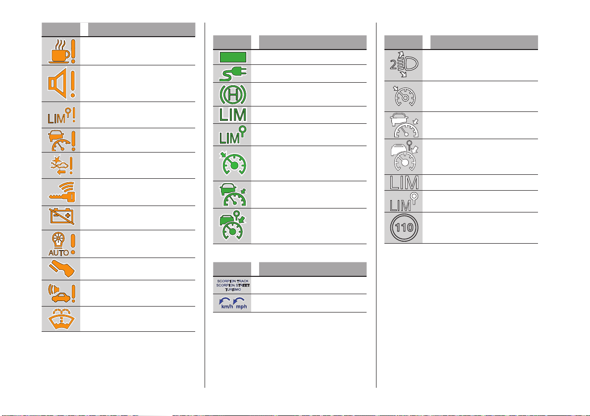
Symbol Meaning
ATTENTION ASSIST SYSTEM
FAILURE (*)
SOUND SYSTEM FAILURE
INTELLIGENT SPEED
ASSIST/ SPEED LIMITER
FAILURE (*)
ADAPTIVE CRUISE CONTROL
(ACC) FAILURE (*)
AUTONOMOUS EMERGENCY
BRAKE CONTROL (AEB)
SYSTEM FAILURE (*)
KEYLESS ENTER-N-GO
SYSTEM FAILURE
HIGH-VOLTAGE BATTERY
DISCONNECTED (*)
DUSK SENSOR FAILURE (*)
PRESS THE BRAKE PEDAL
PEDESTRIAN ACOUSTIC
WARNING SYSTEM
FAILURE(*)
LOW WINDSCREEN
WASHER LEVEL
GREEN SYMBOLS
Symbol Meaning
READY
SYSTEM READY
CHARGING CABLE
CONNECTED
HOLD ‘N’ GO
SPEED LIMITER ON
INTELLIGENT SPEED ASSIST
SYSTEM ON
ELECTRONIC CRUISE
CONTROL ON
ADAPTIVE CRUISE CONTROL
ACTIVATION
INTELLIGENT ADAPTIVE
CRUISE CONTROL
ACTIVATION
BLUE SYMBOLS
Symbol Meaning
DRIVING MODES
SPEED LIMIT EXCEEDED
WHITE SYMBOLS
Symbol Meaning
HEADLIGHT HEIGHT
ELECTRONIC CRUISE
CONTROL READY
ADAPTIVE CRUISE CONTROL
READY
INTELLIGENT ADAPTIVE
CRUISE CONTROL READY
SPEED LIMITER READY
INTELLIGENT SPEED
LIMITER READY
SPEED LIMIT EXCEEDED
8
Page 10
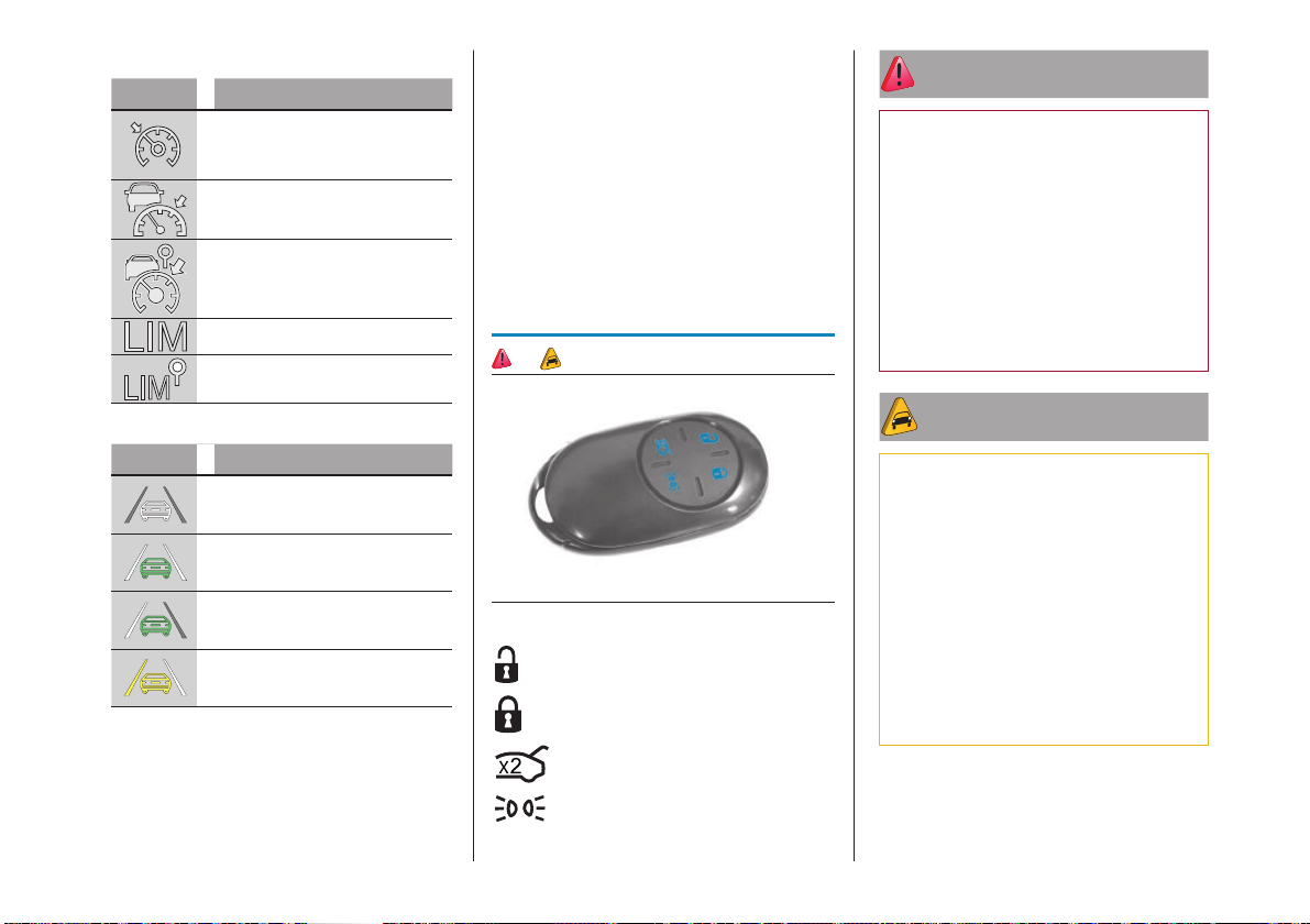
GREY SYMBOLS
Symbol Meaning
ELECTRONIC CRUISE
CONTROL ON
ADAPTIVE CRUISE
CONTROL ON
INTELLIGENT ADAPTIVE
CRUISE CONTROL ON
SPEED LIMITER ON
INTELLIGENT SPEED ASSIST
ON
LANE CONTROL SYMBOLS
Symbol Meaning
SENSOR NOT AVAILABLE
SYSTEM ON
SYSTEM ON (only one side
line detected)
CAR CLOSE TO THE SIDE
LINE
DISPLAY FAILURE
All the warning lights flash in the event of
an instrument panel display failure.
CONTROL SYSTEM
WARNING LIGHT FAILURE
The failure of the control system warning
light is indicated by a message on the
instrument panel display.
LANE CONTROL
SYSTEM DISABLED OR
MALFUNCTIONING
If the warning appears with the system
enabled, contact a Dealership.
KEYS
1) 1) 2) 3)
7 F0S1229
Door unlocking
Door locking
Two quick presses: luggage
compartment opening
Lights on
ATTENTION
1) Do not swallow the battery. Danger
of chemical burns. The keys contain a
small battery. If the battery is swallowed,
it can cause severe internal burns in just
2 hours and cause death. Keep new
and used batteries out of the reach of
children. If the battery compartment
does not close securely, discontinue use
of the product and keep it out of reach
of children. If you believe that batteries
may have been swallowed or inserted
inside the body, seek medical attention
immediately.
WARNING
1) The electronic components inside
the key may be damaged if the key is
subjected to strong shocks. In order
to ensure complete efficiency of the
electronic devices inside the key, it
should never be exposed to direct
sunlight.
2) Do not place the car keys in the
wireless charging compartment (C)
fig.3: risk of access and starting system
malfunction.
3) Do not place contactless cards (RFID),
credit cards or metal objects in the
charging compartment.
9
Page 11
DOORS
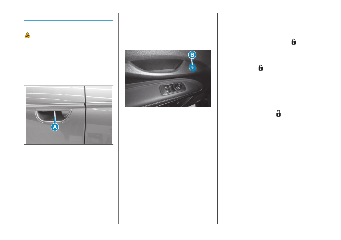
PASSIVE ENTRY
4)
If the system identifies the electronic
key detected outside the car as a valid
one, the key holder can simply pull the
handle (A)fig.8 on the driver side door to
deactivate the alarm and open the door.
The other doors and the boot will be
unlocked.
8 F0S1260
LOCKING/ UNLOCKING
DOORS FROM THE INSIDE
Opening the door
The door can be opened by pressing the
button (B)fig.9 located above each door.
If the function is present, pressing the
button on either door opens the door and
unlocks the other doors and the boot.
The function must have been activated via
the instrument panel display menu or the
Uconnect™ system.
9 AB0A0513
Press button (B) three times in two
seconds to open the door in motion
at speeds above 5km/h (to prevent
spontaneous opening of the door while in
motion).
At speeds below 5km/h, the door will
open when the button is pressed for the
first time. The red LED around the button
will light up when the door is locked and it
will turn off when the door is unlocked.
LOCKING/ UNLOCKING
DOORS FROM
THE OUTSIDE
Locking from the outside
With the doors closed, press the button
on the key.
The door lock can be activated also with
all doors open and the boot open.
When the button
on the key is pressed,
all the locks are closed, including that of
the open boot. When the open door or
boot is closed, it will be locked and cannot
be opened from outside any more.
Door unlocking from the
outside
Press the opening button on the key.
Then pull the handle (A)fig.8 on one of
the two doors to enter the car.
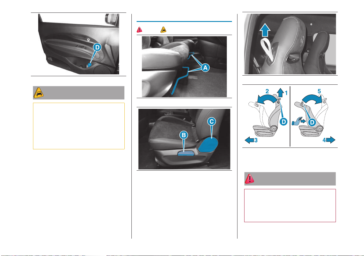
Emergency opening of the
doors from the inside
If the electronic key does not work,
for example if the electronic key or the
12Vbattery of the car is low, the doors
can still be opened from the inside by
pulling the emergency lever (D)fig.10
located on each door.
10
Page 12
SEATS
2) 3) 4) 5)
10 AB0A0514
WARNING
4) Key recognition depends on various
factors, such as electromagnetic
interference emitted by external sources
(e.g. mobile phones), the charge state
of the key battery, and the presence of
metal near the key or car. In such cases,
the doors can be unlocked with the
metal insert inside the key.
11 AB0A0556
12 AB0A0581
Lift lever (A): longitudinal adjustment
Raise/lower lever (B): height
adjustment
Turn lever (C): tilt adjustment
13 AB0A0603
14 AB0A0557
Act on the fig.13 tie indicated with (D)
fig.14: backrest tilt
ATTENTION
2) All adjustments must be made with
the car stationary and engine stopped.
3) If a side bag is fitted, it is dangerous
to use seat covers not available from
Lineaccessori MOPAR®.
11
Page 13
4) After releasing the adjustment lever,
always check that the seat is locked on
the guides by trying to move it back and
forth. If the seat is not locked into place,
it may unexpectedly slide and cause the
driver to lose control of the car.
WARNING
5) The fabric upholstery of the seats has
been designed to withstand long-term
wear deriving from normal use of the car.
Some precautions are however required.
Avoid prolonged and/or excessive
rubbing against clothing accessories
such as metal buckles and Velcro strips
which, by applying a high pressure on
the fabric in a small area, could cause
it to break, thereby damaging the
upholstery.
IGNITION DEVICE
5) 6) 7) 8) 9)
15 AB0A0604
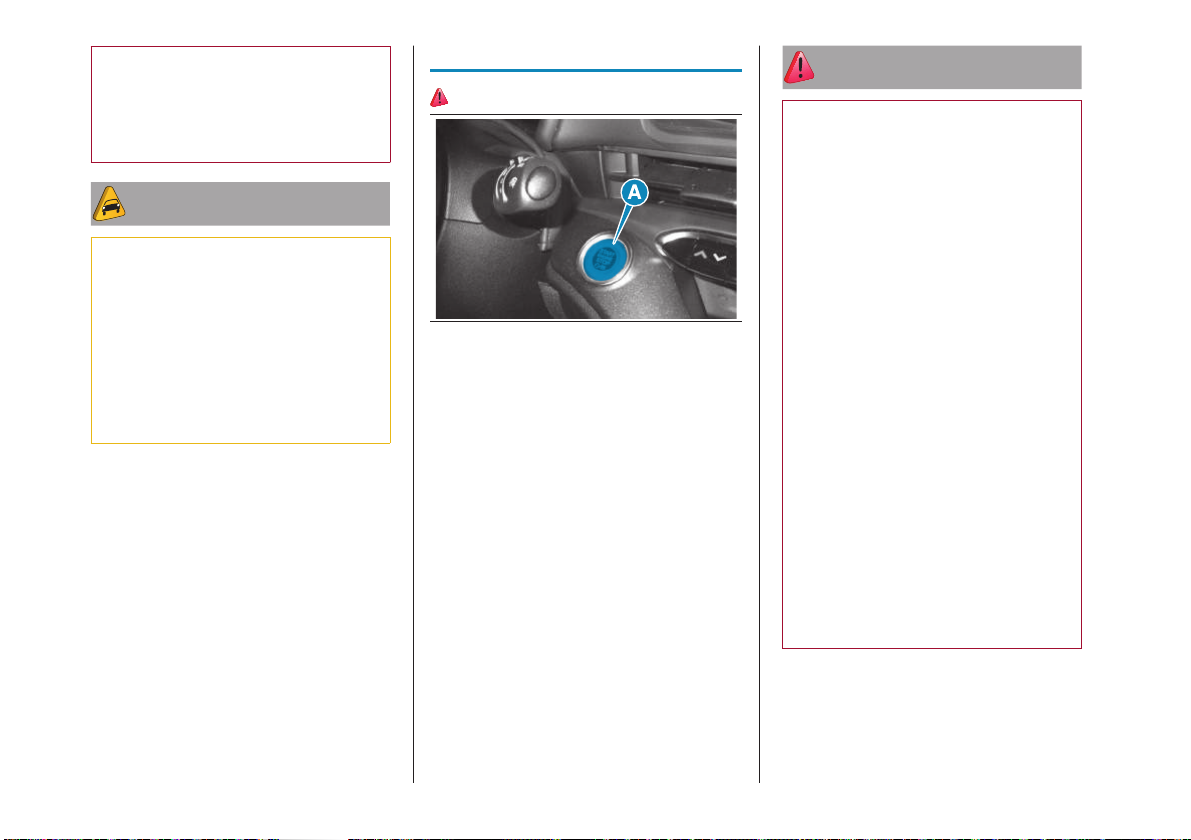
STOP: the motor is off. Some electrical
devices (e.g. central door locking
system, alarm, etc.) are still available
ENGINE: driving position. All electrical
devices are available. This state can
be selected by pressing the ignition
device button once, without pressing
the brake pedal
START: motor starting
ATTENTION
5) It is absolutely forbidden to carry out
any after-market operation involving
steering system or steering column
modifications (e.g. installation of antitheft device) that could adversely affect
performance and safety, invalidate
the warranty and also result in noncompliance of the car with type-approval
requirements.
6) If the ignition device has been
tampered with (e.g. an attempted theft),
have it checked over by a Dealership
before driving again.
7) Always take the key with you when
you leave your car to prevent someone
from accidentally operating the controls.
Remember to engage the electric
parking brake. Never leave children
unattended in the car.
8) Before leaving the car, ALWAYS
engage the electric parking brake. Put
the transmission in the P (Park) position
and press the ignition device to set it to
STOP. Always lock the doors when you
leave the car.
9) Do not leave the electronic key inside
or near the car or in a place accessible
to children.
Do not leave the car with the ignition
device in the ENGINE position. A child
could activate the electric window
winders, other controls or even start the
car.
12
Page 14
ENGINE STARTING
10)
The gearbox must be in position P or N.
Proceed as follows:
fully depress the brake pedal without
touching the accelerator
press the ignition device to take it
to the START position. Hold it fully
depressed for a couple of seconds
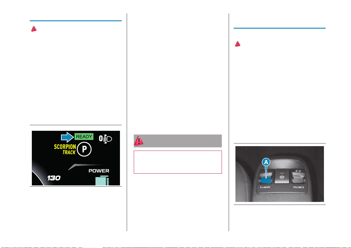
At the end of the procedure, a chime will
be heard and the message "READY" will
appear on the instrument panel display
(see fig.16) to indicate that the electric
traction system of the Abarth 500e has
started. When the "READY" message
appears, the Abarth 500e is ready to go.
IMPORTANT If there is a starting request
with the transmission in a position other
than P or N and without the brake pedal
pressed, the display will show a dedicated
message (see the "Warning lights and
messages" paragraph). In this case,
repeat the starting manoeuvre, pressing
the brake pedal.
IMPORTANT If starting is requested with a
transmission failure (see "TRANSMISSION
FAILURE" in the "Warning lights and
messages" section), carry out the
“Delayed start-up” procedure. The motor
will be started when the ignition device is
turned to START for at least 7 seconds
with brake pedal pressed.
The system will remain in “recovery”
condition. If the engine does not start,
contact a Dealership.
ATTENTION
10) The brake servo is not active until the
engine is started, so you would need to
apply much more force than usual to the
brake pedal.
OPERATING
PRINCIPLE
OPERATING MODE
11) 12) 13)
While driving, you can activate the
selector (A)fig.17 located on the central
tunnel. This device allows you to set
three different driving modes according
to the driver's needs:
SCORPION TRACK
SCORPION STREET
TURISMO
Via the on board electronics, the device
acts on the dynamic control system of the
car (motor, ESC system), interfacing the
instrument panel as well. The selector is
of "hold to operate" type, returning to the
central position when released.
16 AB0A0537
IMPORTANT If the "READY" message
does not appear on the instrument panel
despite the correct start-up procedure,
contact a Dealership.
17 AB0A0490
13
Page 15

“SCORPION TRACK” MODE
In the "SCORPION TRACK" operating
mode, the car has no performance
limitations and can be driven fast using
all the power and torque of the traction
system. In this mode, the energy
consumption of the car depends on the
driving style.
In "SCORPION TRACK" mode, when
the accelerator pedal is released, the car
slows down with an engine braking effect
similar to that of a conventional vehicle.
During this phase, the high-voltage battery
is partially recharged (regeneration).
The "creeping" function is also available.
The car will start to move forward (with
gearbox in "D") or backward (with gearbox
in "R") when the brake pedal is released.
The accelerator should not be pressed in
this case.
“SCORPION
STREET” MODE
By selecting the "SCORPION STREET"
mode, the car has no performance
limitations but offers a sporty drive,
utilising all the power and torque of the
drive system.
WARNING The "SCORPION STREET"
function is enabled on the accelerator
pedal in "RANGE" mode. In this case,
the car can be accelerated, decelerated
and stopped by acting only on the
accelerator pedal. See the "One-Pedal
Driving" chapter. This mode tends to
maximise energy recovery during vehicle
deceleration.
The "creeping" function is deactivated in
this mode.
“TURISMO“ MODE
When the "TURISMO" mode is selected,
the vehicle's acceleration and top
speed characteristics are optimised for
a more comfortable and efficient driving
experience. Top speed is electronically
limited to 150 km/h.
The "creeping" function is deactivated in
this mode.
WARNING The "One-Pedal Driving"
function is enabled on the accelerator
pedal in "TURISMO" mode. In this case,
the car can be accelerated, decelerated
and stopped by acting only on the
accelerator pedal.
PERFORMANCE
LIMITATION"TURTLE" MODE
"Turtle" mode is activated automatically
when the remaining range is less than
24km, but can be temporarily deactivated
(for example to clear a junction) by quickly
depressing the accelerator pedal fully
(kick-down function).
Range: 24-16km
Amber high-voltage battery charge
status indicator, symbol on
the instrument panel display lit for
6seconds
Speed according to selected mode
(SCORPION TRACK, SCORPION
STREET, TURISMO)
The heated rear window, windscreen,
mirrors and seats are deactivated
automatically (but can be reactivated
manually if necessary)
14
Page 16

Range: 16-8km
Red high-voltage battery charge
status indicator, symbol on the
instrument panel display lit fixed
Speed according to selected mode
(SCORPION TRACK, SCORPION
STREET, TURISMO)
The heated rear window, windscreen,
mirrors and seats are deactivated
automatically (but can be reactivated
manually if necessary)
Range: 8-0km
Red high-voltage battery charge
status indicator, symbol on the
instrument panel display lit fixed
Top speed: 70 km/h
The climate control system is
deactivated, and the fan and quick
defrosting may be activated. The
heated rear window, windscreen,
mirrors and seats are deactivated
automatically (but can be reactivated
manually if necessary).
Range: ≈0km (emergency
conditions)
Red high-voltage battery charge
status indicator, symbol on the
instrument panel display blinking.
Top speed: 70 km/h
The climate control system is
deactivated, and the fan and quick
defrosting may be activated. The
heated rear window, windscreen,
mirrors and seats are deactivated
automatically (but can be reactivated
manually if necessary).
NOTE "Turtle" mode speed limits are
disabled when Speed Limiter, Intelligent
Speed Assist, Adaptive Cruise Control,
Intelligent Adaptive Cruise Control and
Cruise Control are active.
NOTE Some climate control system
functions may be unavailable in “Turtle”
mode, in which case the LEDs on the
climate control system controls will flash.
ATTENTION
11) Under no circumstances may the
motor brake replace pressing the brake
pedal.
12) In case of bad weather and flooded
roads: Do not drive on a flooded street if
the water level exceeds the lower part of
the wheel rims.
13) Due to the quiet operation of your
electric car, always set the speed
selector to P and engage the electric
parking brake before leaving it.
ONE-PEDAL DRIVING
With One-Pedal Driving in "SCORPION
STREET" and "TURISMO" modes, the
accelerator pedal can also be used
to control deceleration of the car to a
complete stop.
Quickly release the accelerator pedal to
obtain aggressive deceleration. Slowly
release the accelerator pedal to adjust of
the deceleration of the car.
WARNING When One-Pedal Driving is
active and the driver releases the seat
belt, the electric parking brake is applied
automatically and One-Pedal Driving is not
possible.
Press the accelerator pedal to reach the
desired speed.
15
Page 17
The deceleration provided by One-Pedal
Driving mode allows for full regenerative
braking and helps to increase the
efficiency of the car.
With the One-Pedal Driving mode
enabled, the electric parking brake may
be automatically applied if:
the car stops on a slope
the driver’s door is open
car stopped for longer than five
minutes
problem to the propulsion system
To resume driving, press the accelerator
pedal and the electric parking brake will
automatically release. The One-Pedal
Driving mode may shift the transmission to
P if the car is pushed after stopping or if
there is a problem with the electric motor.
ONE-SPEED
GEARBOX
Abarth 500e uses a one-speed
transmission operated by buttons instead
of the traditional gear lever.
The buttons (D)fig.3 are located on the
lower dashboard.
6)
NOTE If all button LEDs are lit when the
ignition device is in the ENGINE position,
contact a Dealership.
14) 15) 16) 17) 18)
ATTENTION
14) Only engage a gear while keeping
the brake pedal fully pressed.
15) The unexpected movement of the
car could injure the occupants or people
nearby. As a general rule, do not get out
of the car when it is in "READY" mode.
Before leaving the car, always apply the
electric parking brake, put the gearbox
in the P (Park) position and remove the
ignition key. Once the key is removed,
the gearbox remains locked in position P
(Parking), thus preventing any accidental
movement of the car.
16) When you get out of the car, always
remove the ignition key and lock all the
doors.
17) NEVER leave children unattended
inside the car, let alone leave the car
with the doors unlocked in a place that
children can access easily. Children
may seriously, or even fatally, injure
themselves. Also ensure that children
do not inadvertently operate the electric
parking brake, the brake pedal or the
transmission button.
18) Do not leave the electronic key inside
or near the car (or in a place accessible
to children). A child could activate the
electric window winders, other controls
or even start the car.
WARNING
6) Failure to observe the following
precautions can have serious
consequences for the gearbox. Put the
gearbox in the P (Park) position only
when the car is completely stationary;
engage R (Reverse) or disengage only
when the car is completely stationary.
Keep the brake pedal fully pressed
before engaging any gear.
16
Page 18
INTERIOR FITTINGS
19) 20)
ATTENTION
19) Do not travel with the storage
compartments open: they may injure the
front seat occupants in the event of an
accident.
20) With the vehicle in motion, the
smartphone may only be used in
the upright position and only with
the ABARTH Link & Drive App. The
smartphone may be placed in a
horizontal position only when the vehicle
is stationary. Avoid distractions while
driving by using the smartphone Always
follow the highway code of the country in
which you are driving, and concentrate
on the road. Always drive safely with
your hands on the steering wheel. Only
use the functions of the system and
the ABARTH Link & Drive Apps when
you are sure that it is safe to do so. The
customer is liable for all risks associated
with using the functions and applications
of the car. Failure to follow these rules
may cause serious accidents and/or
death.
EXTERNAL LIGHTS
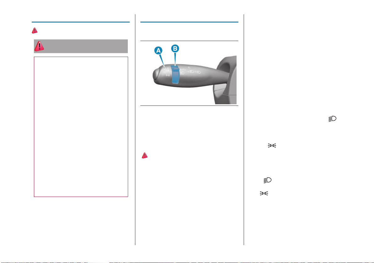
The left stalk (A)fig.18 operates most of
the exterior lights.
18 F0S1111
The exterior lights can only be switched on
when the ignition device is in the ENGINE
position.
DAYTIME RUNNING
LIGHTS (DRL)
21) 22)
The daytime running lights (DRL) are
activated with the ring (B)fig.18 in the
AUTO position and in daylight conditions.
The first time the ignition is switched on,
they remain off as long as the electric
parking brake (EPB) is engaged or the
gearbox is in the P (Parking) position.
AUTOMATIC LIGHTING
CONTROL (AUTOLIGHT)–
DUSK SENSOR
Activation
With the ignition device in the ENGINE
position, turn the ring (B)fig.18 to
the AUTO position to activate the
"Automatic lighting control" function. This
automatically switches on the side/tail
lights and dipped-beam headlights in case
of low external light or DRL in daytime
driving conditions.
DIPPED BEAM
HEADLIGHTS
With the ignition device in the ENGINE
position, turn the ring (B)fig.18 to .
If dipped headlights are activated, the
daytime running lights switch off and the
side lights and dipped headlights switch
on. The warning light switches on in
the instrument panel.
PARKING LIGHTS
With the ignition device turned to STOP,
turning the ring (B) from the AUTO position
to the position will light up the side/
tail lights and number plate lights. Warning
light lights up on the instrument panel.
17
Page 19
AUTOMATIC MAIN
BEAM HEADLIGHTS
This function is enabled with the
Uconnect™ system and with the light
switch (B)fig.18 turned to the AUTO
position. The first time the main beam
headlights are activated (pushing the left
stalk towards the dashboard), the function
is activated (warning light comes on in
the instrument panel).
If the main beam headlights are actually
on, the warning light
will also come
on in the instrument panel.
When the speed is higher than 40km/h
and the function is active, the lights switch
off if the lever is taken again to the stable
central position.
When the speed is lower than 15km/h
and the function is active, the function
switches the main beam headlights off.
DIRECTION INDICATORS
Take the left stalk to the (stable)
position:
upwards: activates right direction
indicator
downwards: activates the left direction
indicator
Warning light
or will blink on the
instrument panel. The direction indicators
are switched off automatically when the
steering wheel is straightened.
"Lane change" function
If you wish to signal a lane change, place
the left stalk in the unstable position for
less than half a second.
The direction indicator on the side
selected will be activated for 5 flashes and
then go out automatically.
HEADLIGHT ALIGNMENT
ADJUSTMENT
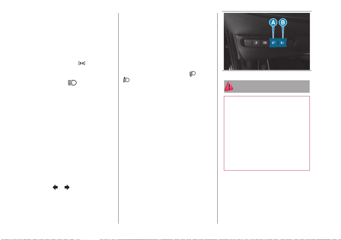
To adjust, press the buttons (A) or (B)
fig.19 on the control display located
on the left side of the dashboard (left hand
drive versions).
The adjustment position is shown on
the display:
Position 0: one or two people in the
front seats
Position 1: 4 people
Position 2: 4 people + load in luggage
compartment
Position 3: driver + maximum
admissible load stowed only in the
luggage compartment.
19 AB0A0518
ATTENTION
21) The daytime running lights are an
alternative to the dipped headlights for
driving during the daytime in countries
where it is compulsory to have lights
on during the day; where it is not
compulsory, the use of daytime running
lights is permitted.
22) Daytime running lights cannot
replace dipped beam headlights when
driving at night or through tunnels. The
use of daytime running lights is governed
by the highway code of the country in
which you are driving. Comply with legal
requirements.
18
Page 20
DRIVING ASSISTANCE
SYSTEMS
23) 7) 8) 9) 10) 11) 12)
ATTENTION
23) These systems are an aid for the
driver, who must always pay full attention
while driving. The responsibility always
rests with the driver, who must take into
account the traffic conditions in order to
drive in complete safety. The driver must
always maintain a safe distance from the
vehicle in front.
WARNING
7) The systems may have limited
or absent operation due to weather
conditions such as low sun, heavy rain,
hail, thick fog, or heavy snow, formation
of ice layers on the windscreen glass.
8) Systems intervention might be
unexpected or delayed when other cars
transport loads projecting from the side,
above or from the rear, with respect to
the normal size of the car.
9) Operations can be adversely affected
by any structural change made to the
car, such as a modification to the front
geometry, tyre change, or a heavier load
than the standard load of the car.
10) Incorrect repairs in the zone where
the camera is mounted may interfere
with its field of vision and reduce its
performance (e.g. application of fillers
or glues to remove scratches). Go to a
Dealership for any operation of this type.
11) Do not tamper with nor operate
on the camera on the windscreen. In
the event of a sensor failure, contact a
Dealership.
12) Camera operation may also be
compromised by the presence of
dust, condensation, dirt or ice on the
windscreen glass, by traffic conditions
(e.g. cars that are driving not aligned
with yours, car driving in a transverse or
opposite way on the same lane, bend
with a small radius of curvature), by
road surface conditions and by driving
conditions (e.g. off-road driving). Make
sure the windscreen is always clean. Use
specific detergents and clean cloths to
avoid scratching the windscreen. The
camera operation may also be limited or
absent in some driving, traffic and road
surface conditions.
WHEN PARKED
24) 25) 26)
With your foot on the brake pedal, put
the transmission to position P and, if
you are on a sloping road, leave the
wheels steered. Before releasing the
brake pedal, wait until P appears on
the display.
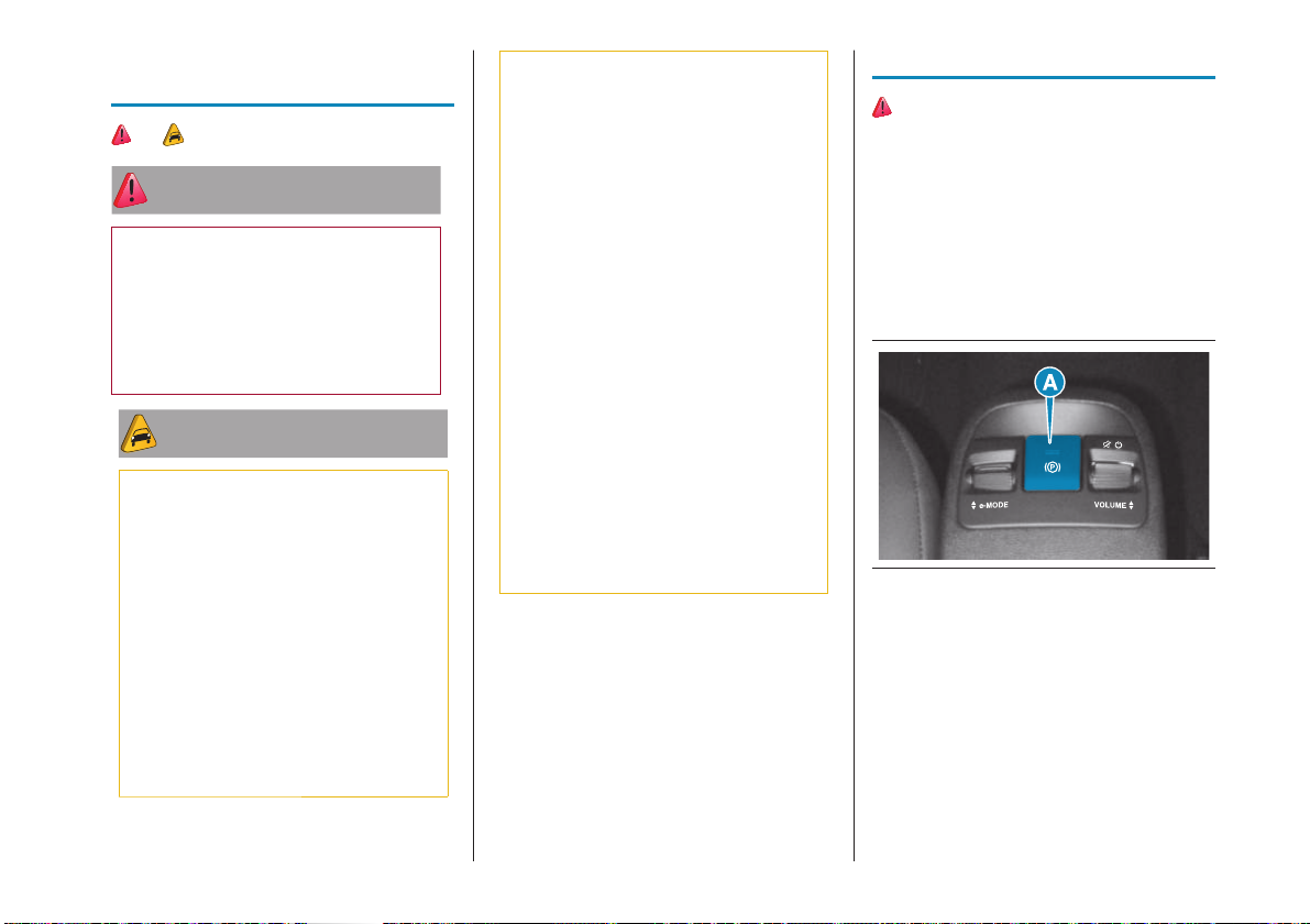
Engage the electric parking brake
(EPB) by pulling the lever (A) fig.20
and stop the engine
20 AB0A0492
Block the wheels with a wedge or a stone
if the car is parked on a steep slope. Do
not leave the ignition device in the ENGINE
position to prevent running down the
12Vbattery.
IMPORTANT NEVER leave the car before
having put the transmission in P.
19
Page 21
ATTENTION
24) In the case of parking manoeuvres
on roads on a gradient, the front wheels
must be steered towards the pavement
(when parking downhill), or in the
opposite direction if the vehicle is parked
uphill. Block the wheels with a wedge or
a stone if the car is parked on a steep
slope.
25) Never leave children alone in an
unattended car; make sure that when
you move away from the car, you have
the electronic key with you.
26) The electric parking brake must
always be engaged when leaving the car.
EMERGENCY
CALL- EU ECALL
The car is equipped with an on-board
assistance function designed to provide
support in the event of accident and/or
emergency (SOS). The emergency call,
also known as "eCall", which is required
by law in the countries of the European
Union (EU eCall) based on the emergency
number 112, can be used to call for help
quickly in dangerous situations.
The eCall EU emergency call activates
the voice call to the Operations Centre
dedicated to emergency calls (112)
with simultaneous activation of the
transmission of the vehicle data and
geo-location. The EU eCall service is a
public service of general interest and free
of charge.
The EU eCall function can be activated:
Automatically, in the event of a major
collision recorded by the device by
means of the presence of sensors
aboard the car.
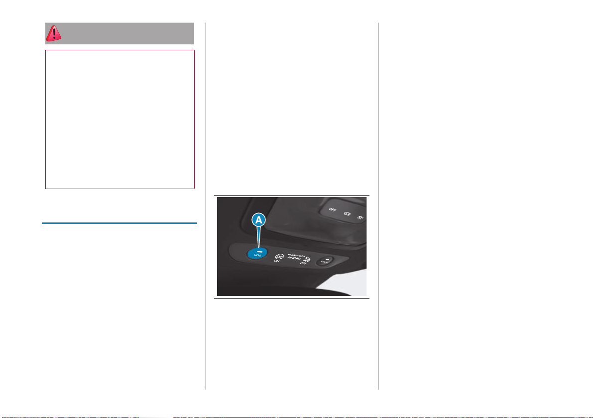
Manually, holding the SOS button
(A) located on the ceiling light fig.21
pressed (for longer than 2 seconds).
21 AB0A0535
After automatic or manual activation by
pressing the SOS button, the function
will send the car data to the Operations
Centre, including the geo-location data of
the data, and a voice call will be initiated
with an operator. If the EU eCall function
does not work, the fault in the system
will be indicated on the instrument panel
display. Go as soon as possible to a
Dealership to have the function repaired.
The EU eCall function is activated with:
the ignition device is in the ENGINE
position
ignition device in the STOP position
In the STOP position, the EU eCall is
available for 10 minutes after the ignition
device is switched from ENGINE to
STOP. This condition is only valid for cars
equipped with SOS call in accordance
with the legal regulations in the countries
where it applies.
Once activated automatically (where
provided) or manually by pressing the
corresponding button, the EU eCall
function will send the position data of the
car to the Operations Centre and stablish
a voice call with an operator.
NOTE If the EU eCall function does
not work, the fault in the system will be
indicated on the display. Go as soon
as possible to a Dealership to have the
function repaired.
20
Page 22
NOTE The correct operation of the EU
eCall function will be guaranteed only by a
good network coverage.
Interrupting a call
If the SOS call button is pressed by
mistake, it is possible to press it again
within 10 seconds to cancel the operation.
After 10 seconds, only the operator of the
Operation Centre can interrupt the call.
If you are able to speak to the operator,
do so through the car audio to provide
additional information about the request
for help.
If the Operations Centre needs to contact
the car again, the system can receive, for
up to 120 minutes from the ending of the
call with the operator, an incoming call,
which will be accepted automatically. Until
the end of 120 minutes, the system will be
completely dedicated to the management
of the emergency in progress, therefore it
will not be able to provide any connectivity
service.
CHILD RESTRAINT
SYSTEMS
27) 28) 29) 30) 31) 32) 33) 34)
For optimal protection in the event of an
impact, all occupants must be seated
and wearing adequate restraint systems,
including newborn and children! This
prescription is compulsory in all EC
countries according to EC Directive
2003/20/EC.
35) 36) 37) 38)
FRONT PASSENGER
AIRBAG AND CHILD
RESTRAINT SYSTEMS
Rearward facing child restraint systems
must NEVER be fitted on the front seat
with an active passenger side bag since
in the event of an impact the airbag
activation may cause fatal injuries to the
transported child.
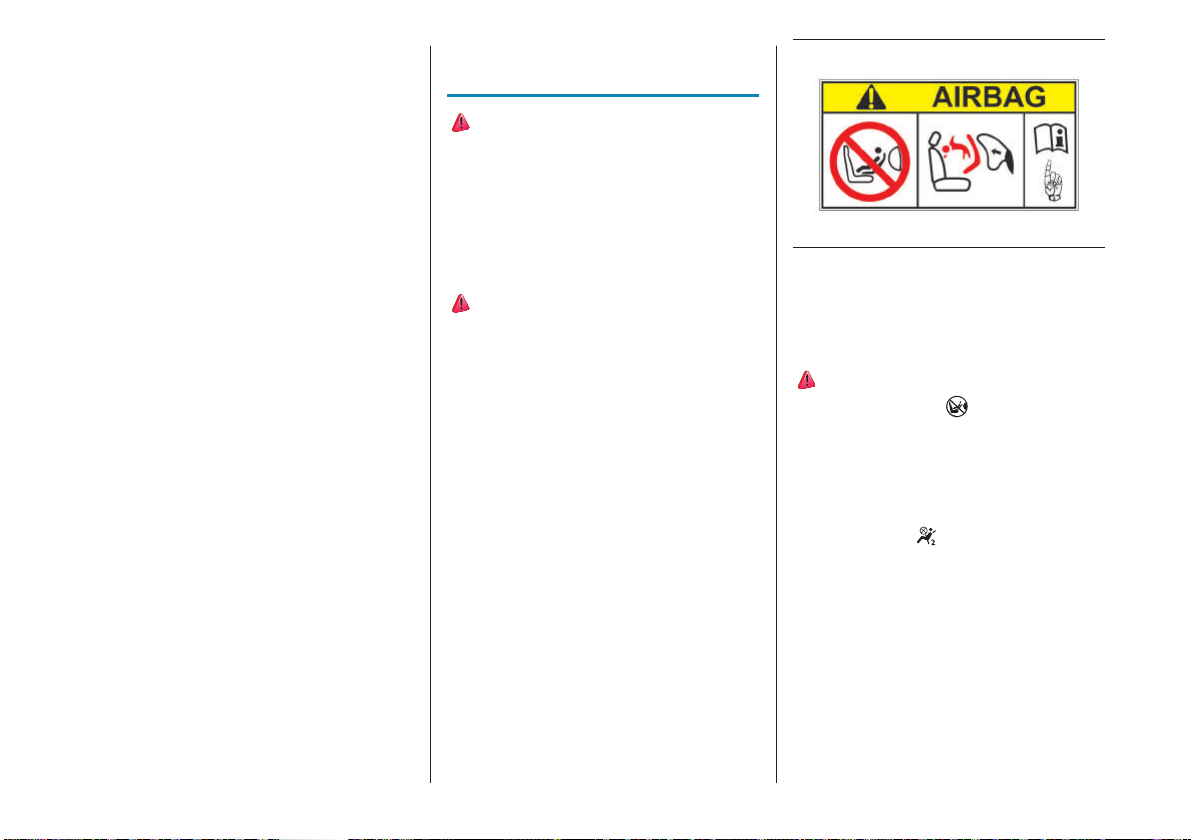
ALWAYS comply with the instructions on
the label stuck on both sides of the sun
visor fig.22.
22 F0S1261
Deactivating the
passenger side airbags:
front airbag and front
side bag
39) 40) 41) 42)
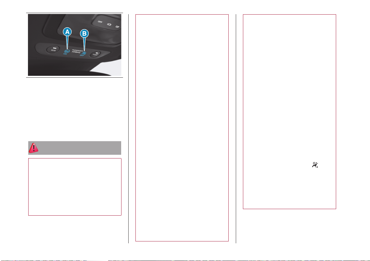
The warning light (A) fig.23 indicates
that the front passenger airbag and front
side bag (where provided) are active.
In this case, it is forbidden to install a
rearward-facing seat on the passenger
seat.
Warning light (B)
fig.23 indicates the
deactivation of the front passenger airbag
and the front side bag (where provided)
and remains lit until they are reactivated.
21
Page 23
23 AB0A0529
WARNING For manual deactivation of
the front passenger airbag and the front
side airbag (where provided), access
the instrument panel menu "Safety"->
"Passenger airbag: enable/disable" using
the steering wheel controls and confirm
the deactivation with the OK button on the
steering wheel.
ATTENTION
27) Incorrect fitting of the child
restraint system may result in an
inefficient protection system. In the
event of an accident the child restraint
system may become loose and the
child may be injured, even fatally.
When fitting a restraint system for
newborns or children, strictly comply
with the instructions provided by the
Manufacturer.
28) When the child restraint system is
not used, secure it with the seat belt or
with the ISOFIX anchorages, or remove
it from the car. Do not leave it unsecured
inside the passenger compartment. In
this way, in the event of sudden braking
or an accident, it will not cause injuries to
the occupants.
29) After installing a child restraint
system, do not move the seat: always
remove the child restraint system before
making any adjustment.
30) If a Universal ISOFIX child restraint
system is not fixed to all three
anchorages, it will not be able to protect
the child correctly. In a crash, the child
could be seriously or fatally injured.
31) Fit the child restraint system when
the car is stationary. The child restraint
system is correctly secured to the
brackets when you hear the click.
Follow the instructions for assembly,
disassembly and positioning that the
Manufacturer must supply with the child
restraint system.
32) Always make sure that the chest
section of the seat belt does not pass
under the arms or behind the back of
the child. In the event of an accident the
seat belt will not be able to secure the
child, with the risk of injury, including fatal
injury. Therefore the child must always
wear the seat belt correctly.
33) Do not use the same lower
anchoring to install more than one child
restraint system.
34) Fit the child restraint system
according to the instructions, which
must be included.
35) SEVERE DANGER! When a
passenger front airbag is fitted, do not
install rearward facing child restraint
systems on the front passenger seat.
Deployment of the airbag in a crash
could cause fatal injuries to the child
regardless of the severity of the collision.
It is advisable to always carry children in
a child restraint system on the rear seat,
which is the most protected position in
the event of a collision.
36) On the sun visor there is a label with
suitable symbols reminding the user that
it is compulsory to deactivate the airbag
if a rearward facing child restraint system
is fitted. Always follow the instructions
on the passenger side sun visor (see
the "Front passenger airbag and child
restraint systems" chapter in the Owner
Handbook).
37) Should it be necessary to carry a
child on the passenger side front seat in
a rear facing child restraint system, the
passenger side front and side airbags
must be deactivated through the display
main menu, verifying deactivation by
checking that the warning light
located ceiling light has switched on.
Move the passenger's seat as far back
as possible to avoid contact between the
child seat and the dashboard.
38) Do not move the front or rear
seat if a child is seated on it or on the
dedicated child restraint system.
22
Page 24
39) When there is an active passenger
airbag, DO NOT install rearward facing
child restraint systems on the front seat.
Deployment of the airbag in a crash
could cause fatal injuries to the child
regardless of the severity of the collision.
It is advisable to always carry children in
a child restraint system on the rear seat,
which is the most protected position in
the event of a collision.
40) In some versions, in the event of
a failure of the
middle ceiling light), the
on the instrument panel turns on and the
passenger side airbags are deactivated.
LED (located on the
warning light
41) The warning light indicates the
passenger airbag protection status.
If the warning light is off, passenger
side protection is active: to deactivate
it, use the Setup Menu (in this case
the LED lights up). When the car is
started (ignition device in the ENGINE
position), the warning light turns on
for about 8 seconds, provided that at
least 5 seconds have elapsed since
it was switched off. If the passenger
airbag protection is activated after 8
seconds, the warning light will go out. If
not, contact a Dealership. If the engine
is switched off/on again in less than 5
seconds the warning light may remain
off. In this case, to check correct warning
light operation, switch the engine off,
wait for at least 5 seconds and switch
the engine on again. The warning light
may light up with various intensity levels
depending on the car conditions. The
intensity may also vary during the same
key cycle. When the ignition device is
switched to the ENGINE position, the
warning light turns on for 8 seconds,
then if the passenger airbag is active it
should turn off.
42) If a child must be carried on the front
seat in a rearward facing child restraint
system, it is compulsory to deactivate
the passenger side front airbag, making
sure that it is deactivated by checking
the dedicated warning light on the
instrument panel. Move the passenger's
seat as far back as possible to avoid
contact between the child restraint
system and the dashboard.
iTPMS (INDIRECT
TYRE PRESSURE
MONITORING
SYSTEM)
43) 44) 45) 46) 47) 48)
The car can be equipped with the iTPMS
(indirect Tyre Pressure Monitoring System)
which monitors the tyre inflation status
thanks to wheel speed sensors.
CORRECT TYRE PRESSURE
If no flat tyres are detected, the outline
of the car will be shown in the dedicated
display screen.
23
Page 25
LOW TYRE PRESSURE
The system warns the driver if one or
more tyres are flat by turning on the
warning light on the instrument panel, and
giving a warning message on the display
along with an acoustic warning.
This warning is also displayed when
turning the engine off and on again until
the RESET procedure is carried out
(see the “iTPMS” chapter in the “Safety”
section of the Owner Handbook).
ATTENTION
43) If the iTPMS system signals a
pressure drop in the tyres, check the
pressure in all four tyres.
44) The iTPMS does not relieve the
driver from the obligation to check the
tyre pressure every month; it is not to
be considered a replacement system for
maintenance nor a safety system.
45) Tyre pressure must be checked with
tyres cold. Should it become necessary
for whatever reason to check pressure
with warm tyres, do not reduce pressure
even though it is higher than the
prescribed value, but repeat the check
when tyres are cold.
46) The iTPMS cannot indicate sudden
tyre pressure drops (for example when
a tyre bursts). In this case, stop the car,
braking with caution and avoiding abrupt
steering.
47) The system only warns that the tyre
pressure is low: it is not able to inflate
them.
48) Insufficient tyre inflation increases
electrical energy consumption, reduces
the tread duration and may affect your
ability to drive safely.
CHARGING
49) 13) 14) 15) 16) 17) 18) 19) 20)
CHARGING PORT
ON THE CAR
24 AB0A0533
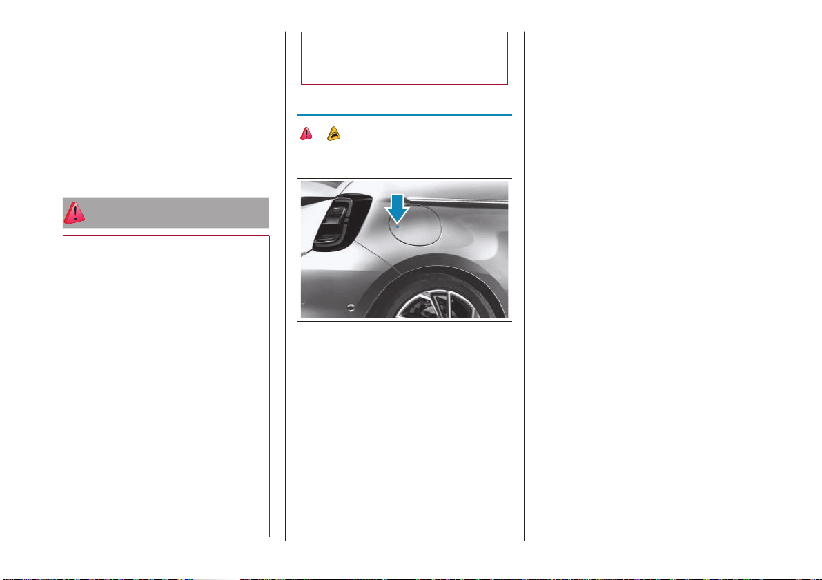
To access the charging port, open the
charging flap fig.24 by pressing on the
area indicated by the arrow.
CHARGING PORT LED
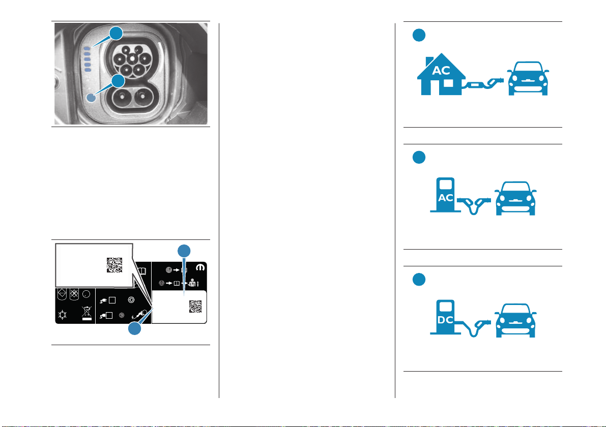
Next to the charging socket there are
some LEDs (A)fig.25 that indicate
the charging status by means of four
different colours and related flashing
types:
Blue: to indicate that the system is
waiting for a charging schedule
Flashing green: during the charging
process:
− one flashing green LED indicates
that charging is in progress
− all 5 green LEDs flashing: charging
process initialisation
Steady green: to indicate that the
charging process is complete
Blinking red: to indicate a fault in
the charging system or when there
is a fault in the charging procedure
(e.g. when the charging connector
is connected to the charging port
located on the car and the cable has
not been previously connected to the
power socket
WARNING If all the LEDs are off after
connecting the charging connector to the
charging port on the car, a problem may
have occurred during the process. In this
case it is advisable to press the key (B) in
fig.25, disconnect the charging connector
and reconnect it.
24
Page 26
A
B
25 F0S1367
WARNING Use only the charging cable
supplied with your car; refer to the label
on the control unit, which indicates the
"Country Group" (A) fig.26 and the
electrical current intensity (Ampere) (B) and
the table "Mode 2 Cable Variants" in the
"Power sources that can be used" chapter
of the Owner Handbook or a replacement
cable recommended by FCA.
COUNTRY GROUP 1
PLEASE READ MANUAL BEFORE USE
L
R
EU
F235
i
EU-GEN4.1-CHARGECORD
EU-GEN4.1-CHARGECORD
35344729
46345793
13A / 230VAC
LNSE SINGLE PHASE
004634579300F2350000119182
E346031
A
i
i
COUNTRY GROUP 1
MOPAR
F235
EU-GEN4.1-CHARGECORD
35344729
46345793
50 Hz
13A / 230VAC
RCD:b
LNSE SINGLE PHASE
n
AC
30mA
004634579300F2350000119182
n
DC
6mA
E346031
LR67 - ICCB
FUNCTIONAL
SAFETY
PE
U
IC-CPD
25
B
TYPES OF CHARGING
CABLES
Three different types of cables can be
used for charging:
Mode 2” charging cable (A)fig.27
(for versions/markets where provided):
allows charging from an earthed
domestic power socket. This type
of socket is used for charging with
alternating current. The "Mode 2"
charging cable complies with IEC
61851, IEC 62752 and SAE J1772
Mode 3”charging cable (B)fig.28 (for
versions/markets where provided):
allows charging from a public charging
station and a wallbox charging station
marked as AC stations (alternating
current). The charging speed can
be faster than when charging via a
domestic power socket
"Mode 4"- Fast Charge (C)fig.29
Charging cable: this allows charging
from public charging sockets marked
as DC (direct current). The charging
cable is connected to the charging
station
A
27 F0S1058
B
28 F0S1059
C
26 F0S1055
29 F0S1120
25
Page 27
ATTENTION
49) In order to reduce the risk of electric
shock or damage to the device, special
care should be taken when cleaning:
ALWAYS unplug the device from the
domestic power supply socket and car
ports.
WARNING
13) Do not charge if the outside
temperature is-30°C or lower, as
charging is likely to take longer and the
charging device may be damaged.
14) Do not leave the car or the charging
cable in areas where the outside
temperature is below-40°C as they
may be damaged. In cold temperatures,
the charging cable may become stiff.
Therefore, be careful not to apply
excessive force to the charging cable as
it may be damaged.
15) Do not use personal generators to
charge the high-voltage battery. This
may cause fluctuations in charging and
the voltage may be insufficient, resulting
in damage to the car system.
16) Charging the high-voltage battery
using incorrect or damaged sockets, or
charging cables and not following the
prescribed charging procedures may
cause short circuits, fire and potential
risk of damage to the electrical system
of the car.
17) Avoid leaving the battery for several
days with the charge indicator at or near
zero. The high-voltage battery may be
damaged.
18) You do not need to wait until the
battery level is low to recharge. The
performance of the battery is optimal
when it is charged regularly.
19) Charging the high-voltage battery
may take longer if the temperature of the
high-voltage battery is high or low.
20) During charging, especially with fast
charging, battery cooling components
may be activated. Therefore, it is normal
to hear noises during this operation.
ALTERNATING
CURRENT (AC)
CHARGING AT HOME
50) 51) 52) 53) 54) 55) 56) 57) 58)
5) 6) 7) 8) 9) 10) 11) 12)
CHARGING PROCEDURE
WARNING Always connect the cable
to the charging port of the domestic
mains first and only then to the car.
The car high-voltage battery is charged
by connecting the "Mode 2” (for versions/
markets where provided) charging cable
supplied with the car to an AC charging
port.
Refer to the "Power sources that can
be used- Mode2 cable” chapter in the
Owner Handbook for the specifications of
the "Mode 2” cable.
To charge, proceed as follows:
park the car safely (gearbox in position
"P"- Park)
turn the ignition device to the STOP
position
engage the electric parking brake
remove the charging kit located in the
luggage compartment or in the special
bag (for versions/markets, where
provided)
remove any dust that may have built
up on the charging connector and on
the charging port
26
Page 28

unroll the charging cable and connect
it to an AC charging
NOTE From the moment the plug is
connected to the domestic mains
charging port, the 3 LEDs on the control
unit of the cable will flash for approx.
6 seconds (control unit switching on
phase);
open the charging flap fig.24 by
pressing on the area indicated by the
arrow
remove the protective cover of the
charging port and attach it to the
device
grasp the charging connector by the
handle, remove the protective cover
(where provided) and insert it into the
charging port until you hear the click
indicating that it has been locked
if no scheduled charging has been set
(see the "Charging functions" chapter
in the "Starting and driving" section of
the Owner Handbook), charging starts
automatically
check by turning on the LEDs on the
cable control unit that there are no
faults in the charging system (for more
information, see "Charging status
control unit" in the "Power sources
that can be used- Mode2 cable"
chapter of the Owner Handbook).
If there are no anomalies, the green
LEDs located next to the charging
port will light up momentarily. In case
of anomalies, refer to the description
in "Charging system failure" in the
"Power sources that can be usedMode 2 cable" chapter of the Owner
NOTE The charge procedure is interrupted
when opening the bonnet: a dedicated
message will be shown on the instrument
panel display. The charge will be
reactivated when the bonnet is closed
correctly.
The time required for charging the
high-voltage battery depends on several
factors.
If the passenger compartment
preconditioning is activated, the battery
charging time will be extended. The
time required for heating/cooling the
car is mainly determined by the outside
temperature.
WARNING The maximum power
consumption of the charging port
depends on the type of contract signed
by the user, the type of cable used and
the charge level set in the Uconnect™
system menu.
WARNING Use only the charging cable
supplied with the car or a replacement
cable recommended by FCA.
WARNING The high-voltage battery
must be charged in accordance with the
maximum amperage rating allowed by
local and national recommendations for
charging electric vehicles.
END OF CHARGING
PROCEDURE
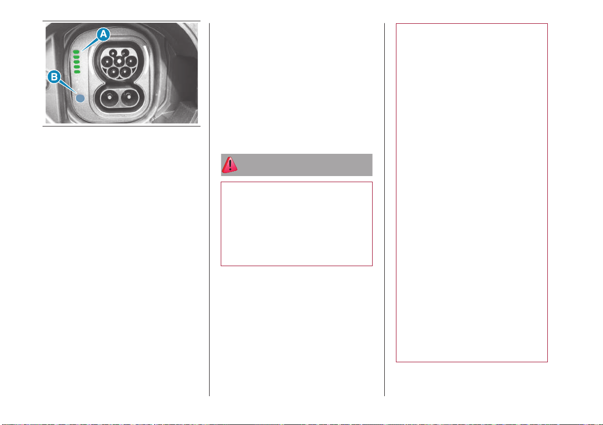
The charging procedure ends when all
the LEDs (A)fig.30, located next to the
charging port, will light up steady green
(during the charging phase, on the other
hand, the LEDs will light up flashing/fixed
green according to the state of charge of
the battery portion indicated by the LED.
The fixed green light indicates that the
battery portion is fully charged).
27
Page 29
30 F0S1220
DISCONNECTING
THE "MODE2"
CHARGING CABLE
During the charging procedure the cable is
automatically locked on the charging port
in the car.
To complete the charging, proceed as
follows:
unlock the doors of the car allowing
the charging cable to unlock
if charging is in progress, press button
(B)fig.30 on the charging port
disconnect the cable from the vehicle
charging port by grasping the handle
of the charging connector and
avoiding to pull the cable directly
disconnect the cable from the
charging port
reposition the protective cover of the
charging port
close the charging flap, making sure it
locks properly
roll up the charging cable correctly,
repositioning the protective cover
correctly on the charging connector
(where provided). When rolling up,
take care not to damage the cable.
Then store the cable together with the
charging kit
IMPORTANT Before disconnecting the
charging connector, make sure that the
doors are unlocked. If the door is locked,
the charging connector locking system
does not allow disconnection.
ATTENTION
50) Incorrect setting of the charge
current intensity can overload or
overheat the mains power supply of the
domestic power socket. Fire hazard.
Before charging from other domestic
sockets, adjust the charge current
intensity to the mains. If you do not know
the mains, set to the lowest level. Never
use extension cords for charging.
51) The charging current level ("Level
1"/ "Level 2"/ "Level 3", etc.) can only
be changed using the system display
Uconnect™ (for more information
see the "Uconnect™" chapter in the
"Multimedia" section of the Owner
Handbook). The default charge level
set is "Level 3". For countries in which
the 13A "Mode2" charge cable can be
used, if the domestic power socket IS
NOT CERTIFIED, it is recommended to
set "Level 4" charge to the maximum,
which corresponds to approx. 10A. For
the list of country-specific cable types
refer to what is indicated in the "Mode2
cable variant table" in the Owner
Handbook.
52) The set level applies indifferently to
both AC home charging (Mode 2) and
charging from an AC public charging
station (Mode 3). It is therefore always
advisable to check that the level is set as
desired for the actual charging type that
is about to be carried out.
53) Incorrect connection between
connector and charging terminals
constitutes a fire hazard!
54) During normal operation, the
domestic power socket can overheat.
In the case of extreme overheating, the
charge is interrupted and the warning
LED on the front of the cable control
unit will turn on. Refer to the table in the
"Charge system failure" paragraph in
the "Power sources that can be used"
chapter of the Owner Handbook.
28
Page 30
55) The "Mode 2" charge cable must
be connected to a dedicated circuit that
is not shared with other devices that
absorb electrical energy.
56) Do not insert fingers or objects in the
cable charging connector.
57) Keep the charging flap closed when
the charging port is not in use.
58) The high-voltage battery must only
be charged through preferred, grounded
domestic sockets or at a public charging
station using the supplied “Mode 3”
charging cable (for versions/markets
where provided).
DRIVING TIPS
During daily use, the consumption of
an electric vehicle may depend on the
following factors, which can have a
considerable impact:
Car maintenance
Tyre pressures
Unnecessary loads
Roof rack/ ski rack
Electrical devices
Using the air conditioning system
Aerodynamic control devices
FIX&GO
59) 60) 61) 62) 63) 64) 65) 66) 21) 22) 1)
The car may be equipped with a different
Fix&Go (Kit OPT1 or Kit OPT2) according
to the version.
Preliminary operations
Proceed as follows:
stop the car in a position that is not
dangerous for oncoming traffic where
you can change the wheel safely.
The car must be stopped in a lay-by,
car-park or parking or service area,
and the ground must be as level as
possible and sufficiently compact.
turn the ignition device to the OFF
position, apply the electric parking
brake and shift the gear to position P
or R
steer the wheels completely
in the event of a steep slope, place a
wedge or stone behind the wheels
before getting out of the car, put on
the reflective safety jacket (if required
by the regulations in force). In any
case, follow the road safety laws in
force in the country where you are
travelling.
make sure that any passengers get
out of the car and go to a safe place
where they will not obstruct traffic or
be exposed to the risk of injury. In the
event of a puncture, change the tyre
in accordance with the laws of the
country in which you are travelling
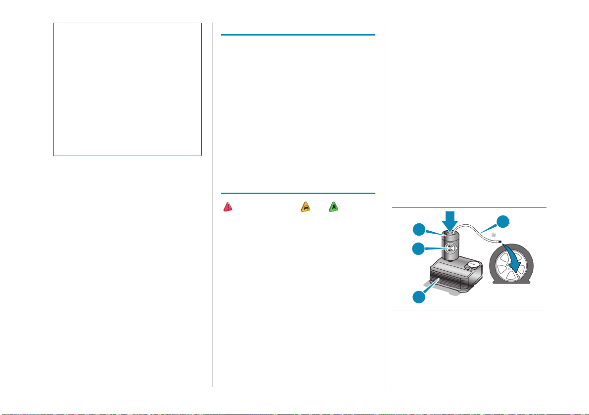
TYRE REPAIR (OPT1 Kit)
A
D
C
B
31 F0S1246
29
Page 31
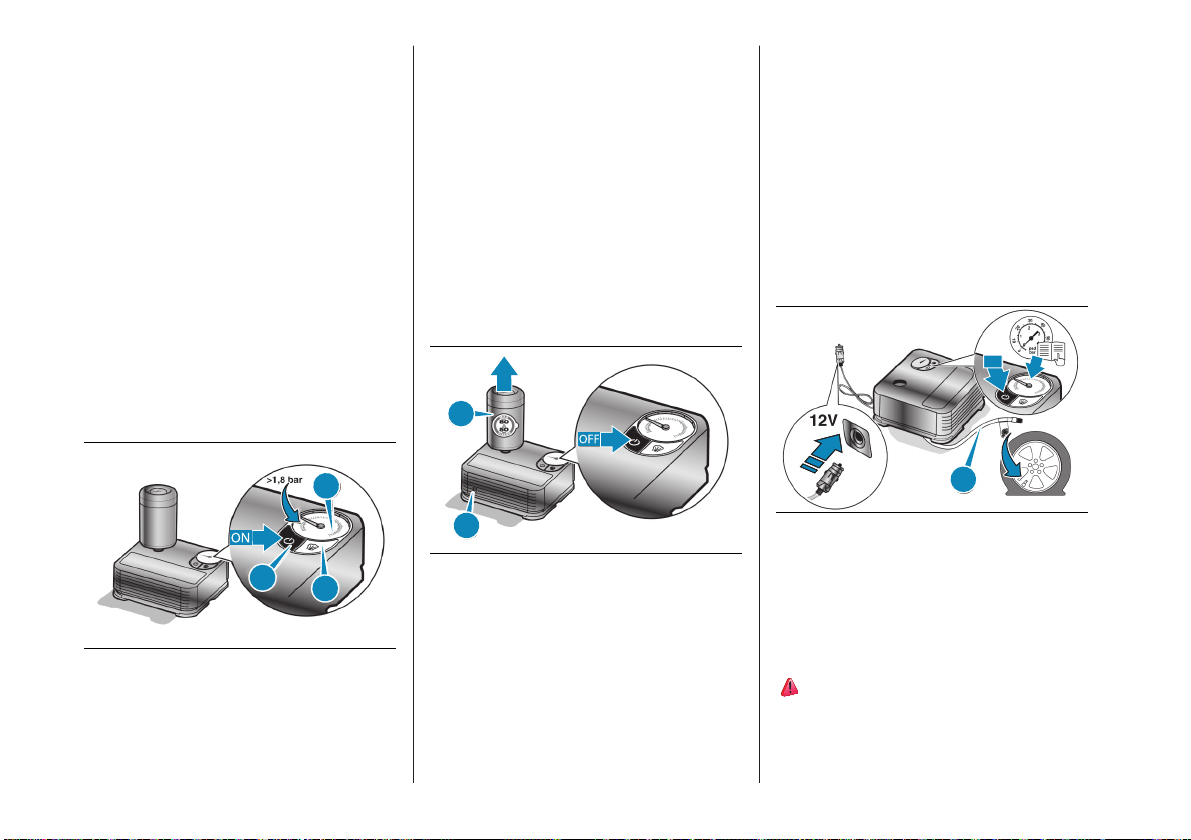
Proceed as follows:
insert the (cartridge A)fig.31
containing the sealant in the proper
compartment of the compressor (B),
pressing it down hard. Remove the
adhesive speed label (C) and apply it
in a visible position
wear the gloves
remove the cap from the tyre
valve and connect and screw the
transparent tube of the sealing fluid
(D) fig.31 onto the valve. If a 250ml
cartridge is present the housing of the
transparent tube is provided with a
removable ring to facilitate extraction
make sure that the ON– OFF button
(E)fig.32 in the off position (button not
pressed)
operate the compressor by pressing
the ON/OFF button (E) fig.32. When
the pressure gauge (G) displays
the prescribed pressure (see in this
manual the “Wheels” chapter or
the “Wheels” chapter in the online
Owner Handbook in the “Technical
Specifications” section), turn off the
compressor by pressing the ON–OFF
button again)
disconnect the cartridge (A)fig.33
from the compressor by pressing the
release button (H)fig.33 and lifting the
cartridge upwards
A
Stop safely, engage the electric parking
brake and restore the pressure to the
prescribed value using the black inflation
pipe (I) fig.34. If also in this case, the
pressure is lower than 1.8 bar (26 psi) 15
minutes after turning on, do not resume
driving but contact a Dealership.
After driving for about 8km/ 5miles,
place the car in a safe and suitable area,
engaging the electrical parking brake. Take
the compressor and restore the pressure
using the black inflation hose (I)fig.34.
ON
G
H
E
32 F0S1262
L
insert the electrical connector in the
12 V current socket of the car and start
the engine
33 F0S1263
If the pressure gauge (G) fig.32 indicates
a pressure lower than 1.8 bar (26 psi) 15
minutes after starting the compressor,
switch off the compressor, disconnect the
sealing fluid tube (D) fig.31 from the tyre
valve and remove the cartridge (A) from
the compressor.
Move the car by approximately 10 metres
to allow the distribution of the sealant.
30
I
34 F0S1264
If the pressure shown is higher than 1.8
(26 psi), restore the pressure and carefully
drive to a Dealership in the shortest
possible time. Otherwise, if the pressure
is less than 1.8 (26 psi, do not resume
driving, but contact a Dealership.
67) 68)
Page 32
Inflation procedure
Proceed as follows:
stop the car safely, as described
above, and engage the electric
parking brake
extract the black inflation tube
(I)fig.34 and screw it firmly onto the
tyre valve
Press the air (L) fig.32 of release button to
adjust any tyre overpressure.
TYRE REPAIR (OPT2 Kit)
69) 70) 71)
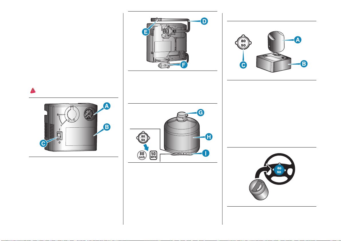
36 F0S0823
(D) Air pipe
(E) Deflation button
(F) Power supply cable/ 12 V plug
35 F0S0822
(A) Pressure gauge
(B) Instruction label
(C) ON-OFF switch
37 F0S0824
(G) Cap for the sealant bottle
(H) Sealant bottle and expiry date
(I) Speed label
Description
38 F0S0825
The tyre quick repair kit fig.38 is located
in the boot or in the tool bag and is
comprised of the compressor (B) fig.38
and a cartridge (a) containing the sealant
and an adhesive label (C) with the writing
“Max 80Km/h”, to be applied in a visible
position (e.g. dashboard) after repairing
the tyre.
Repair procedure
39 F0S0826
31
Page 33
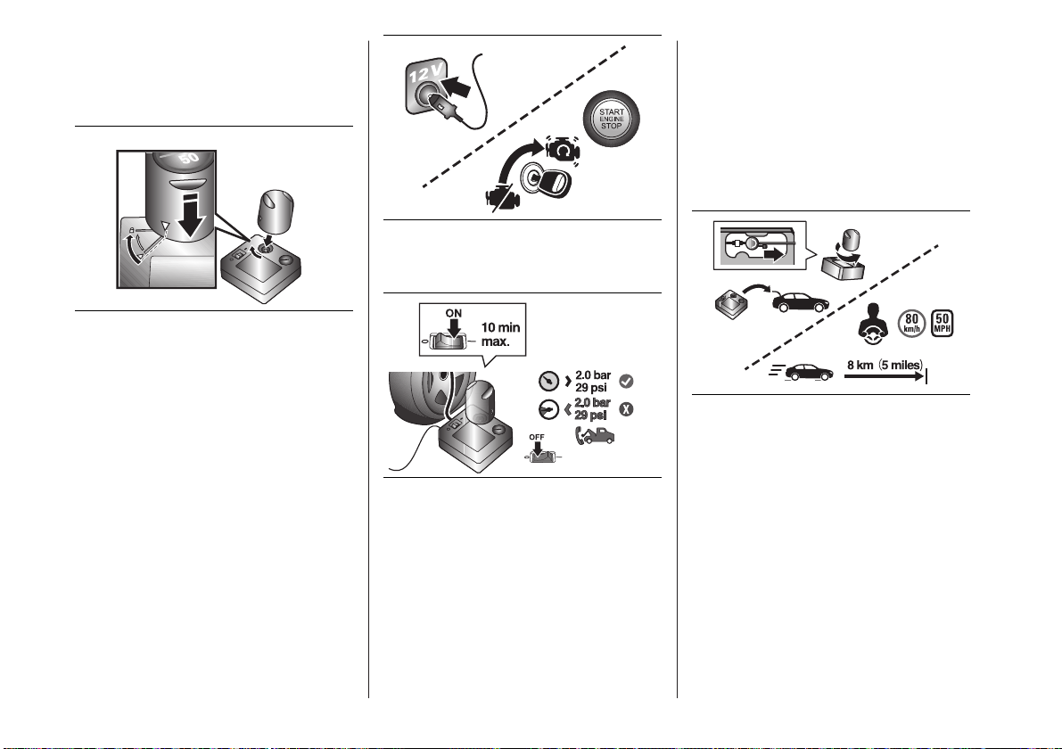
Proceed as follows:
Take the kit, detach the speed limit
sticker (I) fig.37 and apply it in a
clearly visible position fig.39
40 5520954D
open the cap on the compressor,
engage the cartridge and turn a
quarter turn clockwise, fig.40
remove the cap from the tyre valve
and screw the black compressor tube
onto the valve
make sure that the ON/OFF button is
in the off position (button in position 0)
41 5520955D
insert the electrical connector fig.41
into the 12V socket on the car
42 5520956D
activate the compressor setting the
ON-OFF button, fig.42, to the on
position (button in position I)
when the pressure gauge displays the
prescribed pressure indicated in this
handbook in the “Wheels” chapter or
in the “Wheels” chapter in the online
Owner Handbook in the “Technical
Specifications” section or on the
specific label, turn off the compressor
by moving the button to the OFF
position (O)
43 5520957D
If the pressure gauge fig.43 indicates
a pressure lower than 2 bar/ 29 psi 10
minutes after starting the compressor,
switch off the compressor, disconnect the
black tube of the compressor from the
tyre valve and undo the cartridge from the
compressor turning it by one quarter of a
turn anticlockwise and lift it. Move the car
by approximately 10 metres to allow the
distribution of the sealant.
32
Page 34
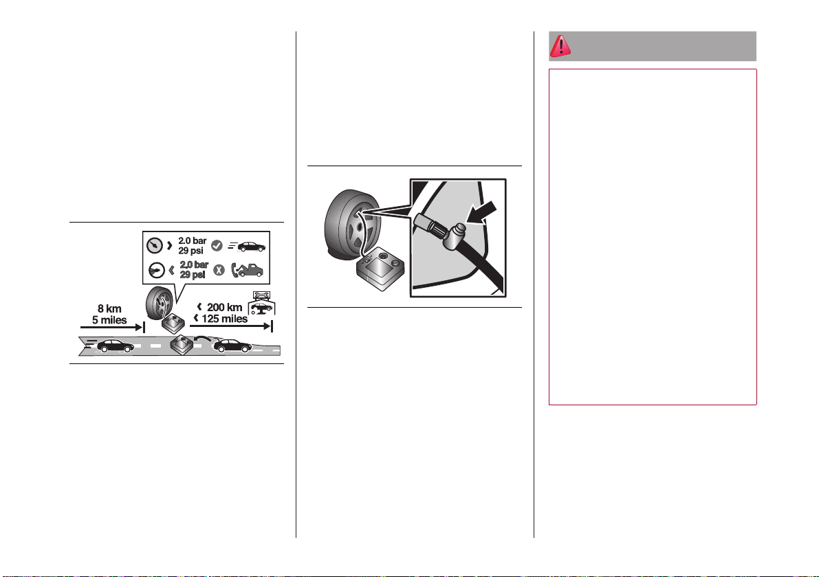
Stop the engine, switch on the hazard
lights; stop the vehicle safely, apply the
parking brake; engage 1st gear if uphill or
reverse gear if downhill; wheels all steered;
on a steep gradient, place a wedge or
stone behind the wheels and restore
pressure using the black compressor tube
fig.42 until the prescribed pressure is
reached.
If also in this case the pressure is lower
than 2 bar/ 29 psi 10 minutes after
turning on, do not resume driving and
contact a Dealership.
44 5520958D
After driving approximately 8 km/ 5 miles,
place the vehicle in a safe and easy area,
stop the engine, switch on the hazard
lights, apply the parking brake; engage
1st gear if uphill or reverse gear if downhill
with wheels all steered. In the event of
a steep slope, place a wedge or stone
behind the wheels.
Take the compressor and restore the
pressure using the black inflation tube. If
the pressure shown is higher than 2 bar/
29 psi, restore the pressure and carefully
drive to a Dealership in the shortest
possible time. Otherwise, if the pressure
is less than 2 bar/ 29 psi, do not resume
driving, but contact a Dealership.
Pressure relief valve
45 5520959D
If the tyre pressure is higher than
expected, it is possible, after switching off
the compressor, to lower it by means of
the fig.45 button located next to the black
tube connection.
ATTENTION
59) IMPORTANT: Do not exceed
80km/h. Avoid sudden acceleration or
braking. The Kit provides a temporary
repair, therefore the tyre must be
examined and repaired by a specialist
as soon as possible. Before using the
Kit, ensure that the tyre is not damaged
excessively and that the rim is in good
condition, otherwise do not use it and
call roadside assistance. Do not remove
foreign bodies from the tyre.
60) Punctures on the sides of the tyre
may not be repaired. Do not use the Kit
if the tyre was damaged as a result of
being used with the wheel underinflated.
61) Wear the protective gloves provided
with the Kit.
62) Apply the adhesive label where it can
be easily seen by the driver as a reminder
that the tyre has been treated with the
Kit. Drive carefully, particularly on bends.
63) Repairs are not possible in the case
of damage to the wheel rim (bad groove
distortion causing air loss). Do not
remove the foreign body (screws or nails)
from the tyre.
33
Page 35
64) As required by current regulations,
the information on chemical substances
for the protection of human health and
the environment and on the safe use of
the sealing fluid are on the packaging
label. Compliance with the indications
on the label is an essential condition to
ensure the safety and the effectiveness
of the product. Remember to carefully
read the label before use; the user of the
product is responsible for any damages
caused by improper use. The sealing
fluid has an expiry date. Replace the
bottle if the sealant has expired.
65) The Kit is not suitable for definitive
repairs, so the repaired tyres may only
be used temporarily. The Kit provides a
temporary repair, therefore the tyre must
be examined and repaired by a specialist
as soon as possible.
66) Alert other drivers that the car is
stationary in compliance with local
regulations: hazard warning lights,
warning triangle, etc. Any passengers
on board should leave the car, especially
if it is heavily laden. Passengers should
stay away from on-coming traffic while
the wheel is being changed. On hills or
uneven roads, use chocks or appropriate
objects to block the wheels of the
vehicle.
67) Never operate the compressor for
longer than 20 consecutive minutes. Risk
of overheating.
68) If the pressure falls below 1.8 bar,
do not drive any further: the Kit cannot
guarantee proper seal because the tyre is
too damaged. Contact a Dealership.
69) Carefully read the cartridge label
before use and avoid improper use. The
kit should be used by adults and cannot
be used by children.
70) Do not let the compressor turned on
for longer than 10 consecutive minutesoverheating hazard.
71) Use the kit only in case of a
punctured tyre.
WARNING
21) The sealant fluid is effective with
external temperatures from-40°C to
+50°C. The sealant fluid has an expiry
date and must be replaced periodically.
It is possible to repair tyres with tread
damage up to a maximum diameter of
6mm. Show the cartridge and the label
to the personnel who will handle the tyre
treated with the Kit.
22) The surface of the tube may be hot.
WARNING
1) Do not dispose of the sealing fluid can
in the environment. Have them disposed
of in compliance with national and local
regulations.
REPLACING
THE BULBS
72) 73) 74) 23) 24)
LED FRONT AND SIDE
DIRECTION INDICATORS
Contact a Dealership for replacement.
LED MAIN BEAM/DIPPED
BEAM HEADLIGHTS
Contact a Dealership for replacement.
LED SIDE LIGHTS/DAYTIME
RUNNING LIGHTS (DRL)
Contact a Dealership for replacement.
REAR LIGHT CLUSTERS
The position, stop, third stop, number
plate and direction indicators are of
the LED type. Contact a Dealership for
replacement.
34
Page 36
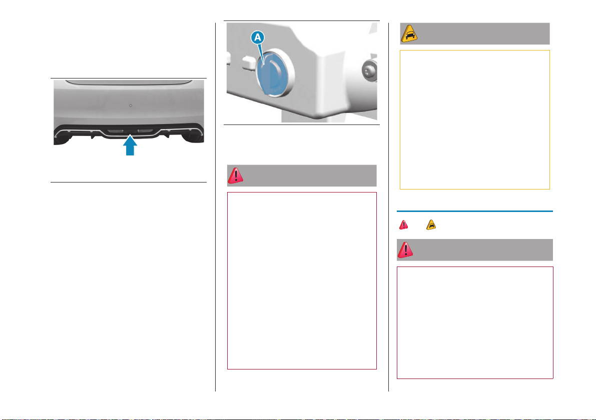
REVERSING LIGHT/
REAR FOG LIGHT
To replace the reversing and rear fog light,
access the bulb holder through the lower
part of the rear bumper fig.46.
46 AB0A0578
turn the bulb holder (A)fig.47
anticlockwise and pull it out
undo the outer lamp holders to
replace the reversing lights
undo the central bulb holder to replace
the rear fog light
release the bulb and replace it
47 F0S1165
reinsert the bulb/bulb holder unit (A) by
turning it clockwise
ATTENTION
72) Modifications or repairs to the
electrical system that are not carried
out properly or do not take the system
technical specifications into account can
cause malfunctions leading to the risk
of fire.
73) Halogen bulbs contain pressurised
gas, in the case of breakage they may
burst causing glass fragments to be
projected outwards.
74) Only replace the light bulbs when the
engine is off and in a position that does
not interfere with traffic and lets you
safely replace them (see the description
in the “When parked" chapter in the
"Starting and driving" section of the
Owner Handbook). Also ensure that
the engine is cold, to prevent the risk of
burns.
WARNING
23) Halogen bulbs must be handled
holding the metallic part only. Touching
the transparent part of the bulb with
your fingers may reduce the intensity of
the emitted light and even compromise
duration of the bulb. In the event of
accidental contact, wipe the bulb with a
cloth moistened with alcohol and let the
bulb dry.
24) Where possible, it is advisable to
have bulbs changed at a Dealership. The
correct operation and direction of the
external lights are absolutely essential for
the safety of the car and of compliance
with the law.
FUSES
75) 76) 25)
ATTENTION
75) Replacement of a fuse. All work
may be performed only by a Dealership
or a qualified repair workshop. The
replacement of a fuse by a third party may
cause a serious car fault.
76) Installation of electrical
accessories. The electrical circuit in the
car is designed to function with standard
or optional equipment, so contact a
Dealership or a qualified repair workshop
before installing other electrical equipment
or accessories in the car.
35
Page 37
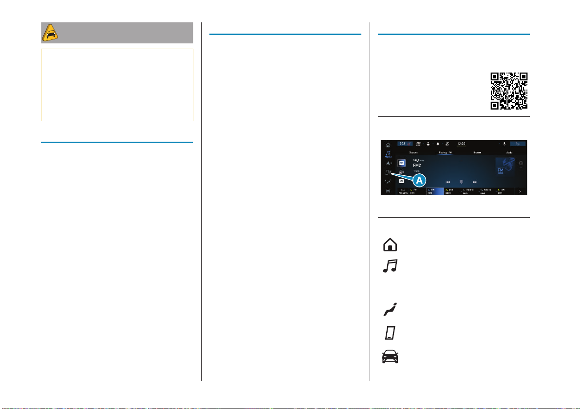
WARNING
25) FCA shall not be held liable for
expenses arising from car repairs or faults
due to installation of accessories not
provided or recommended by Abarth and
not installed according to specifications,
in particular when the combined
consumption of all additional equipment
connected exceeds 10 mA.
REFILLING
EDM (Electronic Drive Module)
0.67 litres (PETRONAS IONA INTEGRA
PLUS FCA)
Cooling system
6.5 litres (Mixture of demineralized water
and 50% PARAFLUUP) (*)
Hydraulic brake circuit
0.8 kg (TUTELA TOP EVO)
Windscreen and rear window
washer fluid reservoir
1.5 litres (Mixture of water and
PETRONAS DURANCE SC35)
(*) When the vehicle is used in particularly
harsh climate conditions, we recommend
using a 60% mixture of PARAFLUUP and
40% demineralised water.
WHEELS
COLD TYRE INFLATION
PRESSURE (BAR)
205/45 R17 88H XL, 205/40 R18 86HXL
Medium load:
front: 2.4 bar
rear: 2.3 bar
Full load:
front: 2.4 bar
rear: 2.5 bar
When the tyres are warm, the inflation
pressure should be + 0.3 bar in relation
to the recommended figure. With snow
tyres, add +0.2 bar to the pressure value
prescribed for other standard tyres.
However, recheck the correct value when
the tyre is cold.
UCONNECT™
GRAPHIC BUTTONS
ON DISPLAY
(A) fig.48
48 AB0A0596
Home: Show the main screen
Media: Access Media mode to
select available sources, folder
tracks and interaction with audio
settings
Comfort: Climate control
system settings
Phone: Access to the Phone
mode
Vehicle: Access to additional
car settings and functions
36
Page 38
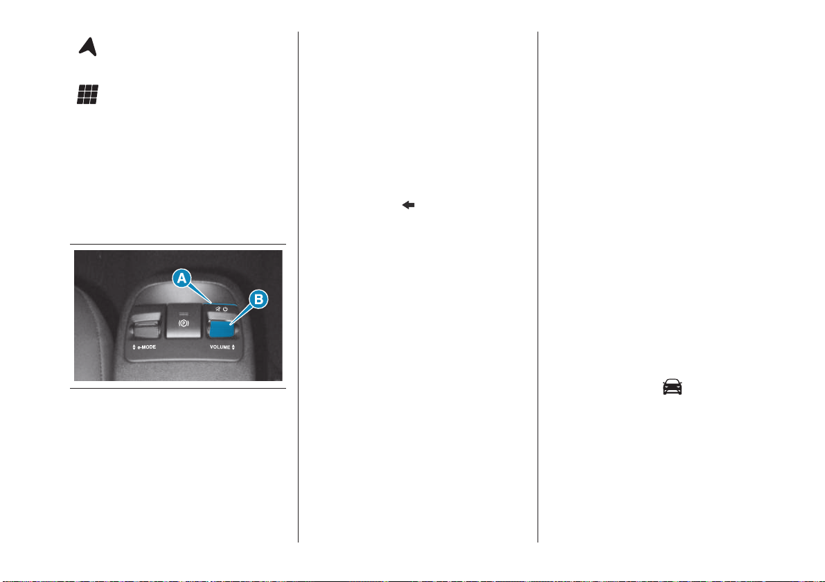
Navigator (10.25" Uconnect™
version only): Start Navigation
system
App: Access the list of available
Apps
CONTROLS ON THE
STEERING WHEEL
E BEHIND THE
STEERING WHEEL
See the description in the "Car interior"
fig.2 chapter.
CONTROLS ON
CENTRAL CONSOLE
49 AB0A0503
(A) Uconnect™ on/off (long press)-
Mute function enable/disable (short
press)
(B) Rotary control volume control
TOUCHSCREEN FUNCTION
The system uses the touchscreen
function; to interact with the different
functions, press the graphic buttons
displayed.
To confirm the selection, press the
button "OK" or tick the required selection.
Confirmation of some functions or settings
is accompanied by a dedicated chime.
To go back to the previous screen,
press the (Delete) button or, depending on
the active screen,
To go back to the home screen or
home position press the HOME graphic
button. The "touchscreen" function can
be used to access and view the available
lists of music tracks, phone numbers,
settings, etc. Move your finger on the
screen to scroll lists and selections. Hold
your finger down and move up to display
the list items at the bottom; move down to
display the list items at the top.
Hold your finger down on the screen and
move your finger rightwards, to see the
lists to the left; move your finger leftwards,
to see the lists to the right of the screen.
The same operation can be performed to
move between pages. Press your finger
on the chosen field or button to select the
field or perform the function associated
with the button.
.
USB SOURCE
There are two USB ports. The first one is
located on the dashboard for data transfer
to the Uconnect™ system and for
charging external devices; the second one
is inside the central console for charging
external devices only.
APPLE CARPLAY AND
ANDROID AUTO
To activate Apple CarPlay and Android
Auto connect a compatible smartphone
to the USB port of the car or in Wireless
mode. The contents of the phone will be
automatically shown on the Uconnect™
system display. After the setup procedure,
the application will run automatically
on the Uconnect™ system when your
smartphone is connected to the USB port
in the car.
WARNING The “double telephone” feature
is not available while using the telephone
in CarPlay or Android Auto mode.
VEHICLE MODE
Pressing the "Vehicle" fig.48
graphic button to access the pages:
"Electric Vehicle", "Controls" and "System
Settings".
Controls
The "checks" label contains, for
example: "screen settings OFF", "internal
electrochromic mirror" (where provided),
"rear camera" (where provided).
37
Page 39

Electric vehicle
The following submenus are available to
the user on the "Electric vehicle" page:
Power flows, History, Programming and
Charge Status.
Power Flow shows in a chart the power
flow used by the battery, the electric motor
and the climate control system.
History shows the power flows used up
to 15 minutes before or in the previous 7
days.
Programming can be used to program
the charging of the high voltage battery
or climate control system when the car is
parked.
The page shows a summary of the
programmed charging and climate
control system operations with respective
times and days of activation. Select
"New programming" to define a new
programmed charging or climate control
system operation.
When programming a battery charging
operation, select "Operating frequency" to
set the day and time for the start and end
of charging.
When programming the climate control
system, a pop-up with the ignition device
in the OFF position will ask the user
whether to recharge the high-voltage
battery or not despite the programmed
function. Set the desired day and time to
start the climate control system from this
page.
The Charging status shows the current
battery level and gives an estimate of the
maximum and minimum charging time
(depending on the power supplied by the
charging station). For home charging,
you can also set five different power
consumption levels according to your
needs. To adjust the power level, select
one of the five values from "1" (lowest
current) to "5" (maximum current) on this
page. The estimated time displayed on the
screen will be updated accordingly.
WIDGETS
On the main page, you can view summary
pages of Uconnect™system functions
(called "Widgets") from a list of available
Widgets. To add a Widget, press the
button on the display and select the
desired Widget from the list.
Some Widgets can also be customised
by pressing the button
This will open the customisation screen.
The number of Widgets which can be
installed per page depends on their
size. You can add multiple pages (up to
a maximum of five in total) by pressing
the "+" button on the display. To switch
between pages, simply touch the page
briefly and swipe your finger rightwards or
leftwards.
Pages can be deleted using the "Delete
page" function or reordered using the
"Reorder pages" function.
next to the title.
NOTE Customisation is only active when
the car is stationary. If an attempt is made
to customise with the car in motion or to
resume driving without having completed
the procedure, a warning message will
appear on the display and the operation
will be ended.
38
Page 40
CONNECTED
SERVICES
For further information:
OFFICIAL TYPE
APPROVALS
Radio devices
The radio equipment provided with the car
complies with the 2014/53/EU directive,
UA.RED.TR, the French SAR Decree
Law dated 15/11/2019 and the UKCA
(UK Conformity Assessed) Certification
dated 01/01/2023 in force in the United
Kingdom.
Radio frequency devices
All radio frequency devices comply with
the regulations in force in the countries in
which they are sold.
For further information go to
www.mopar.eu/owner or
http://aftersales.fiat.com/elum.
39
Page 41

40
FCA Italy S.p.A.– Technical Service Operation
Via Adige 7, 10040 Rivalta di Torino (TO)- Italy
Print no. 603.85.831- 06/2023- 2 Edition
Page 42

ENGLISH
 Loading...