

Aanalog and digital systems PH30.2 User Manual

analog and digital systems
PH30.2
owner's manual
front_cover.qxd 10/26/56 5:13 AM Page 2

table of contents
introduction 1
about this manual 2
features of your PowerPlate™ 2
warning and tips 3
mounting locations 3
system planning 4
system configurations 5-9
amplifier and crossover controls 10-11
installation 12
controls and connections 12-13
signal sources 14
internal signal routing 15
multi-cross™ crossover and configurations 16
constant bass control 17
AC502 operation 17
tuning 17-18
troubleshooting 19-20
specifications 21
warranty information 22
introduction
Although it may be hard to remember, back in the 1970’s, car audio as we now know it didn’t really exist.
Sure, music lovers could buy a cassette or 8-track tape deck and some 6" x 9" three-way speakers.
Advanced stereo buffs might even add a "power-booster" to increase output too as much as 12 watts
RMS! But none of this really delivered the power to cut through road noise with sound quality that
compared with the best home audio. Not until 1979 that is, when a/d/s/ introduced the revolutionary
PowerPlate™ P100 amplifier and 300i 2-way plate loudspeakers. Aesthetically, the P100 introduced the
low profile design which has been an a/d/s/ trademark to this day. Technologically, the P100 combined a
high efficiency switching power supply with a state-of-the-art, discrete high-current stereo power
amplifier. For the first time, a car audio system existed with the musical integrity and dynamic range that
made you want to take long drives to nowhere, just to listen to the music. High quality car audio was
born, and the original a/d/s/ PowerPlate™ P100 made it happen.
The latest improvements to the PowerPlate™ line-up include increased heatsink area to facilitate higher
power output, Constant Bass circuit for subwoofer signal that can be mixed into all channels, and fully
balanced high-level inputs compatible with any source. The amplifier you have purchased is an
enhancement of the respected P-series multichannel amplifiers. In this version, we have improved upon
the already acclaimed sound quality by addressing internal details, and upgrading selected components
to incorporate the latest technology which was not available when the P-series was originally designed.
Selected low-noise, high-speed Burr-Brown® op amps are used in critical circuits. Class-A biasing is used
throughout the voltage-gain and active crossover stages. Numerous modifications and "tweaks" were
also performed which improve the power supply dynamics and reduce noise. These changes improve
transparency and dynamic linearity, resulting in a smoother and more detailed top-end, tighter bass, more
explosive dynamic contrasts, and virtually holographic imaging. Left intact are the P-series unequalled
flexibility, high efficiency and superb reliability. These, along with multichannel design, are fundamental in
the a/d/s/ approach to systems engineering, which makes achieving true high fidelity reproduction simple
and predictable in any installation.
1

about this manual
To get the most from your a/d/s/ PowerPlate™, we recommend that you have the installation performed
by your qualified authorized a/d/s/ dealer. If this unit is installed by your dealer, we will extend the warranty
to two years instead of the standard one-year. However, if you feel that you have the necessary skills and
prefer to perform the installation yourself, this manual will guide you through the process of installation
and set-up. Please read through it completely before beginning the installation so that you may familiarize
yourself with the total procedure before you begin. If there is anything that you do not fully understand,
please consult with your a/d/s/ dealer before attempting the installation.
keep listening, but be safe!
Sustained listening to loud music over 100dB has been shown to cause permanent hearing damage.
Systems using a/d/s/ components are capable of achieving volume levels, which substantially exceed this
level. When operating your system for sustained periods at high volume, be sure to use hearing protection
to prevent long-term exposure. We want you to be able to enjoy the music for many more years.
features of your PowerPlate™
Transient Perfect™ MOSFET Power Supply - The heart of the P-series, this supply frees the
PowerPlate™ from the constraints of common pwm (pulse width modulated) supplies. The advantages
are: extremely fast overload recovery time, low output impedance for superior damping, and stability
during voltage fluctuations for reliable performance in the harsh automotive environment.
Remote Subwoofer or Constant Bass Level Control Capability - Can be used with accessory control
AC502 to provide a dashboard mounted rear channel subwoofer or Constant Bass level control.
Digital Crossover Frequency Display - The crossover frequency for each channel pair is displayed on
the top of the amplifier for quicker, more precise system tuning.
Detachable Plug in Connectors - High current speaker and power connectors simplifies installation.
Multi-cross™ Variable Built-in Crossovers - High-pass, Low-pass and Bandpass functions are built-in,
virtually eliminating the need for external crossover networks in even the most elaborate systems.
Constant Bass circuit - Signal from all input channels is summed, low-pass filtered and then made
available to all channels.
PowerPlate™ Design - a/d/s/ original low profile, high efficiency heatsink design keeps size minimum
and allows mounting where space is limited.
Wide Input Sensitivity Range - Allows connection to virtually any source unit from factory OEM radios
through low output preamps.
Simultaneous Stereo and Mono - Each channel pair may be used Stereo, Mono, Bridged or both Stereo
and Mono simultaneously. This allows an additional Mono speaker to be used with a stereo pair for
center-channel or subwoofer applications from each channel pair.
Same Side Adjustments - The P-series PowerPlate™ makes system adjustment easy by organizing all
signal-processing controls on one side of the amplifier. This layout allows convenient system adjustment
and facilitates a variety of installation possibilities when access to the controls is desired.
2
warnings and tips
Always disconnect the battery ground wire before doing any work on your vehicle. Reconnect the cable
only after the installation is complete and the wiring has been checked to make sure that there are no
problems. If your radio features a code type security system, be sure you know the code before
disconnecting the battery!
Your a/d/s/ PowerPlate™ should be installed in 12V negative ground vehicles only. Connection to other
types of electrical systems may cause damage to the vehicle or the amplifier. Wear Eye and Ear protection
when using power tools.
Before cutting or drilling carefully inspect the area to make sure there are no electrical wiring, fuel lines
or brake lines that could be damaged. Sometimes these components may be hidden between doublewalled panels, so be very careful.
Do not bypass or modify the fuses, or replace with one of a higher rating. The fuse should not fail under
normal operation. Repeated blowing indicates a problem with the amplifier or improper installation. An
additional power supply line fuse (not supplied) must be installed on the 12V supply line and located as
close as possible to the battery in order to protect the wire in the event of a short circuit.
Make sure the system is turned off when making or breaking any connections. Do not use your PowerPlate™
with speakers which have either terminal connected to the speaker frame or to the vehicle chassis.
mounting locations
Due to its low profile, there are many possible choices of mounting locations. Always mount the
PowerPlate™ in a place that protects it from the elements. In addition, mount the PowerPlate™ on a
stable, flat mounting surface. Whenever possible, pre-drill the mounting holes. Remember to check
behind the panel for hidden dangers in the form of hoses, fuel or brake lines or electrical wiring. Use a
marking pen or awl to mark the hole locations and pre-drill using a 1/8" bit.
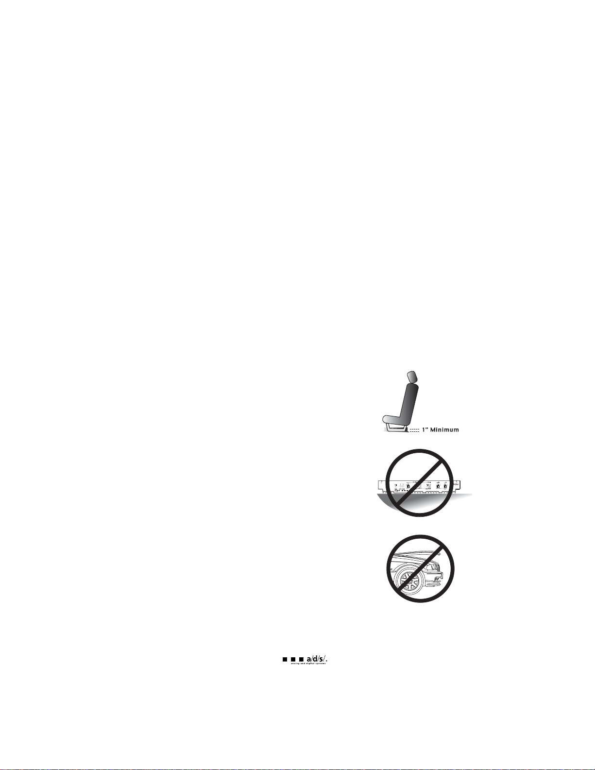
Passenger compartment mounting
All PowerPlates™ have been designed with a low profile to make under
seat mounting possible. Regardless of where you choose to mount your
PowerPlate™ be sure to keep a minimum of 1" of clearance around the
amplifier for adequate airflow to prevent overheating.
Trunk compartment mounting
The most common mounting location is in the trunk or cargo
compartment. For optimum cooling, mount the PowerPlate™ chassis
vertically with the fins running vertically, or mount the PowerPlate™
horizontally with the fins pointing upward. Avoid horizontal mounting
locations with the fins pointing downward.
Also, locate the PowerPlate™ where it, and connections to it, will not be
damaged by cargo or tools, which may shift during vehicle operation.
Engine compartment mounting
Don’t even think about it! The PowerPlate™ was not designed to endure
the harsh chemical and heat environment of the engine compartment.
Failure to obey this warning will void your warranty.
3
system planning
Proper system planning is the best way to maximize your PowerPlate’s™ performance. By planning your
installation carefully you can avoid situations where the performance or the reliability of your system is
compromised. Your authorized a/d/s/ dealer has been trained to maximize your system’s sonic potential.
Your a/d/s/ dealer is a valuable resource in helping you with your system design and installation.
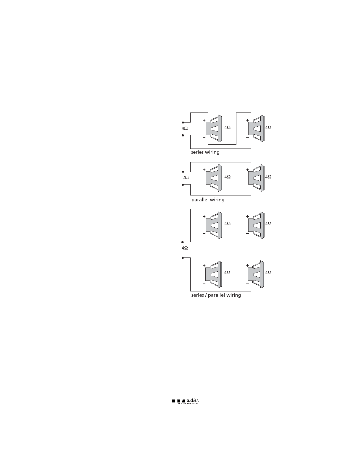
speaker requirements
Each channel of your PowerPlate™ can
easily drive 2 speaker loads when used in
the stereo mode. When a channel-pair is
bridged, the recommended minimum load
impedance is 4 for subwoofer use, and 4
for full range operation. Although operation
with lower impedances is not likely to cause
immediate damage to the internal circuitry,
the unit will most likely overheat, causing the
thermal protection circuitry to shut down the
amplifier. When the chassis cools down,
normal operation will resume. Continuing to
operate the amplifier under these conditions
is not recommended and will reduce its life
expectancy.
Most speakers designed for car audio
operation are 4 impedance. Connecting
two such speakers in parallel will result in a
2 impedance load as seen by the amplifier.
Some a/d/s/ subwoofer models feature a
dual 4 voice coil design. Connecting these
voice coils in parallel will result in a 2
nominal impedance, which is not
recommended for use with bridged channels
of your PowerPlate™.
4
system configurations
All a/d/s/ PowerPlates™ provide extensive features, which make a variety of system configurations
possible. It is not feasible to cover all of the possibilities within the few pages of this manual. There are a
few system configurations, however, which are extremely popular when used alone or as a "building
block" of a larger more elaborate system. Please review systems 1 through 6 described below for
suggestions on how to configure the most popular combinations. Larger systems may be built from a
combination of the simpler building blocks as shown in systems 7.
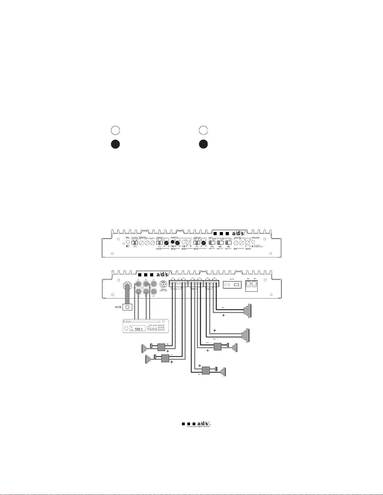
button is disengaged control is non-operational
button is engaged control is operational
System 1 - PH30.2 used in 6-channel mode. Channels 1 and 2 are used for front high-pass speakers,
channels 3 and 4 are used for rear high-pass speakers and channels 5 and 6 are used to drive a stereo
pair of subwoofers. Although shown as a 4-channel input, the source unit can be either 2 or 4 channel
depending on the setting of the 2/4 channel switch.
Note: Optional AC502 can be used in this system to adjust the level of the subwoofers.
5
70A
subwoofer
subwoofer
rear left
satellite
rear right
satellite
front left
satellite
front right
satellite
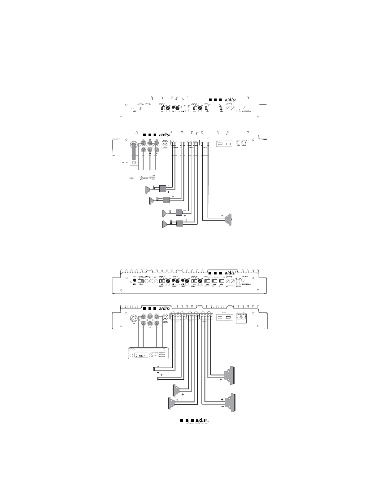
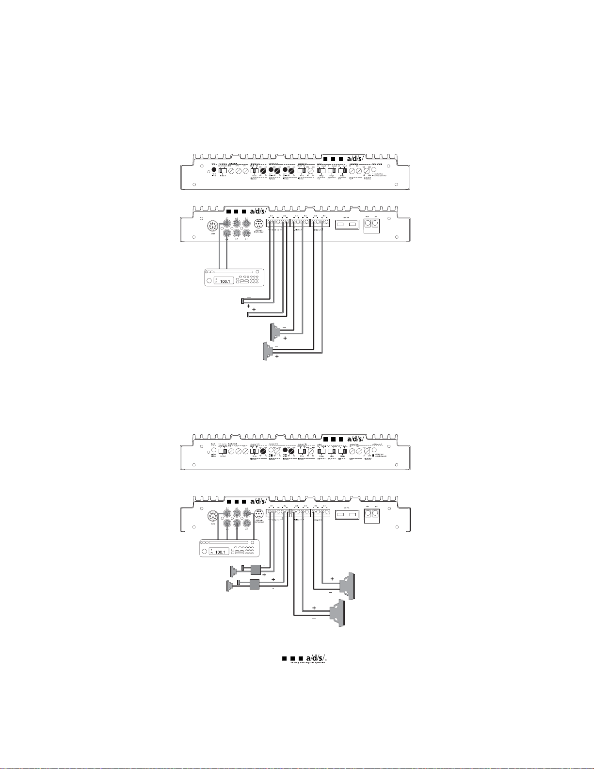
System 2 - PH30.2 used in 5-channel mode with the AC502 providing level control for bridged channels
5 and 6. 1 and 2 are high-passed for front speaker and channels 3 and 4 are high-passed for rear
speakers. Although shown as a 4-channel input, the source unit can be either 2 or 4-channel depending
on the setting of the 2/4 channel switch.
System 3 - PH30.2 used in 6-channel mode with source unit providing direct level control for channels 5
and 6 through the fade control. Channels 1 and 2 are configured high-pass for tweeters, channels 3 and
4 are configured bandpass for midrange and channels 5 and 6 are configured low-pass for subwoofers.
6
front left
satellite
front right
satellite
rear left
satellite
rear right
satellite
subwoofer
70A
70A
left tweeter
right tweeter
left midrange
right midrange
subwoofer
subwoofer
System 4 - PH30.2 used in 4-channel mode with high-pass tweeters and bandpass midrange. Channels
1and 2 are configured high-pass for the main tweeters and channels 3 and 4, and 5 and 6 are configured
bandpass for main midrange. Channels 4 and 6 are controlled by the 3/4 level control and crossover
section. The amplifier is configured for a 2-channel input.
System 5 - PH30.2 used in 4-channel mode with high-pass main speakers and low-pass
subwoofers.Channels 1 and 2 are configured high-pass for front speakers and channels 3/4, and 5/6 are
configured low-pass for bridged output subwoofers. The amplifier is configured for a 4-channel input.
Front/rear fade adjusts subwoofer level.
7
left tweeter
right tweeter
left midrange
right midrange
70A
70A
left satellite
right satellite
subwoofer
subwoofer
 Loading...