

Page 1

®
Designed to Entertain.
TM
AVR 144
AUDIO/VIDEO RECEIVER
OWNER’S M ANUAL
Page 2

SAFETY INFORMATION
1. Read Instructions. All the safety and operating instructions should be read before the product is operated.
2. Retain Instructions. The safety and operating instructions should be retained for future reference.
3. Heed Warnings. All warnings on the product and in the
operating instructions should be adhered to.
4. Follow Instructions. All operating and use instructions
should be followed.
5. Cleaning. Unplug this product from the wall outlet before
cleaning. Do not use liquid cleaners or aerosol cleaners. Use
a damp cloth for cleaning.
6. Attachments. Do not use attachments not recommended
by the product manufacturer, as they may cause hazards.
7. Water and Moisture. Do not use this product near
water – for example, near a bathtub, wash bowl, kitchen
sink or laundry tub; in a wet basement; near a swimming
pool; or the like.
8. Accessories. Do not place this product on an unstable
cart, stand, tripod, bracket or table. The product may fall,
causing serious injury to a child or adult, and serious damage to the product. Use only with a cart, stand, tripod,
bracket or table recommended by the manufacturer, or sold
with the product. Any mounting of the product should follow
the manufacturer’s instructions, and should use a mounting
accessory recommended by the manufacturer.
9. A Product and Cart Combination Should
Be Moved With Care.
force and uneven surfaces may cause the
product and cart combination to overturn.
10. Ventilation. Slots and openings in the cabinet are provided for ventilation and to ensure reliable operation of the
product and to protect it from overheating, and these openings must not be blocked or covered. The openings should
never be blocked by placing the product on a bed, sofa, rug
or other similar surface. This product should not be placed in
a built-in installation, such as a bookcase or rack, unless
proper ventilation is provided or the manufacturer’s instructions have been adhered to.
11. Power Sources. This product should be operated only
from the type of power source indicated on the marking
label. If you are not sure of the type of power supply to your
Quick stops, excessive
home, consult your product dealer or local power company.
For products intended to operate from battery power, or
other sources, refer to the operating instructions.
12. Polarization. This product may be equipped with a
polarized alternating-current-line plug (a plug having one
blade wider than the other). This plug will fit into the power
outlet only one way. This is a safety feature. If you are unable
to insert the plug fully into the outlet, try reversing the plug.
If the plug should still fail to fit, contact your electrician to
replace your obsolete outlet. Do not defeat the safety purpose of the polarized plug.
13. Power-Cord Protection. Power-supply cords should be
routed so that they are not likely to be walked on or pinched
by items placed upon or against them, paying particular
attention to cords at plugs, convenience receptacles, and
the point where they exit from the product.
14. Nonuse Periods. The power cord of the product should
be unplugged from the outlet when left unused for long
periods of time.
15. Outdoor Antenna Grounding. If an outside antenna
or cable system is connected to the product, be sure the
antenna or cable system is grounded so as to provide some
protection against voltage surges and built-up static charges.
Article 810 of the National Electrical Code, ANSI/NFPA 70,
provides information with regard to proper grounding of the
mast and supporting structure, grounding of the lead-in wire
to an antenna discharge unit, size of grounding conductors,
location of antenna-discharge unit, connection to grounding
electrodes, and requirements for the grounding electrode.
See Figure A.
16. Lightning. For added protection for this product during
a lightning storm, or when it is left unattended and unused
for long periods of time, unplug it from the wall outlet and
disconnect the antenna or cable system. This will prevent
damage to the product due to lightning and power-line
surges.
17. Power Lines. An outside antenna system should not
be located in the vicinity of overhead power lines or other
electric light or power circuits, or where it can fall into
such power lines or circuits. When installing an outside
antenna system, extreme care should be taken to keep
from touching such power lines or circuits, as contact with
them might be fatal.
18. Overloading. Do not overload wall outlets, extension
cords, or integral convenience receptacles, as this can result
in a risk of fire or electric shock.
19. Object and Liquid Entry. Never push objects of any
kind into this product through openings, as they may touch
dangerous voltage points or short-out parts that could result
in a fire or electric shock. Never spill liquid of any kind
on the product.
20. Servicing. Do not attempt to service this product
yourself, as opening or removing covers may expose you
to dangerous voltage or other hazards. Refer all servicing
to qualified service personnel.
21. Damage Requiring Service. Unplug this product from
the wall outlet and refer servicing to qualified service personnel
under the following conditions:
a. The power-supply cord or the plug has been damaged; or
b. Objects have fallen onto, or liquid has been spilled into, the
product; or
c. The product has been exposed to rain or water; or
d. The product does not operate normally when following the
operating instructions. Adjust only those controls that are
covered by the operating instructions, as an improper
adjustment of other controls may result in damage and
will often require extensive work by a qualified technician
to restore the product to its normal operation; or
e. The product has been dropped or damaged in any way; or
f. The product exhibits a distinct change in performance; this
indicates a need for service.
22. Replacement Parts. When replacement parts are
required, be sure the service technician has used replacement parts specified by the manufacturer or that have the
same characteristics as the original part. Unauthorized substitutions may result in fire, electric shock or other hazards.
23. Safety Check. Upon completion of any service or
repairs to this product, ask the service technician to perform
safety checks to determine that the product is in proper
operating condition.
24. Wall or Ceiling Mounting. The product should be
mounted to a wall or ceiling only as recommended by the
manufacturer.
25. Heat. The product should be situated away from heat
sources such as radiators, heat registers, stoves or other
products (including amplifiers) that produce heat.
2
Page 3

SAFETY INFORMATION
Important Safety Information
Verify Line Voltage Before Use
Your AVR 144 has been designed for use with 120-volt AC current. Connection to
a line voltage other than that for which it is intended can create a safety and fire
hazard and may damage the unit.
If you have any questions about the voltage requirements for your specific model, or
about the line voltage in your area, contact your selling dealer before plugging the unit
into a wall outlet.
Do Not Use Extension Cords
To avoid safety hazards, use only the power cord attached to your unit.We do not
recommend that extension cords be used with this product. As with all electrical
devices, do not run power cords under rugs or carpets or place heavy objects on
them. Damaged power cords should be replaced immediately by an authorized service
center with a cord meeting factory specifications.
Handle the AC Power Cord Gently
When disconnecting the power cord from an AC outlet, always pull the plug; never
pull the cord. If you do not intend to use the unit for any considerable length of time,
disconnect the plug from the AC outlet.
Do Not Open the Cabinet
There are no user-serviceable components inside this product. Opening the cabinet
may present a shock hazard, and any modification to the product will void your
guarantee. If water or any metal object such as a paper clip, wire or staple accidentally falls inside the unit, disconnect it from the AC power source immediately, and
consult an authorized service center.
CATV or Antenna Grounding
If an outside antenna or cable system is connected to this product, be certain that it is
grounded so as to provide some protection against voltage surges and static charges.
Section 810 of the National Electrical Code, ANSI/NFPA No. 70-1984, provides
information with
grounding of the lead-in wire to an antenna
tors, location of antenna discharge unit,
requirements of the grounding electrode.
NOTE TO CATV SYSTEM INSTALLER: This reminder is provided to call the CATV
(cable TV) system installer’s attention to article 820-40 of the NEC, which provides
guidelines for proper grounding and, in particular, specifies that the cable ground
shall be connected to the grounding system of the building, as close to the point
of cable entry as possible.
Installation Location
• To ensure proper operation and to avoid the potential for safety hazards, place the
unit on a firm and level surface. When placing the unit on a shelf, be certain that
the shelf and any mounting hardware can support the weight of the product.
• Make certain that proper space is provided both above and below the unit for
ventilation. If this product will be installed in a cabinet or other enclosed area,
make certain that there is sufficient air movement within the cabinet. Under some
circumstances, a fan may be required.
• Do not place the unit directly on a carpeted surface.
• Avoid installation in extremely hot or cold locations, or in an area that is exposed
to direct sunlight or heating equipment.
• Avoid moist or humid locations.
• Do not obstruct the ventilation slots on the top of the unit, or place objects
directly over them.
• Due to the weight of the AVR 144 and the heat generated by the amplifiers,
there is the remote possibility that the rubber padding on the bottom of the
respect to proper grounding of the mast and supporting structure,
discharge unit, size of grounding conduc-
connection to grounding electrodes and
unit’s feet may leave marks on certain wood or veneer materials. Use caution
when placing the unit on soft woods or other materials that may be damaged
by heat or heavy objects. Some surface finishes may be particularly sensitive to
absorbing such marks, due to a variety of factors beyond Harman Kardon's control, including the nature of the finish, cleaning materials used, and normal heat
and vibration caused by the use of the product, or other factors.We recommend
that caution be exercised in choosing an installation location for the component and
in normal maintenance practices, as your warranty will not cover this type of damage
to furniture.
Cleaning
When the unit gets dirty, wipe it with a clean, soft, dry cloth. If necessary, and only after
unplugging the AC power cord, wipe it with a soft cloth dampened with mild soapy
water, then a fresh cloth with clean water. Wipe it dry immediately with a dry cloth.
NEVER use benzene, aerosol cleaners, thinner, alcohol or any other volatile cleaning
agent. Do not use abrasive cleaners, as they may damage the finish of metal parts.
Avoid spraying insecticide near the unit.
Moving the Unit
Before moving the unit, be certain to disconnect any interconnection cords with
other components, and make certain that you disconnect the unit from the AC outlet.
Important Information for the User
This equipment has been tested and found to comply with the limits for a Class-B
digital device, pursuant to Part 15 of the FCC Rules. The limits are designed to provide reasonable protection against harmful interference in a residential installation.
This equipment generates,
installed and used in accordance with the instructions, may cause harmful interference to radio communication. However, there is no guarantee that harmful interference will not occur in a particular installation. If this equipment does cause harmful
interference to radio or television reception, which can be determined by turning the
equipment off and on, the user is encouraged to try to correct the interference by
one or more of the following measures:
• Reorient or relocate the receiving antenna.
• Increase the separation between the equipment and receiver.
• Connect the equipment into an outlet on a circuit
receiver is connected.
• Consult the dealer or an experienced radio/TV technician for help.
This device complies with Part 15 of the FCC Rules. Operation is subject to the
following two conditions: (1) this device may not cause harmful interference, and (2)
this device must accept interference received, including interference that may cause
undesired operation.
NOTE: Changes or modifications may cause this unit to fail to comply with Part
the FCC Rules and may void the user’s authority to operate the equipment.
uses and can radiate radio-frequency energy
different from that to which the
and, if not
15 of
Unpacking
The carton and shipping materials used to protect your new receiver during shipment were specially designed to cushion it from shock and vibration. We suggest
that you save the carton and packing materials for use in shipping if you move, or
should the unit ever need repair.
To minimize the size of the carton in storage, you may wish to flatten it.This is done
by carefully slitting the tape seams on the bottom and collapsing the carton. Other cardboard inserts may be stored in the same manner. Packing materials that cannot be collapsed should be saved along with the carton in a plastic bag.
If you do not wish to save the packaging materials, please note that the carton and
other sections of the shipping protection are recyclable. Please
ment and discard those materials at a local recycling center.
It is important that you remove the protective plastic film from the front-panel lens.
Leaving the film in place will affect the performance of your remote control.
respect the environ-
3
Page 4

4
Page 5
TABLE OF CONTENTS
2 SAFETY INFORMATION
6 INTRODUCTION
8 FRONT-PANEL CONTROLS
10 REAR-PANEL CONNECTIONS
12 REMOTE CONTROL FUNCTIONS
15 INTRODUCTION TO HOME THEATER
16 CONNECTIONS
16 Speaker Connections
16 Subwoofer
16 Connecting Source Devices to the AVR
17 Audio Connections
17 Digital Audio
17 Analog Audio
17 Video Connections
18 Antennas
SPEAKER PLACEMENT
19
20 INSTALLATION
20 Step One – Connect the Speakers
20 Step Two – Connect the Subwoofer
20 Step Three – Connect the Antennas
20 Step Four – Connect the Source Components
23 Step Five – Connect Video Display
23 Step Six – Plug in AC Power
23 Step Seven – Insert Batteries in Remote
24 Step Eight – Program Sources Into the Remote
25 Step Nine – Turn On the AVR 144
INITIAL SETUP
26
26 Using the On-Screen Menu System
26 Step One – Determine Speaker Size
27 Step Two – Measure Speaker Distances
27 Step Three – Manual Setup Menu
27 Speaker Size Menu
28 Speaker Crossover Menu
29 Delay Adjust Menu
29 Step Four – Output Level Calibration
30 Step Five – Configure Sources
OPERATION
32
32 Turning On the AVR 144
32 Sleep Timer
32 Volume Control
33 Mute Function
33 Tone Controls
33 Headphones
33 Source Selection
34 Audio Input Selection
34 Video Input Selection
34 6-Channel Direct Inputs
35 Using the Tuner
35 Recording
36 Selecting a Surround Mode
ADVANCED FUNCTIONS
37
37 Audio Processing and Surround Sound
37 Analog Audio Signals
37 Digital Audio Signals
38 Surround Modes
39 Dolby
39 Default Modes
42 System Settings
42 Dim Function
42 Advanced Remote Control Functions
43 Punch-Through Programming
43 Macros
43 Resetting the Remote
43 Processor Reset
43 Memory
TROUBLESHOOTING GUIDE
44
45 TECHNICAL SPECIFICATIONS
45 Trademark Acknowledgements
46 APPENDIX
®
Surround Settings
WARNING
To prevent fire or shock hazard, do not expose this appliance to rain or moisture.
For Canadian model
This class B digital apparatus complies with Canadian
ICES-003.
For models having a power cord with a polarized plug:
CAUTION: To prevent electric shock, match wide blade
of plug to wide slot, fully insert.
Modèle pour les Canadien
Cet appareil numérique de la classe B est conforme
à la norme NMB-003 du Canada.
Sur les modèles dont la fiche est polarisee:
ATTENTION: Pour éviter les chocs électriques, introduire
la lame la plus large de la fiche dans la borne
correspondante de la prise et pousser jusqu’au fond.
5
Page 6
INTRODUCTION
Please register your product on our Web site at www.harmankardon.com.
Note: You’ll need the product’s serial number. At the same time, you can choose to be notified about our new products
and/or special promotions.
WWW.HARMANKARDON.COM
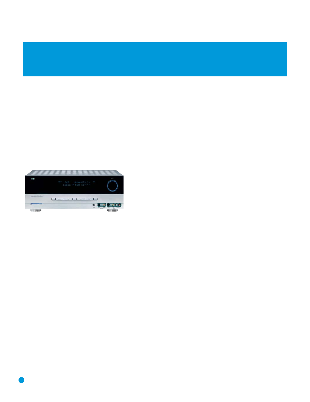
Thank you for choosing Harman Kardon®!
In the years since Harman Kardon invented the high-fidelity receiver,
we have taken to heart the philosophy of bringing the joy of home
entertainment to as many people as possible, adding performance and
ease-of-use features that enhance the home entertainment experience.
In the years since our first single-channel component was introduced,
Harman Kardon has offered a number of receiver models, each an
improvement upon its predecessors, leading to the AVR 144, a
5.1-channel digital audio/video receiver that offers a wealth of listening
and viewing options, all in an affordable elegant package.
AVR 144 5.1-Channel Audio/Video Receiver
Audio Section
• 30 Watts x 5, five channels driven at full power at 8 ohms,
20Hz – 20kHz, <0.07% THD, (surround modes); 150 watts total
• 40 Watts x 2, two channels driven at full power at 8 ohms,
20Hz – 20kHz, <0.07% THD, (surround off mode); 80 watts total
• High current capability, ultrawide-bandwidth amplifier design with low
negative feedback
• All-discrete amplifier circuitry
• Dual independent power supplies, for front and surround channels
• Triple crossover bass management
®
• 24-Bit, twin-core Cirrus Logic
• 192kHz/24-bit D/A conversion
• Sampling upconversion to 96kHz
CS 49510 DSP processor
To obtain the maximum enjoyment from your new receiver, we urge you
to read this manual and refer back to it as you become more familiar
with its features and their operation.
If you have any questions about this product, its installation or its operation, please contact your retailer or customer installer, or visit our Web
site at www.harmankardon.com.
Surround Modes
• Dolby®Digital
®
• Dolby Pro Logic
• Dolby Virtual Speaker Version 2 (Reference two- or three-speaker;
Wide two-, three-, four- or five-speaker)
• Dolby Headphone Version 2
®
(5.1; DTS Stereo)
• DTS
• DTS 96/24
• DTS Neo:6
®
• Logic 7
• Hall 1 and Hall 2
• Theater
• 5-Channel Stereo
• Surround Off (DSP or Analog Bypass)
II (Movie, Music and Game)
™
(DTS Stereo)
®
(Cinema 3- or 5-channel; Music 5-channel)
(Cinema, Music and Enhance)
6
Page 7

INTRODUCTION
Audio Inputs
• AM/FM tuner
• CD
• Tape
• 6-Channel direct
Audio/Video Inputs (With S-Video)
• Video 1
• Video 2
• Video 3
• DVD
• Two 100MHz assignable component video inputs
Digital Audio Inputs
• Coaxial: Two rear-panel/one front-panel
• Optical: Two rear-panel/one front-panel
Outputs
• Subwoofer output
• Tape (analog audio)
• Video 1 (analog audio and video)
• Video Monitor (composite, S-video and component)
• Headphone
Ease of Use
• On-screen display with composite and S-video; choice of blue or
black background
• Two-line dot-matrix front-panel display
• Color-coded connections
• Programmable seven-device main remote control
• Source input renaming
• A/V Sync Delay
Supplied Accessories
The following accessory items are supplied with the AVR 144. If any
of these items are missing, please contact Harman Kardon customer
service at www.harmankardon.com.
• System remote control
• AM loop antenna
• FM wire antenna
• Three AAA batteries
• Two covers for front-panel jacks
7
Page 8

FRONT-PANEL CONTROLS
Main Power Switch: This is a mechanical switch that turns the
power supply on or off. It is usually left pressed in (On position) at all
times, and cannot be turned on using the remote control.
Standby/On Switch: This is an electrical switch that turns the
receiver on for playback, or leaves it in standby mode for quick turn-on
using this switch or the remote control.
Power Indicator: This LED has three possible modes. When main
power is turned off, the LED is dark and the receiver won’t respond to
any button presses. When main power is turned on, but before the
Standby/On Switch is used, the LED turns amber to indicate that the
receiver is in Standby mode and ready to be turned on. When the
receiver is turned on, the LED turns blue.
Source Select: Press this button to select a source device, which is
a component where a playback signal originates, e.g., DVD, CD, cable
TV, satellite or HDTV tuner.
Source Indicators: The name of the current source input lights up.
The indicated input changes each time the Source Select Button is
pressed.
Volume Knob: Turn this knob to raise or lower the volume, which will
be shown in decibels (dB) in the Message Display.
Message Display: Various messages appear in this two-line display
in response to commands. When the on-screen display menu system
(OSD) is in use, the message OSD ON will appear to remind you to
check the video display.
Tuner Band: Press this button to select the tuner as the source, or to
switch between the AM and FM bands.
Tuning: Press either side of this button to tune a radio station.
Tuning Mode: This button toggles between manual (one frequency
step at a time) and automatic (seeks frequencies with acceptable signal
strength) tuning mode. It also toggles between stereo and mono modes
when an FM station is tuned.
Preset Stations: Press this button to select a preset radio station.
Headphone Jack: Plug a 1/4" headphone plug into this jack for
private listening.
Surround Mode: Press this button to select a type of surround
sound (e.g., multichannel) mode. Choose from the Dolby modes, DTS
modes, Logic 7 modes, DSP modes or Stereo modes.
Surround Select: After you have selected the desired type of sur-
round mode, press this button to select a specific variant of that type
of mode.
Surround Mode Indicators: One or more of these icons may light
up as you select different surround modes. The Message Display also
indicates the surround mode.
Analog Audio, Video and Digital Audio Inputs: Connect a
source component that will only be used temporarily to these jacks,
such as a camera or game console. Remember to select only one type
of audio and one type of video connection.
Speaker/Channel Input Indicators: The box icons indicate
which speaker positions you have configured, and the size (frequency
range) of each speaker. When a digital audio input is used, letters will
light inside the boxes to indicate which channels are present in the
incoming signal.
8
Page 9

9
Page 10

REAR-PANEL CONNECTIONS
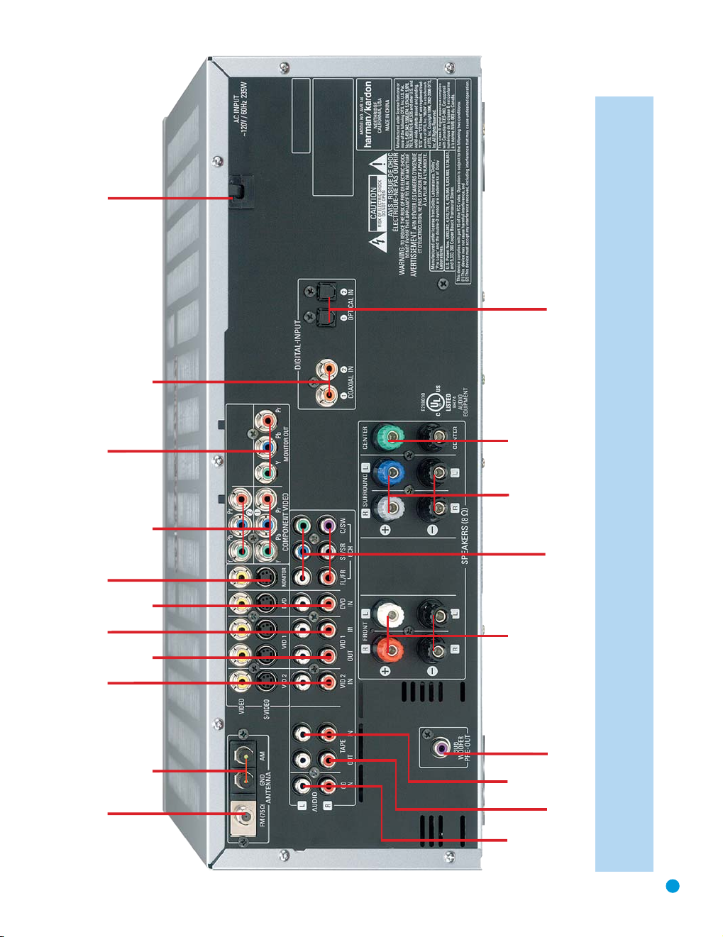
AM and FM Antenna Terminals: Connect the included AM and
FM antennas to their respective terminals for radio reception.
Front, Center and Surround Speaker Outputs: Use two-
conductor speaker wire to connect each set of terminals to the correct
speaker. Remember to observe the correct polarity (positive and negative
connections). Always connect the positive lead to the colored terminal
on the receiver and the red terminal on the speaker. Connect the negative
lead to the black terminal on both the receiver and the speaker. See the
10
Page 11
FM Antenna
AM Antenna
Video 2
A/V
Inputs
Video 1
A/V
Outputs
Video 1
A/V
Inputs
Video
Monitor
Outputs
DVD A/V
Inputs
Component Video
Inputs (1 & 2)
Component Video
Monitor Outputs
AC Power
Cord
Coaxial Digital
Audio Inputs
(1 & 2)
Subwoofer
Output
Front
Speaker
Outputs
Surround
Speaker
Outputs
6-Channel
Inputs
Center
Speaker
Outputs
Optical Digital
Audio Inputs (1 & 2)
CD
Inputs
Tape
Outputs
Tape
Inputs
NOTE: To make it easier to follow the instructions throughout the manual that refer to this illustration, a copy of this page may be downloaded from the Product Support section at
www.harmankardon.com.
11
Page 12

REMOTE CONTROL FUNCTIONS
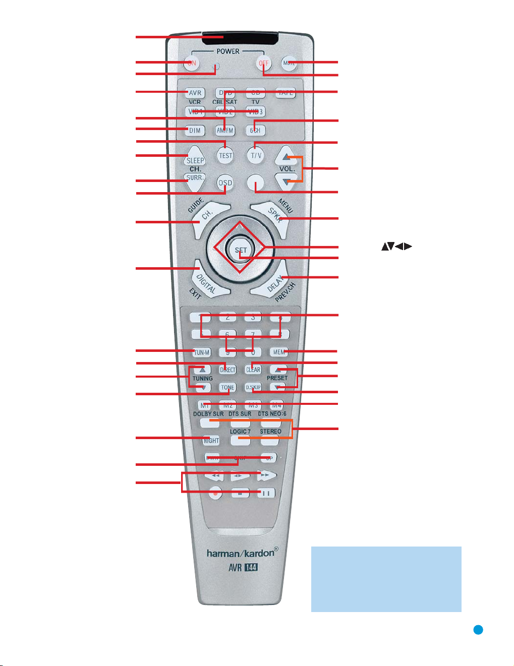
The AVR 144 remote is capable of controlling seven devices, including
the AVR itself. During the installation process, you may program the
codes for each of your source components into the remote. Each time
you wish to use the codes for any component, you will need to first
press the Selector Button for that component. This changes the button
functions to the appropriate codes for that product.
Each Input Selector has been preprogrammed to control certain types
of components, with only the codes specific to each brand and model
changing, depending on which product code is programmed. The
device types programmed into each selector may not be changed.
DVD: Controls DVD players and recorders.
CD: Controls CD players and recorders.
Tape: Controls cassette decks.
Video 1: Controls VCRs, TiVo
®
and DVRs.
Video 2: Controls cable and satellite television set-top boxes.
Video 3: Controls televisions and other video displays.
For example, if you have inserted a disc in your CD player and you
would like to skip ahead three tracks, but you then find that the volume
is too loud, you would follow this procedure:
1. Press the CD Input Selector to switch to the codes that control your
CD player.
2. Press the Play Button (in the Transport Controls section) if the disc is
not already playing.
3. Press the Skip Up Button three times to advance three tracks.
4. Press the AVR Button so that you can access the Volume Controls.
5. Press the Volume Down Button until the volume level is satisfactory.
Any given button may have different functions, depending on which
component is being controlled. Some buttons are labeled with these
functions. For example, the Sleep and DSP Surround Buttons are
labeled for use as Channel Up/Down Buttons when controlling a television or cable box. See Table A8 in the appendix for listings of the
different functions for each type of component.
IR Transmitter Lens: As buttons are pressed on the remote,
infrared codes are emitted through this lens. Make sure it is pointing
toward the component being operated.
Power On Button: Press this button to turn on the AVR or another
device. The Master Power Switch on the AVR 144’s front panel must
first have been switched on.
Mute Button: Press this button to mute the AVR 144’s speaker
and headphone outputs temporarily. To end the muting, press this button
or adjust the volume. Muting is also canceled when the receiver is
turned off.
Program Indicator: This LED lights up or flashes in one of three colors
as the remote is programmed with codes.
12
Power Off Button: Press this button to turn off the AVR 144 or
another device.
AVR Selector: Press this button to switch the remote to the codes
that operate the receiver.
Input Selectors: Press one of these buttons to select a source
device, which is a component where a playback signal originates, e.g.,
DVD, CD, cable TV, satellite or HDTV tuner. This will also turn on the
receiver and switch the remote to the codes that operate the source
device.
AM/FM Button: Press this button to select the tuner as the source,
or to switch between the AM and FM bands.
6-Channel Input Selector: Press this button to select the 6-
Channel Inputs as the audio source. The receiver will use the video input
and remote control codes for the last-selected video source.
Dim: Press this button to partially or fully dim the front-panel display.
Test Tone: Press this button to activate the test tone for output-level
calibration.
TV/Video: This button has no effect on the receiver, but is used to
switch video inputs on some video source components.
Sleep Button: Press this button to activate the sleep timer, which
shuts off the receiver after a programmed period of time of up to
90 minutes.
Volume Controls: Press these buttons to raise or lower the volume,
which will be shown in decibels (dB) in the Message Display.
DSP Surround: Press this button to select a DSP surround mode
(Hall 1, Hall 2, Theater).
On-Screen Display (OSD): Press this button to activate the on-
screen menu system.
Channel Level: Press this button to set the output levels for each
channel so that all speakers sound equally loud at the listening position.
Usually this is done while playing an audio selection, such as a favorite CD,
as described in the Initial Setup section.
Speaker Setup: Press this button to configure speaker sizes, that is,
the low-frequency capability of each speaker. Usually this is done using
the on-screen menu system, as described in the Initial Setup section.
Navigation (⁄/¤/‹/›) and Set Buttons: These buttons
are used together to make selections within the on-screen menu system, or when accessing the functions of the four buttons surrounding
this area of the remote – Channel Level, Speaker Setup, Digital Input
or Delay.
Digital Input Select: Press this button to select the specific digital
audio input (or analog audio input) you used for the current source.
Delay: Press this button to set delay times that compensate for placing
the speakers at different distances from the listening position, or to
resolve a “lip sync” issue that may be caused by digital video processing.
(continued on p. 14)
Page 13
IR Transmitter Lens
Program Indicator
Power On
AVR Selector
AM/FM
Dim
Test Tone
Sleep
DSP Surround
On-Screen Display
Channel Level
Digital Input
Tuning Mode
Direct Station Entry
Tuning
Tone Mode
Night Mode
Track Skip
Transport Controls
Power Off
Mute
Input Selectors
6-Channel Input Selector
TV/Video
Volume Control
(Not Used)
Speaker Setup
Set
Numeric Keys
Delay
Memory
Clear
Preset Stations Selectors
Disc Skip
Macros
Surround Mode Selectors
Navigation
NOTE: To make it easier to follow the instruc-
tions throughout the manual that refer to this
illustration, a copy of this page may be downloaded from the Product Support section at
www.harmankardon.com.
13
Page 14

REMOTE CONTROL FUNCTIONS
This is done using the on-screen menu system, as described in the
Initial Setup section.
Numeric Keys: Use these buttons to enter radio station frequencies
when using the tuner (after pressing the Direct Button), or to select station
presets.
Tuning Mode: This button toggles between manual (one frequency
step at a time) and automatic (seeks frequencies with acceptable signal
strength) tuning mode. It also toggles between stereo and mono modes
when an FM station is tuned.
Memory: After you have tuned a particular radio station, press this
button, then the numeric keys, to save that station as a radio preset.
Tuning: Press these buttons to tune a radio station. Depending on
whether the tuning mode has been set to manual or automatic, each
press will either change one frequency step at a time, or seek the next
frequency with acceptable signal strength.
Direct: Press this button before using the Numeric Keys to directly
enter a radio station frequency.
Clear: Press this button to clear a radio station frequency you have
started to enter.
Preset Stations Selector: Press these buttons to select a preset
radio station.
Tone Mode: Press this button to access the tone controls (bass and
treble). Use the Navigation Buttons to make your selections.
Disc Skip: This button has no effect on the receiver, but is used with
some optical disc changers to skip to the next disc.
Macros: These buttons may be programmed to execute long com-
mand sequences with a single button press. They are useful for programming the command to turn on or off all of your components, or for
accessing specialized functions for a different component than you are
currently operating.
Surround Mode Selectors: Press any of these buttons to select
a type of surround sound (e.g., multichannel) mode. Choose from the
Dolby modes, DTS modes, Logic 7 modes or Stereo modes. Each
press of a button will cycle to the next available variant of that mode.
Not all modes or mode groups are available with all sources.
Night Mode: Press this button to activate Night mode with specially
encoded Dolby Digital discs or broadcasts. Night mode compresses the
audio so that louder passages are reduced in volume to avoid disturbing
others, while dialogue remains intelligible.
Track Skip: These buttons have no effect on the receiver, but are
used with many source components to change tracks or chapters.
Transport Controls: These buttons have no effect on the receiver,
but are used to control many source components. By default, when the
remote is operating the receiver, these buttons will control a DVD player.
14
Page 15

INTRODUCTION TO HOME THEATER
The AVR 144 may be the first multichannel surround sound receiver you
have owned. Although it has more connections and features than older
two-channel receivers, many of the principles are similar and the new
concepts are easy to understand. This introductory section will help you
to familiarize yourself with the basic concepts, which will make setup and
operation smoother.
If you are already familiar with home theater, you may skip this section
and proceed to the Connections section on page 16.
Typical Home Theater System
A home theater typically includes your audio/video receiver, which controls the system; a DVD player; a source component for television broadcasts, which may be a cable box, a satellite dish receiver, an HDTV tuner
or simply an antenna connected to the TV; a video display (television);
and loudspeakers.
All of these components are connected using various types of cables for
audio and video signals.
Multichannel Audio
The main benefit of a home theater system is that several loudspeakers
are used in various locations around the room to produce “surround
sound.” Surround sound helps to immerse you in the musical or film
presentation for increased realism.
The AVR 144 may have up to five speakers connected directly to it
(plus a subwoofer). Each speaker is powered by its own amplifier channel inside the receiver. When more than two speakers are used, it is
called a multichannel system.
Front Left and Right – The main speakers are used the same way
•
as in a two-channel system. However, you may notice that in many
surround modes, these speakers are used more for ambient sound
while the main action is moved to the center speaker.
• Center – The center speaker is usually placed above or below the
video screen, and is used mostly for dialogue in movies and television
programs. This placement allows the dialogue to originate near the
actors’ faces, for a more natural sound.
• Surround Left and Right – The surround speakers are used to
improve directionality of ambient sounds. In addition, by using more
loudspeakers in the system, more dynamic soundtracks may be
played without risk of overloading any one speaker.
Many people expect the surround speakers to play as loudly as the
front speakers. Although all of the speakers in the system will be calibrated to sound equally loud at the listening position, most artists use
the surround speaker for ambient effects only, and they program their
materials to steer very little sound to these speakers.
Subwoofer – A subwoofer is a special-purpose speaker designed
•
to play only the lowest frequencies (the bass). It may be used to
augment smaller, limited-range satellite speakers used for the other
channels. In addition, many digital-format programs, such as movies
recorded in Dolby Digital, contain a special low-frequency effects
(LFE) channel which is directed only to the subwoofer. The LFE channel packs the punch of a rumbling train or airplane, or the power of
an explosion, adding realism and excitement to your home theater.
Many people use two subwoofers, placed on the left and right sides
of the room, for additional power and even distribution of the sound.
Surround Modes
There are different theories as to the best way to present surround
sound and to distribute soundtrack information among the various
speakers. A variety of algorithms have been developed in an effort to
accurately reproduce the way we hear sounds in the real world. The
result is a rich variety of surround mode options. Some modes are
selected automatically, depending on the signal being received from the
source. In many cases, you may select a surround mode manually.
Several companies have taken surround sound in slightly differing directions. It is helpful to group the numerous surround modes either by their
brand name, or by using a generic name:
Dolby Laboratories, Inc. Modes – Dolby Digital, Dolby Pro Logic II,
•
Dolby Virtual Speaker, Dolby Headphone
• DTS Modes – DTS, DTS Neo:6, DTS 96/24
• Harman International (Harman Kardon’s Parent Company) –
Logic 7
• DSP Modes – Generic modes that include Hall 1, Hall 2 and Theater
• Stereo Modes – Generic modes that expand upon conventional two-
channel stereo, including DSP Surround Off, Analog Bypass Surround
Off and 5-Channel Stereo
Table 4 on pages 39 – 41 contains detailed explanations of the differences between the various mode groups, and the mode options available within each group. Digital modes, such as Dolby Digital and DTS,
are only available with specially encoded programs, such as DVDs and
digital cable or satellite television. Other modes may be used with various digital and analog signals to create a different surround presentation, or to use a different number of speakers. Surround mode selection
depends upon the number of speakers in your system, the materials
you are watching or listening to, and your personal tastes. Feel free to
experiment.
15
Page 16
CONNECTIONS
Subwoofer
Pre-out
12 3
+
Audio Connections
Left Right
Front (FL/FR)
Center (C)
Surround (SL/SR)
Subwoofer (SUB)
Digital Audio Connections
Coaxial
Optical Input
Video Connections
Component Y Pb Pr
Composite
S-Video
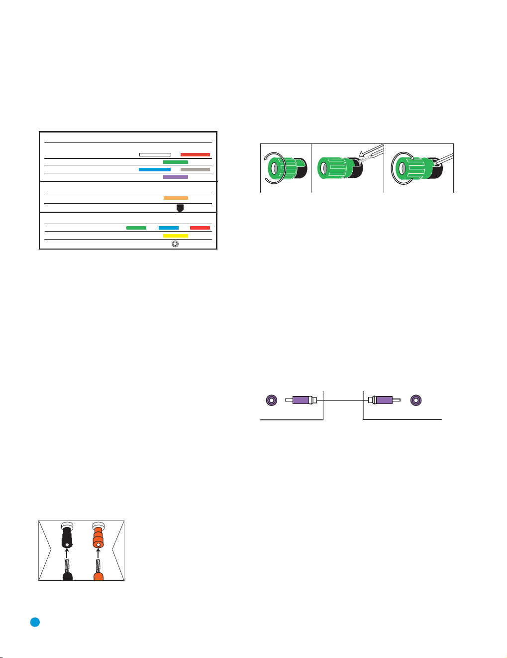
There are different types of audio and video connections used to connect the receiver to the speakers and video display, and to connect
the source devices to the receiver. To make it easier to keep them all
straight, the Consumer Electronics Association (CEA) has established a
color-coding standard. Table 1 may be helpful to you as a reference
while you set up your system.
Table 1–Connection Color Guide
Types of Cables
This section will briefly review different types of cables and connections
that you may use to set up your system.
Speaker Connections
Speaker cables carry an amplified signal from the receiver’s speaker
terminals to each loudspeaker. Speaker cables contain two wire
conductors, or leads, inside plastic insulation. The two conductors are
usually differentiated in some way, by using different colors, or stripes,
or even by adding a ridge to the insulation. Sometimes the actual wires
are different, one being copper red and the other silver.
The differentiation is important because each speaker must be connected
to the receiver’s speaker-output terminals using two wires, one positive
(+) and one negative (–). This is called speaker polarity. It’s important to
maintain the proper polarity for all speakers in the system. If some speakers
have their negative terminals connected to the receiver’s positive
terminals, performance can suffer, especially for the low frequencies.
Always connect the positive terminal on the loudspeaker, which is usually
colored red, to the positive terminal on the receiver, which is colored as
shown in the Connection Color Guide (Table 1). Similarly, always connect the black negative terminal on the speaker to the black negative
terminal on the receiver.
The AVR 144 uses binding-post speaker
terminals that can accept banana plugs
Figure 1 – Binding-Post Speaker Terminals With Banana Plugs
16
or bare-wire cables.
Banana plugs are simply plugged into the
hole in the middle of the terminal cap.
See Figure 1.
Bare wire cables are installed as follows (see Figure 2):
1. Unscrew the terminal cap until the pass-through hole in the collar is
revealed.
2. Insert the bare end of the wire into the hole.
3. Screw the cap back into place until the wire is held snugly.
Figure 2 – Binding-Post Speaker Terminals With Bare Wires
Subwoofer
The subwoofer is a specialized type of loudspeaker that is usually connected in a different way. The subwoofer is used to play only the low
frequencies (bass), which require much more power than the other
speaker channels. In order to obtain the best results, most speaker
manufacturers offer powered subwoofers, in which the speaker contains
its own amplifier on board. Sometimes the subwoofer is connected to
the receiver using the front left and right speaker outputs, and then the
front left and right speakers are connected to terminals on the subwoofer. More often, a line-level (nonamplified) connection is made
from the receiver’s Subwoofer Output to a corresponding jack on the
subwoofer, as shown in Figure 3.
Although the subwoofer output looks similar to the analog audio jacks
used for the various components, it is filtered and only allows the low
frequencies to pass. Don’t connect this output to your other devices.
Although doing so won’t cause any harm, performance will suffer.
Figure 3 – Subwoofer
Connecting Source Devices to the AVR
The AVR 144 is designed to process audio and video input signals,
playing back the audio and displaying the video on a television or monitor connected to the AVR. These signals originate in what are known as
“source devices,” including your DVD player, CD player, DVR (digital
video recorder) or other recorder, tape deck, game console, cable or
satellite television box or MP3 player. Although the tuner is built into the
AVR, it also counts as a source, even though no external connections
are needed, other than the FM and AM antennas.
Separate connections are required for the audio and video portions of
the signal. The types of connections used depend upon what’s available
on the source device, and for video signals, the capabilities of your
video display.
Page 17
CONNECTIONS
S-video
cable
Composite
video cable
Composite video
Multichannel
analog audio
cable (RCA)
Front Surround Center
Subwoofer
A
Optical
Optical digital
audio cable
Coaxial
Coaxial digital
audio cable
Audio Connections
There are two formats for audio connections: digital and analog. Digital
audio signals are of higher quality, and are required for listening to
sources encoded with digital surround modes, such as Dolby Digital and
DTS. There are two types of digital audio connections commonly used:
coaxial and optical. Either type of digital audio connection may be used
for each source device, but never both simultaneously for the same
source. However, it’s okay to make both analog and digital audio connections at the same time, to the same source.
Digital Audio
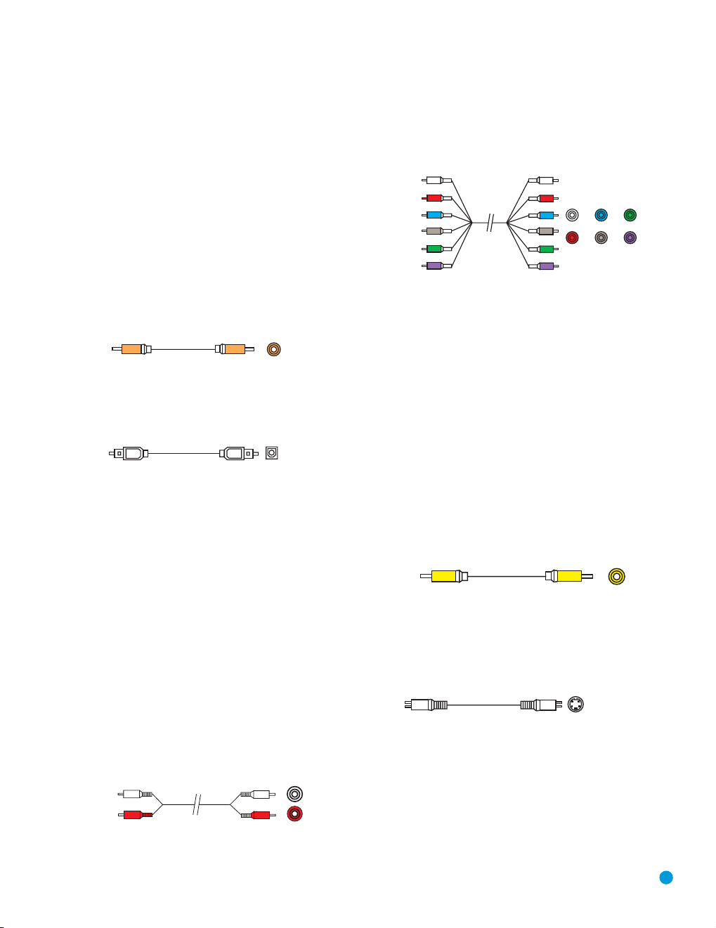
Coaxial digital audio jacks are usually color-coded in orange. Although
they look similar to analog jacks, they should not be confused, and you
should not connect coaxial digital audio outputs to analog inputs or
vice versa. See Figure 4.
Figure 4 – Coaxial Digital Audio
Optical digital audio connectors are normally covered by a shutter to
protect them from dust. The shutter opens as the cable is inserted.Input
connectors are color-coded using a black shutter. See Figure 5.
Figure 5 – Optical Digital Audio
Due to the nature of digital signals as binary bits, they aren’t subject
to signal degradation the way analog signals are. Therefore, the quality
of coaxial and optical digital audio connections should be the same,
although it is important to limit the length of the cable. Whichever type of
connection you choose, Harman Kardon recommends that you always
select the highest quality cables available within your budget.
Multichannel analog connections are used with advanced sources where
the digital content is copy-protected and all surround processing is performed inside the source. These types of connections are usually used
with DVD-Audio, SACD, Blu-ray Disc, HD-DVD and other advanced
players. See Figure 7.
Figure 7 – Multichannel Analog Audio
Video Connections
Although some sources produce an audio signal only (e.g., CD player,
tape deck), many sources output both audio and video signals (e.g.,
DVD player, cable television box, HDTV tuner, satellite box, VCR, DVR).
In addition to the audio connection, you will need to connect one type of
video connection for each source (never more than one at the same
time for any source).
There are three types of analog video connections: composite video,
S-video and component video.
Composite video is the basic connection most commonly available.
The jack is usually color-coded in yellow, and looks like an analog audio
jack, although it is important never to confuse the two. Do not plug a
composite video cable into an analog or coaxial digital audio jack, and
vice versa. Both the chrominance (color) and luminance (intensity)
components of the video signal are transmitted using a single cable.
See Figure 8.
Analog Audio
Analog connections require two cables, one for the left channel (white)
and one for the right channel (red). These two cables are often attached
to each other for most of their length. See Figure 6.
Most sources that have digital audio jacks also have analog audio jacks,
although some older types of sources, such as tape decks, have only
analog jacks. For sources that are capable of both digital and analog
audio, you may wish to make both connections. If you wish to record
materials from DVDs or other copy-protected sources, you will only be
able to do so using analog connections. Remember to comply with all
laws regarding copyright, if you choose to make a copy for your own
personal use.
nalog audio
cable (RCA)
Figure 6 – Analog Audio
L
R
Figure 8 – Composite Video
S-video, or “separate” video, transmits the chrominance and luminance
components using separate wires contained within a single cable. The
plug on an S-video cable contains four metal pins, plus a plastic guide
pin. Be careful to line up the plug correctly when you insert it into the
jack on the receiver, source or video display. See Figure 9.
Figure 9 – S-Video
Component video separates the video signal into three components –
one luminance (“Y”) and two subsampled color signals (“Pb” and “Pr”) –
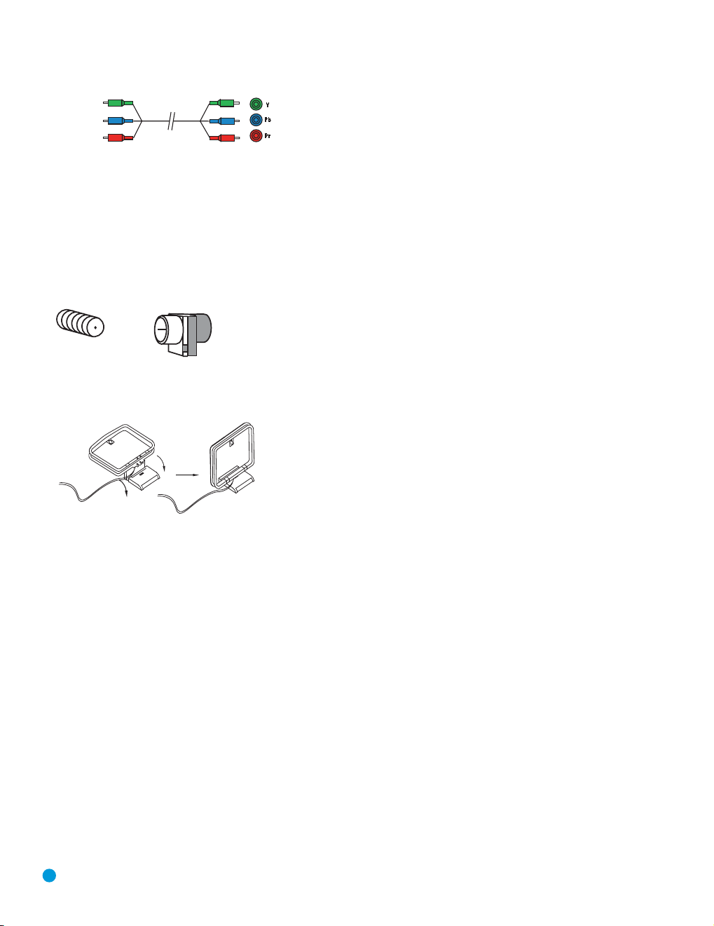
that are transmitted using three separate cables. The “Y” cable is colorcoded green, the “Pb” cable is colored blue and the “Pr” cable is colored red. See Figure 10.
17
Page 18
CONNECTIONS
Component
video cable
Figure 10 – Component Video
If it’s available on your video display, component video is recommended as the best quality connection, followed by S-video and then
composite video.
Antennas
The AVR 144 uses separate terminals for the included FM and AM
antennas that provide proper reception for the tuner.
The FM antenna uses a 75-ohm F-connector. See Figure 11.
Figure 11 – FM Antenna
The AM loop antenna needs to be assembled. Then connect the two
leads to the screw terminals on the receiver. See Figure 12.
Figure 12 – AM Antenna
18
18
Page 19
SPEAKER PLACEMENT
110 °
150°
110 °
150°
30° 30°
FL
SR
Alternate Placement
for Side Surround
Left Speaker
Alternate Placement
for Side Surround
Right Speaker
FR
SUB
C
SL
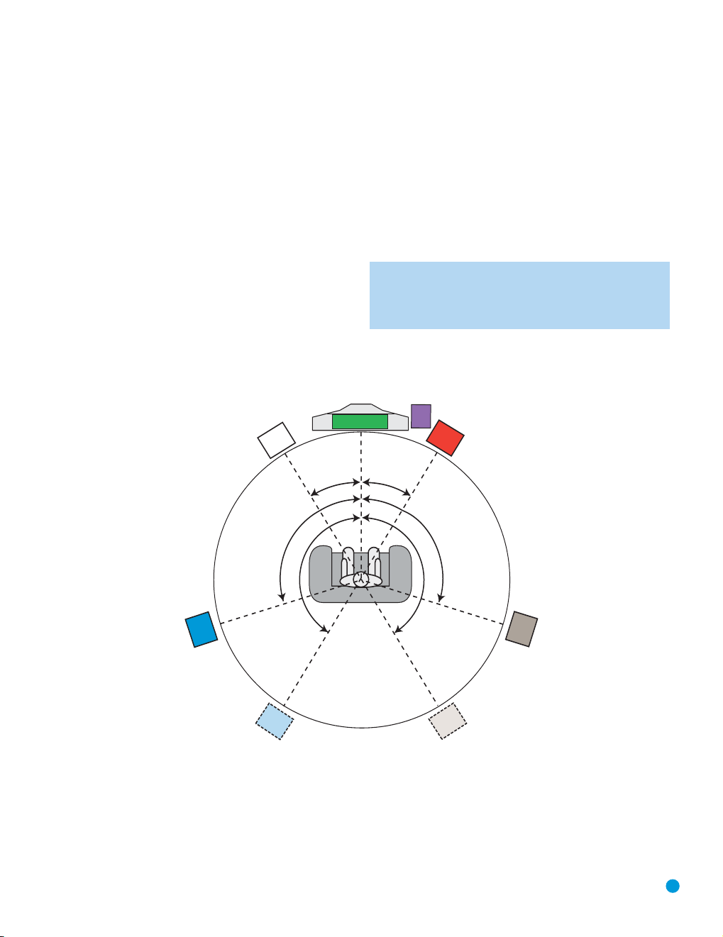
Before you begin to connect cables, it is important to set up your
speakers in their correct locations in the room.
Optimally, the speakers should be placed in a circle with the listening
position at its center. The distance from the listening position to the
video display forms the radius of the circle.
The speakers should be angled so that they directly face the listening
position.
The center speaker is placed either on top of, below or mounted on the
wall above or below the video display screen.
The front left and right speakers are placed along the circle, about 30
degrees from the center speaker and angled toward the listener.
It is best to place the front left/right and center speakers as close to the
same height as possible, preferably at about the same height as the listener’s ears. In any event, the center speaker should be no more than
two feet above or below the left/right speakers.
The side surround speakers should be placed 110 degrees from the
center speaker, that is, slightly behind and angled toward the listener. If
this isn’t feasible, place the surround speakers behind the listener, with
each surround speaker facing the opposite-side front speaker. The surround speakers may be placed a little higher than the listener’s ears.
The subwoofer’s location is less critical, since low-frequency sounds are
omnidirectional. Placing the subwoofer close to a wall or in a corner will
reinforce the low frequencies, and may create a “boomy” sound. You
may wish to experiment over time by placing the subwoofer where the
listener normally sits and then walking around the room until the low
frequencies sound best. Place the subwoofer in that spot.
NOTE: Your receiver will sound its best when the same model
loudspeaker is used for all positions (other than the subwoofer).
If that isn’t possible, try to use speakers made by the same
manufacturer.
19
Figure 13 – Speaker Placement
19
Page 20

INSTALLATION
You are now ready to connect your various components to your receiver.
Before beginning, make sure that all components, including the AVR 144,
are turned completely off and their power cords are unplugged. Don’t
plug any of the power cords back in until you have finished
making all of your connections.
Remember that your receiver generates heat while it is playing. Select a
location that leaves several inches of space on all sides of the receiver. It
is preferable to avoid completely enclosing the receiver inside a cabinet.
It is also preferable to stack components on separate shelves rather
than directly on top of the receiver. Some surface finishes are delicate.
Try to select a location with a sturdy surface finish.
Step One – Connect the Speakers
If you have not yet done so, place your speakers in the listening room
as described in the Speaker Placement section above.
Connect the center, front left, front right, surround left and surround right
loudspeakers to the corresponding speaker terminals on the AVR 144.
Remember to maintain the proper polarity by always connecting the
positive and negative terminals on each speaker to the positive and
negative terminals on the receiver. Use the Connection Color Guide
on page 16 as a reference. See Figure 14.
Figure 14 – Speaker Connections
Step Two – Connect the Subwoofer
Connect the Subwoofer Output on the AVR 144 to the line-level input on
your subwoofer. See Figure 15. Consult the manufacturer’s guide for the
subwoofer for addition7.2(Sn2re a locre 14.)]TJ6.6552 0 0 6.6552 88131 c968.4166 (See Figu –)-480.4( the Subwoaker Connenish.)]TJ/F3 1 Tf11.6467 0 0 11.3 0 50 88.324 820.3891 Tm[(Step )3hreep One – Connect the
20
20
Page 21
INSTALLATION
We recommend connecting your various sources using the connections
NOTE: It’s possible for a source to use none of the connections
named for that source. For example, you might connect your
DVD player to the Component Video 1 inputs and the Coax 1
digital audio input. However, we will refer to this source as
“DVD”, and in Step Five of the Initial Setup section you will program the receiver so that these connections are assigned to the
DVD source. When you select “DVD” as your source using the
front panel or the remote, the correct connections for your DVD
player will be used.
Device Type AVR 144 Source Input Audio Connections Video Connections
VCR, DVR, PVR, Video 1 • Video 1 Analog (inputs and outputs) •
TiVo or other and or Video 1 composite video
audio/video recorder • Any one available coaxial or optical • For recording, use Video 1 S-video or
Cable TV, satellite, Video 2 • Video 2 Analog and •
HDTV or other • Optical 1 S-video, Video 2 composite video
device that delivers
television programs
TV, game console, Video 3 (front-panel jacks) • Video 3 Analog and •
camera or other •
audio/video device
DVD Audio/Video, DVD • DVD Analog • Component Video 1
SACD, HD-DVD, • 6-Channel inputs (optional) and
Blu-ray Disc • Coax 1
CD player CD • CD Analog and • Not required
CDR, MiniDisc, Tape • Tape Analog (inputs and outputs) and • Not required
cassette • Any one available coaxial or optical
digital audio input composite video output, and do not use
Either
Coax 3 or Optical 3
• Any one available coaxial or optical
digital audio input
digital audio input
shown in Table 2 below in order to simplify programming your receiver
and remote control. However, you may connect any device to any
source input.
One
of component Video 2, Video 1 S-video
component video connections at all
One
of component Video 2, Video 2
One
of component Video 2, Video 3 S-video
or
Video 3 composite video
Table 2 – Recommended Source Component Connections
Video 1 Source
Since this source includes audio and video recording output jacks, it is
best suited to a video recorder, such as your VCR or DVR.
Referring to Table 2, connect your recorder to the Video 1 Analog Audio
inputs and outputs and to any available Coax or Optical digital audio
input. See Figure 17. Use either the Video 1 S-video or composite
video input and output if you wish to make recordings. If you don’t plan
on recording, you may use the Component Video 2 inputs.
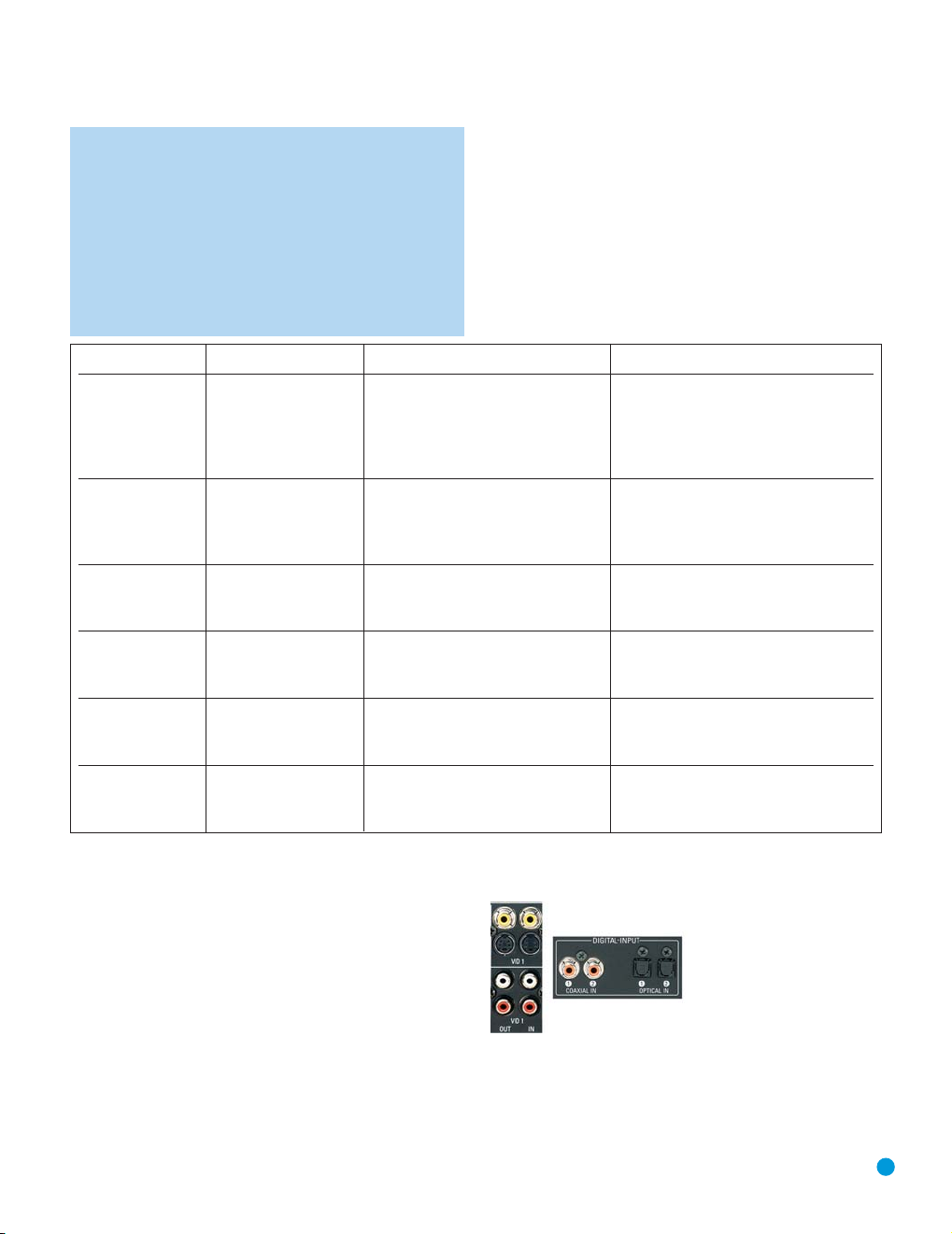
Figure 17 – Video 1 A/V Inputs and Outputs, and Digital Audio Inputs
Remember to connect the audio and video
recorder to the Video 1 or digital audio
input
audio and video
jacks on your recorder to the Video 1
output
input
jacks on the AVR, and the
jacks on the AVR.
jacks on your
output
21
Page 22
INSTALLATION
NOTES:
1. It isn’t possible to make recordings using component video
connections. Keep this in mind as you connect other source
devices that you may wish to make recordings from.
2. The AVR 144 does not have any digital audio outputs. If you
wish to make recordings, your source must be connected to
any of the AVR 144’s analog audio inputs, and your recorder
must be connected to either the Video 1 or Tape Analog
Audio Outputs. The AVR 144 will not convert a digital audio
input signal to analog.
Video 2 Source
The Video 2 source is used only for playback, never recording. The
AVR 144 remote control is programmed to operate many brands and
models of cable and satellite television devices, and we recommend
connecting your cable or satellite set-top box to this source.
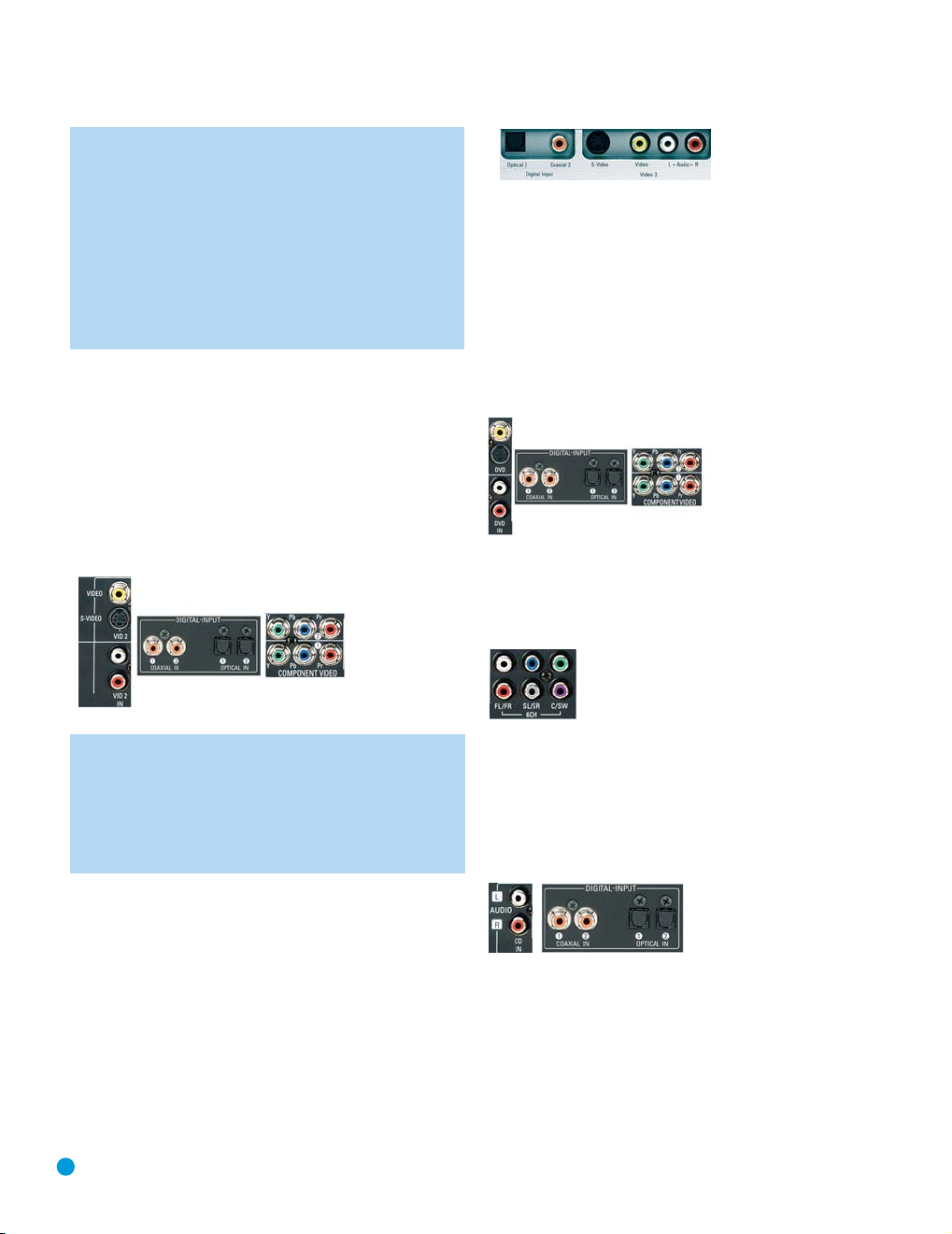
Referring to Table 2, connect your set-top box to the Video 2 Analog
Audio inputs
the Component Video 2 inputs. Otherwise, connect the set-top box’s
S-video or composite video output to the matching Video 2 video input.
See Figure 18.
and to the Optical 1 Digital Audio input. If possible, use
Figure 19 – Video 3 A/V and Digital Audio Inputs
DVD
The DVD source is used for a DVD player. If you have a more advanced
multichannel device, such as a Blu-ray Disc or HD-DVD player, connect
it to the DVD source.
Referring to Table 2, connect your DVD player to the DVD Analog
Audio inputs and to the Coaxial 1 Digital Audio input. If possible, use
the Component Video 1 inputs. Otherwise, connect the DVD player’s
S-video or composite video output to the matching DVD video input.
See Figure 20.
Figure 20 – DVD A/V, Digital Audio and Component Video Inputs
If your DVD player plays multichannel lossless discs, such as SACD or
DVD-Audio, you will also need to connect the 6-channel analog audio
outputs on the DVD player to the 6-channel analog audio inputs on the
receiver in order to enjoy these discs to their fullest. See Figure 21.
Figure 18 – Video 2 A/V, Digital Audio and Component Video Inputs
NOTE: If you receive your television programming using your TV
with an antenna or direct cable connection, then you will need
to connect the analog audio (if available on your TV) outputs to
the Video 2 Analog Audio inputs. Do not connect any video output on the television set to any video input on the receiver. See
Step Five for information on connecting the receiver’s video
monitor outputs to the television.
Video 3 Source
The Video 3 source is used only for playback, never recording. It is also
generally reserved for components that are only temporarily connected
to the receiver, such as cameras and game consoles. When not in use,
you may place the supplied covers over the front-panel Video 3 jacks
for a cleaner appearance. Simply snap the covers in place. When you
wish to use the jacks, gently press on the left side of each cover to pivot
it out for removal.
Referring to Table 2, connect your camera or game console to the
Video 3 Analog Audio inputs
digital audio input. If possible, use the Component Video 2 inputs.
Otherwise, connect the component’s S-video or composite video
output to the matching Video 3 video input. See Figure 19.
22
and to either the Coaxial 3 or Optical 3
Figure 21 – 6-Channel Analog Audio Inputs
CD
The CD source is used for a strictly audio device, such as a CD player.
Referring to Table 2, connect your CD player to the CD Analog Audio
inputs and to the Coaxial 2 or Optical 2 Digital Audio input. See
Figure 22.
Figure 22 – CD Audio Inputs and Digital Audio Inputs
No video connections are made, although if your system has unusual
requirements, you may connect a video device using component video
outputs to the Component Video 2 inputs on the receiver, if those jacks
are not in use by another device.
Page 23
INSTALLATION
Tape
The Tape source is used for audio-only recorders, such as a CDR,
MiniDisc or cassette deck.
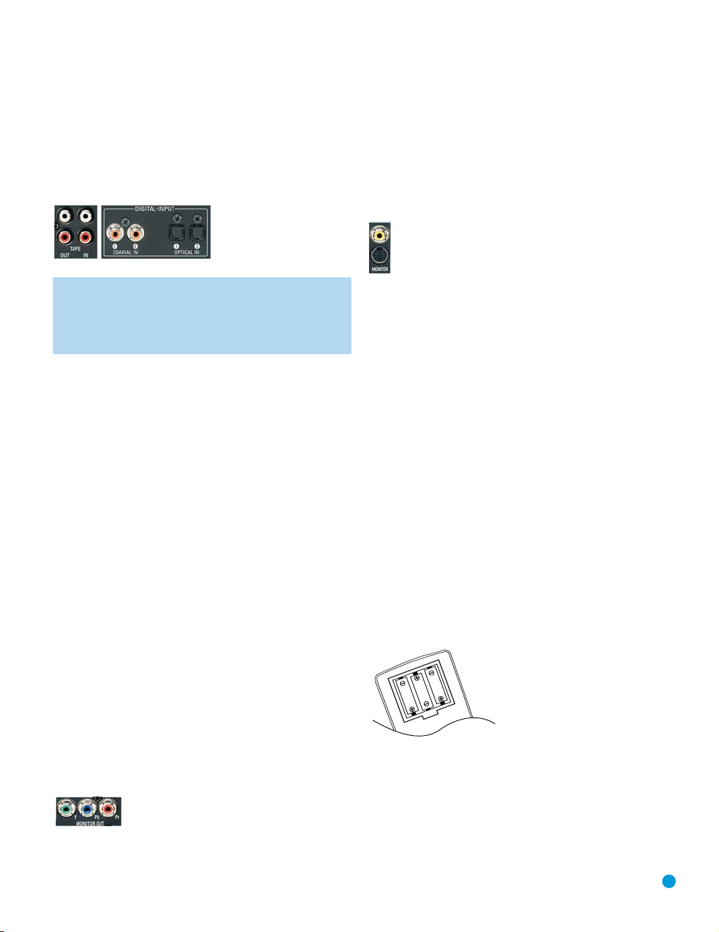
Referring to Table 2, connect your recorder to the Tape Analog
Audio inputs and outputs, and to any available digital audio input.
See Figure 23.
Figure 23 – Tape Audio Inputs and Outputs, and Digital Audio Inputs
NOTE: You will not be able to make digital audio recordings using
the AVR 144. Make sure your source is connected to any of
the AVR 144’s analog audio inputs, and connect your recorder
to either the Video 1 or Tape Analog Audio Outputs. The AVR 144
will not convert a digital audio input signal to analog.
output
Remember to connect the
or digital audio
recorder to the Tape
No video connections are made.
input
jacks on the AVR, and the
output
jacks on your recorder to the Tape
jacks on the AVR.
input
jacks on your
Step Five – Connect Video Display
Only video connections should be made between the receiver and your
video display (TV), unless your TV is the source for your television programming (see note above).
You will need to make a video connection for each type of video used
for your sources. In addition, even if you didn’t use S-video or composite video for any of your sources, you will still need to use one of these
two video monitor connections in order to view the AVR 144’s onscreen menus and displays.
First, determine what types of video your display is capable of handling.
Remember that component video is preferred, followed by S-video and
then composite video. Ideally, this guided you in selecting the video connections for your sources.
Next, note which types of video connections you used for your source
devices. Make sure you didn’t use a better type of video connection for
a source than your video display can handle. If so, you will need to disconnect the source and use a video connection that’s compatible with
your display.
If you used component video for any sources, connect the Component
Video Monitor outputs on the receiver to one set of component video
inputs on your display. Make a note of how these inputs are labeled on
the display. See Figure 24.
Figure 24 – Component Video Monitor Outputs
If you used S-video for any sources, or if all of your sources used component video, connect the S-video Monitor output on the receiver to an
S-video input on your display. Make a note of how the input is labeled.
See Figure 25.
If you used composite video for any sources, connect the composite
video Monitor output on the receiver to a composite video input on the
display. Again, make a note of how this input is labeled on the display.
See Figure 25.
Figure 25 – S-Video and Composite Video Monitor Outputs
Consult the manual for your TV to make sure you understand how to
select each video input. As you play different source devices that use
different types of video connections, you will need to remember to
select the correct video input on your video display.
Step Six – Plug in AC Power
Having made all of your wiring connections, it is now time to plug each
component’s AC power cord into a working outlet.
Before plugging the AVR 144’s AC Power Cord into an electrical outlet,
make sure that the Master Power Switch on the front panel is popped
out so that the word OFF appears on its top. Gently press the button to
turn the switch off. This will prevent the possibility of damaging the AVR
in case of a transient power surge.
Step Seven – Insert Batteries in Remote
The AVR 144 remote control uses three AAA batteries, which are
included.
To remove the battery cover located on the back of the remote, firmly
press the ridged depression and slide the cover towards the top of
the remote.
Insert the batteries as shown in the diagram, making sure to observe
the correct polarity. See Figure 26.
Figure 26 – Remote Battery Compartment
When using the remote, remember to point the lens toward the front
panel of the AVR 144. Make sure no objects, such as furniture, are
blocking the remote’s path to the receiver. Bright lights, fluorescent lights
and plasma video displays may interfere with the remote’s functioning.
The remote has a range of about 20 feet, depending on the lighting
conditions. It may be used at an angle of up to 30 degrees to either
side of the AVR.
23
Page 24
INSTALLATION
If the remote seems to operate intermittently, or if pressing a button
on the remote does not cause the AVR Selector or one of the Input
Selectors to light up, then make sure the batteries have been inserted
correctly, or replace all three batteries with fresh ones.
Step Eight – Program Sources Into the Remote
The AVR 144 remote is capable of controlling not only the receiver,
but it may also be programmed to control many brands and models of
VCRs, DVD players, CD players, cable boxes, satellite receivers, cassette
decks and TVs.
It may help to think of the remote as a book with pages. Each page represents the button functions for a different device. In order to access the
functions for a particular device, you first need to turn to that page. This
is done by pressing the AVR Button to access the codes that control the
receiver, or the Input Selector buttons to access the codes for the
devices programmed into the remote.
At the factory, the AVR 144’s codes and the codes to control many
Harman Kardon DVD and CD players are preprogrammed. If you have
other source devices in your system, follow these steps to program the
correct codes into the remote.
1. Using the codes in Tables A9–A15 of the Appendix, look up the
product type (e.g., DVD, cable TV box) and the brand name of your
source. The number(s) listed are potential candidates for the correct
code set for your particular device.
2. Turn on your source device.
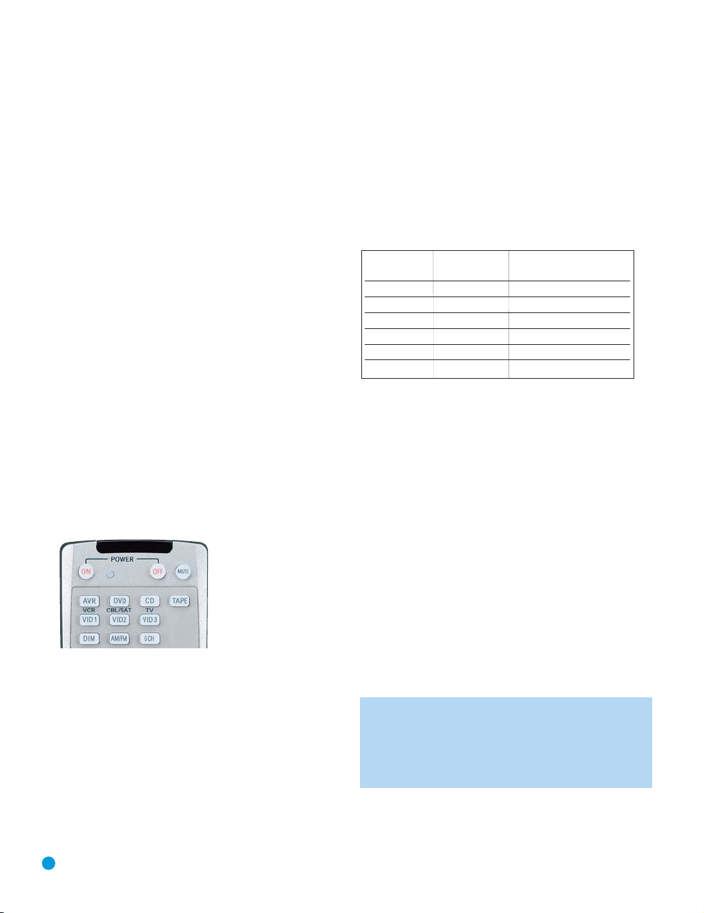
3. Put the remote into Program mode by pressing and holding the Input
Selector and the Mute button simultaneously until the LED on the
remote starts to flash, and then releasing the buttons. See Figure 27.
Figure 27 – Input Selectors
4. Enter a code from Step 1 above.
a) If the device turns off, then press the Input Selector again to accept
the code, which will flash. The remote will exit the Program mode.
b) If the device does not turn off, try entering another code. If you
run out of codes, you may search through all of the codes in the
remote’s library for that product type by pressing the
button repeatedly until the device turns off. When the device turns
off, enter the code by pressing the Input Selector, which will flash.
The remote then exits Program mode.
5. Once you have accepted a code, it’s a good idea to try using some
other functions to control the device. Sometimes manufacturers
⁄ or ¤
use the same Power code for several different models, while other
codes will vary. You may wish to repeat this process until you’ve programmed a satisfactory code set that operates most of the functions
you frequently use.
6. You may find out which code number you have programmed by
pressing and holding the Input Selector and Mute Button simultaneously to enter the Program mode. Then press the Set Button, and the
LED will blink in the code sequence. One blink represents “1”, two
blinks for “2”, and so forth. A series of many fast blinks represents
“0”. Record the codes programmed for each device here.
Source Input Product Type Remote Control Code
(circle one)
Video 1 VCR, PVR
Video 2 Cable, Satellite
Video 3 TV
DVD DVD
CD CD, CDR
Tape Cassette
Table 3 – Remote Control Codes
If you are unable to locate a code set that correctly operates your
source device, it will not be possible to use the AVR remote to control
that device. However, you may still connect the source to the AVR 144
and operate it using the device’s original remote control. Alternatively,
you may wish to consider purchasing Harman Kardon’s optional TC 30
activity-based remote, which is programmed by accessing a large database of product codes on the Internet. The TC 30 is also capable of
“learning” codes from your device’s original remote.
Most of the button labels on the remote describe the button’s function
when used to control the AVR 144. However, the button may perform a
very different function when used to control another device. Refer to the
Remote Control Function List, Table A8 in the Appendix, for a list of
each button’s functions with the various product types.
If you wish, you may program Macros, which are preprogrammed code
sequences that execute many code commands with a single button
press. You may also program “punch-through” codes, which allow the
remote to operate the volume, channel or transport controls of another
device without having to switch the remote to the mode for that device.
See pages 42 – 43 for instructions on these advanced programming
functions.
NOTE: The AVR 144 remote is preprogrammed to operate the
transport controls of Harman Kardon DVD players when the AVR
or the Video 2 (cable/satellite) or Video 3 (TV) source is selected.
The volume and mute controls operate the AVR when any
device except Tape has been selected. You may change this
punch-through programming at any time.
24
Page 25
Step Nine – Turn On the AVR 144
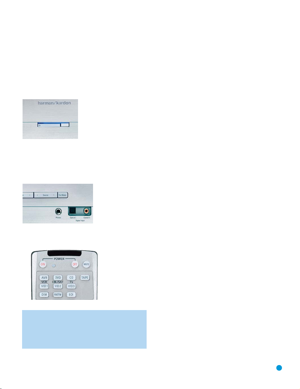
Two steps are required the first time you turn on the AVR 144.
1. Gently press the Master Power Switch until the word OFF is no longer
visible. The Power Indicator above the two power switches should
light up in amber, indicating that the AVR is in Standby mode and is
ready to be turned on. See Figure 28. Normally, you may leave the
Master Power Switch in the ON position, even when the receiver is
not being used.
Figure 28 – Power Switches
2. There are several ways in which the AVR 144 may be turned on from
Standby mode.
a) Press the Standby/On Switch on the front panel. See Figure 28.
b) Press the Source Select Button on the front panel. See Figure 29.
INSTALLATION
Figure 29 – Source Select Button
c) Using the remote, press any one of these buttons: AVR, DVD, CD,
TAPE, VID1, VID2, VID3, AM/FM or 6CH. See Figure 30.
Figure 30 – AVR and Input Selectors
NOTE: Any time you press one of the Input Selectors on the
remote (i.e., DVD, CD, TAPE, VID1, VID2 or VID3), the remote
will switch modes so that it will only transmit the codes programmed to operate that device. In order to control the receiver,
you will need to press the AVR Button to return the remote to
AVR mode.
You are now ready for Initial Setup, in which you will make a few adjustments to ensure that your new AVR 144 receiver performs at its best.
25
Page 26
INITIAL SETUP
Before you begin enjoying your new receiver, a few adjustments should
be made to configure the AVR 144 to match your actual system.
Make sure that you have connected a video display to either the Svideo or composite video monitor output on the receiver. When you turn
on your display and the AVR, you should see a blue screen. A message
may appear briefly at the bottom of the screen. This message is part of
the on-screen display system, and is referred to as the “semi-OSD”. The
semi-OSD is activated any time you send a command to the AVR, and
any time the AVR detects a change in the incoming signal. Semi-OSD
messages are overlaid on top of any video signal, so that you may continue to watch your program while making adjustments to the AVR.
Although it’s possible to configure the AVR using only the remote and
the semi-OSD messages, we recommend that you use the full-screen
menu system, known as the “full OSD”.
Using the On-Screen Menu System
The full OSD system is accessed by pressing the OSD Button on the
remote. While the full OSD system is in use, it isn’t possible to see any
video programming. In addition, an OSD ON message will appear on the
front panel of the receiver to remind you to use a video display.
Figure 32 – Master Menu Screen
If you are an experienced home theater user, you may prefer to use the
menus in this order:
1. System Setup (described in Advanced Functions section)
2. Manual Setup (described here and in Advanced Functions)
3. Input Setup (described in this section)
4. Surround Select (see Advanced Functions section)
However, we recommend that most users follow the instructions in this
INITIAL SETUP section to configure a basic home theater system. You
may return to these menus at any time to make additional adjustments.
This section requires that you complete all of the steps in the Installation
section that apply to your receiver. You should have connected all of
your loudspeakers and a video display, as well as your source devices.
You should be able to turn on the receiver and view a blue screen on
your video display. If necessary, reread the Installation Section before
continuing.
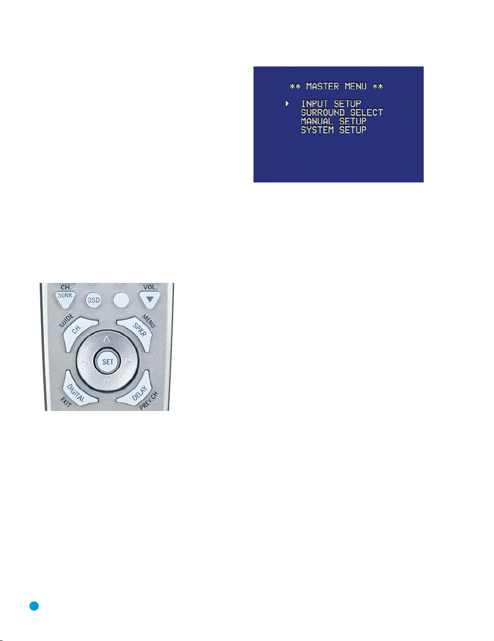
Figure 31 – Navigation Buttons
The Master Menu will always be displayed when you first press the OSD
Button. Use the
ferent lines in the menu. Press the Set Button on the remote to select a
line that has no setting to be adjusted, such as one of the submenus
listed in the Master Menu, or a line that returns you to a previous menu.
Within the submenus, after you have positioned the cursor at a particular
line item, you will need to use the
change a setting. See Figure 31. When the desired setting appears, use
⁄⁄¤
the
setting in the INPUT SETUP menu, there is no need to press the Set
Button after your desired setting appears.
The Master Menu allows access to four submenus: Input Setup,
Surround Select, Manual Setup and System Setup. See Figure 32.
26
⁄⁄¤
Buttons on the remote to point the cursor to dif-
‹/› Buttons on the remote to
Buttons to navigate to another line item. Except for the TITLE
Step One – Determine Speaker Size
The AVR 144 can’t detect how many speakers you’ve connected to it;
nor can it determine their capabilities. For this part of the system setup,
you will need to consult the owner’s guide for each of your speakers. If
you don’t have the guide, you may be able to obtain the speaker’s technical specifications from the manufacturer’s Web site, or by contacting
the manufacturer directly.
The specification you’re looking for is the frequency response, which is
usually given as a range, e.g., 100Hz – 20kHz (±3dB). This specification tells you whether the speaker is able to play sounds that are very
high- or low-pitched, represented by the high and low frequencies. We
are concerned with the lowest frequency that each of your main speakers is capable of playing, which is 100Hz in this example, a respectable
figure for a typical satellite speaker. Use the worksheets in the appendix
to note this number as the crossover for that speaker (not the same as
the crossover frequency listed in the speaker’s specifications).
Page 27
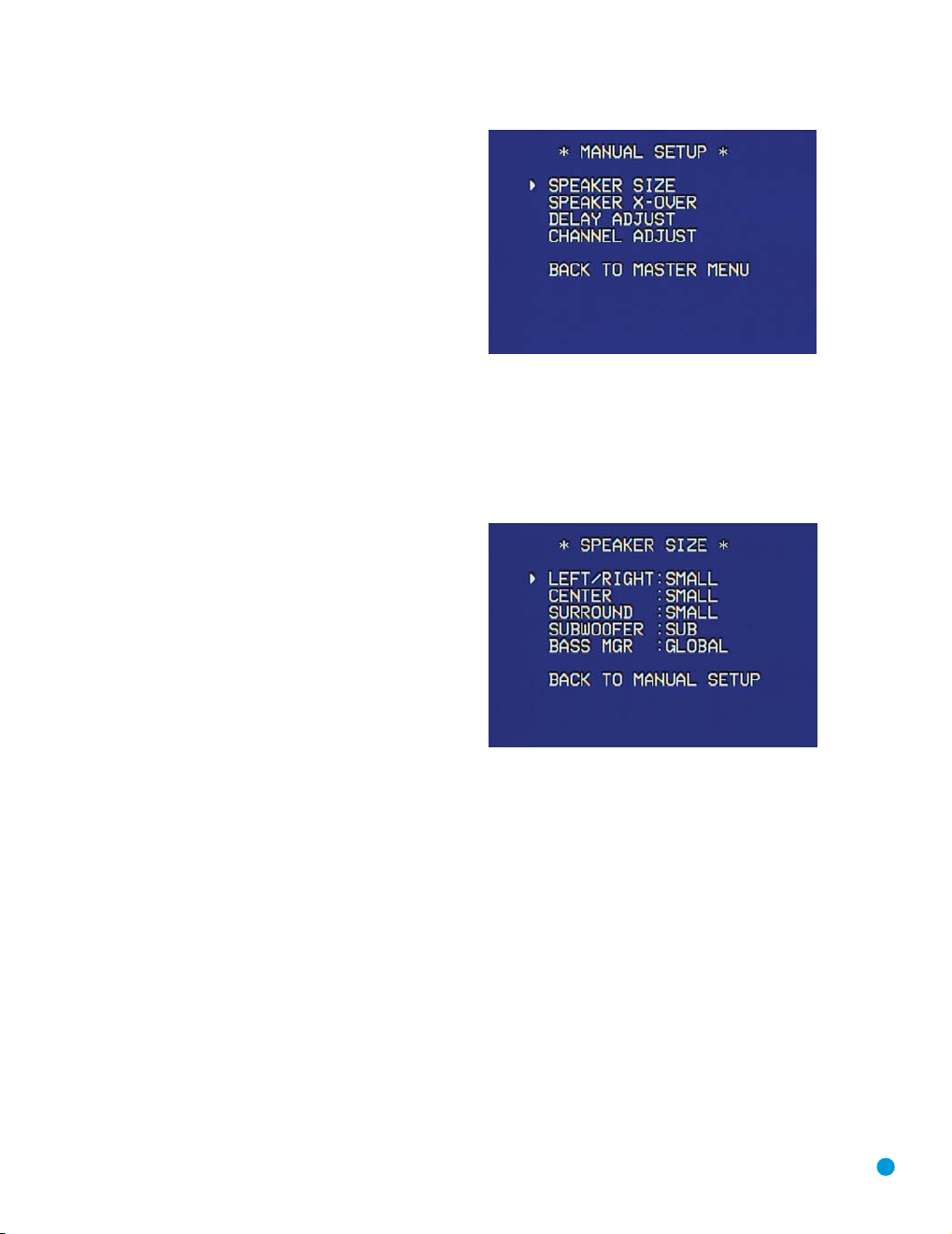
The frequency response for your subwoofer will usually cover only
the very lowest frequencies, since the subwoofer is only designed to
play bass materials. A typical frequency response for a subwoofer is
25Hz – 150Hz. In this case, the higher number is most important
and should be noted in the worksheet.
The purpose of programming this information into the AVR 144 is to
program the receiver’s bass management, which determines which
speakers the receiver will use to play back the low-frequency (bass)
portion of the source program.
If you send the lowest notes to small satellite speakers, you won’t hear
these notes very well, and you may even damage the speaker by going
beyond its capabilities. If you send the highest notes to the special-purpose subwoofer, you may not hear them at all.
With proper bass management, the AVR 144 divides the source signal
at a crossover point. All information above the crossover point is played
through the satellite speaker (front left/right, center or surround
left/right), and all information below the crossover point is played
through the subwoofer. This enables each loudspeaker in your system
to perform at its best, delivering an enjoyable sound experience.
Step Two – Measure Speaker Distances
Ideally, all of your speakers were placed in a circle, each at the same
distance from the listening position. However, your room may not be
ideal, and you may have had to place some speakers a little further
away than others. This could affect the overall sound of the receiver,
as sounds that are supposed to arrive simultaneously from different
speakers blur, due to different arrival times.
Fortunately, the AVR 144 has a delay adjustment that enables the
receiver to compensate for real-world speaker placements.
Before you begin making adjustments, measure the distance from each
speaker to the listening position, and note it in the worksheets in the
appendix. Even if all of your speakers are the same distance from the
listening position, you should enter your speaker distances.
Step Three – Manual Setup Menu
Now you are ready to program these adjustments into the receiver. It’s
best to sit in the usual listening position and make the room as quiet as
possible. Don’t worry if you make a mistake; you can always go back
and change these settings.
With the receiver and video display turned on, press the OSD Button on
the remote. Use the
MANUAL SETUP line, and press the Set Button to display the Manual
Setup menu. See Figure 33.
¤ Button on the remote to move the cursor to the
INITIAL SETUP
Figure 33 – Manual Setup Menu Screen
The Manual Setup menu is the gateway to four submenus:
Speaker Size, Speaker X-Over, Delay Adjust and Channel Adjust.
Speaker Size Menu
Press the Set Button to display the Speaker Size submenu.
See Figure 34.
Figure 34 – Speaker Size Menu Screen
The Speaker Size menu lists each of the speaker groups. You will be
programming the correct setting for each group, indicating how many
speakers are in your system and what their capabilities are, based on
the information you obtained in Step One – Determine Speaker Size.
Each of the main speaker groups can be set to one of three settings:
LARGE, SMALL or NONE. These settings don’t refer to the physical size
of the speaker, but rather to the size of the frequency range of each
speaker. These may or may not turn out to be the same.
If the lower number of the frequency response for your speakers is less
than 100Hz, choose the LARGE setting. If this number is 100Hz or
greater, choose the SMALL setting. If you don’t have a speaker connected to that position, choose NONE.
As you can see, the system requires you to use both speakers in a pair.
For example, you can’t connect just a front left speaker without a right
speaker, or just a right surround (rear) speaker without a left one.
However, you can connect only the front speakers, or both front and
surround speakers without a center, or the front left/right and center
speakers without any surrounds.
27
Page 28
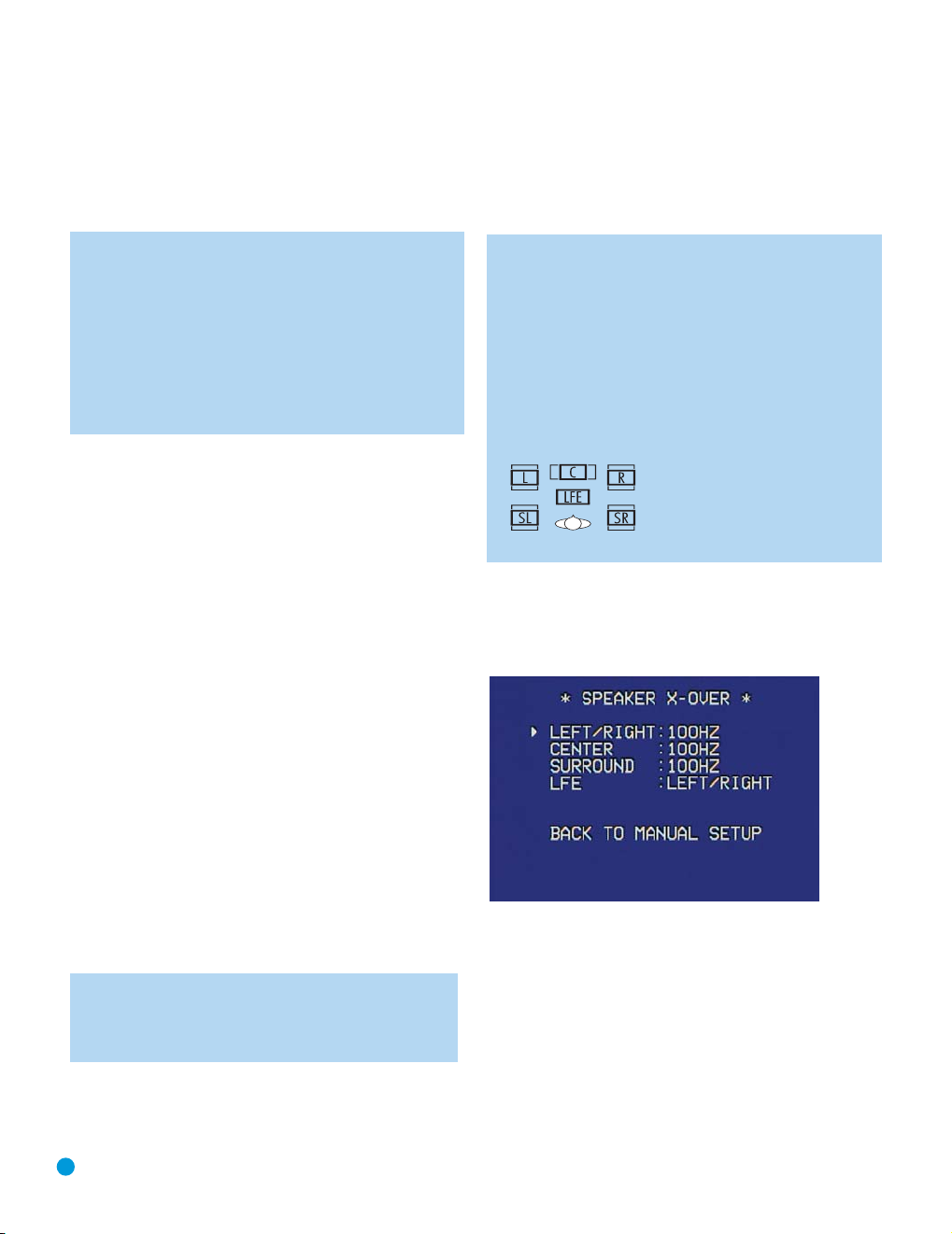
INITIAL SETUP
LEFT/RIGHT: This line tells the AVR 144 the capabilities of your front
left and right speakers. Use the ‹/› Buttons to select either SMALL
or LARGE for these speakers.
CENTER: Move the cursor to the line for the center speaker, and use
the ‹/› Buttons to select a setting for this speaker.
NOTE: If the receiver is currently in one of the Logic 7 surround
modes, which will be the case the first time you turn on the
receiver, you won’t be able to set the center speaker to LARGE,
due to the requirements of the Logic 7 processor. You may use
the SMALL setting instead. As you listen to the receiver, if you
find the SMALL setting is not satisfactory, change the surround
mode to one of the Dolby Pro Logic II modes (using the
Surround Select menu, accessible from the Master Menu), and
then you may come back to this menu and change the center
speaker to the LARGE setting.
SURROUND: Move the cursor to the line for the surround, or rear,
speakers, and use the ‹/› Buttons to select a setting for these
two speakers.
SUBWOOFER: Move the cursor to the line for the subwoofer, which is
programmed a little differently. The subwoofer’s “size” setting depends
upon how you programmed the front left and right speakers.
• If you set the front speakers to SMALL, the subwoofer setting will
be SUB, and you won’t be able to change it. All low-frequency
information will always be sent to the subwoofer. If you don’t have
a subwoofer, you may wish to set your front speakers to LARGE
so as not to lose this information, but you may need to lower the
volume to avoid adverse results.
• If you set the front speakers to LARGE, you may select from three
possible settings for the subwoofer.
L/R+LFE: This setting sends all low-frequency information to the
•
subwoofer, including both information that would normally be
played through the front left and right speakers and the special
low-frequency effects (LFE) channel information.
• LFE: This setting plays low-frequency information contained in
the left and right program channels to the front speakers, and
directs only the LFE channel information to the subwoofer.
• NONE: This setting steers all low-frequency information to the
front speakers, and no information to the subwoofer output. Use
this setting if you have a passive subwoofer, or a powered subwoofer that you connected to the front speaker outputs.
NOTE: If you are using a Harman Kardon HKTS speaker system, select the SMALL setting for the LEFT/RIGHT, CENTER
and SURROUND lines, and the subwoofer will automatically be
set to SUB.
BASS MGR: This advanced setting is used if you wish to configure your
speakers differently for different sources. For example, you may prefer to
set your speakers to LARGE while listening to CDs from your CD player.
By changing this setting to INDEPENDENT, you may have different set-
tings for your CD player and your DVD player or other devices. We recommend that you leave this setting at its factory default of GLOBAL until
you have more experience with the AVR.
Move the cursor to the BACK TO MANUAL SETUP line and press the
Set Button to return to the Manual Setup Menu.
NOTE: The Speaker/Channel Indicators on the front panel of
the receiver will display the speaker size settings as follows. For
each speaker configured as SMALL, a single box will appear in
the position for that speaker. For each speaker configured as
LARGE, a double box will appear in its position. If a speaker is
configured as NONE, no box will appear. The subwoofer will be
indicated by a single box, or no box if no subwoofer has been
configured. The letters inside the boxes appear when a digital
signal is being received that has that channel discretely encoded.
The letters flash when the signal is not present, such as when a
DVD is paused.
Figure 35 – Speaker/Channel Input Indicators
Speaker Crossover Menu
On the Manual Setup menu, move the cursor to the SPEAKER X-OVER
line and press the Set Button to display the Speaker Crossover menu.
See Figure 36.
Figure 36 – Speaker Crossover Menu Screen
Setting the Speaker Crossover menu correctly ensures that your speakers
are properly used so that they sound their best. Although you could skip
this step the first time you use the receiver, we recommend that you
take the few extra minutes to enter the correct crossover settings.
You may select from seven possible settings: 40Hz, 60Hz, 80Hz,
100Hz, 120Hz, 150Hz or 200Hz. Depending upon the frequency
response of your speakers which you recorded in Step One –
Determine Speaker Size, for each speaker group select the number
that matches or is just above the low end of your speaker’s frequency
response.
28
Page 29
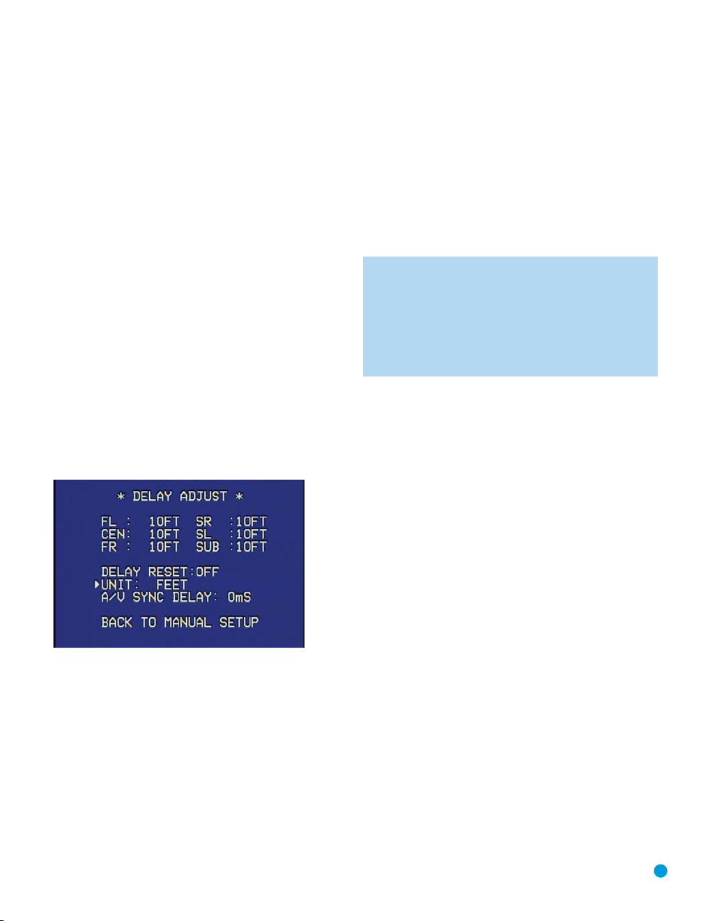
INITIAL SETUP
The LFE line sets the frequency for a low-pass filter that determines
what information is sent to the subwoofer for playback. Since the subwoofer output combines low-frequency information for all channels, in
order to make sure that no information is lost due to different speakers
having different capabilities, the subwoofer filter should be matched to
the highest crossover frequency used for any speaker group.
Looking at each of your three speaker-group settings in this menu,
determine which group is set to the highest frequency. Move the cursor
to the LFE line, and use the
If all three speaker groups have the same setting, you may leave the
LFE filter to its factory default of the LEFT/RIGHT speaker group.
Move the cursor to the BACK TO MANUAL SETUP line and press the
Set Button to return to the Manual Setup menu.
‹/› Buttons to select that speaker group.
Delay Adjust Menu
As explained above in Step Two – Measure Speaker Distances, sometimes the speakers are placed at different distances from the listening
position, which can muddy the sound, as sounds are heard earlier or
later than desired.
Even if all of your speakers are placed the same distance from the
listening position, you should not skip this menu.
On the Manual Setup menu, move the cursor to the DELAY ADJUST
line and press the Set Button to display the Delay Adjust menu.
See Figure 37.
Figure 37 – Delay Adjust Menu Screen
This menu requires you to enter the distance from each speaker to the
listening position, which you measured in Step Two – Measure Speaker
Distances.
The default unit of measurement is in feet. If you wish to change the unit
to meters, move the cursor down to the UNIT line, and use the ‹/›
Buttons to change the unit to METER.
⁄/¤ Buttons to move the cursor to the FL (front left) line;
Use the
then use the ‹/› Buttons to change the measurement as needed.
⁄/¤ Buttons to move to each speaker in turn – CEN
Use the
(center), FR (front right), SR (surround right), SL (surround left) and
SUB (subwoofer).
DELAY RESET: This line is used if you wish to reset all of the speaker
delay settings to the factory default of 10 feet (3.0 meters) at once.
Use the ‹/› Buttons to change the setting of OFF to ON. If you
change any speaker’s setting, this line will automatically revert to OFF.
This will also reset the A/V Sync Delay setting to 0mS.
A/V SYNC DELAY: This line allows you to compensate for a situation in
which one of your source devices, or your video display, introduces a
significant amount of video processing that causes the audio and video
parts of the signal to get out of sync. This is known as a “lip sync” problem. You may delay the audio for all channels by up to 80 milliseconds
to compensate.
NOTE: We recommend that you adjust the A/V Sync Delay
using the Delay Button on the remote, rather than in this menu,
so that you can view the picture while adjusting the audio delay.
With the program playing, press the Delay Button, and the A/V
SYNC DELAY message will appear on the front panel and in the
semi-OSD display. Press the Set Button to display the current
delay setting, and use the
until the synchronization issue is resolved.
Move the cursor to the BACK TO MANUAL SETUP line and press the
Set Button to return to the Manual Setup menu, or simply press the
OSD Button to exit the menu system.
‹/› Buttons to adjust the setting
Step Four – Output Level Calibration
This is an important step in the configuration process, and should not
be skipped.
Many people assume that during a presentation, such as a movie, the
surround channels will sound as loud as the front channels. However,
this is usually not the case, as directors often steer only ambient or
background sounds to the surround channels. For example, during
a rainy scene you may only hear rain falling, with the occasional
thunderclap, from the surround speakers while the main dialogue is
heard from the center speakers. At times, you may not hear any
sounds at all from the surround channels.
In order to achieve these effects successfully, it is important that the
surround channels be calibrated to sound as loud as the other channels
when a test tone is played. Therefore, calibrating the speaker output
levels so that all speakers sound equally loud at the listening position
is a critical step in the setup process.
By now you should have connected all of your speakers and sources
and your video display. You should have turned on the receiver and
used the Manual Setup menus to configure each of your speakers.
Sit in the listening position with the remote control, and make sure to
eliminate external noises for the few minutes needed to calibrate the
output levels.
You may use a handheld SPL meter (available at most electronics stores)
set to the C-Weighting, Slow scale, or you may calibrate the levels by
Try to adjust the levels so that all channels sound equally loud.
ear.
29
Page 30
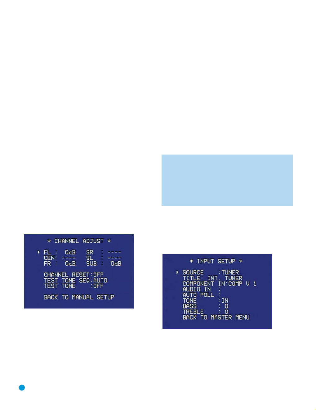
INITIAL SETUP
If you are using a handheld SPL meter with source material, such as a
test disc or another audio selection, play it now and adjust the AVR’s
meter
master volume control until the
measures 75dB.
If you are using the AVR’s internal test tone, then adjust the AVR’s
master volume to –15dB.
Adjust the levels using either the remote control by itself, or using the
full-OSD menu system.
A. Using the Remote Control With the Test Tone
While sitting in the listening position, press the Test Button on the
remote. The test tone will start playing at the front left channel. After
a few seconds, it will move to the center channel, then the front right
channel, surround right, surround left and finally the subwoofer, displaying
the channel name on the front of the receiver and in the semi-OSD display, as well as the current level setting (varies between –10dB and
+10dB). Press the
⁄/¤ Buttons to adjust the level setting, and the
tone will remain at that channel until several seconds after your last
adjustment. When you have finished adjusting the levels, press the Test
Button again to stop the tone. Measure the levels by ear or using an
SPL meter, as described above.
B. Using the Full-OSD Menu
The full-OSD menu system offers the easiest and most flexible manner
of setting output levels. Press the OSD Button to display the Master
Menu, and then navigate to the MANUAL SETUP line. Press the Set
Button to display the Manual Setup menu, and then navigate to the
CHANNEL ADJUST line. Press the Set Button to display the Channel
Adjust menu. See Figure 38.
If you would like to set your levels using the AVR 144’s internal test tone, you
will need to adjust the TEST TONE SEQ and TEST TONE lines as follows.
TEST TONE SEQ: When this setting reads AUTO, the test tone will automatically circulate to all channels, pausing for a few moments at each
channel and then moving to the next channel several seconds later, as
indicated by the blinking cursor. You may adjust the level for any channel
when the test tone is paused there by using the
also use the
⁄/¤ Buttons at any time to move the cursor to another
‹/› Buttons. You may
line, and the test tone will follow the cursor.
When this setting reads MANUAL, the test tone will not move to the
next channel until you use the
⁄/¤ Buttons to move it.
TEST TONE: This line determines whether the test tone is active or not.
To begin the process of setting the levels, use the
‹/› Buttons to
change the setting to ON. Any time you manually move the cursor out of
the channel listings area of the screen, this setting will automatically
change to OFF, ending the test tone.
NOTE: Setting the channel levels while one surround mode is
active does not necessarily carry over to all other modes. We
recommend that after you have set the levels satisfactorily in
one mode, you note the results and change to other surround
modes. For those modes that don’t reflect your level settings,
you may either copy the settings you obtained as a short cut, or
redo the procedure to determine the correct settings for those
surround modes.
Step Five – Configure Sources
This is the last step in the configuration process.
Press the OSD Button to view the Master Menu. The cursor will be
pointing to the INPUT SETUP line, and you need only press the Set
Button to display the Input Setup menu. See Figure 39.
Figure 38 – Channel Adjust Menu Screen
All of the speaker channels will appear at the top of the screen with their
current level settings. Any channels that have not been programmed using
the Speaker Size menu will display four dashes and will not be accessible.
CHANNEL RESET: If you wish to start by resetting all of the levels to
their factory defaults of 0dB, navigate to this line and change the setting
to ON. The levels will be reset, and this setting will then revert to OFF.
If you are using an external source to set your output levels, simply navigate
to each channel and use the
30
⁄/¤ Buttons to adjust the level as desired.
Figure 39 – Input Setup Menu Screen
The first line indicates that the receiver is currently set to the tuner
source. In fact, you may hear static if the tuner is set to an unused frequency. You will not be able to make any changes to the tuner, other
than selecting a component video input or adjusting the tone controls.
It is not recommended that you make either of these changes for
the tuner.
Page 31
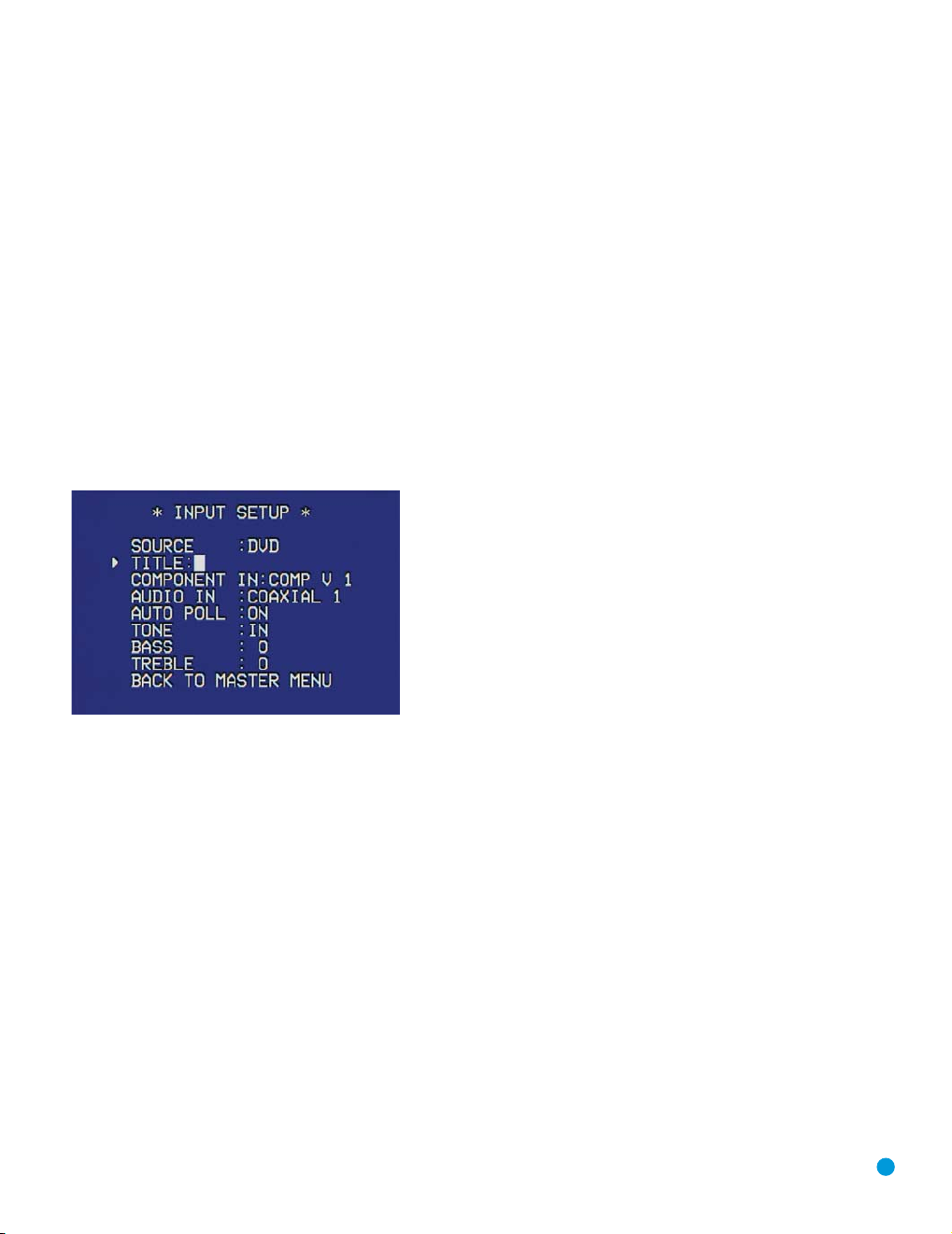
INITIAL SETUP
Press the ‹Button to view the next source. The sources will be selected
in the following order: Tape, 6-Channel Inputs, Video 1, Video 2,Video 3,
DVD and CD. Pressing the
› Button selects the sources in the reverse order.
For each of these sources, you may adjust the settings below. At a minimum, you should make sure that sources you connected to either of
the component video inputs have the correct settings, and that sources
you connected to any of the digital audio inputs also display the correct
settings. Other settings are optional, and you may adjust them at a
later time when you have more experience with the AVR. Refer to the
worksheets you filled out during installation as you assign inputs to
each source.
TITLE: You may change the display name for any source (except the
tuner). Not only does this enable you to customize your system; it helps
you to select the correct source device even when you have forgotten
which physical connections you used.
Move the cursor down to the TITLE line and press the Set Button.
A block cursor will blink. See Figure 40.
AUTO POLL: The Auto Poll feature is used when both an analog audio
and digital audio connection have been made for one source device.
If for some reason no digital signal is available, the AVR 144 will switch
to the analog inputs for the source. This situation can occur with some
cable or satellite television broadcasts, where some channels are broadcast with digital audio and others with analog audio.
For some sources, the Auto Poll feature is unnecessary and may be
undesirable. For example, if your DVD player is stopped, you may not
want to use the analog audio signal or you may have decided not to
connect analog audio. Move the cursor to this line, and press the
‹/›
Buttons until OFF appears, disabling the Auto Poll feature. With Auto Poll
turned off, the receiver will only check for a signal at the audio input
assigned to the source.
The remaining lines in the Input Setup menu activate the tone controls,
and may be skipped at this time. We recommend leaving the tone
controls at their factory defaults for most listening, in order to enjoy the
sound mix created by your favorite movie and music artists. However,
if your room or speakers have unusual characteristics, or simply as a
matter of personal preference, see the Tone Controls section on
page 33 for more information.
You are now ready to begin enjoying your new receiver!
Figure 40 – Retitling a Source Input
Now you may use the ⁄/¤ Buttons to scroll through the alphabet in
upper and lower case, as well as numbers and a variety of punctuation
marks. When you have selected the desired character, press the ›
Button to move to the next space. You may also press the › Button to
leave a blank. Press the Set Button when you have finished spelling out
the new display name for the source.
COMPONENT IN: If you connected the source to one of the two component video inputs, make sure the correct set of inputs is displayed at this
line. If it isn’t, move the cursor to this line, and then press the
change the setting.
› Button to
AUDIO IN: By default, the analog audio inputs are assigned to all
sources at the factory other than the DVD and Video 2 sources, which
default to Coax 1 and Optical 1, respectively. If you used a digital audio
connection for the source, you will need to change this setting to assign
the correct digital audio input to the source, even if you also connected
the analog audio outputs of the source to the receiver. Move the cursor
to this line, and press the
‹/› Buttons until the correct digital input
appears.
31
Page 32
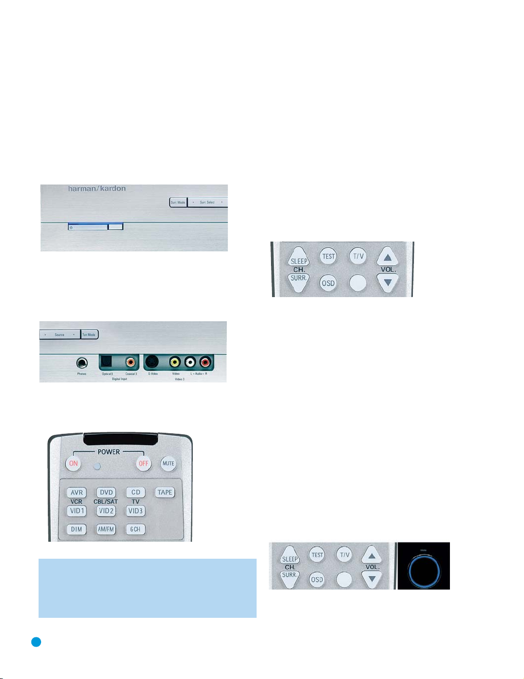
OPERATION
Now that you have installed your system components and completed at
least a basic configuration of your receiver, you are ready to begin
enjoying your home theater system.
Turning On the AVR 144
Gently press the Master Power Switch until the word OFF is no longer visible. The Power Indicator above the two power switches should light up in
amber. This indicates that the AVR is in Standby mode and is ready to be
turned on. Normally, you may leave the Master Power Switch in the ON
position, even when the receiver is not being used. See Figure 41.
Figure 41 – Power Switches
There are several ways in which the AVR 144 may be turned on:
a) Press the Standby/On Switch on the front panel. See Figure 41.
b) Press the Source Select Button on the front panel. See Figure 42.
Figure 42 – Source Select Button
c) Using the remote, press any one of these buttons: AVR, DVD, CD,
TAPE, VID1, VID2, VID3, AM/FM or 6CH. See Figure 43.
To turn the receiver off, press either the Standby/On Switch on the front
panel, or press the AVR Button and the OFF Button on the remote.
Unless the receiver will not be used for an extended period of time
(for example, if you will be on vacation), it is not necessary to turn off
the Master Power Switch. When the Master Power Switch is turned off,
any settings you have programmed, including system configuration and
preset radio stations, will be preserved for up to four weeks.
Sleep Timer
You may program the AVR to play for up to 90 minutes and then turn
off automatically using the sleep timer.
Press the Sleep Button on the remote, and the time until turn-off will be
displayed. Each additional press of the Sleep Button will reduce the time
until turn-off by 10 minutes, until the OFF setting is reached, which disables the sleep timer. See Figure 44.
Figure 44 – Sleep Button
When the sleep timer has been set, the front-panel display will automatically dim to half-brightness. If you press any button on the remote or
front panel, the display will return to full-brightness. The display will dim
again several seconds after your last command.
If you press the Sleep Button after the timer has been set, the remaining
time until turn-off will be displayed. You may press the Sleep Button to
change the time until turn-off. Pressing and holding the Sleep Button will
disable the sleep timer, and the SLEEP OFF message will appear.
Volume Control
The volume may be adjusted either by turning the knob on the front
panel (clockwise to increase volume or counterclockwise to decrease
volume), or by pressing the Volume Control Buttons on the remote. See
Figure 45. The volume is displayed as a negative number of decibels
(dB) below the 0dB reference point, and may be changed in 0.5dB
increments. Unlike some volume controls on other products, 0dB is the
maximum volume for the AVR 144. Although it’s physically possible to
turn the volume to a higher level, doing so may damage your hearing
and your speakers. For certain more dynamic audio materials, even 0dB
may be too high, allowing for damage to equipment.
Figure 43 – AVR and Input Selectors
NOTE: Any time you press one of the remote’s Input Selectors
(i.e., DVD, CD, TAPE, VID1, VID2 or VID3), the remote will switch
modes so that it will only transmit the codes programmed to
operate that device. In order to control the receiver, you will need
to press the AVR Button to return the remote to AVR mode.
32
Figure 45 – Volume Controls
Page 33
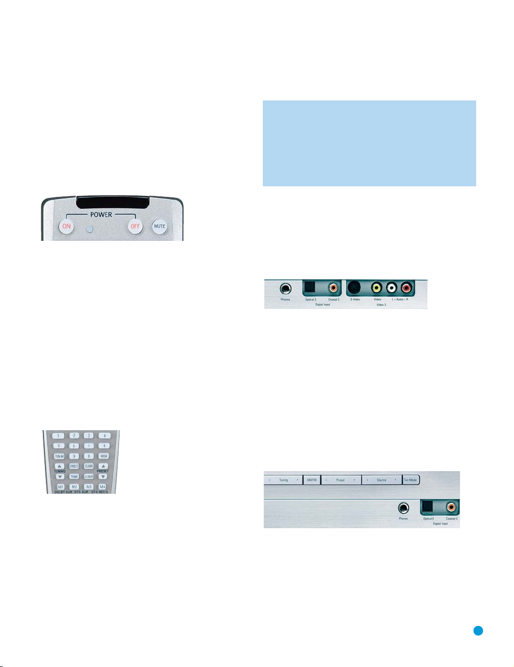
OPERATION
Remember that the AVR 144 is designed to reproduce audio with a
minimum amount of distortion. This clarity may lead you to believe that
your hearing and the equipment can handle higher volumes. We urge
caution with regard to volume levels.
Mute Function
To temporarily mute all speakers and the headphones, press the Mute
Button on the remote. See Figure 46. Any recording in progress will not
be affected. The MUTE message will flash in the display as a reminder.
To restore normal audio, either press the Mute Button again, or adjust
the volume. Turning off the AVR will also end muting.
Figure 46 – Mute Button
Tone Controls
You may boost or cut either the treble or the bass frequencies by up
to 10dB in 2dB increments.
Using the remote, press the Tone Mode Button once. See Figure 47.
This will indicate whether the tone controls are in or out of the circuitry.
If you wish to return the tone controls to 0, or “flat” response, press the
⁄/¤ Buttons until the TONE OUT message appears, which preserves
any changes you have made to the bass or treble settings for later use.
To reactivate your changes, the tone control must again be set to
TONE IN.
With the TONE IN message displayed, press the Tone Mode Button
repeatedly to access TREBLE MODE and BASS MODE. Use the
⁄/¤ Buttons to change the treble or bass settings, as desired. The
display will return to normal a few seconds after your last command.
press the OSD Button to clear the display, or move the cursor to the
BACK TO MASTER MENU line if you wish to make other changes using
the menu system.
NOTE: The AVR 144 does not have any conventional balance
control. The output level calibration process compensates for any
characteristics of your room or speakers, and we recommend
that you leave the settings as they are after the speakers have
been calibrated. However, you may manually adjust the levels of
the left and right channels – decreasing one and increasing the
other by the same amount – using the Channel Adjust submenu.
This achieves the same effect as a balance control.
Headphones
Plug the 1/4" plug on a pair of headphones into the headphone jack
on the front of the receiver for private listening. See Figure 48. The
first time you use the headphones, the DOLBY H:BP message will be
displayed, indicating that Dolby Headphone surround processing is in
the bypass mode, which delivers a conventional 2-channel signal to
the headphones.
Figure 48 – Headphone Jack
Press the Surround Select Button on the front panel, or the Dolby
Button on the remote, to switch to Dolby Headphone virtual surround
processing, indicated by the DOLBY H:DH message. Dolby Headphone
delivers an enhanced sound field that emulates a 5.1-channel speaker
system. No other surround modes are available for the headphones.
Source Selection
Press the front-panel Source Select Button to scroll through the
sources. The left side of the button scrolls down the list that appears in
the display; the right side scrolls upward. For direct access to the tuner,
press the Tuner Band Button, which switches to the last-used band and
frequency. See Figure 49. For direct access to any source, press its
Input Selector on the remote (see Figure 43).
Figure 47 – Tone Button
You may alternatively adjust the tone controls using the full-OSD menu
system. Press the OSD Button on the remote to view the Master Menu.
The cursor will be pointing to the INPUT SETUP line; press the Set
Button to display that menu. You will be able to view the tone settings. If
you wish to make any changes to the TONE, BASS or TREBLE settings,
use the arrow keys on the remote to move the cursor to the line you
wish to change. Once you have changed the setting using the
Buttons, simply move the cursor up or down to a different line; it isn’t
necessary to press the Set Button to enter the new setting. When you
have finished, either wait until the display times out and disappears,
‹/›
Figure 49 – Source Select and Tuner Band Buttons
The AVR 144 will switch to the audio and video inputs assigned to that
source. If you set the BASS MGR setting in the Speaker X-Over menu
to INDEPENDENT, the AVR 144 will change the speaker size configuration to the one you programmed for the source. If you selected a surround mode for the source, the AVR 144 will switch to that mode.
33
Page 34
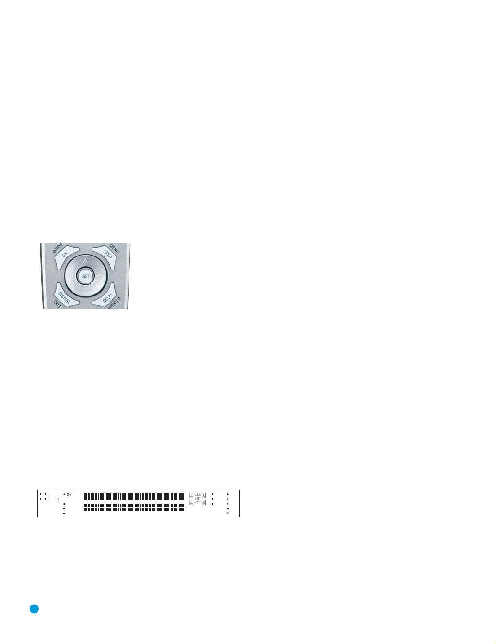
OPERATION
The source name will appear in the upper line of the front-panel display.
If you retitled the source, only the new title will appear. Otherwise, the
audio input assigned to the source (analog or one of the digital audio
inputs) will also appear. The surround mode will be displayed on the
lower line. The same information will also appear on screen in the
semi-OSD, unless you have set the semi-OSD to OFF in the System
Setup menu (see Advanced Functions section).
Audio Input Selection
The AVR 144 is programmed at the factory to use the analog audio
inputs for each source (except for the DVD and Video 2 sources, which
default to Coax 1 and Optical 1). To assign a digital audio input to a
source (if you have not done so using the Input Setup menu during
Initial Setup), press the Digital Button on the remote. The current audio
input selection will flash in the display, and you may press the
⁄/¤
Buttons to scroll through the audio inputs. When the desired input
appears, press the Set Button to select it. See Figure 50.
Figure 50 – Digital Input Selection
If the Auto Poll feature has been left ON in the Input Setup menu, and if
a digital audio input has been assigned to the source, the AVR 144 will
first check the digital audio input for a signal. If a signal is present, the
AVR 144 will select the digital audio input. If no signal is present, the
AVR 144 will switch to the analog audio inputs for the source.
Video Input Selection
When a source is selected, the AVR 144 switches to a video input
as follows:
The COMPONENT IN line of the Input Setup menu indicates which
of the two component video inputs on the AVR 144 is assigned to
each source. All of the sources listed in the left column of the Source
Indicators display on the front panel are assigned to the Component
Video 2 inputs by default, and the sources listed in the right column
default to the Component Video 1 sources. This list appears in
Figure 51.
DIGITAL LOGIC 7
PRO LOGIC
DSP
5 CH. STEREO
SURR. OFF
Figure 51 – Front-Panel Input Indicators
You may reassign either component video input to another source, but
there is no option to disable the component video inputs for any source.
If a signal is present at the component video input assigned to that
source, it will be selected. If your device is not using component video,
make sure that other devices connected to the component video inputs
are turned off.
VID 1
DVD
CD
VID 2
FMAM
VID 3
TAPE
6 CH
If no signal is present at the component video input, then the S-video or
composite video input for the source will be selected. It is not possible
to reassign the S-video or composite video inputs to other sources.
For audio-only sources, such as the tuner or CD inputs, when no
component video signal is present, the last-used video source will be
selected.
6-Channel Direct Inputs
If you wish to hear audio through the 6-Channel Direct Inputs together
with video, then connect your multichannel player to the Component
Video 1 Inputs, and connect the player’s 6-channel analog audio outputs
to the 6-Channel Inputs on the AVR. Assign the Component Video 1
input to the 6-Channel Input source. The AVR will automatically select
the correct component video and audio inputs when you select this
source.
If you need to use composite or S-video for your multichannel player,
e.g., if your video display does not have component video inputs, then
you will need to use the video inputs for another source. Since the
AVR automatically selects the last-used video inputs for audio sources,
first select the source you connected the video cables to, and then
the 6-Channel Inputs for the audio.
Example: You would like to connect a DVD-Audio player to the AVR 144.
You plan on playing a variety of discs using this player, including conventional DVDs and even CDs as well as multichannel discs. When
playing DVDs and CDs, it is preferable to use a digital audio connection
to obtain the best sound quality and the benefit of any digital surround
formats contained on the DVD. However, when playing DVD-Audio discs,
you will need to use the 6-channel analog audio connections. In addition,
some of these discs contain video materials.
We recommend you connect this player as follows:
a) Connect the player’s coaxial digital audio output to the Coaxial 1 input
on the AVR. This input is assigned by default to the DVD source.
b) Connect the player’s component video outputs to the Component
Video 1 inputs on the AVR, which are assigned by default to the DVD
and 6-Channel Input sources. If your video display doesn’t have component video inputs, then connect the player’s composite or S-video
output to the DVD’s corresponding video input.
c) Connect the player’s 6-channel analog audio outputs to the AVR’s
6-Channel Inputs.
d) Program the player’s remote control codes into the DVD Input
Selector. Note that not all commands will necessarily be available.
When you wish to view a DVD, simply select the DVD source.
When you wish to listen to a DVD-Audio disc and view the menus and
other still images on the disc, first select DVD, and then select the 6-/8Channel Inputs as the source. See Figure 52.
34
Page 35
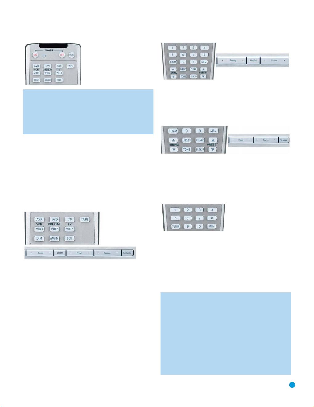
Figure 52 – 6-Channel Input Selector
NOTE: The 6-Channel Inputs pass the incoming signals directly
to the volume control, without digitizing or processing them.
Therefore, you will need to configure bass management settings
(i.e., speaker size, delay and output level) on your source device
so that they match the settings you programmed using the
Manual Setup menu. Consult the owner’s guide for your multichannel player for more information.
Using the Tuner
The AVR 144’s built-in tuner may be selected in one of three ways (see
Figure 53):
1. Press the Source Selector Button on the front panel repeatedly until
the tuner is selected. The last-used band (AM or FM) will be active.
2. Press the Tuner Band Button (marked AM/FM). Press this button
again to switch bands.
3. Press the Tuner Input Selector (marked AM/FM) on the remote. Press
this button again to switch bands.
OPERATION
Figure 54 – Tuning a Station
Press the Tuning Mode Button (TUN-M on the remote) to switch
between Auto and Manual tuning modes. When an FM station has been
tuned, pressing the Tuning Mode Button will switch between stereo and
mono tuning, which may improve reception of weaker stations. See
Figure 55.
Figure 55 – Tuning Mode
To store a station in one of the 30 presets (see Figure 56):
1. Tune the desired station.
2. Press the Memory Button on the remote.
3. Use the Numeric Keys to enter the desired preset number.
Figure 53 – Tuner Input Selection
Radio stations may be selected in one of four ways (see Figure 54):
1. If you know the frequency number, enter it directly by first pressing
the Direct Button on the remote, and then using the Numeric Keys.
2. After you have programmed Preset stations (see below), either enter
the Preset number (1 through 30) using the remote or use the frontpanel Preset Stations Button to scroll through the list of presets.
3. In Auto tuning mode, with each press of the Tuning Buttons (frontpanel or remote) the AVR 144 will scan in the chosen direction until a
station with acceptable signal strength is detected. Press the Tuning
Button again to stop scanning.
4. In Manual tuning mode, with each press of the Tuning Buttons the
AVR 144 will tune the next frequency increment (0.1MHz for FM, or
10kHz for AM) in the selected direction. Press and hold the Tuning
Button for faster scanning.
Figure 56 – Storing a Preset Station
Recording
Two-channel analog audio signals, as well as composite and S-video
signals, are normally available at the appropriate recording outputs. Thus,
to make a recording, you need only make sure to connect your audio or
video recorder to the appropriate output jacks, as described in the
Installation section, insert blank media and make sure the recorder is
turned on and recording while the source is playing.
NOTES:
1. Analog audio signals are not converted to digital form, and
digital audio signals are not converted to analog audio form.
2. The AVR 144 is not designed to make digital audio recordings. Make sure your source device is connected to one of
the AVR 144’s analog audio inputs, and connect your
recorder to either the Video 1 or Tape analog audio outputs.
3. Component video sources are not available for recording.
4. Please make certain that you are aware of any copyright
restrictions on any material you record. Unauthorized duplication
of copyrighted materials is prohibited by federal law.
35
Page 36
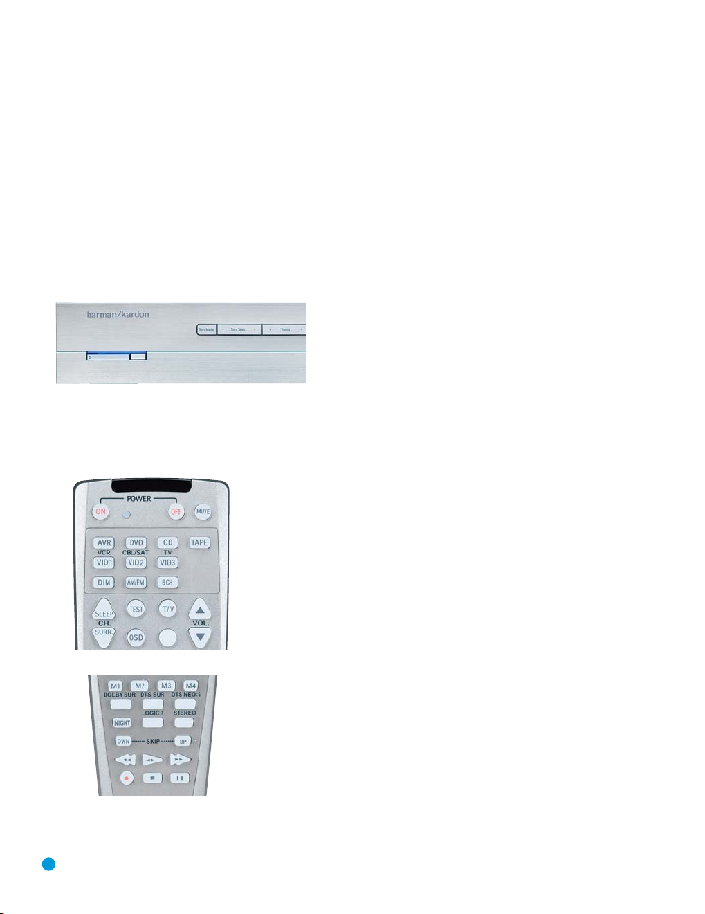
OPERATION
Selecting a Surround Mode
Surround mode selection can be as simple or sophisticated as your
individual system and tastes. Feel free to experiment with the many
available surround modes on the AVR 144, and you may find a few that
become your favorites for certain sources or program types. Although
more detailed information on surround modes may be found in the
Advanced Functions section, it is easy to select any of the modes
available at a given time:
To select a surround mode using the front-panel controls, press the
Surround Mode Button repeatedly until the desired group of modes is
selected: Logic 7, Dolby, DTS, DSP or Stereo. Then press the Surround
Select Button repeatedly to select the desired mode within the group.
See Figure 57.
Figure 57 – Select a Surround Mode (Front Panel)
To select a surround mode using the remote control, locate the button
dedicated to the desired group of modes: Logic 7, Dolby Sur, DTS Sur,
DTS Neo:6, Surr (DSP) or Stereo. Press that button repeatedly to select
the desired mode. See Figure 58.
To select a surround mode using the full-OSD menu system, press the
OSD Button to display the Master Menu. Navigate to the SURROUND
SELECT line and press the Set Button to view the Surround Select
menu. Each of the major surround mode groups is listed here. Select
that group to access the MODE setting for selection of an individual
mode. As explained in the Advanced Functions section, there are also
some additional settings that may be made.
You are now ready to enjoy the best in home theater entertainment,
using your AVR 144. As you become more familiar with the receiver,
you may wish to explore some of its advanced functions, which are
described in the following section.
Figure 58 – Select a Surround Mode (Remote)
36
Page 37

ADVANCED FUNCTIONS
Much of the AVR 144’s performance is handled automatically, with little
intervention required on your part. However, the AVR 144 is a sophisticated component, and is capable of being customized to suit your particular system and your tastes. In this section we describe some of the
more advanced adjustments available on the AVR 144. You may save
this section for later, when you have become more familiar with your
receiver.
Audio Processing and Surround Sound
Audio signals generated by sources are encoded in a variety of formats
that can affect not only the quality of the sound but the number of
speaker channels and the surround mode. You may also manually select
a different surround mode, although for certain types of audio signals,
the modes available will be limited in certain ways, as described below.
Analog Audio Signals
Analog audio signals usually consist of two channels – left and right. The
AVR 144 offers three basic options for playback of analog audio:
1. Analog Bypass Mode: In this mode, the 2-channel signal is passed
directly to the volume control, without being digitized or undergoing
any processing for bass management or surround sound. The
requirements for selecting analog bypass mode are:
a) The analog audio inputs for the source must be selected. If neces-
sary, press the Digital Button on the remote and use the
Buttons to make the selection.
b) The tone controls must be disabled by setting TONE MODE to OUT.
Either use the Input Setup menu in the full-OSD system to make
this change, or press the Tone Mode Button on the remote and
⁄/¤ Buttons until the TONE OUT message appears.
use the
c) The Surround Off mode must be selected. The easiest way to
select the Surround Off mode is to press the Stereo Button on the
remote until the Surround Off icon is lit (and the DSP icon is
in the front-panel display.
2. DSP Surround Off Mode: The DSP Surround Off mode digitizes the
incoming signal and applies the bass management settings, including
speaker configuration, delay times and output levels. This mode is
desirable when your front speakers are small, limited-range satellites
and you are using a subwoofer. Both the DSP and Surround Off icons
will be lit when this mode is active. Press the Stereo Button on the
remote repeatedly to select this mode.
Analog Surround Modes: One of the main benefits of a surround
3.
receiver such as the AVR 144 is its ability to process 2-channel
audio signals to produce multichannel surround sound in a variety
of modes, even when no surround sound has been encoded in the
recording. Among the available modes are the Dolby Pro Logic II
modes, the Dolby Virtual Speaker modes, the DTS Neo:6 modes, the
Logic 7 modes, the Hall and Theater modes and the Stereo modes.
⁄/¤
not
lit)
Digital Audio Signals
Digital audio signals offer the benefit of greater capacity, which allows
recording artists to encode center and surround channel information
directly into the signal. The result is improved sound quality and startling
directionality, since each of these channels is reproduced discretely.
Alternatively, the artist will encode only two channels, but by using a digital signal, the artist has the capacity to increase the sampling rate, which
enables him or her to include even more detailed information about the
audio signal. High-resolution recordings usually sound extraordinarily
distortion-free at all frequencies, but especially at high frequencies.
Multichannel digital recordings usually are found in the 5.1-, 6.1- or
7.1-channel formats. The channels included in a 5.1-channel recording
are front left, front right, center, surround left, surround right and LFE.
The LFE channel is denoted as “.1” to represent the fact that it is not
full-range, being limited to the low frequencies.
6.1-Channel recordings add a single surround back channel, and 7.1channel recordings add surround back left and surround back right
channels to the 5.1-channel configuration. The AVR 144 is unable to
play the surround back channels in these recordings, and will use
5.1-channel (or fewer) surround modes.
Digital formats include Dolby Digital 2.0 (two channels only), Dolby
Digital 5.1, DTS 5.1, DTS 96/24 and 2-channel PCM modes in
44.1kHz, 48kHz or 96kHz.
When a digital signal is received, the AVR 144 detects the encoding
method and the number of channels. The appropriate icon will light in
the front panel for Dolby Digital and DTS signals. The number of channels encoded will scroll once across the front-panel display as three
numbers, separated by slashes (e.g., “3/2/.1”).
The first number indicates the number of front channels in the signal:
“1” represents a monophonic recording, usually an older program that
has been digitally remastered or, more rarely, a modern program for
which the artist has selected an effect.
“2” indicates the presence of the left and right channels, but no
center channel.
“3” indicates that all three front channels (left, right and center) are
present.
The second number indicates whether any surround channels are
present:
“0” indicates that no surround information is present.
“1” indicates that a matrixed surround signal is present.
“2” indicates discrete left and right surround channels.
The third number is used for the LFE channel:
“0” indicates no LFE channel.
“.1” indicates that an LFE channel is present.
37
Page 38
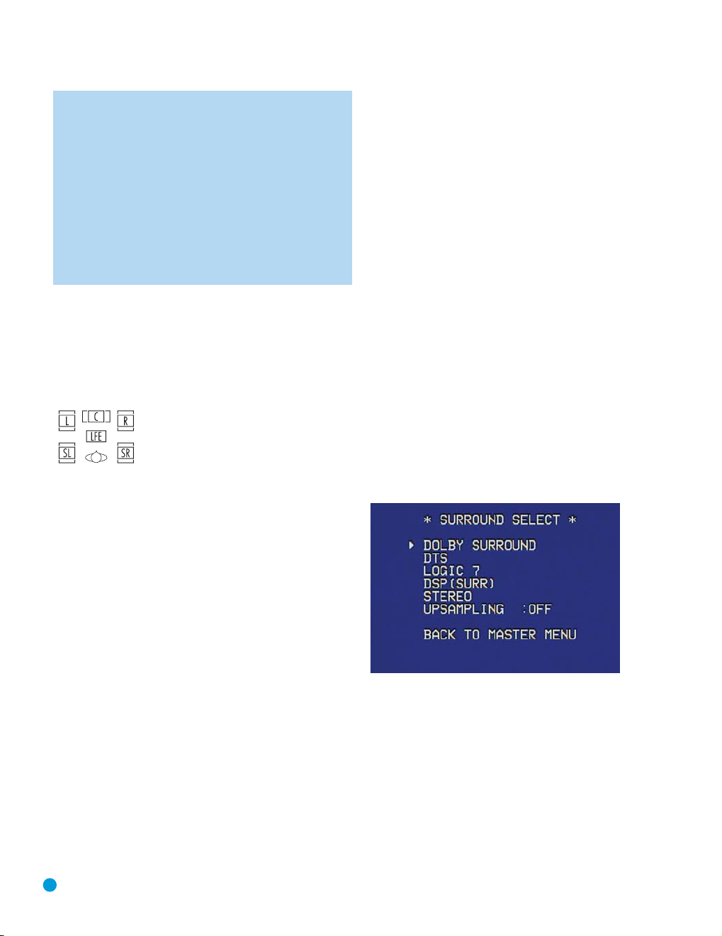
ADVANCED FUNCTIONS
NOTE: The 6.1-channel signals – Dolby Digital EX and DTS-ES
Matrix and Discrete – each include a flag meant to signal the
receiver to decode the surround back channel. For Dolby Digital EX
materials, the incoming bitstream will be displayed as 3/2/.1
EX-ON. For older discs, the display may show EX-OFF. In either
case, since the AVR 144 is not capable of 6.1-channel playback,
the AVR will play the materials in Dolby Digital 5.1 mode.
For DTS-ES materials, the incoming bitstream will be displayed
as 3/3/.1 ES-ON. Again, the materials will only be played in
DTS 5.1 or DTS Neo:6 5-channel mode.
Please refer to Table 4 for more information on which surround
modes are available with different bitstreams.
When a PCM signal is received, the PCM message, followed by the
sampling rate of the signal (44.1kHz, 48kHz or 96kHz), will scroll once
across the front-panel display.
In addition, the Speaker/Channel Input Indicators will indicate the number
of channels discretely encoded in the signal by displaying a letter inside
that channel’s speaker box. See Figure 59. The letters flash when no
signal is present, such as when a DVD is paused.
Figure 59 – Speaker/Channel Input Indicators
Even when only two channels – left and right – are present in the signal, the analog surround modes may be used to decode the signal into
the remaining channels.
As indicated in Table 4, different surround modes may only be available
with certain input signals or bitstream formats. For any incoming signal,
only a limited number of surround modes are available. Although there is
never a time when all of the AVR 144’s surround modes are available,
there is usually a wide variety of modes available for a given input.
There are three methods of manually selecting one of the available surround modes:
1. From the front panel, press the Surround Mode Button until the
desired mode group (Dolby, DTS, DSP, Stereo, Logic 7) is selected,
and the last-used mode from that group will be activated. Then press
the Surround Select Button repeatedly to scroll through the modes
available within that group. See Figure 57.
2. Using the remote, press the button for the desired mode group
(see Figure 58):
Dolby Surr for Dolby modes
DTS Sur for DTS Digital modes
DTS Neo:6 for the DTS Neo:6 modes
Logic 7 for the Logic 7 modes
Stereo for the Stereo or Surround Off modes
Surr for the DSP Surround modes (Hall 1, Hall 2, Theater)
Press the mode button repeatedly to scroll through the modes
available within that group.
3. The full-OSD menu system allows access to submenus for each of
the mode groups through the Surround Select menu. See Figure 60.
Surround Modes
As mentioned in the Introduction to Home Theater section, surround
mode selection is dependent upon the format of the incoming audio
signal, as well as personal taste. There is no harm in experimenting with
all of the modes available with any given source material. Table 4 offers
a brief description of each mode the AVR 144 is capable of using, and
also indicates the types of incoming signals or digital bitstreams the
mode may be used with. Additional information about Dolby and DTS
modes is available on the companies’ Web sites: www.dolby.com and
www.dtsonline.com.
When in doubt, check the jacket of your DVD for more information on
which surround modes are available on the disc. Be aware that usually
nonessential sections of the disc, such as trailers, extra materials or the
disc menu, are only available in Dolby Digital 2.0 (2-channel) or PCM
2-channel mode. If the main title is playing and the letters in the
Speaker/Channel Input Indicators are not lit for all speaker locations,
look for an audio setup section of the disc’s menu. Also, make sure your
DVD player’s audio output is set to the original bitstream rather than just
PCM. Check the DVD player’s output setting by stopping play of the disc
and checking the DVD player’s menu system.
38
Figure 60 – Surround Select Menu Screen
Navigate to the line for the desired surround mode group, and press
the Set Button to access the submenu for that group. In most cases,
the submenu consists of only two lines:
1. A MODE line, which displays the currently selected mode. Use the
‹/› Buttons to scroll through the available modes.
2. A BACK TO SURROUND SELECT line, which may be used to exit the
submenu.
The Dolby Surround submenu adds some advanced settings.
Page 39
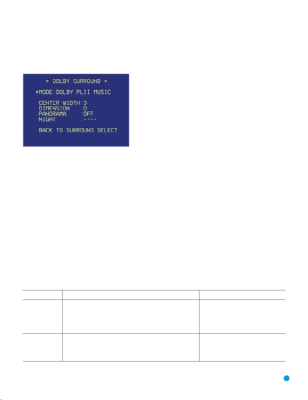
ADVANCED FUNCTIONS
Dolby Surround Settings
In addition to the MODE line, the DOLBY SURROUND submenu includes
three settings that are active only when the Dolby Pro Logic II Music
mode has been selected. See Figure 61.
Figure 61 – Dolby Surround Menu Screen
CENTER WIDTH: This setting affects how vocals sound through the
three front speakers. A higher number (up to 7) focuses the vocal information tightly on the center channel. Lower numbers broaden the vocal
soundstage across the three speakers.
DIMENSION: This setting affects the depth of the surround presentation, allowing you to “move” the sound toward the front or rear of the
room. The setting of “0” is a neutral default. Setting “F-3” moves the
sound mostly toward the front of the room, while setting “R-3” moves
the sound mostly toward the rear.
PANORAMA: With the Panorama mode turned ON, some of the sound
from the front speakers is moved to the surround speakers, creating an
enveloping “wraparound” type of effect.
NIGHT MODE: Night mode is available with some Dolby Digital programs,
if it has been encoded in the material. It compresses the peak sound
levels, maintaining the intelligibility of the dialogue and quieter passages,
while reducing the loudness of special effects and louder passages to
avoid disturbing others. Three levels of compression are available:
OFF: At this setting, there is no compression, as the Night mode is
deactivated.
MID: A mild compression is applied.
MAX: More compression is applied.
We suggest that you experiment with the modes to find a setting that
meets your needs.
The Night mode may also be adjusted without using the full-OSD menu
system. With a Dolby Digital program encoded with Night mode playing,
press the Night Button on the remote. Each press of the button will
cycle through the three settings, with the selected setting being displayed on the front panel and in the semi-OSD display.
UPSAMPLING: The last line of the Surround Select menu activates
upsampling, only available with the Dolby Pro Logic II Movie, Dolby
Pro Logic II Music and Dolby Pro Logic modes. Normally set to OFF,
upsampling, when activated, processes digital sources at a higher
resolution for improved sound quality. This feature can be useful to
eliminate distortion in some low-resolution sources.
Default Modes
During initial use or after a processor reset, the AVR 144 will default
to the Logic 7 Music mode for all analog and PCM audio inputs.
Subsequently, when a source input is selected and an analog or
PCM signal is received, the AVR will switch to the last surround mode
used for that source input/incoming signal combination.
Whenever a multichannel Dolby Digital or DTS signal is detected, the
AVR 144 will automatically switch to that mode, unless the DEFAULT SURR
MODE setting in the System Setup menu has been changed to OFF. You
may observe that other surround modes are available for use with the multichannel digital bitstreams. If you would prefer the AVR 144 to use one of
those alternate modes any time the same digital signal is detected, then
select that mode while the multichannel bitstream is present, and then change
the DEFAULT SURR MODE setting in the System Setup menu to OFF.
Table 4 – Surround Modes
Surround Mode Description Incoming Bitstream or Signal
Dolby Digital Provides up to five separate main audio channels and a dedicated • Dolby Digital 1/0/.0 or .1, 2/0/.0 or .1,
low-frequency effects (LFE) channel. May be encoded for Night mode, 3/0/.0 or .1, 2/1/.0 or .1, 2/2/.0 or .1,
which allows the user to apply a compression setting that maintains 3/2/.0 or .1
intelligibility of softer passages while reducing the loudness of dynamic • Dolby Digital EX (played as 5.1)
passages to avoid disturbing others.
Dolby Digital Stereo Delivers a 2-channel downmix of Dolby Digital materials. • Dolby Digital 1/0/.0 or .1, 2/0/.0 or .1,
3/0/.0 or .1, 2/1/.0 or .1, 2/2/.0 or .1,
3/2/.0 or .1
• Dolby Digital EX
39
Page 40

ADVANCED FUNCTIONS
Surround Mode Description Incoming Bitstream or Signal
Dolby Pro Logic II Analog decoder that derives five full-range, discrete main audio channels See below.
Dolby Pro Logic II Variant of Dolby Pro Logic II that is optimized for movie and • Dolby Digital 2.0 or 2.1
Movie television programs. • Analog (2-channel)
Dolby Pro Logic II Variant of Dolby Pro Logic II that is optimized for music selections. • Dolby Digital 2.0 or 2.1
Music Allows adjustment of sound field presentation in three dimensions: • Analog (2-channel)
Dolby Pro Logic II Variant of Dolby Pro Logic II that emphasizes use of the surround • Dolby Digital 2.0 or 2.1
Game channels and subwoofer for total immersion in the video gaming • Analog (2-channel)
Dolby Pro Logic Original version of Dolby Pro Logic that steered a mono signal • Dolby Digital 2.0 or 2.1
Dolby Virtual Speaker
Dolby Virtual Speaker When fewer than five main speakers are present, the Reference • Dolby Digital (uses only two-speaker mode
Reference mode virtualizes the missing speakers with accurate localization. when s
Dolby Virtual Speaker Wide mode may be used with two, three, four or five • Dolby Digital (number of channels available
Wide main speakers to widen the front soundstage varies by number of channels in signal)
DTS Digital Using a different encoding/decoding method than Dolby Digital, • DTS 1/0/.0 or .1, 2/0/.0 or .1, 3/0/.0 or .1,
DTS Stereo Delivers a 2-channel downmix of DTS Digital materials, or presents • DTS 1/0/.0 or .1, 2/0/.0 or .1, 3/0/.0 or .1,
from matrix surround-encoded or 2-channel analog sources. Four
variants are available.
• Tuner
• PCM (44.1kHz, 48kHz, 96kHz)
• Center Width (adjusts width of vocal soundstage) • Tuner
• Dimension (adjusts depth of soundstage) • PCM (44.1kHz, 48kHz, 96kHz)
• Panorama (adjusts wraparound surround effect)
experience. • Tuner
• PCM (44.1kHz, 48kHz, 96kHz)
containing information below 7kHz to the surround channels. • Analog (2-channel)
• Tuner
• PCM (44.1kHz, 48kHz, 96kHz)
Simulates 5.1 channels when fewer speakers are present, or a more See below.
enveloping sound field is desired.
Select from two- or three-speaker mode, depending on how many
physical speakers are in your system. • Analog (2-channel)
by virtualizing the locations of the left and right speakers. • Analog (2-channel)
it also provides up to 5 discrete main channels, plus an LFE channel. 3/1/.0 or .1, 2/2/.0 or .1, 3/2/.0 or .1
a matrix-encoded surround presentation. 3/1/.0 or .1, 2/2/.0 or .1, 3/2/.0 or .1
ignal does not contain center channel
information)
• Tuner
• PCM (44.1kHz or 48kHz)
• Tuner
• PCM (44.1kHz or 48kHz)
• DTS-ES Matrix (played as 5.1)
• DTS-ES Discrete (played as 5.1)
• DTS 96/24
• DTS-ES Matrix
• DTS-ES Discrete
40
Page 41

ADVANCED FUNCTIONS
Surround Mode Description Incoming Bitstream or Signal
DTS Neo:6 DTS Neo:6 analog processing is available with DTS and DTS 96/24 See below.
DTS Neo:6 Depending on the number of speakers in your system, select 3- or 5-channel • DTS 2/2/.0 or .1, 3/2/.0 or .1
Cinema modes, enhanced for movie or video presentations. • DTS 96/24
DTS Neo:6 Available only in 5-channel mode, creates a surround presentation suitable • DTS 2/2/.0 or .1, 3/2/.0 or .1
Music for music recordings. • DTS 96/24
Logic 7 Exclusive to Harman Kardon, Logic 7 enhances 2-channel recordings by See below.
Logic 7 Especially suited to 2-channel sources containing Dolby Surround or • Analog (2-channel)
Cinema matrix encoding, Logic 7 Cinema mode increases center channel intelligibility. • Tuner
Logic 7 The AVR 144 is programmed at the factory to default to this mode for • Analog (2-channel)
Music 2-channel signals. Logic 7 Music mode is well suited to conventional • Tuner
Logic 7 Logic 7 Enhance circulates low frequencies in the 40Hz – 120Hz range to • Analog (2-channel)
Enhance the main speakers for less localized bass performance than would be achieved • Tuner
Hall 1 Hall 1 is a DSP (digital signal processor) mode that simulates a small • Analog (2-channel)
Hall 2 Simulates a medium-sized concert hall. • Analog (2-channel)
Theater Simulates a live-performance theater. • Analog (2-channel)
5-Channel Stereo Useful for parties, the left- and right-channel information is played through • Analog (2-channel)
DSP Surround Off Turns off all surround processing and plays a pure 2-channel signal. • Analog (2-channel)
Surround Off Maintains an analog input signal in that form, bypassing all digital processing • Analog (2-channel)
(Analog Bypass) (i.e., surround and bass management). Requires TONE OUT setting. • Tuner
signals and 2-channel analog or PCM signals to create a 3- or 5-channel
presentation.
• Analog (2-channel)
• PCM (44.1kHz or 48kHz)
• Analog (2-channel)
• PCM (44.1kHz or 48kHz)
deriving separate information for the surround back channels. This provides
more accurate placement of sound, improves panning and expands the
sound field, even when used with 5.1-channel systems. Logic 7 uses
96kHz processing.
• PCM (44.1kHz, 48kHz, 96kHz)
2-channel music recordings. • PCM (44.1kHz, 48kHz, 96kHz)
solely with a subwoofer. Enhance mode is best used with music recordings. • PCM (44.1kHz, 48kHz, 96kHz)
concert hall. • Tuner
• PCM (44.1kHz or 48kHz)
• Tuner
• PCM (44.1kHz or 48kHz)
• Tuner
• PCM (44.1kHz or 48kHz)
both the front and surround speakers on each side, while the center speaker • Tuner
plays a summed mono mix. • PCM (44.1kHz or 48kHz)
The signal is digitized and bass management settings are applied, making it • Tuner
appropriate when a subwoofer is used. • PCM (44.1kHz, 48kHz, 96kHz)
41
Page 42
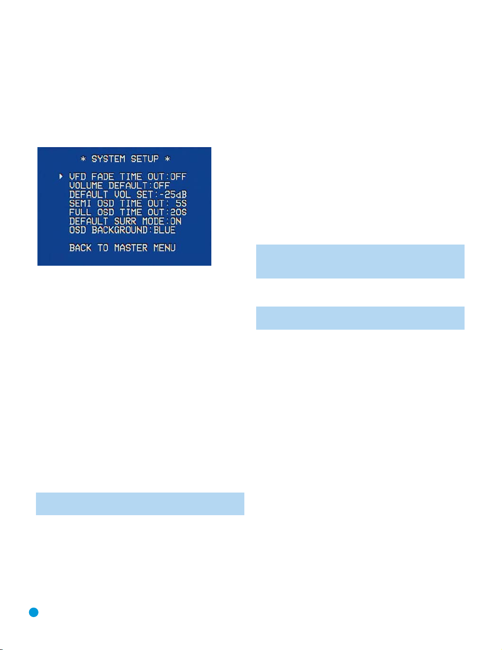
ADVANCED FUNCTIONS
System Settings
The AVR 144 offers several system settings that allow you to make the
receiver easier to use rather than directly affecting performance. Most of
these settings may be accessed from the SYSTEM SETUP menu, which
is selected by pressing the OSD Button and navigating to the SYSTEM
SETUP line of the MASTER MENU. Press the Set Button to display the
submenu. See Figure 62.
Figure 62 – System Setup Menu Screen
VFD FADE TIME OUT: Some people find the brightness of the AVR’s
front-panel display distracting during movies or listening sessions. It’s
possible to dim the front-panel display completely using the Dim function (see below). Alternatively, you may set the display to remain dark
most of the time, lighting up only when a button is pressed or a remote
command is received. This setting allows you to turn on this feature and
program the amount of time the display remains lit before fading to dark.
Select a time-out period of between 3 and 10 seconds, or select OFF
if you prefer to leave the displays either on or dimmed at all times.
VOLUME DEFAULT and DEFAULT VOL SET: These two settings are
used together to program a volume level the AVR will always switch to
when turned on. This feature avoids overtaxing the system in case the
last user turned the volume very high.
Press the OSD Button to remove the display from the screen so that
you may adjust the volume to a desired level while a source is playing.
Make a note of the number that appears in the display, and return to
the SYSTEM SETUP menu. At the DEFAULT VOL SET line, select the
desired volume setting, and activate the feature by setting VOLUME
DEFAULT to ON.
NOTE: Although volume is normally displayed in 0.5dB increments,
the default volume setting only allows whole numbers.
SEMI OSD TIME OUT: At this line, you may program the amount of
time (2 to 5 seconds) the two-line semi-OSD on-screen messages
remain visible, or you may deactivate the semi-OSD display altogether
if you find it distracting. The same messages will continue to appear
on the front panel of the receiver.
FULL OSD TIME OUT: At this line, you may program the amount of
time (20, 30, 40 or 50 seconds) the full-OSD menus remain visible on
screen. The full-OSD system may not be deactivated.
DEFAULT SURR MODE: This setting determines how the AVR 144 will
handle Dolby Digital and DTS sources. For the purposes of this setting,
the “default surround mode” means the mode encoded in the program,
such as Dolby Digital 5.1. With this setting ON, the receiver will always
use the default surround mode in the program. When this setting is
changed to OFF, the receiver will use the surround mode you selected
the last time this type of audio stream was detected.
For an example, the Default Surround Mode setting can be beneficial
when used with Dolby Digital 2.0 programs, such as the ones broadcast
on many channels of some cable and satellite television systems. If you
would prefer to play these programs in the Dolby Pro Logic II Movie
surround mode, then set DEFAULT SURR MODE to OFF, and select your
desired surround mode the first time a Dolby Digital 2.0 program is
played. Dolby Digital 5.1 programs will still be played in 5.1-channel mode.
NOTE: For PCM and analog sources, the factory default surround
mode is Logic 7 Music. In general, the receiver will use the surround mode selected the last time that type of signal was received.
OSD BACKGROUND: This setting allows you to choose between a blue
or black background for the full-OSD menus.
NOTE: It isn’t possible to view video sources while the full-OSD
menus are displayed.
Dim Function
Some people find the front-panel messages distracting and would prefer
to dim them or turn them off altogether.
To dim the display, press the Dim Button on the remote. Each button
press will cycle through the three settings of:
VFD FULL: Normal brightness
VFD HALF: Display is dimmed but still visible; the light inside the vol-
ume knob goes dark
VFD OFF: Display goes completely dark except for Power Indicator to
remind you that the receiver is turned on
Advanced Remote Control Functions
The AVR 144 remote control not only operates the AVR 144, but it also
serves as a universal remote that may be programmed to operate many
of your other home theater components, as described in the Installation
section. Each time you select one of your other components, the AVR
remote switches to the control functions for that component. Since
many buttons will have unique functions for each component, you may
wish to refer to the Function List (Table A8) in the Appendix for assistance in operating your other components. The function of each button
will not necessarily correspond to the label printed on the button.
42
Page 43

ADVANCED FUNCTIONS
Punch-Through Programming
The AVR 144 remote allows you to select one component for the
remote to operate, while simultaneously setting certain groups of controls to operate another component. For example, while using the AVR
to control surround modes and other audio functions, you may wish to
operate the transport controls of your DVD player. Or while using the
remote to control video functions on your TV, you may wish to use your
cable box to change channels and the AVR to control the volume.
All of this is possible using punch-through programming.
NOTE: It is not necessary to program the remote to control
your DVD player’s transport controls while the AVR is in use, as
the remote is preprogrammed at the factory with this function.
To program punch-through control while operating any device:
1. Simultaneously press and hold the Input Selector (or AVR selector)
for the main device the remote will be operating and the Mute Button
until the LED flashes and the remote enters program mode.
2. Select the type of punch-through programming.
a) To program volume-control punch-through, press the Volume Up
Button.
b) To program channel-control punch-through, press the Volume
Down Button.
c) To program transport-control punch-through, press the Play Button.
3. Press the Input Selector (or AVR selector) for the device whose volume,
channel or transport controls you would like to be active while operating
the device you selected in the first step. The LED will flash green to
confirm the programming.
For example, if you wish to watch your TV (programmed into the Video
3 Button) while changing channels using your cable box (Video 2), you
would first press the Video 3 and Mute Buttons until the LED flashed.
You would then press the Volume Down Button, followed by the Video 2
Button.
To undo punch-through programming, follow the same steps as above,
but press the same Input (or AVR) Selector in steps 1 and 3.
Macros
Macros are used to program sequences of up to nineteen commands
that are executed with a single button press. Macros are well-suited for
power on and off commands, or to send out a favorite multi-digit channel
number with one button press, or to have the ability to send out a code
sequence to control another device while the remote is operating one
device but with more flexibility than the built-in punch-through controls.
Some commands may not be programmed into macros: Mute, Dim,
Channel Up/Down, any of the surround mode commands.
NOTE: Use caution when programming complicated macros. It
isn’t possible to program a pause or delay before sending commands after Power On, and the component may not be ready
to respond to commands instantaneously after powering on.
To program, or “record” a macro, follow these steps:
1. Simultaneously press one of the four Macro Buttons or the Power On
Button and the Mute Button at the same time to enter program mode.
2. Press the Input (or AVR) Selector for each device before you enter
commands to be transmitted to that device. This step counts as one
of the 19 commands allowed for each macro.
3. For the Power On command, do not press the Power On Button.
Press the Mute Button instead.
4. Press the Power Off Button to program the Power Off command.
5. Press the Sleep Button to end the programming process.
It isn’t possible to “edit” a command within a macro. However, you may
erase the macro as follows:
1. Simultaneously press and hold the Mute Button and the Macro
Button containing the macro until the LED flashes.
2. Press the Surround Button to erase the macro.
Resetting the Remote
To reset the remote to its factory defaults, enter Program mode by
simultaneously pressing and holding any Input Selector and the Mute
Button. When the LED flashes, enter the code “333”. When the LED
goes out, the remote will have been fully reset.
Processor Reset
If you wish to fully reset the AVR 144 to its factory defaults, or if it behaves
erratically after a power surge, first turn the Master Power Switch off and
unplug the AC Power Cord for at least three minutes. Plug the cord back
in and turn the receiver back on. If this doesn’t help, you may want to
try a system reset.
A system reset erases all user configurations, including
NOTE:
speaker and level settings and tuner presets. After a reset, you
will need to reenter all of these settings.
Place the receiver in Standby mode by pressing the Standby/On Switch
so that the Power Indicator turns amber. Press and hold the front-panel
Surround Mode and Surround Select Buttons simultaneously for at least
five seconds until the RESET message appears in the display.
If the receiver still does not function correctly after a processor reset,
contact an authorized Harman Kardon service center for assistance.
Authorized service centers may be located by visiting our Web site
at www.harmankardon.com.
Memory
If the AVR 144 is unplugged or experiences a power outage, it will retain
user settings for up to four weeks.
43
Page 44

TROUBLESHOOTING GUIDE
SYMPTOM CAUSE SOLUTION
Unit does not function when Main • No AC Power • Make certain AC power cord is plugged into
Power Switch is pushed a live outlet
Display lights, but no sound • Intermittent input connections • Make certain that all input and speaker connections
or picture are secure
• Mute is on • Press Mute Button
• Volume control is down • Turn up volume control
No sound from any speaker; • Amplifier is in protection mode • Check speaker wire connections for shorts at receiver and
light around power switch is red due to possible short speaker ends
• Amplifier is in protection mode • Contact your local Harman Kardon service center
due to internal problems
No sound from surround or • Incorrect surround mode • Select a mode other than Stereo
center speakers • Input is monaural • There is no surround information from mono sources
• Incorrect configuration • Check speaker mode configuration
• Stereo or Mono program material • The surround decoder may not create center- or rear-channel
Unit does not respond to • Weak batteries in remote • Change remote batteries
remote commands • Wrong device selected • Press the AVR selector
• Remote sensor is obscured • Make certain front panel sensor is visible to remote
Intermittent buzzing in tuner • Local interference • Move unit or antenna away from computers, fluorescent
Letters flash in the channel indicator • Digital audio feed paused • Resume play for DVD
display and digital audio stops • Check that Digital Input is selected
In addition to the items shown above, additional information on troubleshooting possible problems with your AVR 144, or installation-related issues, may
be found in the list of "Frequently Asked Questions" which is located in the Product Support section of our Web site at www.harmankardon.com.
• Check to see whether outlet is switch-controlled
information from nonencoded programs
or connect an optional remote sensor
lights, motors or other electrical appliances
44
Page 45

AVR 144 TECHNICAL SPECIFICATIONS
Audio Section
Stereo Mode
Continuous Average Power (FTC)
40 Watts per channel, 20Hz–20kHz,
@ <0.07% THD, both channels driven into 8 ohms
Five-Channel Surround Modes
Power per Individual Channel
Front L&R channels:
30 Watts per channel
@ <0.07% THD, 20Hz–20kHz into 8 ohms
Center channel:
30 Watts @ <0.07% THD, 20Hz–20kHz into 8 ohms
Surround (L & R Side) channels:
30 Watts per channel
@ <0.07% THD, 20Hz–20kHz into 8 ohms
Input Sensitivity/Impedance
Linear (High-Level) 200mV/47k ohms
Signal-to-Noise Ratio (IHF-A) 100dB
Surround System Adjacent Channel Separation
Pro Logic I/II 40dB
Dolby Digital (AC-3) 55dB
DTS 55dB
Frequency Response
@ 1W (+0dB, –3dB) 10Hz –130kHz
High Instantaneous
Current Capability (HCC) ±25 Amps
Transient Intermodulation
Distortion (TIM) Unmeasurable
Slew Rate 40V/μsec
FM Tuner Section
Frequency Range 87.5–108.0MHz
Usable Sensitivity IHF 1.3μV/13.2dBf
Signal-to-Noise Ratio Mono/Stereo 70/68dB
Distortion Mono/Stereo 0.2/0.3%
Stereo Separation 40dB @ 1kHz
Selectivity ±400kHz, 70dB
Image Rejection 80dB
IF Rejection 90dB
AM Tuner Section
Frequency Range 520–1720 kHz
Signal-to-Noise Ratio 45dB
Usable Sensitivity Loop 500 μV
Distortion 1kHz, 50% Mod 0.8%
Selectivity ±10kHz, 30dB
Video Section
Television Format NTSC
Input Level/Impedance 1Vp-p/ 75 ohms
Output Level/Impedance 1Vp-p/75 ohms
Video Frequency Response
(Composite and S-Video) 10Hz–8MHz (–3dB)
Video Frequency Response
(Component Video) 10Hz–100MHz (–3dB)
General
Power Requirement AC 120V/60Hz
Power Consumption 65W idle, 540W maximum
(5 channels driven)
Dimensions (Product) (Shipping)
Width 17-5/16 inches (440mm) 21-7/8 inches (555mm)
Height 6-1/2 inches (165mm) 10-1/2 inches (266mm)
Depth 15 inches (382mm) 18-5/16 inches (465mm)
(Product) (Shipping)
Weight 21.12 lb (9.6kg) 26 lb (11.8kg)
Depth measurement includes knobs, buttons and terminal connections.
Height measurement includes feet and chassis.
All features and specifications are subject to change without notice.
Harman Kardon, Harman International and Logic 7 are trademarks of Harman International Industries,
Incorporated, registered in the United States and/or other countries. Designed to Entertain is a trademark
of Harman International Industries, Incorporated.
Dolby, Pro Logic and the double-D symbol are trademarks of Dolby Laboratories.
Manufactured under license from Dolby Laboratories.
“DTS,” “DTS Surround,” “DTS-ES
“96/24” is a trademark, of DTS, Inc.
Cirrus Logic is a registered trademark of Cirrus Logic, Inc.
SACD is a trademark of Sony Corporation.
Blu-ray Disc is a trademark of the Blu-ray Disc Association.
HD-DVD is a trademark of the DVD Format/Logo Licensing Corporation (DVD FLLC).
TiVo is a registered trademark of TiVo Inc.
Neo:6” are registered trademarks of DTS, Inc.
I
Please register your product on our Web site at www.harmankardon.com. Note: You’ll need the product’s serial number.
At the same time, you can choose to be notified about our new products and/or special promotions.
45
Page 46

APPENDIX
Appendix – Default Settings, Worksheets, Remote Product Codes
Table A1 – Source Input Setting Defaults
Source DVD Video 1 Video 2 Video 3 CD Tape Tuner 6-Channel
Title INT. TUNER
Component Comp V 1 Comp V 2 Comp V 2 Comp V 2 Comp V 1 Comp V 1 Comp V 1 Comp V 1
Video Input
Audio Input Coax 1 Analog Optical 1 Analog Analog Analog Tuner 6-Channel
Auto Poll On On On On On On --- ---
Surround Logic 7 Logic 7 Logic 7 Logic 7 Logic 7 Logic 7 Logic 7 Logic 7
Mode* 5CH Music 5CH Music 5CH Music 5CH Music 5CH Music 5CH Music 5CH Music 5CH Music
*The default shown is the preferred surround mode for PCM and Analog audio sources.
Table A2 – Speaker/Channel Setting Defaults
Source DVD Video 1 Video 2 Video 3 CD Tape Tuner 6-Channel
Bass Manager: Global
Left/Right Speaker Size Small Small Small Small Small Small Small Large
Center Speaker Size Small Small Small Small Small Small Small Large
Surround Speaker Size Small Small Small Small Small Small Small Small
Subwoofer Sub Sub Sub Sub Sub Sub Sub Sub
Left/Right Speaker Crossover 100Hz 100Hz 100Hz 100Hz 100Hz 100Hz 100Hz 100Hz
Center Speaker Crossover 100Hz 100Hz 100Hz 100Hz 100Hz 100Hz 100Hz 100Hz
Surround Speaker Crossover 100Hz 100Hz 100Hz 100Hz 100Hz 100Hz 100Hz 100Hz
Subwoofer Crossover Left/Right Left/Right Left/Right Left/Right Left/Right Left/Right Left/Right Left/Right
Table A3 – Delay Setting Defaults
Speaker Position Distance From Speaker to Listening Position Your Delay Settings
Front Left 10 feet
Center 10 feet
Front Right 10 feet
Surround Right 10 feet
Surround Left 10 feet
Subwoofer 10 feet
A/V Sync Delay 0mS
46
Page 47

APPENDIX
Table A4 – Source Input Settings
Source DVD Video 1 Video 2 Video 3 CD Tape Tuner 6-Channel**
Title INT. TUNER
Video Input
Component Video Input
Audio Input Tuner 6-Channel
Auto Poll --- ---
Surround Mode
Table A5 – Speaker/Channel Settings
Source DVD Video 1 Video 2 Video 3 CD Tape Tuner 6-Channel
Bass Manager:
Global/Independent N/A
Left/Right Speaker Size N/A
Center Speaker Size N/A
Surround Speaker Size N/A
Subwoofer N/A
Left/Right Speaker Crossover N/A
Center Speaker Crossover N/A
Surround Speaker Crossover N/A
Subwoofer Crossover N/A
Left/Right Channel Level***
Center Channel Level***
Surround Channel Level***
Subwoofer Channel Level***
**The 6-Channel Inputs are “direct” inputs, meaning their signals are passed directly to the volume control without any bass management processing.Thus, the speaker sizes are always full range,
and it isn’t possible to adjust speaker size or crossover.
***Note: Channel levels vary by surround mode rather than source input.
47
Page 48

APPENDIX
Table A6 – Remote Control Codes
Source Input Product Type (circle one) Remote Control Code
Video 1 VCR, PVR
Video 2 Cable, Satellite
Video 3 TV
DVD DVD
CD CD, CDR
Tape Cassette
Table A7 – System Settings
Feature Default Setting Your Setting
VFD Fade Time-Out Off
Volume Default Off
Default Vol Set –25dB
Semi-OSD Time-Out 5 Seconds
Full-OSD Time-Out 20 Seconds
Default Surr Mode On
OSD Background Blue
48
Page 49
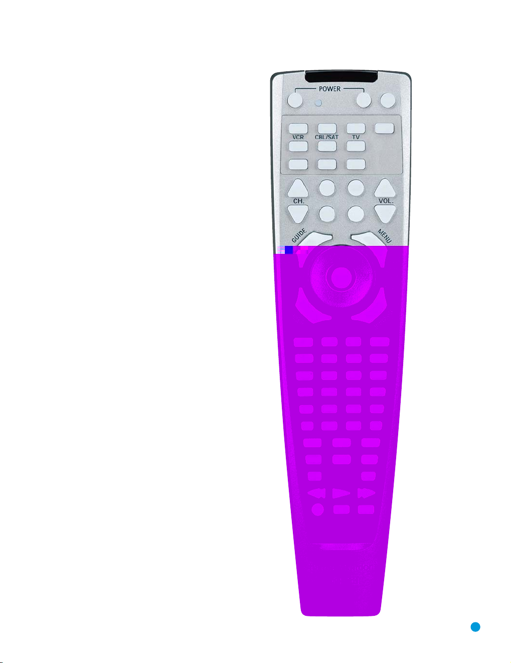
1
2
4567
8910
11 12 13
14 17
15 16
18 21
19 20
22 23
29
30
31 32 33 34
35 36 37 38
39 40 41 42
43 44 45 46
47 48 49 50
51
52 53
55 56 57
58 59 60
61 62
63 64 65
66 67 68
54
24
26 2725
28
3
APPENDIX
Refer to the numbered buttons in Figure 63 when using the Function List.
Figure 63 – Remote Control Function List Reference
49
Page 50

APPENDIX
Table A8 – Remote Control Function List
No. Button Name AVR Function DVD CD/CD-R Tape VCR (VID1) TiVo (VID1) CBL (VID2) SAT (VID2) TV (VID3)
1 Power On Power On Power On Power On Power On Power On/Off Power On Power On Power On
2 Power Off Power Off Power Off Power Off Power Off TV Power Power Off Power Off Power Off
3 Mute Mute Mute Mute Mute Mute Mute Mute Mute Mute
4 AVR AVR Select AVR Select AVR Select AVR Select AVR Select AVR Select AVR Select AVR Select AVR Select
5 DVD DVD Input Select DVD Select DVD Select DVD Select DVD Select DVD Select DVD Select DVD Select DVD Select
6 CD CD Input Select CD Select CD Select CD Select CD Select CD Select CD Select CD Select CD Select
7 Ta pe Tape Input Select Tape Select Tape Select Tape Select Tape Select Tape Select Tape Select Tape Select Tape Select
8 VID 1 (VCR) Video 1 Select VCR Select VCR Select VCR Select VCR Select VCR Select VCR Select VCR Select VCR Select
9 VID 2 (CBL/SAT) Video 2 Select CBL/SAT Select CBL/SAT Select CBL/SAT Select CBL/SAT Select CBL/SAT Select CBL Select SAT Select CBL/SAT Select
10 VID 3 (TV) Video 3 Select TV Select TV Select TV Select TV Select TV Select TV Select TV Select TV Select
11 DIM Dimmer
12 AM/FM Tuner Select Tuner Select Tuner Select Tuner Select Tuner Select Tuner Select Tuner Select Tuner Select Tuner Select
13 6CH 6/8 Ch. Input Select 6/8 Ch. Input Select 6/8 Ch. Input Select 6/8 Ch. Input Select
14 Sleep/CH+ Sleep Audio Channel + Channel + Channel + Channel + Channel +
15 Test Test Tone
16 T/V TV/DVD or V. OFF Input Select TV/VCR TV Input TV/CBL TV/SAT TV/VCR
17 Vol Up Volume Up Volume Up Volume Up Volume Up Volume Up Volume Up Volume Up Volume Up
18 Surr/CH–
19 OSD OSD Program OSD Live TV OSD OSD OSD
20 Blank HD Mode
21 Vol Down Volume Down Volume Down Volume Down Volume Down Volume Down Volume Down Volume Down Volume Down
22 CH./Guide Channel Trim Title or Disc Menu Continuous Play Guide Info/Guide Info/Guide
23 Speaker/Menu Speaker Setup Menu or Setup Intro Scan Menu Menu Menu Menu Menu
⁄
24
25 fi Move/Adjust Left Left Left Left Left Left Left
26 Set Set Enter Enter Select Enter Enter Enter
27 fl Move/Adjust Right Right Right Right Right Right Right
¤
28
29 Digital/Exit Digital Input Select Open/Close Return/Exit
30 Delay/Prev. Ch. Delay Adjust Return or Status Open/Close Prev Channel Prev Channel Prev Channel
31 1 111 11111
32 2 222 22222
33 3 333 33333
34 4 444 44444
35 5 555 55555
36 6 666 66666
37 7 777 77777
38 8 888 88888
39 Tun-M Tunning Mode Chapter+ or Zoom Repeat
40 9 999 99999
41 0 000 00000
42 Memory Memory Audio or Playlist Time
43 Tuning Up Tuning Up Next Chapter Track Direct Cancel Cancel Sleep
DSP Surround Mode Select
Move/Adjust Up Up Up Up Up Up Up
Move/Adjust Down Down Down Down Down Down Down
Disc Menu or Title CDR Select Channel – Channel – Channel – Channel – Channel –
6/8 Ch. Input Select
6/8 Ch. Input Select
6/8 Ch. Input Select 6/8 Ch. Input Select 6/8 Ch. Input Select
50
Page 51

APPENDIX
No. Button Name AVR Function DVD CD/CD-R Tape VCR (VID1) Tivo (VID1) CBL (VID2) SAT (VID2) TV (VID3)
44 Direct Direct Tuner Entry Angle Random Play FAV/Angle FAV
45 Clear Clear Clear Clear Clear Clear Next
46 Preset Up Preset Tune Up Slow Forward +10 Alt
47 Tuning Down Tuning Down Prev Chapter Track Increment
48 Tone Tone mode Program
49 D. Skip Disc Skip (DVD) Disc Skip Disc Skip Skip
50 Preset Down Preset Tune Down Slow Rev
51 M1 Macro 1 Macro 1 Macro 1 Macro 1 Macro 1 Macro 1 Macro 1 Macro 1 Macro 1
52 M2 Macro 2 Macro 2 Macro 2 Macro 2 Macro 2 Macro 2 Macro 2 Macro 2 Macro 2
53 M3 Macro 3 Macro 3 Macro 3 Macro 3 Macro 3 Macro 3 Macro 3 Macro 3 Macro 3
54 M4 Macro 4 Macro 4 Macro 4 Macro 4 Macro 4 Macro 4 Macro 4 Macro 4 Macro 4
55 Dolby Surround Dolby Modes
56 DTS Surround DTS Digital Modes
57 DTS Neo:6 DTS Neo:6 Select
58 Night Night Mode Select Subtitle On/Off CDP Select
59 Logic 7 Logic 7 Select
60 Stereo Stereo Mode Select
61 Skip Down Skip – (DVD) Step – Skip – Scan – Thumbs Down Skip – (DVD) Skip – (DVD) Skip – (DVD)
62 Skip Up Skip + (DVD) Step + Skip + Scan + Thumbs Up Skip + (DVD) Skip + (DVD) Skip + (DVD)
63 Rewind (‹‹) R. Search (DVD) R. Search R. Search Rewind Rewind R. Search R. Search (DVD) R. Search (DVD) R. Search (DVD)
64 Play (‹›) Play (DVD) Play Play R. Play/F. Play Play Play Play (DVD) Play (DVD) Play (DVD)
65 F F (››) F. Search (DVD) F. Search F. Search Fast Fwd Fast Fwd F. Search F. Search (DVD) F. Search (DVD) F. Search (DVD)
66 Record Record Record/Pause Record Record
67 Stop Stop (DVD) Stop Stop Stop Stop Slow Stop (DVD) Stop (DVD) Stop (DVD)
68 Pause Pause (DVD) Pause Pause Pause Pause Pause (DVD) Pause (DVD) Pause (DVD)
51
Page 52

APPENDIX
Refer to Tables A9 through A15 when programming the codes for your components into the remote.
Table A9 – Remote Control Product Codes – TV
Manufacturer/Brand Setup Code Number
AIWA 027
A MARK 122 132
ADMIRAL 192
AKAI 123 160
AMPRO 164
ANAM 045 109 122
AOC 122 123 128
BLAUPUNKT 084
BROKSONIC 205 206
CANDLE 123 128
CAPEHART 059
CENTURION 123 171
CENTRONIC 045
CITIZEN 045 123 128 132
CLASSIC 045
CONCERTO 128
CONTEC 045
CORANDO 172
CORONADO 132
CRAIG 045 157 158 159
CROWN 045 132
CURTIS MATHES 123 128 132
CXC 045
DAEWOO 045 087 102 105 108 111 116 127 128 132
DAYTRON 128 132
DIGI LINK 200
DYNASTY 045
DYNATECH 063
ELECTROHOME 115 132
EMERSON 045 123 128 132 139 157 158 159 162 205
FUNAI 045
FUTURETECH 045
GE 029 087 121 123 128 133 144 159 163
GOLDSTAR/LG 110 122 128 132
GRUNDIG 193
HALL MARK 128
HARMAN KARDON 201
HITACHI 123 128 132 147
INFINITY 148
INKEL 120
JBL 148
JC PENNEY 115 123 128 132 144
JENSEN 019
JVC 079 087 134
KAWASHO 173
KEC 045
KENWOOD 123 204
KMC 132
KTV 045 123 132 162
LLOYTRON 172 173
LODGENET 069
52
Page 53

Manufacturer/Brand Setup Code Number
LOGIK 069
LUXMAN 128
LXI 077 144 148
MAGNAVOX 030 123 128 132 144 148
MARANTZ 115 123 148
MATSUI 148
MEMOREX 069 128
METZ 084
MGA 115 123 128
MINERVA 084
MITSUBISHI 077 115 123 128 160 167 168
MTC 175 176
NATIONAL 148 177 180 181 182
NEC 115 121 123
NIKEI 045
ONKING 045
ONWA 045
OPTONICA 077
ORION 207 208 209 210 211
PANASONIC 087 148 180
PHILCO 045 115 123 128 132 148
PHILIPS 033 035 036 123 128 132 144 148
PIONEER 024 123 128
PORTLAND 128 132
PROSCAN 133
PROTON 059 122 128 132 165
QUASAR 032 087
RADIO SHACK 045 123 128 132 180 196
RCA 115 123 128 133 144 163
REALISTIC 045 167 196
RUNCO 152
SAA 183
SAMPO 059 123 128
SAMSUNG 020 022 124 128 132 144
SANYO 026
SCOTT 045 128 132
SEARS 128 132 144
SHARP 077 128 132
SIEMENS 084
SIGNATURE 069
SONY 028 130 136 194 212
SOUNDESIGN 045 128
SPECTRICON 122
SSS 045
SYLVANIA 025 123 128 144 148
SYMPHONIC 184
TANDY 077
TATUNG 063
TECHNICS 181
TECHWOOD 128
APPENDIX
53
Page 54
APPENDIX
Manufacturer/Brand Setup Code Number
TEKNIKA 045 069 115 123 128 132
TELERENT 069
TERA 156
THOMSON 190 191
TMK 128
TOSHIBA 063 129 202
TOTEVISION 132
VIDEO CONCEPTS 160
VIDTECH 128
WARDS 069 128 132 148
YAMAHA 123 128
YORK 128
YUPITERU 045
ZENITH 069 090
ZONDA 122
54
Page 55

Table A10 – Remote Control Product Codes – VCR
Manufacturer/Brand Setup Code Number
AIWA 040
AKAI 048 108 109 126
AMPRO 076
ASA 134
AUDIO DYNAMICS 018 048
BROKSONIC 110 147
CANDLE 134 135
CANON 135 140
CAPEHART 094
CITIZEN 134
CRAIG 045 116
DAEWOO 017 094 104
DAYTRON 094
DBX 018 048
DYNATECH 040
EMERSON 013 040 042 110 112
FISHER 017
FUNAI 040
GE 076 095 124
GO VIDEO 113
GOLDSTAR/LG 018 107
HARMAN KARDON 002 003 018 049
HITACHI 040 048
JC PENNEY 018 045
JENSEN 048
JVC 018 048 111 132
KENWOOD 020 048
LLOYD 040
LXI 020 040
MAGIN 045
MAGNAVOX 040
MARANTZ 018
MEMOREX 017 020 040 053 054 076 142
MGA 049
MITSUBISHI 049 131
MULTITECH 040
NAD 139
NATIONAL 140
NEC 018 048
NORDMENDE 048
OPTIMUS 159
ORION 147
PANASONIC 125 150 167 172
PHILCO 040
PHILIPS 040 075
PORTLAND 094
PULSAR 076
QUASAR 001 125
RADIO SHACK 055 134 140 142 158 159
RCA 095 124 125 157 172
APPENDIX
55
Page 56

APPENDIX
Manufacturer/Brand Setup Code Number
REALISTIC 017 020 040 045 159
SALORA 020
SAMSUNG 045 095 105 109
SANSUI 048 116 147
SANYO 017 020
SCOTT 110 112
SEARS 017 020
SHARP 129 156
SONY 080 129
SOUNDESIGN 040
SYLVANIA 040
SYMPHONIC 040
TANDY 017 040
TASHICO 134
TATUNG 048
TEAC 040 048
TEKNIKA 040
THOMAS 040
TiVo 003 004 005 006 007 008 009 010 012
TMK 013
TOSHIBA 112 155
TOTEVISION 045
UNITECH 045
VECTOR RESEARCH 018
VIDEO CONCEPTS 018 040
VIDEOSONIC 045
WARDS 040 045 112
YAMAHA 018 040 048
ZENITH 040 050 076 083
56
Page 57

Table A11 – Remote Control Product Codes – CD
Manufacturer/Brand Setup Code Number
ADCOM 063 069
AIWA 072 111 118 156 170
AKAI 050 177 184
AUDIO TECHNICA 053
AUDIOACCESS 125
AUDIOFILE 211
BSR 044
CALIFORNIA AUDIO 109
CAPETRONIC 070
CARRERA 087
CARVER 136 140 141 143 144 144 185 186
CASIO 117 166
CLARINETTE 166
DENON 187 188 213
EMERSON 052 093 108
FISHER 055 095
FRABA 117
FUNAI 126
GE 164
GENEXXA 108
GOLDSTAR/LG 087
HAITAI 099 214
HARMAN KARDON 001 002 025 054 190
HITACHI 093
INKEL 216
JC PENNEY 098 147
JENSEN 153
JVC 176 195 196
KENWOOD 030 062 078 079 148 151 176 178 181
LOTTE 108
LUXMAN 077 102
LXI 164
MAGNAVOX 039 113
MARANTZ 058 084 191 192 193
MCINTOSH 194
MCS 080 098
MITSUMI 152
MODULAIRE 166
NAD 013 074 197 198
NAKAMICHI 199 200 201
NEC 069
NIKKO 053 055
ONKYO 037 038 045 046 171 175 202 203
OPTIMUS 065 089 091 092 099 104 212
PANASONIC 075 109 119 158 183 204
PHILIPS 039 138 149 209
PIONEER 071 094 100 112 123 131 161 162 215
PROTON 210
QUASAR 109
RADIO SHACK 126 166 213
RCA 024 081 093 150
APPENDIX
57
Page 58

APPENDIX
Manufacturer/Brand Setup Code Number
RCX 169
REALISTIC 058 093 095 104 105 108 164 166
SANSUI 047 081 134 157 172
SANYO 033 082 095
SCOTT 108
SHARP 058 105 114 151 159 167 180 181
SHERWOOD 003 041 058 105 133
SONY 103 115 116 118 132 139 163 205 206 207 208 212 217
SOUNDSTREAM 124
SYMPHONIC 059 110
TAEKWANG 177
TEAC 011 058 085 086 106 107 110 121 137 146 154
THETA DIGITAL 039
TOSHIBA 013 074 097 151 155 173
VECTOR RESEARCH 087
VICTOR 120 130
WARDS 095
YAMAHA 019 031 053 061 135 169
YORK 166
Table A12 – Remote Control Product Codes – DVD
Manufacturer/Brand Setup Code Number
APEX DIGITAL 061
DENON 019 051
GE 003 004
GOLDSTAR/LG 005 055 064 066
HARMAN KARDON 001 002
JVC 006
MAGNAVOX 056
MARANTZ 059
MITSUBISHI 023
NAD 062
ONKYO 009 048
PANASONIC 024 030 044
PHILIPS 056
PIONEER 041 065
PROCEED 060
PROSCAN 003 004
RCA 003 004
SAMSUNG 053 054
SHARP 028
SONY 043 045
THOMSON 003 004
TOSHIBA 009 058 067
YAMAHA 030 063
ZENITH 005 055 064
58
Page 59

APPENDIX
Table A13 – Remote Control Product Codes – SAT
Manufacturer/Brand Setup Code Number
ALPHASTAR 472
ALPHASTAR DBS 450
ALPHASTAR DSR 442
BIRDVIEW 425
CHANNEL MASTER 320 321 325 361
CHAPARRAL 315 316 451
CITOH 360
DRAKE 313 317 318 413
DX ANTENNA 331 352 379 483
ECHOSTAR 395 397 452 453 463 478 484 485
ELECTRO HOME 392
FUJITSU 324 329 334
GENERAL INSTRUMENT 303 311 323 365 403 454 468 474
HITACHI DBS 455
HOUSTON TRACKER 463
HUGHES 437 489
JANIEL 366
JERROLD 454 468 484
KATHREIN 410
LEGEND 453
MACOM 317 365 369 370 371
MAGNAVOX 461 473
MEMOREX 453
NEXTWAVE 423
NORSAT 373
OPTIMUS 466
PACE DSS 487
PANASONIC 366 469
PANASONIC DBS 457
PANSAT 420
PERSONAL CABLE 418
PHILIPS 375
PICO 407
PRESIDENT 381 404
PRIMESTAR 302 412 454 468
RCA 301 465 490
RCA DSS 458
REALISTIC 349 480
SAMSUNG 442
SATELLITE SERVICE CO 335 388
SCIENTIFIC ATLANTA 339
SONY 405
STAR CHOICE DBS 459
STARCAST 347
SUPER GUIDE 327 423
TELECOM 330 333 390 391 393 409
TOSHIBA 302 461 462
UNIDEN 323 332 348 349 350 351 354 355 381 383 389 403 466 479 480
ZENITH 384 385 387 394 419 488
59
Page 60

APPENDIX
Table A14 – Remote Control Product Codes – TAPE
Manufacturer/Brand Setup Code Number
HARMAN KARDON 001
Table A15 – Remote Control Product Codes – CBL
Manufacturer/Brand Setup Code Number
ABC 001 011
ALLEGRO 111
AMERICAST 212
ARCHER 112
BELCOR 113
CABLE STAR 113
CITIZEN 111
COLOUR VOICE 085 090
DIGI 114
EAGLE 186
EASTERN 066 070
ELECTRICORD 039
EMERSON 112
FOCUS 116
G.I. 001 011 017 096 097
GC ELECTRONICS 113
GEMINI 032 060
GENERAL 210
GENERAL INSTRUMENT 210
GOODMIND 112
HAMLIN 056 099 100 101 117 175 208
HITACHI 001 188
JASCO 111
JERROLD 001 002 011 017 096 097 162 188 210
LINDSAY 118
MACOM 191
MAGNAVOX 017 019 068
MOVIE TIME 039
NSC 190
OAK 197 220
PACE 179
PANASONIC 053 176 177 189 214
PANTHER 114
PHILIPS 013 019 020 085 090
PIONEER 001 171 209 215 216
POPULAR MECHANICS 116
PRELUDE 120
PRIMESTAR 162
RADIO SHACK 111 112 213
RCA 053 214
RECOTON 116
REGAL 056 099 100 101 208
60
Page 61

Manufacturer/Brand Setup Code Number
REMBRANT 032
SAMSUNG 003 072 186
SCIENTIFIC ATLANTA 183 203 221 222
SEAM 121
SIGNATURE 001 188
SPRUCER 053 177 189
STARCOM 002 011 163
STARGATE 120
TANDY 024
TELECAPATION 028
TEXSCAN 036
TFC 122
TIMELESS 123
TOCOM 170 205
UNITED CABLE 011
UNIVERSAL 039 042 113
VIDEOWAY 124 211
VIEWSTAR 019 025 053 089 190
ZENITH 065 211 219
ZENTEK 116
APPENDIX
61
Page 62

NOTES
62
Page 63

NOTES
Page 64

®
250 Crossways Park Drive, Woodbury, New York 11797
www.harmankardon.com
© 2006 Harman International Industries, Incorporated. All rights reserved.
Part No. CQX1A1153Z
 Loading...