

Aanalog and digital systems 246ix, 245ix User Manual

analog and digital systems
245ix
246ix
owner's manual

table of contents
introduction . . . . . . . . . . . . . . . . . . . . . . . . . . . . . . . . . . . . . . . . . . . . . . . . . . . . .1
about this manual . . . . . . . . . . . . . . . . . . . . . . . . . . . . . . . . . . . . . . . . . . . . . . . .1
features . . . . . . . . . . . . . . . . . . . . . . . . . . . . . . . . . . . . . . . . . . . . . . . . . . . . . . . .2
cautions . . . . . . . . . . . . . . . . . . . . . . . . . . . . . . . . . . . . . . . . . . . . . . . . . . . . . . . .2
installation planning . . . . . . . . . . . . . . . . . . . . . . . . . . . . . . . . . . . . . . . . . . . . . . .3
amplifier requirements . . . . . . . . . . . . . . . . . . . . . . . . . . . . . . . . . . . . . . . . . . . . .3
mounting locations . . . . . . . . . . . . . . . . . . . . . . . . . . . . . . . . . . . . . . . . . . . . . . .3
crossover features and connections . . . . . . . . . . . . . . . . . . . . . . . . . . . . . . . . . . .4
speaker wiring . . . . . . . . . . . . . . . . . . . . . . . . . . . . . . . . . . . . . . . . . . . . . . . . . . .5
speaker installation . . . . . . . . . . . . . . . . . . . . . . . . . . . . . . . . . . . . . . . . . . . . . . .6
tweeter installation . . . . . . . . . . . . . . . . . . . . . . . . . . . . . . . . . . . . . . . . . . . . . . .6
crossover installation . . . . . . . . . . . . . . . . . . . . . . . . . . . . . . . . . . . . . . . . . . . . .10
connecting the system . . . . . . . . . . . . . . . . . . . . . . . . . . . . . . . . . . . . . . . . . . . .11
crossover connections and input switch setting . . . . . . . . . . . . . . . . . . . . . . . . .11
bi-amplified connections to crossover . . . . . . . . . . . . . . . . . . . . . . . . . . . . . . . . .12
bi-wire connections to crossover . . . . . . . . . . . . . . . . . . . . . . . . . . . . . . . . . . . .13
troubleshooting . . . . . . . . . . . . . . . . . . . . . . . . . . . . . . . . . . . . . . . . . . . . . . . . .14
specifications . . . . . . . . . . . . . . . . . . . . . . . . . . . . . . . . . . . . . . . . . . . . . . . . . . .15
warranty information . . . . . . . . . . . . . . . . . . . . . . . . . . . . . . . . . . . . . . . . . . . . .16
introduction
Thank you for choosing a/d/s/®automotive component loudspeakers. These reference quality speakers
combine the acoustic excellence achieved from 30 years of loudspeaker research and development, with
innovative and timeless industrial design, and cutting edge material choices. Tuned for precise reproduction
of the supplied musical signal, they accurately deliver every nuance and detail while retaining the classic
"a/d/s/
®
sound" that has enchanted multiple generations of owners. With a minimum of care, this high
performance component speaker system will deliver years of trouble-free satisfaction.
about this manual
To achieve optimum performance from your a/d/s/®automotive component loudspeakers, we
recommend that you read this manual thoroughly before installation and use. For the best results and
support, please consult with your local authorized a/d/s/®retailer. Technical support is also available
from a/d/s/®at 1-800-753-0800 x2033. Keep this manual in a safe place for future reference.
1

features
Molded woofer basket - The backbone of any good woofer is its basket. It provides the proper
alignment and support structure for the magnet and moving parts while the very thin braces guarantee
a minimum of early reflections off the basket that would be ordinarily transmitted as sonic colorations
through the cone.
Woofer cone - Anodized polypropylene provides the right combination of rigidity and low moving mass
for low distortion and excellent frequency response.
Vented voice coil - Magnet cooling vent construction enhances power handling capabilities of the
woofer
Extended center pole - Woofer magnet geometry provides a symmetrical magnetic pattern to reduce THD.
Tweeter - Ultra-light silk dome design is treated with polymer compound to control all non-linear
resonances.
Multi-mount tweeter - The following tweeter mounting options are supplied to mount the ferrofluid
cooled neodymium tweeter: coaxial, surface, angled surface, flush, or angled flush.
Tweeter level control - A three-position switch adjusts the volume of the tweeter with respect to the
midrange.
Tweeter Phase switch - A two-position switch which allows 0° or 180° phase difference between the
tweeters and midranges.
Bi-amplifiable/ bi-wirable - The passive crossover supplied with this system is bi-amplifiable or biwirable; typically only available in high quality audiophile home loudspeakers.
Solid state tweeter protection - Advanced protection circuitry provides protection for the tweeter
against overpowering or amplifier clipping.
cautions
Study your automobile thoroughly before you drill or cut any holes. Take extra care when working near
gas tanks, gas lines, brake or hydraulic lines and electrical wiring.
Wear eye and ear protection when using power tools. Keep the woofers and tweeters away from metal
filings and shavings. Once foreign objects are stuck to the magnets or tweeter dome, it will be virtually
impossible to remove them. Keep the tweeters in their protective bags until final mounting to prevent any
possibility of metal dust or chips from passing through the grille and accumulating on the dome.
Exercise caution when working with the ix series with the grille removed. A slip of the hand with a
screwdriver or other tool can result in irreparable damage to the cone. Do not touch the cone.
Do not install the components where they will be subject to excessive heat, moisture or dust, or where
they will be kicked or repeatedly bumped or brushed.
Make absolutely sure that the woofer is connected to the lowpass output and the tweeter is connected
to the highpass output of the crossover network. If these connections are reversed, low-frequency signals
will be fed to the tweeter without fuse protection. In this case, the tweeter may be damaged, such
damage is not covered by the warranty.
2

When removing or installing the grilles, be careful not to brush the woofer's rubber surround or the
tweeter's dome with the edge of the grille. Cutting or tearing the surround or dome will destroy the unit.
Never run wires outside or beneath the vehicle where they can be snagged by road hazards or the moving
parts of the vehicle. Use existing wire channels, sills, panels and molding strips inside the automobile to
hide the wiring for neat appearance and safety.
Make sure your radio/cassette/cd player and or other equipment is turned off while connecting the
speaker terminals. Turn on the various components and slowly advance the volume control ONLY after
checking and double checking all connections.
NOTE: If the sound is weak or distorted, immediately turn down the volume and see the section entitled
Troubleshooting.
installation planning
Proper installation planning is the best way to maximize performance. By planning your installation
carefully you can avoid situations where the performance or reliability of your system is compromised.
Your authorized a/d/s/®dealer or a/d/s/®audio technical support at 1-800-753-0800 x2033 has been
trained to know how to maximize your speakers sonic potential. They are a valuable resource in helping
you with your system design and installation.
amplifier requirements
This speaker system requires a minimum of 45 watts per channel to achieve reasonable listening volumes
in a moving automobile without clipping the amplifier. a/d/s/®recommends 150 watts per channel as a
maximum so as not to exceed the thermal or mechanical limitations of the speaker system. Any amplifier
between 45 watts and 150 watts may be used. If you choose to use an amplifier with more than 150
watts use caution as speaker damage may occur at high volume settings. All a/d/s/
®
loudspeakers will
produce reasonable volume levels in the automotive environment using moderate amplifier power.
However, the use of a low powered amplifier to try and attain very high volume levels can lead to
overdriving the amplifier and damaging the speaker system. As a rule, do not turn the volume up above
the point where you hear distortion on musical peaks from either an overdriven amplifier or mechanical
noise from an overstressed speaker. For the best performance and reliability; select an amplifier with
slightly more than the maximum power you are likely to need to generate the desired volume levels. This
margin of reserve power will ensure that the amplifier will not be routinely driven beyond its design limits.
WARNING: Excessive sound pressure level can permanently damage your hearing. The maximum volume
levels attainable with a/d/s/
®
speakers, combined with high-power amplification, may exceed safe levels
of extended listening.
mounting locations
There are many possible choices of mounting locations. The vehicle factory locations will usually dictate
the woofer mounting position. Because of its small size and multiple mounting options, the tweeter can
virtually go anywhere. a/d/s/
®
uses an unusually low crossover frequency for the tweeter which means you
are not restricted to mounting the tweeter close to the midrange speaker. The tweeter can be mounted
as far as 24" (60 cm) from the midrange speaker without causing adverse effects on the sound quality.
However, better results are usually obtained by locating the tweeters and midranges relatively close to
each other, and by keeping the sound path lengths between the listener and the left and right speakers
as equal as possible.
a/d/s/
®
cannot recommend specific tweeter mounting locations for each vehicle, but in general try to keep
the tweeters as far to the sides of the car as practical. Avoid placing them above ear level unless the
woofers are also above ear level. Place the tweeters in similar locations on both sides of the vehicle. Try a
few locations by just placing the tweeter or taping it in a location and listening to ensure the desired
stereo image and high frequency dispersion are achieved before committing to a location by drilling holes
in the vehicle. You should also experiment with the tweeter phase switch settings to find the most
effective combination of location and phase.
3
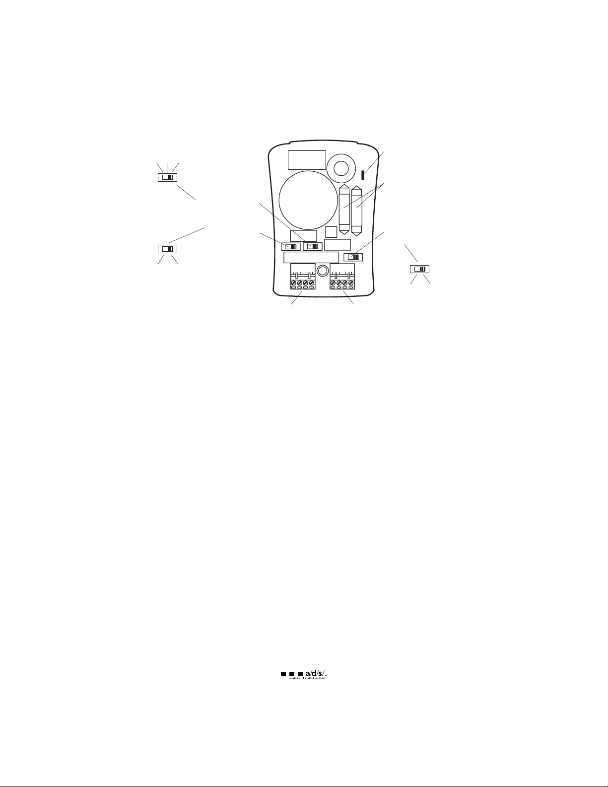
crossover features and connections
Bi-amp/Parallel switch
Select the Bi-amp position if you intend on driving the woofers and tweeters with separate amplifiers (four
channels). Select the Parallel position if you intend on driving the woofers and tweeters with the same
amplifier (two channels).
Tweeter Level switch
The three position switch in the crossover adjusts the output level of the tweeter. The mid-position (0) is
referenced as equal output from the midrange speaker and the tweeter. The high position (+3) provides
3dB more output from the tweeter. The low position (-3) provides 3dB less output from the tweeter. Select
the position of this switch for your listening preference.
Tweeter Phase switch
Selects 0 or 180 degrees phase relationship between the tweeters. Select the position of this switch for
your listening preference.
Tweeter Thermal breaker
This component protects the tweeter if too much power is delivered to the tweeter. If activated, the
tweeter will briefly stop producing sound until the breaker automatically resets.
Tweeter DC Clip protector
These components limit the amount of current delivered to the tweeter if overdriven by either excess
amplification or clipped signal from an overdriven amplifier.
Connections to the amplifier
The crossovers are supplied with removable screw type connectors. The crossovers have two sets of input
terminals, this allows the system to be driven by either two for four channels of amplification. To correctly
use these wiring schemes, you must move the Bi-amp/Parallel switches to the desired position.
To bi-amplify the system you will need 2 stereo amplifiers (or 4 amplifier channels) with one pair of
channels to drive the tweeters and one pair to drive the woofers. In this configuration, the Bi-amp/Parallel
switch must be set to Bi-amp.
-3, 0, +3
4
Tweeter Level (dB)
Switch
Tweeter Thermal
Breaker
Tweeter DC Clip
Protection
Bi-amp–Parallel
Switch
Bi-amp Parallel
IN
Woofer Tweeter
+ - + -
OUT
Woofer Tweeter
+ - + -
Tweeter Phase
Switch
180° 0°

You may also Bi-wire the system by connecting the woofer input terminals to the amplifier and connect
ing the tweeter input terminals to the same amplifier with another set of speaker wires. This is sometimes
done to allow a specific high frequency or low frequency cabling to be used for the two separate signal
paths. See Crossover Installation for additional information on bi-wiring.
Be sure to connect the positive crossover terminals to the positive speaker terminals and positive amplifier
terminals, also ensure that the negative crossover terminals connect to the negative amplifier and speaker
terminals. Once all of the wires are attached to the connector and the crossover is mounted, the
connector can be plugged into its mating receptacle on the crossover.
speaker wiring
Speaker wire selection
Use insulated two-conductor stranded wire to connect the crossover to the speakers and amplifier. The
size of the wire can have an audible effect of the performance of the system. Stranded 18 gauge "zip
cord" will work, but can result in lower output or unpredictable frequency response. For wire runs of 50
feet (15 m) or less, we recommend 16 gauge or larger wire. The crossover connector will accept up to 14
gauge wire.
Polarity and phasing
The polarity of the positive/negative orientation of the connections for every speaker and amplifier
connection must be consistent so all the speakers will be in phase. When the polarity of one connection
is reversed, bass output may be reduced or stereo imaging degraded. Most speaker wire is marked so you
can identify the two conductors. There may be ribs or a stripe on the insulation of one conductor, or the
wire may have clear insulation with different color conductors (copper and silver). There may also be
polarity indications printed on the insulation. Identify the positive and negative conductors and be
consistent with every speaker and amplifier connection. The supplied speaker wire has a white stripe to
indicate the (+) positive conductor.
Termination
The woofer uses an angled locking screw connection integrated to the basket of the speaker. The tweeter
wires are terminated with molded connectors (male and female). Use the supplied wire with insulated
connectors to extend the tweeter wires to the crossover section. Alternatively you may solder the tweeter
wire connections and insulate them with high quality heat shrink tubing.
5
 Loading...