

Page 1
DIGITAL MASS FLOW METER
Design Features
Supports up to 23 Engineering Units (including User Defi ned).
Stores calibration data for up to 10 gases.
Programmable Totalizer indicates total gas quantity.
High and low gas fl ow Alarm limits with preset delay interval.
Two sets of user-programmable electromechanical SPDT relays with latch option.
User-selectable analog 0-5 Vdc or 4-20mA outputs.
Internal Conversion factors for up to 32 gases.
Digital Interface (RS-232 / RS-485, Profi bus DP available).
Multi-Drop Capability of up to 256 units (RS-485 option).
Optional Profi bus DP interface with I&M functionality.
Automatic sensor zero offset adjustment (via digital interface or local push button).
Self-Diagnostic Tests.
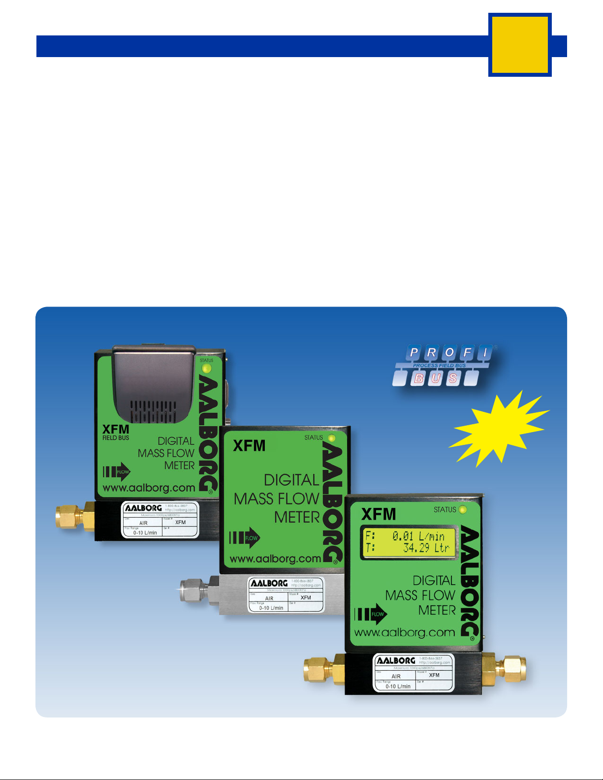
Local 2 x 16 characters LCD display* with adjustable back light (optional).
XFM
XFM with
Profi bus Interface
XFM without
Readout
With I & M
Functionality
XFM with
Readout
Option
XFM Digital Mass Flow Meters
Aluminum and Stainless
Models Shown
* LCD display is not available for Profi bus DP interface option.
BULLETIN 20190620
WWW.AALBORG.COM - E-MAIL 쾷 : INFO@AALBORG.COM - PHONE 845.770.3000 - TOLL FREE IN U.S.A. AND CANADA 1.800.866.3837 ORANGEBURG N.Y. U.S.A.
19
Page 2

DIGITAL MASS FLOW METER
XFM
XFM Digital
Mass Flow Meters
The fl ow rate can be displayed in 23 different volumetric
fl ow or mass fl ow engineering units including user specific. Flow meters can be programmed remotely via RS-232
/RS-485 or optional Profi bus DP interface.
XFM fl ow meters support various functions including: programmable fl ow totalizer, high and low fl ow alarm, automatic zero adjustment, 2 relay outputs, jumper selectable
0-5 Vdc or 4-20 mA analog outputs, status LED diagnostic, capable to store calibration for up to 10 different gases,
internal or user-specifi c K-factors. Optional local 2 x 16
characters LCD display* with adjustable back light provides Flow, Total and diagnostic reading simultaneously.
Principle Of Operation
The stream of gas entering the Mass Flow transducer is
split by shunting a small portion of the fl ow through a capillary stainless steel sensor tube. The remainder of the gas
fl ows through the primary fl ow conduit. The geometry of
the primary conduit and the sensor tube are designed to
ensure laminar fl ow in each branch. According to principles of fl uid dynamics, the fl ow rates of a gas in the two
laminar fl ow conduits are proportional to one another.
Therefore, the fl ow rates measured in the sensor tube are
directly proportional to the total fl ow through the transducer. In order to sense the fl ow in the sensor tube, heat fl ux
is introduced at two sections of the sensor tube by means
of precision-wound heater sensor coils. Heat is transferred
through the thin wall of the sensor tube to the gas fl owing inside. As gas fl ow takes place, heat is carried by the
gas stream from the upstream coil to the downstream coil
windings.
The resultant temperature dependent resistance differential is detected by the electronic control circuit. The measured temperature gradient at the sensor windings is linearly proportional to the instantaneous rate of fl ow taking
place. An output signal is generated that is a function of
the amount of heat carried by the gases to indicate mass
molecular based fl ow rates. Additionally, the XFM model
Mass Flow Meter incorporates a Precision Analog Microcontroller (ARM7TDMI® MCU) and non-volatile memory
that stores all hardware specifi c variables and up to 10
different calibration tables.
* LCD display is not available for Profi bus DP interface option.
Interface
The digital RS485 or RS-232 interface (optional Profi bus DP interface is available) provides access to applicable internal data including: fl ow, CPU temperature,
auto zero, totalizer and alarms settings, gas table,
conversion factors and engineering units selection, dynamic response compensation and linearization table
adjustment. The analog interface provides 0 to 5Vdc or
4 to 20 mA (jumper selectable) outputs for fl ow reading.
Auto Zero
The XFM supports automatic sensor zero offset adjustment which can be activated locally via the maintenance push button or remotely via digital interface. The
auto zero feature necessitates a condition of absolutely
no fl ow through the meter during the adjustment process. Provisions are made to either start, read, or save
the current auto zero value via digital commands.
Totalizer
The total volume of the gas is calculated by integrating
the actual gas fl ow rate as a function of time.
THE DIGITAL INTERFACE COMMANDS ARE PROVIDED TO:
SET THE TOTALIZER TO ZERO.
START THE TOTALIZER AT A PRESET FLOW.
ASSIGN ACTION AT A PRESET TOTAL VOLUME.
START/STOP TOTALIZING THE FLOW.
READ TOTALIZER.
Totalizer conditions become true when the totalizer
reading and the “Stop at Total” volumes are equal. In
addition, the provision is made to automatically disable
Totalizer during sensor warm up period.
Flow Alarm
High and Low gas fl ow ALARM limits can be preprogrammed via digital interface. ALARM conditions become true when the current fl ow reading is equal or
higher/lower than corresponding values of high and low
alarm levels. Alarm action can be assigned with preset
delay interval (0-3600 seconds) to activate the contact
closer (separate for High and Low alarm). Latch Mode
control feature allows each relay to be latched on or
follow the corresponding alarm status.
BULLETIN 20190620
20
WWW.AALBORG.COM - E-MAIL 쾷 : INFO@AALBORG.COM - PHONE 845.770.3000 - TOLL FREE IN U.S.A. AND CANADA 1.800.866.3837 ORANGEBURG N.Y. U.S.A.
Page 3

DIGITAL MASS FLOW METER
TABLE 7 - SPECIFICATIONS
XFM
FLOW MEDIUM:
CALIBRATIONS:
ENVIRONMENTAL (PER IEC 664):
FLOW ACCURACY
REPEATABILITY:
FLOW TEMPERATURE
COEFFICIENT:
FLOW PRESSURE COEFFICIENT:
FLOW RESPONSE TIME:
MAXIMUM GAS PRESSURE:
MAXIMUM PRESSURE DROP:
GAS AND AMBIENT
TEMPERATURE:
RELATIVE GAS HUMIDITY:
LEAK INTEGRITY:
ATTITUDE SENSITIVITY:
OUTPUT SIGNALS:
CONNECTIONS:
TRANSDUCER INPUT POWER:
** FLUID CONTACT:
CAUTION:
Please note that XFM Mass Flow Meters are designed to work only with clean gases.
Never try to measure fl ow rates of liquids with any XFM.
Performed at standard conditions [14.7 psia (101.4 kPa) and 70 °F (21.1 °C)] unless otherwise requested.
Installation Level II; Pollution Degree II.
±1% of FS at calibration temperature and pressure.
±0.15% of full scale.
0.15% of full scale/ °C or better.
0.01% of full scale/psi (6.895 kPa) or better.
600ms time constant; approximately 2 seconds to within ±2% of set fl ow rate for 25% to 100% of full scale fl ow.
500 psig (3447 kPa gauge).
0.18 PSID (at 10 L/min fl ow). 4 psi (at 50 L/min fl ow).
See Table 10 for pressure drops associated with various models and fl ow rates.
32 °F to 122 °F (0 °C to 50 °C). 14 °F to 122 °F (-10 °C to 50 °C) - Dry gases only.
Up to 70%.
-9
smL/sec He maximum to the outside environment.
1 x 10
Deviation of up to 1% from stated accuracy, after re-zeroing.
Linear 0-5 Vdc (3000 ohms min load impedance); Linear 4-20 mA (500 ohms maximum loop resistance).
Maximum noise 20mV peak to peak (for 0-5 Vdc output).
XFM 17 and 37: 1/4" compression fi ttings.
Optional: 6mm compression, 1/4" VCR® , 3/8" or 1/8" compression fi ttings.
XFM 47: 3/8" compression fi ttings.
11 to 26 Vdc, 100 mV maximum peak to peak output noise.
Power consumption: +12Vdc (200 mA maximum); +24Vdc (100 mA maximum);
Circuit board have built-in polarity reversal protection, 300mA resettable fuse provide power input protection.
Aluminum Models: Anodized aluminum, brass, 316 stainless steel, Viton® O-rings.
Stainless Steel Models: 316 stainless steel, Viton
®
Optional O-ring Materials: Buna-N
Aalborg makes no expressed or implied guarantees of corrosion resistance of mass fl ow meters as pertains to
different fl ow media reacting with components of meters. It is the customers’ sole responsibility to select the
model suitable for a particular gas based on the fl uid contacting (wetted) materials offered in the different models.
, EPR® (Ethylene Propylene), or Kalrez® .
®
O-rings.
DISPLAY:
CALIBRATION OPTIONS:
CE COMPLIANCE:
* LCD display is not available for Profi bus DP interface option.
**The selection of materials of construction, is the responsibility of the customer. The company accepts no liability.
BULLETIN 20190620
*Optional local 2x16 characters LCD with adjustable backlight (2 lines of text).
Standard is one 10 points NIST traceable calibration. Optional, up to 9 additional calibrations may be ordered at
additional charge.
EMC Compliance with 89/336/EEC as amended. Emission Standard: EN 55011:1991, Group 1,
Class A Immunity Standard: EN 55082-1:1992.
WWW.AALBORG.COM - E-MAIL 쾷 : INFO@AALBORG.COM - PHONE 845.770.3000 - TOLL FREE IN U.S.A. AND CANADA 1.800.866.3837 ORANGEBURG N.Y. U.S.A.
21
Page 4

DIGITAL MASS FLOW METER
XFM
Multi-Gas Calibration
The XFM is capable of storing primary calibration data for up to 10 gases. This feature allows
the same XFM to be calibrated for multiple
gases while maintaining the rated accuracy on
each.
Conversion Factors
Conversion factors for up to 32 gases are stored
in the XFM. In addition, provision is made for a
user-defi ned conversion factor. Conversion factors may be applied to any of the ten gas calibrations via digital interface commands.
Contact Closure
Two sets of electromechanical SPDT relay
outputs are provided to actuate user-supplied
equipment.
These are programmable via digital interface
such that the relays can be made to switch
when a specifi ed event occurs (e.g. when a low
or high fl ow alarm limit is exceeded or when the
totalizer reaches a specifi ed value) or may be
directly controlled by user.
TABLE 8 - STANDARD FLOW CAPACITIES FOR XFM
XFM 17 XFM 37 XFM 47
mL/min [N
2] L/min [N2] L/min [N2] L/min [N2]
5 1 20 60
10 2 30 80
20 5 40 100
50 10 50
100
200
500
Leak Integrity
1 x 10⁻⁹ smL/sec of Helium maximum to the outside environment.
Engineering Units
The measured gas fl ow and associated totalizer data are scaled
directly in engineering units via the digital interface.
THE FOLLOWING 23 UNITS OF MEASURE ARE SUPPORTED:
TABLE 9 - UNITS OF MEASURE FOR XFM
NUMBER INDEX
1
2
3
4
5
6
7
8
9
10
11
12
13
14
15
16
17
18
19
20
21
22
23
0 % %s Percent of full scale
1 mL/sec mL Milliliter per second
2 mL/min mL Milliliter per minute
3 mL/hr mL Milliliter per hour
4 L/sec Ltr Liter per second
5 L/ min Ltr Liter per minute
6 L/hr Ltr Liter per hour
7 m3/sec m3 Cubic meter per second
8 m3/ min m3 Cubic meter per minute
9 m3/hr m3 Cubic meter per hour
10 ft3/sec f3 Cubic feet per second
11 ft3/min f3 Cubic feet per minute
12 ft3/hr f3 Cubic feet per hour
13 g/sec g Grams per second
14 g/min g Grams per minute
15 g/hr g Grams per hour
16 kg/sec kg Kilograms per second
17 kg/min kg Kilograms per minute
18 kg/hr kg Kilograms per hour
19 Lb/sec Lb Pounds per second
20 Lb/min Lb Pounds per minute
21 Lb/hr Lb Pounds per hour
22 User UD User defi ned
FLOW RATE
ENGINEERING
UNITS
TOTALIZER
ENGINEERING
UNITS
DESCRIPTION
22
TABLE 10 - MAXIMUM PRESSURE DROP FOR XFM
MODEL
XFM 17 up to 10 130 0.18 1.275
XFM 37 up to 50 2722 3.8 26.2
XFM 47 up to 100 1974 11.8 81.4
FLOW RATE
[liters/min]
MAXIMUM PRESSURE DROP
[mm H
2O] [psid] [kPa]
WWW.AALBORG.COM - E-MAIL 쾷 : INFO@AALBORG.COM - PHONE 845.770.3000 - TOLL FREE IN U.S.A. AND CANADA 1.800.866.3837 ORANGEBURG N.Y. U.S.A.
BULLETIN 20190620
Page 5

DIGITAL MASS FLOW METER
XFM
Profi bus Option
TABLE 11 - DIMENSIONS FOR XFM [INCH]
MODEL
XFM 17 1/4" 3.09 5.10 1.00 1.12 4.42 2.81 0.72 4.67 1.42
XFM 37 1/4" 3.57 5.58 1.37 1.37 4.80 2.30 0.70 5.05 1.42
XFM 47 3/8" 3.57 5.68 1.37 1.37 4.80 2.30 0.70 5.05 1.42
*CONNECTION
Compression Fitting
(tube OD)
ABCDEFGH I
TABLE 12 - DIMENSIONS FOR XFM [MM]
*CONNECTION
MODEL
XFM 17 1/4" 78.5 129.5 25.4 28.6 112.3 71.4 18.3 118.6 36.0
XFM 37 1/4" 90.7 141.7 34.9 34.9 121.9 58.4 17.8 128.3 36.0
XFM 47 3/8" 90.7 144.3 34.9 34.9 121.9 58.4 17.8 128.3 36.0
Compression Fitting
(tube OD)
ABCDEFGH I
LCD and NO LCD VERSIONS PROFIBUS CAPABILITY
LCD and NO LCD VERSIONS PROFIBUS CAPABILITY
* For optional fi ttings see table 13.
BULLETIN 20190620
WWW.AALBORG.COM - E-MAIL 쾷 : INFO@AALBORG.COM - PHONE 845.770.3000 - TOLL FREE IN U.S.A. AND CANADA 1.800.866.3837 ORANGEBURG N.Y. U.S.A.
23
Page 6

DIGITAL MASS FLOW METER
XFM
TABLE 13 - XFM ACCESSORIES
CBL-XFM
CBL-DGS
PS-XFM-110NA-2
PS-XFM-110NA-2-A
PS-XFM-230EU-2
PS-XFM-230EU-2-A
PS-XFM-240AU-2
PS-XFM-240AU-2-A
PS-XFM-240UK-2
D-SUB F 15 pins connector with two 6 feet long branches with stripped ends for user supplied power supply and digital
communication interface (no support for analog interface and relays). This cable is included with each instrument.
D-SUB F 15 pins connector with 6 feet long shielded cable (stripped ends).
Can be used with user supplied power supply, allows access to all XFM peripherals. (Optional).
Power Supply / cable assembly 110VAC NA PLUG 12Vdc with 6 feet long communication interface branch stripped ends
(no support for analog interface and relays output). (Optional).
Power Supply / cable assembly 110VAC NA PLUG 12Vdc with 6 feet long communication interface branch stripped ends
with support for analog interface and relays output. (Optional).
Power Supply / cable assembly 230VAC EU PLUG 12Vdc with 6 feet long communication interface branch stripped ends
(no support for analog interface and relays output). (Optional).
Power Supply / cable assembly 230VAC EU PLUG 12Vdc with 6 feet long communication interface branch stripped ends
with support for analog interface and relays output. (Optional).
Power Supply / cable assembly 240VAC AU PLUG 12Vdc with 6 feet long communication interface branch stripped ends
(no support for analog interface and relays output). (Optional).
Power Supply / cable assembly 240VAC AU PLUG 12Vdc with 6 feet long communication interface branch stripped ends
with support for analog interface and relays output. (Optional).
Power Supply / cable assembly 240VAC UK PLUG 12Vdc with 6 feet long communication interface branch stripped ends
(no support for analog interface and relays output). (Optional).
PS-XFM-240UK-2-A
Power Supply / cable assembly 240VAC UK PLUG 12Vdc with 6 feet long communication interface branch stripped
ends with support for analog interface and relays output. (Optional).
BULLETIN 20190620
24
WWW.AALBORG.COM - E-MAIL 쾷 : INFO@AALBORG.COM - PHONE 845.770.3000 - TOLL FREE IN U.S.A. AND CANADA 1.800.866.3837 ORANGEBURG N.Y. U.S.A.
Page 7

XFM MODEL
MAX FLOW (N2)
17 10 L/min
37 50 L/min
47 100 L/min
ORDERING INFORMATION DIGITAL MASS FLOW METER
MATERIAL
A Aluminum
S Stainless Steel
XFM
SEALS
V Viton
B Buna
E EPR
T PTFE / Kalrez
FITTINGS MODEL
A 1/4" Compression XFM 17, 37
B 1/8" Compression XFM 17
C 1/4" VCR
D 3/8" Compression XFM 37, 47
H 6mm Compression XFM 17, 37
®
®
®
DISPLAY
®
XFM 17, 37
N NO Display
L LCD Readout
POWER
6 Universal 11 to 26 Vdc
OUTPUT SIGNAL
A 0-5Vdc
B 4-20mA
DIGITAL INTERFACE
2 RS232
5 RS485
9 PROFIBUS
XFM
17
S
V
A
L
6
A
2
EXAMPLE: XFM17S-VAL6-A2 5 L/min [N2] 20 psig
SPECIFY: Flow Range, Gas and Pressure.
XFM17 stainless steel, Viton® seals, 1/4" compression fi ttings with LCD readout, 11 to 26 Vdc, 0-5 Vdc output signal with RS232 digital interface.
BULLETIN 20190620
WWW.AALBORG.COM - E-MAIL 쾷 : INFO@AALBORG.COM - PHONE 845.770.3000 - TOLL FREE IN U.S.A. AND CANADA 1.800.866.3837 ORANGEBURG N.Y. U.S.A.
*n.a. = not applicable
25
 Loading...