

Page 1

Technical Data Sheet No.: TD-TPU-TPV-11-12 Rev. B Date of Issue: April 2013
OPERATING MANUAL
Aalborg® TPU and TPV Peristaltic Pumps
1
Page 2

®
Aalborg
is a registered trademark of Aalborg Instruments & Controls.
®
Hypalon
Norprene
PharMed
is a registered trademark of DuPont Performance Elastomers, LLC.
®
is a registered trademark of Saint-Gobain Abrasives, Inc.
®
and Tygon® are registered trademarks of Saint-Gobain Performance
Plastics.
NOTE: Aalborg reserves the right to change designs and dimensions at its sole
discretion at any time without notice. For certified dimensions, please contact
®
Aalborg
.
2
Page 3

TABLE OF CONTENTS
1. GENERAL INFORMATION………………………………..4
1.1 General…………………………………………………...4
1.2 Principles of Operation…………………………………..4
1.2.1 TPU Models……………………………………………....5
1.2.2 TPV Models……………………………………………….6
1.2.3 TP1 & TP3 Pump Head Models……………………...…...6
2. UNPACKING THE PUMP………………………………….7
2.1 Inspect Package for Shipping Damage………………….7
2.2 Unpack Your Order……………………………………….7
3. PREPARATION & INSTALLATION……………..………....8
3.1 Installing Tubing in a TPU Pump………………………....8
3.2 Installing Tubing in a TPV Pump………………………....12
3.3 Installing the Pump……………………………………...17
4. SPECIFICATIONS………………………………………....18
5. OPERATING INSTRUCTIONS…………………………….19
5.1 Powering On……………………………………………..19
5.2 Priming the Pump………………………………………..19
5.3 Programming the TPUDP MUR3 Timer (if present)……. 20
5.4 Programming the TPURP MLR1 Timer (if present)….... .23
6. MAINTENANCE…………………………………………...25
7. TROUBLESHOOTING……………………………………..26
8. STORAGE………………………………………………....27
9. RETURN…………………………………………………..28
10. ABBREVIATIONS………………………………………....30
11. WARRANTY……………………………………………....31
3
Page 4

1. GENERAL INFORMATION
1.1 General
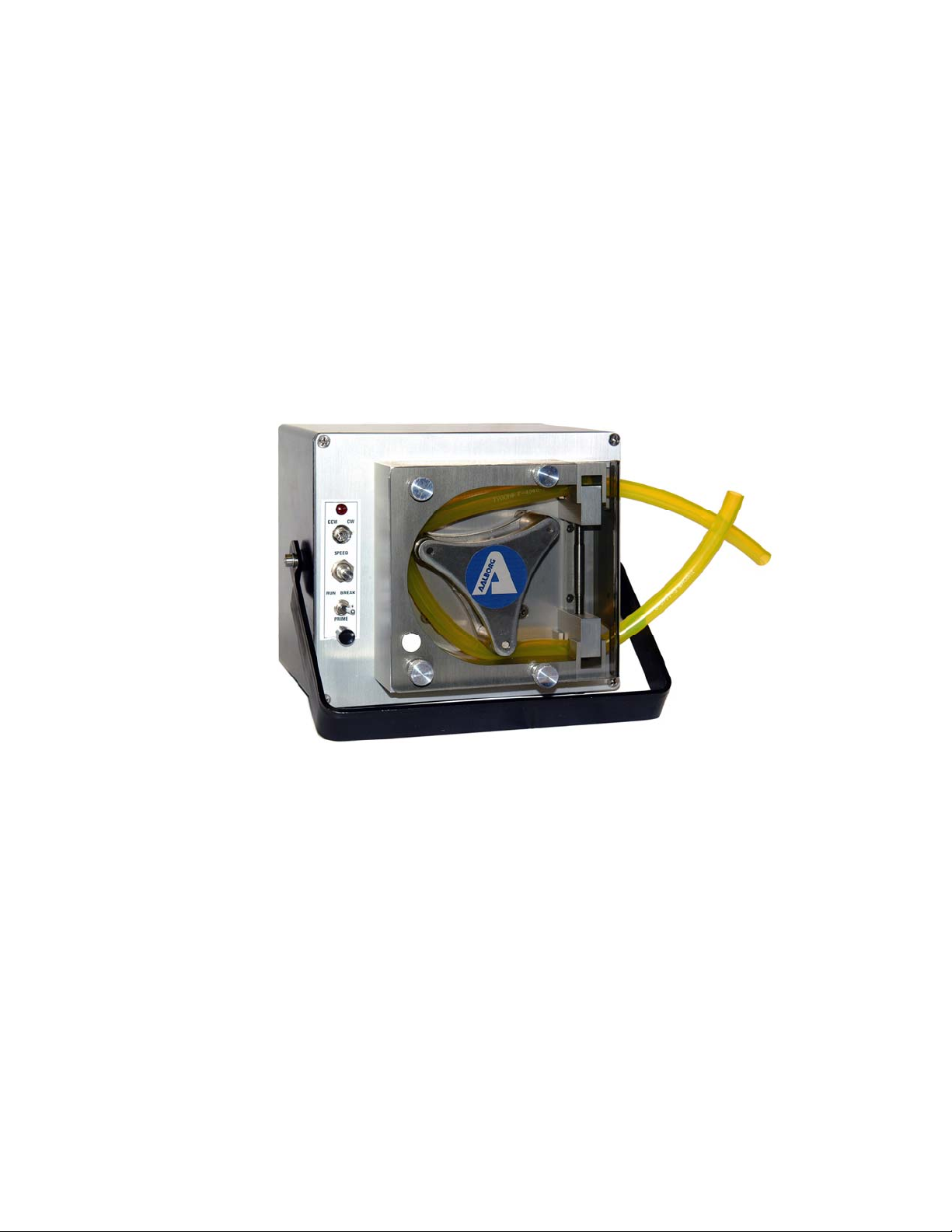
Aalborg’s TPU and TPV model peristaltic pumps are designed
for safety and long life. They are economical, easy to load,
sturdy, and compact for a small footprint. Designed for use
with liquids of widely diverse viscosity, they are suitable for
laboratory, processing and OEM applications, even fuel with
the appropriate tubing.
CAUTION: PERISTALTIC PUMPS, INCLUDING
MODELS TPU AND TPV, ARE NOT SUITABLE FOR USE
WITH BLOOD. THE ROLLER TECHNOLOGY CAN CAUSE
HEMOLYSIS.
1.2 Principles of Operation
Flexible tubing, which conveys fluid from source to
destination, is squeezed inside the pump head by rotating
rollers against a rigid, crescent-shaped occlusion wall. The
rollers induce suction in a pulsing rhythm. The occlusion is
adjustable on TPU models for increased pressure, or
decreased pressure to extend tubing life.
Each pump is comprised of a front panel with controls, a pump
head, a motor, a rigid case with four rubber feet and a handle.
4
Page 5

The handle is practical both to carry the pump and, when
rotated beneath the pump, to serve as a base that lifts and
angles the pump face, making the controls even more easily
accessible to the user.
1.2.1 TPU Models
The TPU models are variable speed or fixed speed pumps. All
versions have 4 rollers standard, with an option of 10 rollers.
The fixed speed TPUFX, powered by an AC motor, is preset
at the factory between 3 and 50 rpm, according to the
customer’s order.
The variable speed TPUAD, TPUDP and TPURP models,
powered by a brushless 24 V DC motor, can be user-set from
0 to 60 rpm. Pumping direction is reversible.
Figure 1: One Model TPU Pump: the TPUAD
5
Page 6
1.2.2 TPV Models
The TPV models, which have a pump head with 3 rollers, are
variable speed pumps, powered by a brushless 24 V DC motor,
can be user-set from 0 to 300 rpm. Pumping direction is
reversible.
Figure 2: One Model TPV Pump: the TPVAD
1.2.3 TP1 & TP2 Pump Head Models
The TP1 and TP2 models are stand alone pump heads with a
safety cover. They are not equipped with control panel, motor
or rigid case. The TP1 model has 4 rollers, while the TP2 model
has 10 rollers.
6
Page 7

2. UNPACKING THE PUMP
2.1 Inspect Package for Shipping Damage
Before you open the cardboard carton that contains your
order, carefully inspect the outside for any external damage
that may have occurred during shipping. If there is any
damage, report it immediately to the shipping company.
2.2 Unpack Your Order
Carefully open the carton from the top. Save all packing
materials for possible reuse for future storage or shipment.
If you find any shipping damage within the box, contact your
shipping company and report the damage to your Aalborg
®
distributor or to Aalborg directly.
Using the packing list, verify that you have received your entire
order. Promptly contact your Aalborg
®
distributor or Aalborg
directly if anything is missing.
7
Page 8
3. PREPARATION & INSTALLATION
3.1 Installing Tubing in a TPU Pump
If you have a TPV pump, skip to Section 3.2.
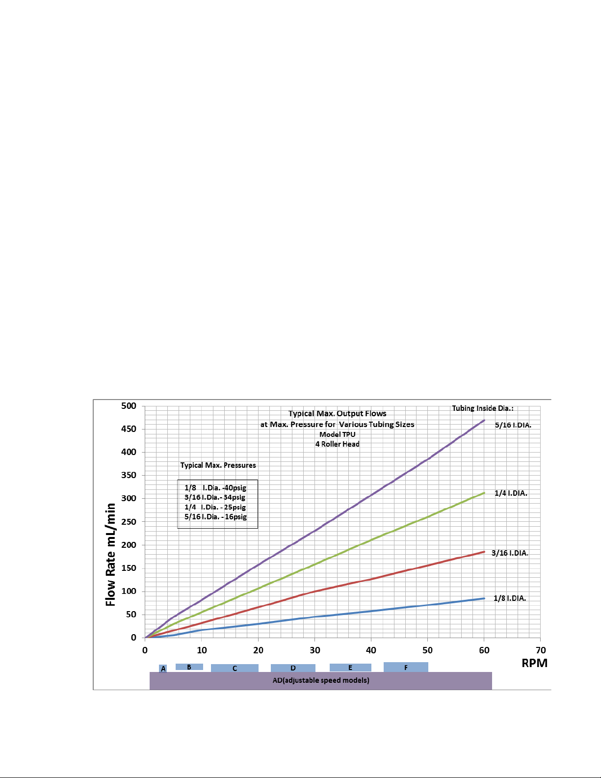
The pumps can take tubing of 1/8-, 3/16-, ¼- and 5/16-inch inner
diameter; all should have a wall thickness of 1/16 inch. Aalborg
recommends the use of the following flexible tubing: Tygon®
3603, peroxide-treated silicone, platinum-treated silicone,
PharMed®, Norprene®, and Hypalon®.
Graphs 1 & 2 provide typical flow rates for TPU pumps with 4
or 10 rollers, using Tygon® laboratory tubing of various inside
diameters:
®
GRAPH 1: TYPICAL TPU PUMP FLOW RATES (with 4 rollers)
8
Page 9
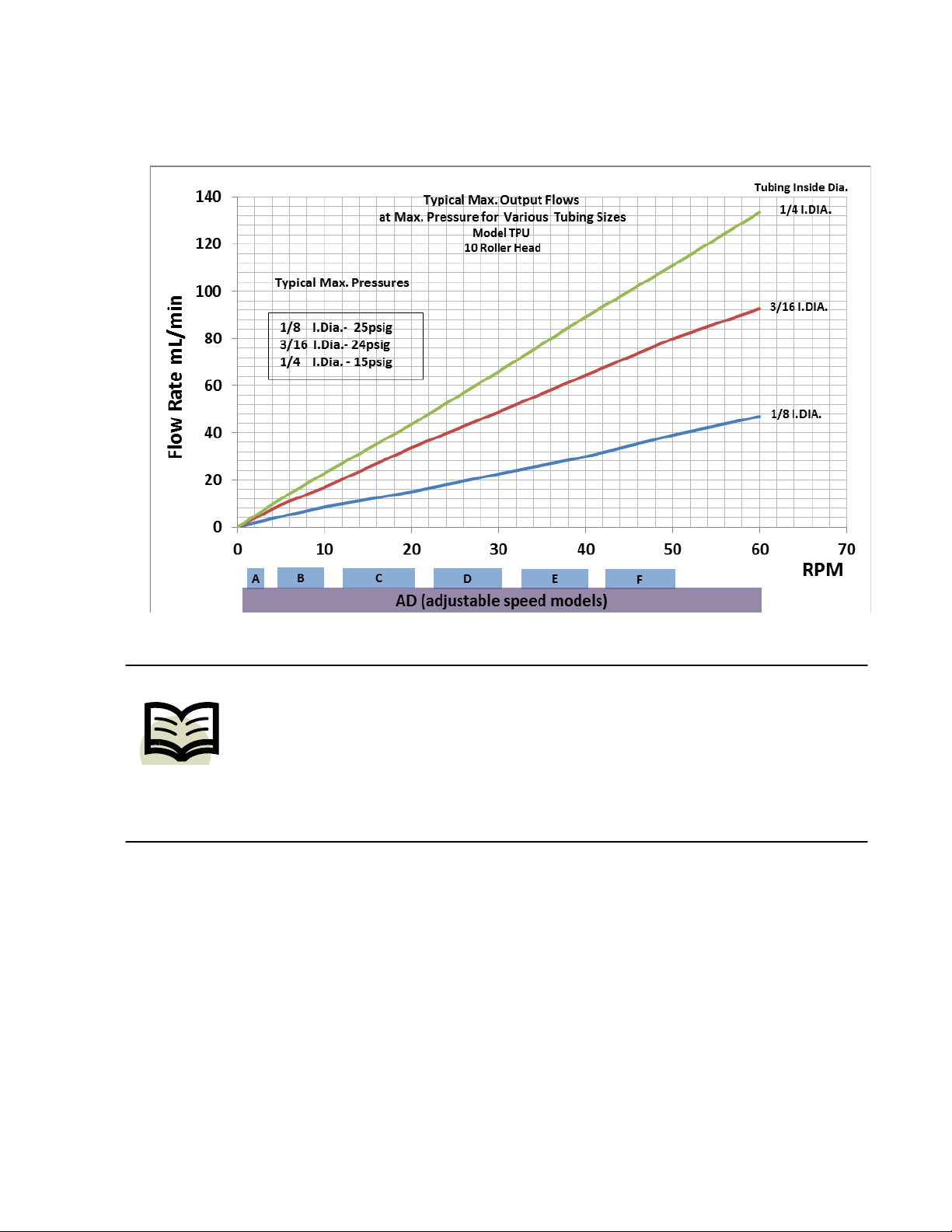
GRAPH 2: TYPICAL TPU PUMP FLOW RATES (with 10 rollers)
NOTE: Not all features are available on all TPU
models. In particular, the speed adjustment knob and
flow direction switch are not available on the fixed
speed models.
Figure 3 calls out the primary user-interface features of a TPU
pump.
9
Page 10
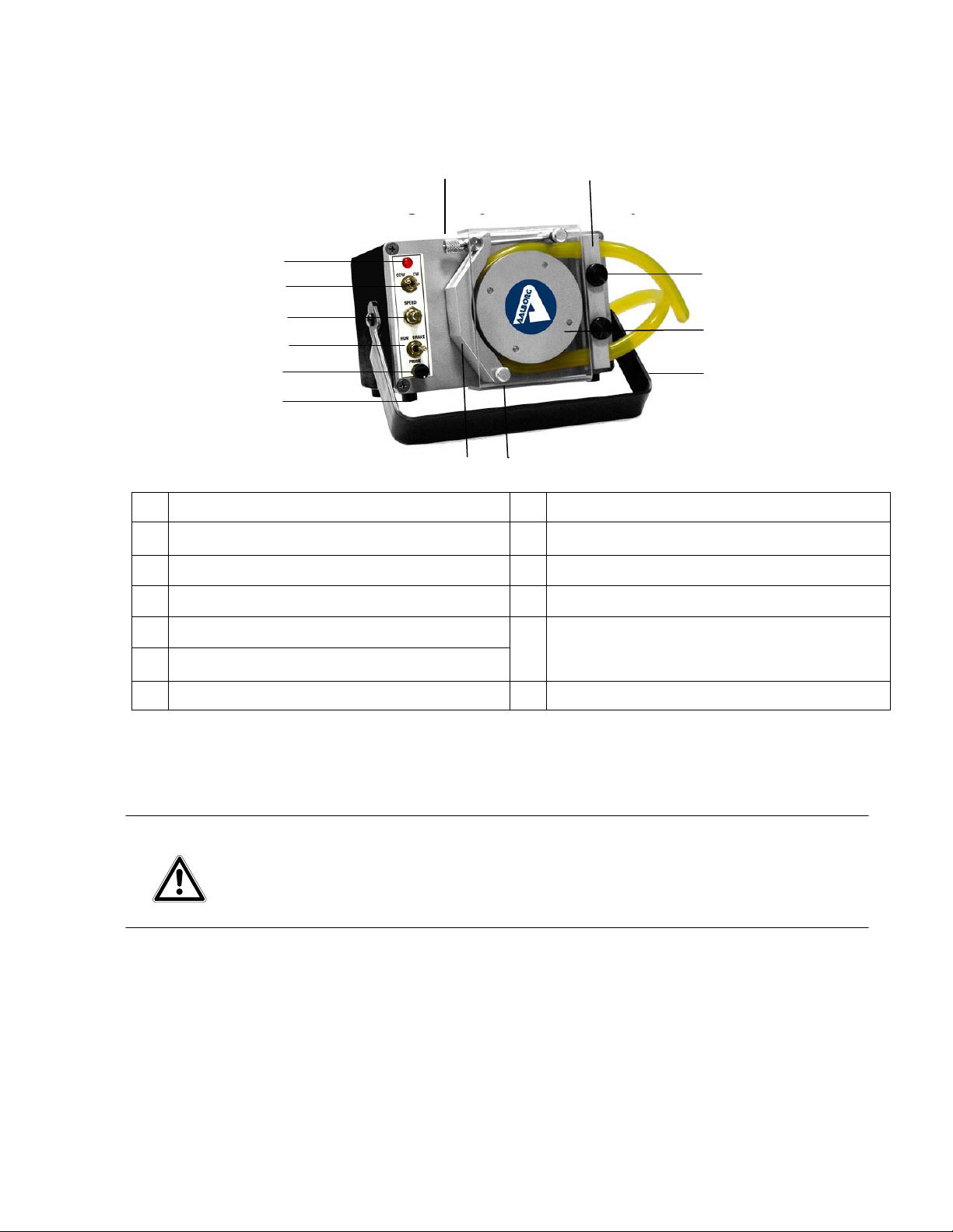
FIGURE 3: TPU PUMP FEATURES (model shown is a TPUAD)
1
2
13
12
11
10
9
8
7
6
3
4
5
1 Occlusion clamp lever 8 Foot (1 of 4)
2 Tubing separator 9 Prime button
3 Thumbscrews for separator 10 Run/Brake (on/off) switch
4 Transparent safety cover 11 Pumping speed adjustment knob
5 Handle/base 12 Flow direction switch (CCW,
6 Cover thumbscrew (1 of 2)
7 Occlusion clamp 13 Run indicator light
counterclockwise/CW, clockwise)
To install tubing, with reference to Figure 3:
CAUTION: MAKE SURE THE PUMP IS TURNED OFF.
BE CAREFUL NOT TO PINCH YOUR FINGERS.
1. Remove the 2 thumbscrews from the transparent safety
cover, then lift the cover away from the pump face and set
it aside.
10
Page 11

2. Unscrew the thumbscrew at the end of the occlusion
clamp lever until the lever is loose enough to move.
3. Move the occlusion clamp lever to release all pressure
from the occlusion clamp, opening the tubing channel.
4. Loosen the 2 black thumbscrews on the tubing separator,
until the separator is free.
5. Lift the separator straight away from the pump face and
set it aside.
6. To load the tubing, lay the tubing in the pump channel
around the pump head, turning the pump head by hand in
either direction, with both ends of the tubing on the
righthand side.
7. When the tubing is in place, reinstall the tubing separator,
with each end cupping the tubing.
8. Finger tighten the black thumbscrews on the tubing
separator until the separator fits snugly against the tubing .
Make sure the tubing is immobilized but not pinched.
9. Snap the occlusion clamp lever back into place and tighten
its thumbscrew until the occlusion clamp is appropriately
tight.
10. Hold the safety cover in place as you reinstall both
thumbscrews. Finger tighten the thumbscrews.
CAUTION: NEVER RUN THE PUMP WITHOUT THE
SAFETY COVER IN PLACE.
11
Page 12

3.2 Installing Tubing in a TPV Pump
The pumps can take tubing of ¼- , 5/16-, 3/8-, 7/16- and ½- inch
inner diameter; all should have a wall thickness of 1/16 inch.
Aalborg
®
recommends the use of the following flexible tubing:
Tygon® 3603, peroxide-treated silicone, platinum-treated
silicone, PharMed
®
, Norprene®, and Hypalon®.
Graphs 3a & 3b provide typical flow rates for TPV pumps with 3
rollers, using Tygon® laboratory tubing of various inside
diameters:
GRAPH 3a: TYPICAL TPV PUMP FLOW RATES
(1/4- , 5/16- & 3/8-inch inner diameter)
12
Page 13

GRAPH 3b: TYPICAL TPV PUMP FLOW RATES
(7/16- & 1/2-inch inner diameter)
13
Page 14

FIGURE 4: TPV PUMP FEATURES
12
11
10
9
8
7
1
2 4
3
5
6
1 Fixed occlusion wall 7 Prime button
2 Pump head (3 rollers) 8 Run/Brake (on/off) switch
3 Cover thumbscrew (1 of 4) 9 Pumping speed adjustment knob
4 Tubing 10 Flow direction switch
5 Adjustable tubing holder
subassembly (see Figure 5)
6 Handle/base 12 Rigid case
11 Run indicator light
One special feature of the TPV pumps is the adjustable tubing
holder subassembly, which functions like a turnbuckle to
loosen the subassembly for removal and to tighten it for
installation. The threading on both ends of its central rod
allows you to independently adjust the pressure of each end
block against the tubing.
14
Page 15

When the subassembly is removed from the pump, each end
block can be spun upward or downward independently on the
turnbuckle. As shown in Figure 5, the end blocks are grooved
on one side. These grooves fit onto the key ridge on the front
plate in order to set the subassembly securely in place.
FIGURE 5: ADJUSTABLE TUBING HOLDER SUBASSEMBLY
2
1
1 End block 2 Turnbuckle
NOTE: Each end block can be raised or lowered
independantly on the rod, to suit the need for the
pressure on the tubing at either ends.
To install tubing, with reference to Figures 4 & 5:
CAUTION: MAKE SURE THE PUMP IS TURNED OFF.
BE CAREFUL NOT TO PINCH YOUR FINGERS.
1
15
Page 16

1. Remove the 4 thumbscrews from the transparent safety
cover, then lift the cover away from the pump face and set
it aside.
2. Loosen the turnbuckle rod between the top and bottom
parts of the tubing holder subassembly, until the
subassembly is movable.
3. Lift the tubing holder straight away from the pump face.
4. To load the tubing, begin to lay the tubing in the pump
channel, with both ends on the righthand side.
5. Manually turn the tri-star shaped head to turn the rollers as
needed so you can insert the tubing against the occlusion
wall.
6. When the tubing is in place, reinstall the tubing holder, with
the cutout on each end cupping the tubing. Make sure to
align the groove in the tubing holder end blocks with the
key ridge on the pump face.
7. Finger tighten the turnbuckle rod between the ends of the
tubing holder until the tubing is securely help in place, top
and bottom.
8. Hold the safety cover in place as you reinstall all 4
thumbscrews. Finger tighten the thumbscrews.
CAUTION: NEVER RUN THE PUMP WITHOUT THE
SAFETY COVER IN PLACE.
16
Page 17

3.3 Installing the Pump
Place the pump on a stable, even surface, and position it so
the pump head and controls are easily accessible to the user.
CAUTION: AFTER THE TUBING IS LOADED BUT
BEFORE THE PUMP IS PRIMED OR RUN, REST THE
PUMP SQUARELY ON ITS 4 RUBBER FEET, TO
PREVENT LIQUID DRIPPING INTO THE PUMP HEAD OR ONTO
THE CONTROLS.
Once the pump has been primed, if desired, you can rotate the
handle underneath the pump to serve as a base. If needed,
tighten the screws that hold the handle to the pump body, so
the handle will not slip from the designated position.
17
Page 18

4. SPECIFICATIONS
TPU
Variable Speed
Rollers, quantity
Material
Maximum Lift,
Pump Head
Maximum
Suction,
Pump Head
Pumping Speeds 0 - 60 rpm Preset to 3, 10, 20,
Motor Brushless DC AC Shaded Pole Brushless DC
Power Supply* Power cord & plug Power cord & plug Power cord & plug
Electrical
Requirement
Fuses Two 2-Amp, 250 V, fast-acting, glass, 5 x 20 mm, UL-listed
4 Standard
10 Optional
316 Stainless steel
340 in H2O
(12.3 psig)
350 in H2O
(12.6 psig)
110-250 V 110-250 V 110-250 V
316 Stainless steel
30, 40 or 50 rpm
TPU
Fixed Speed
4 Standard
10 Optional
340 in H2O
(12.3 psig)
350 in H2O
(12.6 psig)
TPV
Variable Speed
3 Standard
316 Stainless steel
310 in H2O
(11.2 psig)
310 in H2O
(11.2 psig)
0 - 300 rpm
Reversible flow Yes No Yes
Priming function Yes No Yes
Timing function Optional No Optional
*Specific power cords & plugs available for North America, Europe, UK, and
Australia
DIMENSIONS
FX, AD, DP & RP
without handle 6.5 in W x 5.67 in D x 4.12 in H
(16.5 cm W x 14.4 cm D
pump head
alone
6.5 in W x 1.23 in D x 4.12 in H
(16.5 cm W x 3.1 cm D
TPU
x 10.5 cm H)
TPU1
x 10.5 cm H)
TPV
AD, DP & RP
7.7 in W x 7.45 in D x 6.56 in H
(19.6 cm W x 18.9 cm D
x 16.7 cm H)
TPU2
6.5 in W x 1.23 in D x 4.12 in H
(16.5 cm W x 3.1 cm D
x 10.5 cm H)
18
Page 19

5. OPERATING INSTRUCTIONS
5.1 Powering On
1. After you verify that your power cord plug is suitable for
your electrical supply, connect the cord to the back of the
pump case, then plug it into your power outlet.
2. On the back of the pump, turn the on/off power switch ON.
3. If your pump has a Run/Brake switch, turning the switch to
Run will turn the pump on.
5.2 Priming the Pump
With one end of the tubing in the liquid you need to pump, and
the other end in the target receptable or appropriately
clamped to the target site:
If your pump has a Prime button, press and hold the button
at Maximum Speed for a few seconds, until the liquid is
successfully suctioned into the tubing.
If your pump does not have a Prime button, turn the pump
On (main power switch on back). The amount of time it will
take for the pump to prime depends on the preset pump
speed.
19
Page 20

5.3 Programming the TPUDP MUR3 Timer (if present)
The timer relay on this pump model can be set to two modes
of operation, as explained with reference to Figures 6 & 7.
FIGURE 6: LOCATION OF MUR3 TIMER CONTROLS
1
1 See Figure 7 for a closer look
20
Page 21

FIGURE 7: MUR3 TIMER CONTROLS
1
2
3
4
5
1 Start Timer button 4 Multiplication knob
2 Timer ON/OFF switch 5 Relay timer Mode switch
3 Time Period knob
Single Shot Mode
1. Using an appropriate flathead screwdriver, dial the Time
Period (white) knob to the desired position, then dial the
Multiplication (blue) knob to the desired position.
2. To run once for the programmed time period, set the relay
timer MUR3 Mode switch to B.
3. Activate the timed program manually by pressing the
pump’s Start Timer button, or activate it remotely via the
9-pin connector on the pump’s rear panel.
21
Page 22

NOTE: For TPUDP pumps, a Remote Start option is
available using the 9-pin female D-connector located
on the rear panel, via pins 1 and 5.
Continuous Pulse Mode
1. Using an appropriate flathead screwdriver, dial the Time
Period (white) knob to the desired position, then dial the
Multiplication (blue) knob to the desired position.
2. To run a preset continuous program of a specified run time
(ON) followed by the same length of OFF time, set the relay
timer MUR3 Mode switch to Di.
Remember that you can also set the pumping speed, which
will control the amount dispensed during the ON period.
NOTE: Any time you change the TPUDP pump’s MUR3 timer
Mode, the new setting will be activated only after
cycling Timer’s On/Off switch. We recommend
therefore that you change timer Mode settings when
the timer switch set to the Off position. This way, when the
timer On/Off switch set back to the On position, the new
settings will be activated.
22
Page 23

5.4 Programming the TPURP MLR1 Timer (if present)
r
The TPURP timer relay can be set to dispense liquid over a
chosen time period, and to stop dispensing for another chosen
time period. With reference to Figure 8, use the top set of
knobs on the MLR1 timer relay for setting up the dispensing
ON mode, and use the bottom set for setting up the nondispensing OFF mode.
FIGURE 8: MLR1 TIMER CONTROLS
(shown uninstalled)
1
3
4
1 ON Time Period knob 3 OFF Time period knob
2 ON Multiplication knob 4 OFF Multiplication knob
2
The pump can be set to dispense ON and OFF for any of the
following 7 time periods:
1. 0.1 – 1 sec 5. 6 – 60 min
2. 1 – 10 sec 6. 1 – 10 h
3. 6 – 60 sec 7. 10 – 100 hr
4. 1 – 10 min
23
Page 24

Using an appropriate flathead screwdriver, dial the Time
Period (white) knob to the desired position, then dial the
Multiplication (blue) knob to the desired position. For
example, you want your pump to be ON (dispensing) for 24
minutes, and then to be OFF (not dispensing) for 3 hours:
1. Set the top (ON) Time Period knob to the 6 - 60 min range,
then dial the top Multiplication knob t0 the number 4. 6 x 4
= 24 minutes.
2. Set the bottom (OFF) Time Period knob to the 1 - 10 hr
range, then dial the bottom Multiplication knob t0 the
number 3. 1 x 3 = 3 hours .
NOTE: For TPURP pumps. the Start Timer button and
Remote Start option (using the 9-pin female
D-connector located on the rear panel) are not
supported.
24
Page 25

6. MAINTENANCE
Routinely check the tubing for wear and/or leaks. Replace
as needed.
Routinely clean the outside of the pump with a damp cloth,
then wipe it with a dry cloth.
25
Page 26

7. TROUBLESHOOTING
Symptom Possible Solution
Pump does not
power on.
Pump does not
produce the
expected flow.
Make sure the power cord is properly
connected between the back of pump
and the power outlet.
One or both of the fuses needs to be
replaced.
Liquid may have leaked into the pump
head: with the power OFF, clean the
pump head with a moist cloth, then dry
it. If it still does not run, call for service.
Tubing may be loose around the pump
head; remove, then reinstall it tightly.
26
Page 27

8. STORAGE
If you need to store your equipment, we advise you to pack it
for safety in the original shipping carton.
27
Page 28

9. RETURN
If you need to return your pump (or pump component) for
repair, please contact the customer service representative at
your Aalborg
®
distributor or, if you purchased the item
directly, contact the customer service representative at
Aalborg®. Be sure to request a Return Authorization Number
(RAN).
NOTE: Equipment returned without a RAN will not be
accepted.
We advise you to pack the equipment for safety in its original
shipping carton.
You are responsible for return shipping charges. Collect
shipments will be refused.
CAUTION: ANY EQUIPMENT RETURNED FOR
REPAIR MUST BE COMPLETELY CLEANED OF ANY
DANGEROUS MATERIAL, INCLUDING BUT NOT
LIMITED TO TOXIC, BACTERIALLY INFECTIOUS,
CORROSIVE OR RADIOACTIVE SUBSTANCES.
ALL EQUIPMENT RETURNED MUST INCLUDE A FULLY
EXECUTED, SIGNED AND DATED
AVAILABLE FROM YOUR AALBORG® SERVICE MANAGER.
SAFETY CERTIFICATE,
28
Page 29

Aalborg® reserves the right to charge you a fee for equipment
returned under warranty if the instrument is determined to be
free of defects covered by warranty.
29
Page 30

10. ABBREVIATIONS
r
r
The following abbreviations are used in this manual:
AC Alternating Current
cm Centimeters
D Deep
DC Direct Current
H High
Hg Mercury
H2O Water
hr Hours
in Inches
min Minutes
OEM Original Equipment Manufacture
RAN Return Authorization Numbe
rpm Revolutions per minute
sec Seconds
V Volts
W Wide
30
Page 31

11. WARRANTY
Aalborg® TPU and TPV Pumps, Pump Heads & Pump Motors
are warranted against defects in parts and workmanship for
a period of one year from the date of purchase.
If tubing used with is not recommended by Aalborg
®
, this
warranty may be void.
If the instrument is used to pump liquids specifically not
recommended by Aalborg
®
, this warranty may be void.
Defective products will be repaired or replaced solely at the
discretion of Aalborg® at no charge. Shipping charges are
the responsibility of the customer.
This warranty is void if the equipment is found to be
damaged by misuse, accident, or has been repaired or
modified by anyone other than Aalborg
®
or a factoryauthorized service facility.
This warranty defines the obligation of Aalborg® and no
other warranties expressed or implied will be recognized.
NOTE: See Section 9 for proper Return procedures.
31
Page 32

Aalborg
20 Corporate Drive
Orangeburg, New York 10962 USA
Phone: +1 845 770 3000
Fax: +1 845 770 3010
32
 Loading...