

Page 1
OPERATING MANUAL
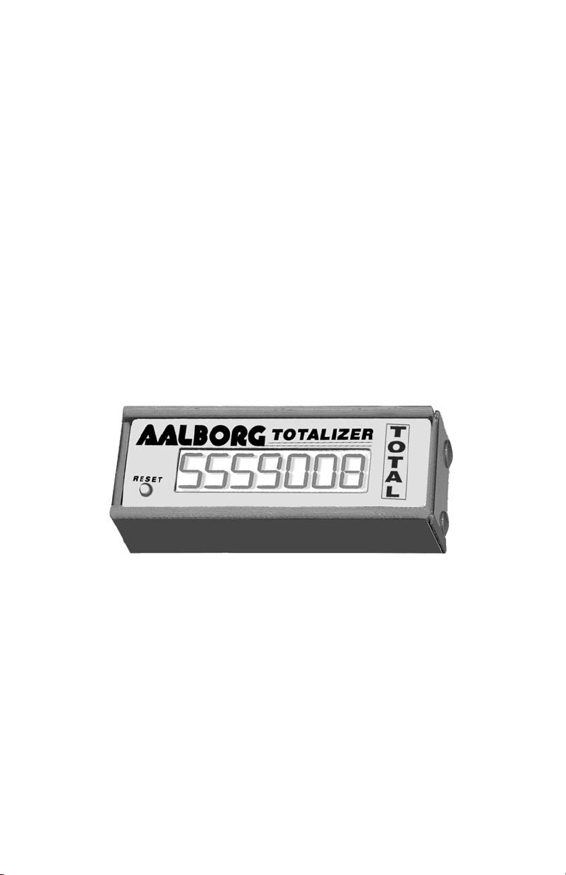
TOTALIZER
Technical Data Sheet No. TD0003 Rev. F
Date of Issue: February 2011
Page 2

Aalborg7 is a registered trademark of Aalborg7 Instruments & Controls.
NOTE: Aalborg7 reserves the right to change designs and dimensions at its sole
discretion at any time without notice. For certified dimensions please contact Aalborg7.
Page 3

TABLE OF CONTENTS
(a) UNPACKING THE TOTALIZER..................................................
a.1 Inspect Package for External Damage..............................................
a.2 Unpack the Totalizer.........................................................................
a.3 Returning Merchandise for Repair....................................................
(b) DESCRIPTION.....................................................................
(c) FEATURES........................................................................
(d) SPECIFICATIONS..................................................................
d.1 General Attributes..............................................................................
d.2 CE Compliance..................................................................................
(e) ELECTRICAL CONNECTIONS...................................................
e.1 Connector Pin Assignments.............................................................
e.2 Jumper Assignments.......................................................................
(f) CALIBRATION PROCEDURES...................................................
f.1 Equipment Required for Calibration....................................................
f.2 Calibration.........................................................................................
f.3 Gain Adjustment..................................................................................
f.4 Re-Scaling of Totalizer.........................................................................
(g) TROUBLESHOOTING GUIDE...................................................
(h) TECHNICAL ASSISTANCE......................................................
APPENDIX 1 GLOSSARY............................................................................
APPENDIX 2 COMPONENT DIAGRAM.....................................................
APPENDIX 3 DIMENSIONS......................................................................
APPENDIX 4 WARRANTY..........................................................................
1
1
1
1
2
2
3
3
3
4
4
4
5
5
5
7
7
9
9
10
11
12
13
Page 4

1
(a) UNPACKING THE TOTALIZER
a.1 Inspect Package for External Damage
Your Totalizer was carefully packed in a sturdy cardboard carton, with antistatic cushioning materials to withstand shipping shock. Upon receipt, inspect
the package for possible external damage. In case of external damage to the
package contact the shipping company immediately.
a.2 Unpack the TOTALIZER
Open the carton carefully from the top and inspect for any sign of concealed
shipping damage. In addition to contacting the shipping carrier please forward a copy of any damage report to your distributor or Aalborg7 directly.
When unpacking the instrument please make sure that you have all the items
indicated on the Packing List. Please report any shortages promptly.
a.3 Returning Merchandise for Repair
Please contact the customer service representative of your distributor or
Aalborg7 if you purchased your Totalizer directly, and request a Return
Authorization Number (RAN). Equipment returned without an RAN will
not be accepted. Aalborg7 reserves the right to charge a fee to the customer
for equipment returned under warranty claims if the instruments are tested to
be free from warranted defects.
Shipping charges are borne by the customer. Items returned "collect" will
not be accepted!
It is mandatory that any equipment returned for servicing be purged and neutralized of any dangerous contents including but not limited to toxic, bacterially infectious, corrosive or radioactive substances. No work shall be performed on a returned product unless the customer submits a fully executed,
signed SAFETY CERTIFICATE. Please request form from the Service
Manager.
Page 5

2
(b) DESCRIPTION
MODEL TOT-10: Totalizer designed to be used with existing models of GFM
mass flow meters and GFC mass flow controllers (calibrated for given flow
rate specified on the back label). It can be connected to the modular jack
instead of the LCD display, or optionally with the additional connector (CBLTOT-10) in parallel with the LCD display. Mechanically TOT-10 can be
installed on the top of the LCD display with two brackets and screws (supplied
only for model TOT-10).
MODEL TOT-05: Totalizer designed to be used with any transducer which has
0 to 5 Vdc output signal and time based engineering units. (i.e. units per second, units per minute, units per hours) It has to be connected to 12 Vdc power
source and 0 to 5Vdc voltage source with additional cable. It is calibrated for
given flow rate specified on the back label.
(c) FEATURES
The Totalizer takes analog output flow signals of 5 to 10 Vdc from the GFM or
the GFC models, or 0 to 5 Vdc from other transducers. It integrates and accumulates up to 7 digits of direct engineering units for the given gas and flow
rate (i.e. standard liters, standard cubic centimeters, etc.). In order to reduce
low signal (noise) totalizing, provision is made for 1% cut off schematic which
allows to accumulate only flow rates which exceeded 1% F. S.
Page 6

3
(d) SPECIFICATIONS
d.1 General Attributes
INPUT ANALOG RANGE: 5 to 10 VDC or 0 to 5 VDC jumper selectable.
POWER SUPPLY REQUIREMENTS:
12Vdc, 100mV Pk-Pk, less than 0.5 watts.
(OPTIONAL, require only for TOT-05).
POWER CONSUMPTION: 10 mA at 12 VDC, less than 0.125 watts.
ACCURACY: ±0.5% of full scale.
TEMPERATURE STABILITY: ±200 ppm/
F
C in the range of 5 FC to 50 FC.
DISPLAY: 7 digit, 8-mm figure height.
READING BACKUP: 20 years lithium battery, no external power required.
RESET: Front panel push button momentary tact switch
(works only when Totalizer is connected to the power).
ALTITUDE: Up to 10,000 feet.
CONNECTION METHOD: Telephone modular plug.
d.2 CE Compliance
Any model Totalizer bearing a CE marking on it, is in compliance with
the below stated test standards currently accepted.
EMC Compliance with 89/336/EEC as amended;
Emission Standard: EN 55011:1991, Group 1, Class B
Immunity Standard: EN 55082-1:1992
Environmental (per IEC 664): Installation Level II; Pollution Degree II
Page 7

4
(e) ELECTRICAL CONNECTIONS
e.1 Connector Pin Assignments
All connections are made at connector J1 (telephone modular plug).
Models TOT-10 can be connected directly to the GFM or GFC. Model TOT-05
have to be connected with optional cable with stripped wires as described
below:
T1 (Yellow) - Analog input 0 to 5Vdc from transducer.
T2 (Green) - 5.0Vdc reference input (used only for TOT-10).
T3 (Black) - 12Vdc Power Supply input.
T4 (Red) - Power supply return (GND), analog input return (Common).
e.2 Jumper Assignments
JP1 - Division factor jumper (has to be installed during calibration,
See Calibration procedure).
Pins [1] and [2] select division 10
Pins [3] and [4] select division 100
Pins [5] and [6] select division 1000
Pins [7] and [8] select division 10000
JP2 - Input mode jumper
Pins [1] and [2] select 0 - 5VDC INPUT mode model TOT-05.
Pins [2] and [3] select 5 - 10 Vdc input mode model TOT-10.
CAUTION: Exceeding the following voltages will cause device
failure and/or hazardous conditions to exist:
TERMINAL NUMBER MAXIMUM VOLTAGE (VDC) MODE
T1 (YELLOW) 16 Voltage Input
T2 (GREEN) 16 Reference Voltage Input
T3 (BLACK) 16 Power Input
CAUTION: Make sure power is OFF when connecting or disconnecting
any cables in the system.
Page 8

5
(f) CALIBRATION PROCEDURE
f.1 Equipment Required for Calibration
You will need:
1. Two 4-1/2" digit Digital Multi Meters set to the selected analog
output range and frequency.
2. For TOT-10: GFM mass flow meter or GFC mass
flow controller with power supply.
3. For TOT-05: Any transducer with 0-5 Vdc output and time
based engineering units and +12Vdc power supply.
f.2 Calibration
Each Totalizer is shipped from the factory with GAIN, OFFSET, SCALE and
DIVISION FACTOR adjustments made for a given flow rate (see Table 2). If
full scale range for Totalizer was not specified on the back label it was by
default adjusted for 30 unit/min which corresponds to SCALE 5.00 kHz and
DIVISION 1000. In this case the Totalizer has to be re-scaled for the desired
full scale range (see f.4). Internal timing schematic GAIN and OFFSET is
adjusted in the factory and does not require additional readjustment when rescaling Totalizer for different flow ranges or engineering units. The GAIN and
OFFSET adjustment procedure (see f.3) must be performed only if the potentiometer R12 (GAIN) was accidentally readjusted.
CAUTION: Improper setting of jumpers may result in incorrect
operation of the unit and could cause damage to the Totalizer.
Page 9

6
TABLE 1
1
If Totalizer has label with
corresponding flow rate on the back
and you do not plan to change the
full scale range.
The Totalizer is ready for use and
does not require any adjustment.
2
If Totalizer has label with
corresponding flow rate on the
back and you do plan to change
the full scale range.
Refer to f.4 RE-SCALING OF
TOTALIZER
3
If Totalizer does not have label
with corresponding flow rate on the
back (default calibration for 30
unit/min) and you do plan to change
the full scale range.
Refer to f.4 RE-SCALING OF
TOTALIZER
4
Use this option only if the
potentiometers R12 (GAIN) or R19
(OFFSET) were accidentally
readjusted.
1. Refer to f.3 and perform
GAIN ADJUSTMENT
2. Refer to f.4 and perform
RE-SCALING OF TOTALIZER for
desired flow range.
Choose from TABLE 1 the option which better matches your case:
Page 10

7
f.3 GAIN Adjustment (required only if potentiometer
R12 GAIN was accidentally readjusted)
1. Carefully remove front panel from the Totalizer.
2. Set potentiometer R8 (SCALE) into completely up position
(CW direction).
3. Connect the Totalizer to the transducer (see e.1).
4. Using a digital multimeter connected to the 0 to 5 Vdc signal at
the output of transducer, set the output rate on the transducer to
full scale (5 Vdc). Connect a second digital multimeter with
selected frequency function (resolution of 4-1/2 digit is required)
to pin [T5] on the Totalizer printed circuit board. Maintain full
scale flow (5000 mV output from transducer) and adjust the
potentiometer R12 (GAIN) for frequency reading of 5.000 kHz
+
10 Hz.
5. Maintain 2% full scale flow (100 mV output from transducer) and
adjust the potentiometer R19 (OFFSET) for frequency reading of
100 Hz
+
2 Hz.
6. Maintain again full scale flow (5000 mV output from transducer)
and adjust the potentiometer R12 (GAIN) for frequency reading
of 5.000 kHz +10 Hz.
f.4 Re-Scaling of Totalizer (if necessary)
It may be desirable to re-scale the Totalizer for different flow ranges or
engineering units.
To change flow range:
1. Calculate the Fs factor which is flow rate specified in UNIT/SEC.
( i.e. standard liters per second [L/sec.], standard cubic
centimeters per second [mL/sec], etc.)
Fs = Fm/60;
where:
Fm = Full scale range in [UNIT/MINUTE] for which your transducer
has been calibrated (usually shown on the front label). If engineering
unit is not minute based it has to be converted. For example 300
SCFH has to be converted to 300/60 = 5 cubic feet/minute.
Page 11

8
2. Choose scale factor Vs and division factor D from Table 2 which
correspond to your previously calculated Fs.
3. Connect the Totalizer to the transducer (see e.1)
4. Carefully remove front panel from the Totalizer. Using the digital
multi meter connected to the 0 to 5 Vdc signal at the output of
transducer, set the flow rate on the transducer to the full scale
flow (5 Vdc). Connect the second digital multimeter with selected
frequency function (resolution of 4 1/2 digit is required) to pin [T5]
on the Totalizer printed circuit board. Maintain full scale
flow and adjust the potentiometer R8 (SCALE) for frequency
reading equal to Vs. For example if you have a transducer with
full scale flow range of Fm = 6 L/Min, your Fs = 6/60 = 0.1 and
from Table 1 the value of Vs = Fs * 10 = 1 kHz.
5. Install jumper JP1 into a position which corresponds to your
division factor D from Table1. For previous example, D = 10000
and the jumper has to be installed for pins [7] and [8] JP1.
TABLE 2
Fm - FULL SCALE RANGE IN [UNIT/MINUTE]
Fm [unit/min] 0.3 to 3.0 3 to 30 30 to 300 30 to 3000 > 3000
Fs [unit/sec.] 0.005 to 0.05 0.05 to 0.5 0.5 to 5.0 5.0 to 50 > 50
Vs [kHz] Scale
Factor
Fs *100 Fs *10 Fs Fs / 10 Fs / 100
D Division
Factor
10000
JP1 7-8
10000
JP1 7-8
1000
JP1 5-6
100
JP1 3-4
10
JP1 1-2
Output
Unit
[unit] [unit] [unit] [unit] [unit]
Page 12

9
(g) TROUBLE SHOOTING
Your Totalizer was thoroughly checked at numerous quality control points during and after manufacturing and assembly operations. It was calibrated in
accordance to conditions for a given.
It was carefully packed to prevent damage during shipment. Should you feel
that the instrument is not functioning properly please check for the following
common conditions first:
Are all cables connected correctly?
Is the power supply correctly selected according to requirements? When several meters are used a power supply with appropriate current rating should
be selected.
Were the connector pinouts matched properly? When interchanging with
other manufacturers equipment, cables and connectors must be carefully
wired for correct.
For best results it is recommended that instruments are returned to the factory for servicing. See section a.3 for return procedures.
(h) TECHNICAL ASSISTANCE
Aalborg7 Instruments will provide technical assistance over the phone to
qualified repair personnel. Please call our Technical Assistance at 845-770-
3000. Please have your Serial Number and Model Number ready when you
call.
CAUTION: Use of the TOTALIZER in a manner other than that
specified in this manual or in writing from Aalborg7, may impair
the protection provided by the equipment.
Page 13

10
APPENDIX 1
GLOSSARY
Fm Full scale range in [UNIT/MINUTE] for which your transducer has
been calibrated (usually shown on the front label). If engineering
unit is not minute based it has to be converted. For example 300
SCFH has to be converted to 300/60 = 5 cubic feet/minute.
Fs Full scale range specified in UNIT/SEC.
Vs SCALE FACTOR in kHz which corresponds output frequency for
given flow rate (see Table 2).
D DIVISION FACTOR corresponds division of the output frequency
for particular flow rate (see Table 2).
Page 14

11
APPENDIX 2
COMPONENT DIAGRAM
R19- OFFSET ADJUSTMENT
R12- GAIN ADJUSTMENT
R8-SCALE ADJUSTMENT
Page 15

12
APPENDIX 3
DIMENSIONS
TOTALIZER
NOTE: Aalborg7 reserves the right to change designs and dimensions at its sole
discretion at any time without notice. For certified dimensions please contact Aalborg7.
Page 16

13
APPENDIX 4
NOTE: Follow Return Procedures in Section a.3.
WARRANTY
Aalborg7 Mass Flow Systems are warranted against parts and
workmanship for a period of one year from the date of purchase.
Calibrations are warranted for up to six months after date of purchase, provided calibration seals have not been tampered with. It is
assumed that equipment selected by the customer is constructed of
materials compatible with gases used. Proper selection is the
responsibility of the customer. It is understood that gases under pressure present inherent hazards to the user and to equipment, and it is
deemed the responsibility of the customer that only operators with
basic knowledge of the equipment and its limitations are permitted to
control and operate the equipment covered by this warranty. Anything
to the contrary will automatically void the liability of Aalborg7 and the
provisions of this warranty. Defective products will be repaired or
replaced solely at the discretion of Aalborg7 at no charge.
Shipping charges
are borne by the customer.
This warranty is void if the equipment is damaged by accident or misuse, or has been repaired or modified by anyone other than Aalborg7
or factory authorized service facility. This warranty defines the obligation of Aalborg7 and no other warranties expressed or implied are
recognized.
 Loading...