

Page 1
OPERATING MANUAL
SMV
Stepping Motor Valve
Technical Data Sheet No. TD0305M Rev. C
Date of Issue: May 2012
Page 2

Aalborg®reserves the right to make changes to information and
specifications in this manual without notice.
Page 3

TABLE OF CONTENTS
1. UNPACKING THE SMV Motorized Valve........................
1.1 Inspect Package for External Damage..................................................
1.2 Unpack the Motorized Valve..................................................................
1.3 Returning Merchandise for Repair........................................................
2. INSTALLATION...............................................................................
2.1 Primary Gas Connections.....................................................................
2.2 Electrical Connections...........................................................................
3. SPECIFICATIONS..........................................................................
3.1 CE Compliance......................................................................................
4. OPERATING INSTRUCTIONS....................................................
4.1 Preparation and Warm Up.....................................................................
4.2 Valve OFF Control (Open Collector NPN Compatible).........................
4.3 Valve Purge/Open.................................................................................
5. TROUBLESHOOTING...................................................................
5.1 Common Conditions..............................................................................
5.2 Troubleshooting Guide...........................................................................
5.3 Technical Assistance.............................................................................
APPENDIX 1 DIMENSIONAL DRAWINGS
APPENDIX 2 WARRANTY
1
1
1
1
2
2
2
4
5
6
6
7
7
8
8
9
9
Page 4

TRADEMARKS
Aalborg®is a registered trademark of Aalborg Instruments.
Buna
®
is a registered trademark of DuPont Dow Elastometers.
Kalrez®is a registered trademark of DuPont Dow Elastomers.
Viton
®
is a registered trademark of Dupont Dow Elastometers L.L.C.
Page 5

1. UNPACKING THE SMV MOTORIZED VALVE
1.1 Inspect Package for External Damage
Your SMV Motorized Valve was carefully packed in a sturdy cardboard car-
ton, with anti-static cushioning materials to withstand shipping shock. Upon
receipt, inspect the package for possible external damage. In case of external
damage to the package contact the shipping company immediately.
1.2 Unpack the Motorized Valve
Open the carton carefully from the top and inspect for any sign of concealed
shipping damage. In addition to contacting the shipping carrier please forward
a copy of any damage report to your distributor or Aalborg
®
directly.
When unpacking the instrument please make sure that you have all the items
indicated on the Packing List. Please report any shortages promptly.
1.3 Returning Merchandise for Repair
Please contact the customer service representative of your distributor or
Aalborg
®
if you purchased your Motorized Valve directly, and request a Return
Authorization Number (RAN). Equipment returned without an RAN will
not be accepted. Aalborg
®
reserves the right to charge a fee to the customer
for equipment returned under warranty claims if the instruments are tested to
be free from warrantied defects.
Shipping charges are borne by the customer. Items returned "collect" will not
be accepted!
It is mandatory that any equipment returned for servicing be purged and neutralized of any dangerous contents including but not limited to toxic, bacterially infectious, corrosive or radioactive substances. No work shall be performed
on a returned product unless the customer submits a fully executed, signed
SAFETY CERTIFICATE. Please request form from the Service Manager.
1
Page 6

2. INSTALLATION
2.1 Primary Gas Connections
Prior to connecting gas lines inspect all parts of the piping system including
ferrules and fittings for dust or other contaminants. Be sure to observe the
direction of gas flow as indicated by the arrow on the front of the meter when
connecting the gas system to be monitored.
Insert tubing into the compression fittings until the ends of the properly sized
tubing home flush against the shoulders of the fittings. Compression fittings
are to be tightened according to the manufacturer's instructions to one and
one quarter turns. Avoid over tightening which will seriously damage fittings.
SMV Motorized Valves are supplied with standard 3/8 inch (SMV-20), 1/2
inch (SMV-30), or 3/4 inch (SMV-40) inlet and outlet compression fittings.
Using a Helium Leak Detector or other equivalent method perform a thorough
leak test of the entire system. (All SMV's are checked prior to shipment for
leakage within stated limits. See specifications in this manual.)
2.2 Electrical Connections
The motorized valve requires a +12VDC power supply with a minimum current rating of 800 mA. Operating power and valve control signals are supplied
via the 9-pin "D" connector located at the side of the valve. For normal operating the motorized valve requires at least two control signals:
l Direction (12V CMOS logic level, pin 8 on the 9-pin "D" connector)
l Speed (0-2.5 VDC analog signal, pin 4 on the 9-pin "D" connector)
When direction is LOW (GND) valve goes down (closes), when direction is
HIGH valve goes up (opens). The "speed" voltage on pin 4 determines how
quickly the valve will operate. The signal amplitude for "speed" control signal
must remain within the limits of 0 to +2.5 VDC.
It may be necessary to override "direction" and "speed" signals with a preset
(2.75 VDC) speed control signal. This can be accomplished with valve CLOSE
and PURGE control signals (open collector NPN compatible). In order to
CLOSE valve pin 3 on the 9-pin "D" connector has to be connected to GND
(pin 2). A GREEN light on the top of the valve will indicate a CLOSE valve
condition. In order to PURGE valve pin 7 on the 9-pin "D" connector has to be
connected to GND (pin 2). A RED light on the top of the valve will indicate a
fully OPEN valve condition.
2
Page 7

During normal operation the valve remains in the last position as it is de-energized. After powering up, the valve will be automatically closed within the first
10 seconds and after that resumes control operation.
FIG.b-1 SMV 9-PIN “D” CONNECTOR CONFIGURATION
WARNING: DO NOT CONNECT 24 Vdc POWER SUPPLY UNLESS YOUR
SMV VALVE WAS ORDERED AND CONFIGURED FOR 24Vdc VOLTAGE
(SEE POWER REQUIREMENTS LABEL). DO NOT APPLY TO THE
DIRECTION CONTROL SIGNAL (PIN 8) VOLTAGE MORE THAN 12 Vdc
Important Notes:
In general, "D" Connector numbering patterns are standardized. There are,
however, some connectors with nonconforming patterns and the numbering
sequence on your mating connector may or may not coincide with the numbering sequence shown in our pin configuration table above. It is imperative
that you match the appropriate wires in accordance with the correct sequence
regardless of the particular numbers displayed on your mating connector.
Make sure power is OFF when connecting or disconnecting any cables in
the system.
The power input is protected by a 1600mA M (medium time-lag) resettable
fuse. If a shorting condition or polarity reversal occurs, the fuse will cut power
to the valve circuit. Disconnect the power to the unit, remove the faulty condition, and reconnect the power. The fuse will reset once the faulty condition
has been removed.
Use of the SMV Motorized Valve in a manner other than that specified in
this manual or in writing from Aalborg
®
, may impair the protection
provided by the equipment.
3
,
PIN FUNCTION
1 (unassigned).
2 Common, Power Supply Minus.
3 Valve Off Control (12V CMOS Low active).
4 Speed control signal (analog 0-2.5 Vdc).
5 (unassigned).
6 Common for Speed control.
7 Valve PURGE control (12V CMOS Low Active).
8 Direction control signal (digital 12Vdc CMOS logic).
9 +12 Vdc (+24Vdc optional) Power Supply Plus.
Page 8

3. SPECIFICATIONS
MATERIALS OF CONSTRUCTION:
ALUMINUM MODELS: Aluminum housings and valve blocks, Viton
®
O-Rings, PFA
closing pins.
STAINLESS/PTFE MODELS: 316 stainless steel valve blocks, PTFE-lined Aluminum
Housing blocks, Viton
®
O-Rings, and PFA closing pins.
MAXIMUM FLOW RATES: 1000 sL/min (air), 28 L/min (water).
CONNECTIONS: 3/8", 1/2", compression and 3/4" FNPT.
ELECTRICAL CONNECTIONS: 9-pin "D" connector, located at the side of the valve.
POWER INPUT: +12Vdc @ 800mA standard or optional +24Vdc @ 600mA. Power
input is protected by 1600mA resetable fuse.
DIRECTIONAL CONTROL SIGNAL: 12Vdc CMOS compatible logic signal (10K input
impedance). UP: Logic High (>7.5Vdc <= 12Vdc). Do not apply more than 12 Vdc.
DOWN: Logic Low (<2.3Vdc).
SPEED CONTROL SIGNAL: Analog 0 to 2.5Vdc (100K input impedance).
TTL ON/OFF OVERRIDE: TTL low level to pins 7 and 3 (10K input impendence).
RESPONSE TIME: 100ms time constant.
DIFFERENTIAL PRESSURES: 700 to 1000 mbars (10 to 15 psid).
MAXIMUM OPERATING PRESSURE: 500 psig (35 bars).
MAXIMUM DIFFERENTIAL PRESSURE: 50 psig (3.45 bars).
ENVIRONMENTAL (PER IEC 664): Installation Level II; Pollution Degree II.
GAS AND AMBIENT TEMPERATURE: 32
F
F to 122 FF (0 FC to 50 FC).
LEAK INTEGRITY: 1 x 10
-7
sccs He max to the outside environment.
WETTED MATERIALS:
SMV20/SMV30/SMV40: Anodized aluminum, brass, and 316 stainless steel with
VITON
®
O-rings seals; BUNA-N®, EPR or KALREZ®O-rings are optional.
4
Page 9

SMV20-S/SMV30-S/SMV40-S: 316 stainless steel with VITON®O-rings seals;
BUNA-N®, EPR or KALREZ®O-rings are optional.
Aalborg
®
makes no expressed or implied guarantees of corrosion resistance
of Motorized Valves as pertains to different flow media reacting with components of valves. It is the customers' sole responsibility to select the model
suitable for a particular gas based on the fluid contacting (wetted) materials
offered in the different models.
3.1 CE Compliance
Any model SMV bearing a CE marking on it, is in compliance with the below
stated test standards currently accepted.
EMC Compliance with 89/336/EEC as amended;
Emission Standard: EN 55011:1991, Group 1, Class B
Immunity Standard: EN 55082 1:1992
5
Page 10

TABLE I FLOW CONFIGURATIONS
4. OPERATING INSTRUCTIONS
The SMV motorized valve requires a +12VDC power supply with a minimum
current rating of 800 mA. The operating power and valve control signals are
supplied via the 9-pin "D" connector located at the side of the valve.
The SMV motorized valve has three modes of operation: Valve Active
(Auto), Valve OFF Control and Valve Purge (Open).
4.1 Valve Active (Auto)
For normal operating in Auto mode the motorized valve requires at least two
control signals:
l Direction (12Vdc CMOS compatible logic level, pin 8 on the 9-pin "D" connector)
l Speed (0-2.5 VDC analog signal, pin 4 on the 9-pin "D" connector)
When direction is LOW (GND) valve goes down (closes), when direction is
HIGH valve goes up (opens). The "speed" voltage on pin 4 determines how
quickly the valve will operate. The signal amplitude for "speed" control signal
must remain within the limits of 0 to +2.5 VDC. The 2.5 Vdc input signal corresponds to approximately 250 steps per second. With resolution of the stepping motor of 0.00025"/step it results in a maximum speed about 0.0625"/sec.
6
MODEL
NUMBERS
CONSTRUCTION
MAXIMUM FLOW RATE
(at 20 psi diff. pressure, 70
F
F)
Cv CONNECTIONS
AIR WATER
sL/min scfh L/min GPM
SMV20-A Aluminum 200 424 5.6 1.48 0.336 3/8”
SMV20-S
316 stainless
steel/PTFE
200
424 5.6 1.48
0.336 3/8”
SMV30-A Aluminum 500 1060 14.2 3.75 0.855 1/2”
SMV30-S
316 stainless
steel/PTFE
500 1060 14.2 3.75
0.855
1/2”
SMV40-A Aluminum 1000 2119 28 7.4 1.735 3/4” FNPT
SMV40-S
316 stainless
steel/PTFE
1000 2119
28 7.4
1.735
3/4” FNPT
Page 11

4.2 Valve OFF Control
(Open Collector NPN Compatible)
It may be necessary or desirable to set the flow and maintain that setting while
being able to turn the flow control valve off and on again. Closing of the valve
(without changing the "speed"and "direction" control signals) can be accomplished by connecting pin 3 of the 9-pin "D" connector to COMMON ( power
ground). The Motorized valve will be given the command to close indicated by
a green light on top of the unit).
Conversely, when the connection is left open or pin 3 remains unconnected
the valve remains active (executes "speed"and "direction" control signals).
The valve will remain active when the VALVE OFF pin remains "floating".
This feature is compatible with open collector NPN transistor switches, as
found in DC output ports of programmable controllers and similar devices.
The simplest means for utilizing the VALVE OFF control feature, is to connect
a toggle switch between the COMMON and VALVE OFF pins of the SMV
valve.
4.3 Valve Purge
At times, it may be necessary to purge the flow system with a neutralizing gas
such as pure dry nitrogen. The SMV valve is capable of a full open condition
for the valve, regardless of setpoint conditions. Connecting the PURGE pin
(pin 7 on 9 pin "D" connector) to ground will fully open the valve.
A red light on top of the valve will indicate an OPEN valve condition, normal
for flow conditions.
Please note that the valve stays OPEN even if power is no longer applied.
To CLOSE the Motorized Control Valve, connect pins 3 and 2.
7
Page 12

5. TROUBLESHOOTING
5.1 Common Conditions
Your SMV motorized valve was thoroughly checked at numerous quality control points during and after manufacturing and assembly operations.
It was carefully packed to prevent damage during shipment. Should you feel
that the instrument is not functioning properly please check for the following
common conditions first:
Are all cables connected correctly?
Are there any leaks in the installation?
Is the power supply correctly selected according to requirements? When several meters are used a power supply with appropriate current rating should be
selected.
Were the connector pinouts matched properly? When interchanging with
other manufacturers' equipment, cables and connectors must be carefully
wired for correct pin configurations.
8
Page 13

5.2 Troubleshooting Guide
For best results it is recommended that instruments are returned to the factory for servicing. See section 1.3 for return procedures.
5.3 Technical Assistance
Aalborg®Instruments will provide technical assistance over the phone to qualified repair personnel. Please call our Technical Assistance at 800-866-3837.
Please have your Serial Number and Model Number ready when you call.
9
INDICATION LIKELY REASON REMEDY
no response to
"speed" and "direction"
control signals
inadequate gas
pressure
apply appropriate gas
pressure
cable or connector
malfunction
check cables and all
connections or replace
valve out of adjustment return to factory for
repair / replacement
valve does not work in
OPEN position
incorrect valve
adjustment
return to factory for
repair / replacement
pc board defect return to factory for
repair / replacement
cable or connectors
malfunction
check cable and
connectors or replace
valve does not work in
CLOSE position
incorrect valve
adjustment
return to factory for
repair / replacement
pc board defect return to factory for
repair / replacement
cable or connectors
malfunction
check cable and
connectors or replace
Page 14

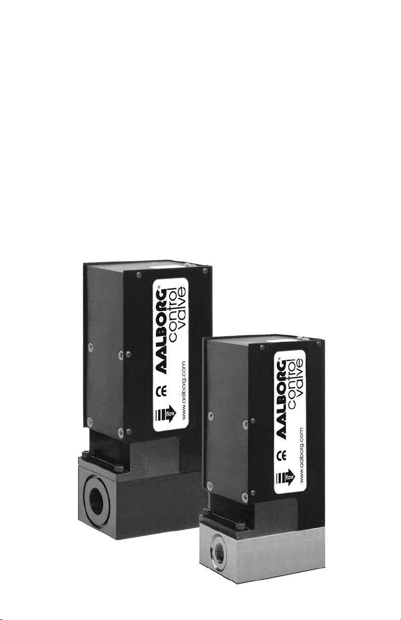
APPENDIX 1
SMV MOTORIZED VALVE
10
6.425"
163 mm
1.125"
29 mm
control valve
3/8"
compression
fitting
depth 2.000
50.8mm
SMV20
3.000
76.2 mm
5.16"
131 mm
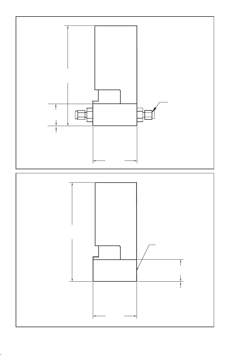
Page 15
11
6.800"
224 mm
1.500"
38.1 mm
depth 2.00
50.8 mm
control valve
1/2"
compression
fittings
6.800"
224 mm
SMV40
3.000
76.2 mm
control valve
3.000
76.2 mm
SMV30
3/4" FNPT
1.500"
38.1 mm
depth 2.000
50.8 mm
Page 16

APPENDIX 2
WARRANTY
NOTE: Follow Return Procedures In Section 1.3.
12
Aalborg®SMV motorized valves are warranted against parts and
workmanship for a period of one year from the date of purchase. It
is assumed that equipment selected by the customer is constructed of materials compatible with gases or liquids used. Proper
selection is the responsibility of the customer. It is understood that
gases under pressure present inherent hazards to the user and to
equipment, and it is deemed the responsibility of the customer that
only operators with basic knowledge of the equipment and its limitations are permitted to control and operate the equipment covered
by this warranty. Anything to the contrary will automatically void the
liability of Aalborg
®
and the provisions of this warranty. Defective
products will be repaired or replaced solely at the discretion of
Aalborg
®
at no charge. Shipping charges are to be borne by the
customer. This warranty is void if the equipment is damaged by
accident or misuse, or has been repaired or modified by anyone
other than Aalborg
®
or factory authorized service facility. This warranty defines the obligation of Aalborg®and no other warranties
expressed or implied are recognized.
CAUTION:
This product is not intended to be used in life support applications!
 Loading...