

Page 1
OPERATING MANUAL
PADDLE WHEEL METER
Technical Data Sheet No. TD-09-117M (temp) Date of Issue: July 2009
aalborg
20 CORPORATE DRIVEORANGEBURG, NY 10962PHONE: 845.770.3000FAX: 845.770.3010
e-mail: info@ aalborg.com
toll free in usa or canada: 1.800.866.3837web site: www.aalborg.com
7
Page 2

CAUTION:
This product is not intended to be used in life support applications!
Page 3

TABLE OF CONTENTS
1. UNPACKING THE PADDLE WHEEL METER...................................
1.1 Inspect Package for External Damage..............................................
1.2 Unpack the Paddle Wheel Meter.......................................................
1.3 Returning Merchandise for Repair.....................................................
2. PWM PADDLE WHEEL METERS................................................
2.1 Principles of Operation.....................................................................
3. SPECIFICATIONS................................................................
4. PARTS............................................................................
5. INSTALLATION...................................................................
6. MAINTENANCE.................................................................
6.1 Sensors..............................................................................................
6.2 Paddle Wheel Disassembly................................................................
7. WARRANTY.........................................................................
1
1
1
1
1
1
2
3
4
4
4
4
5
Page 4

1
1. UNPACKING THE PWM
1.1 Inspect Package for External Damage
Your Paddle Wheel Meter was carefully packed in a sturdy cardboard carton, with antistatic cushioning materials to withstand shipping shock. Upon receipt, inspect the
package for possible external damage. In case of external damage to the package
contact the shipping company immediately.
1.2 Unpack the Paddle Wheel Meter
Open the carton carefully from the top and inspect for any sign of concealed shipping
damage. In addition to contacting the shipping carrier please forward a copy of any
damage report to your distributor or Aalborg
7
directly.
When unpacking the instrument please make sure that you have all the items indicated on the Packing List. Please report any shortages promptly.
1.3 Returning Merchandise for Repair
Please contact the customer service representative of your distributor or Aalborg
7
if
you purchased your Paddle Wheel Meter directly, and request a Return Authorization
Number (RAN). Equipment returned without an RAN will not be accepted.
Aalborg
7
reserves the right to charge a fee to the customer for equipment returned
under warranty claims if the instruments are tested to be free from warrantied defects.
Shipping charges are borne by the customer. Items returned "collect" will not be
accepted!
It is mandatory that any equipment returned for servicing be purged and neutralized of
any dangerous contents including but not limited to toxic, bacterially infectious, corrosive or radioactive substances. No work shall be performed on a returned product
unless the customer submits a fully executed, signed SAFETY CERTIFICATE. Please
request form from the Service Manager.
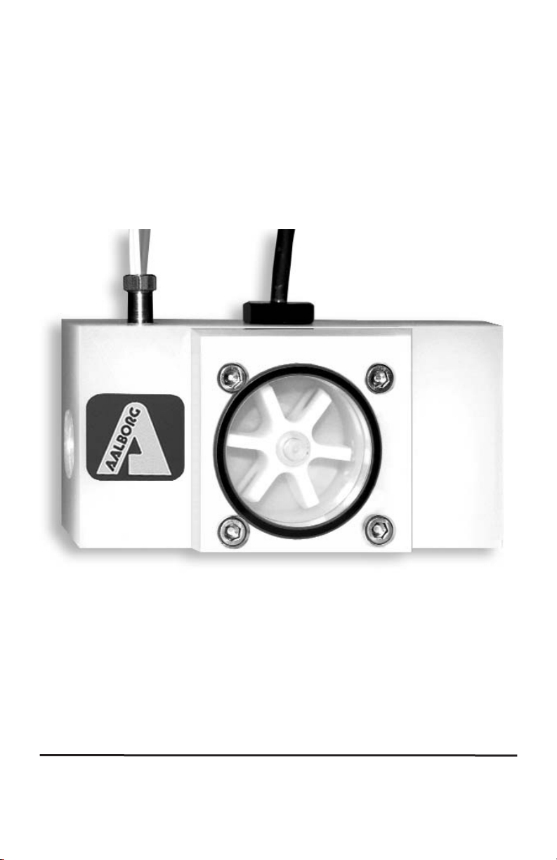
2. PWM PADDLE WHEEL METERS
2.1 Principles of Operation
PWM liquid flow meters consist of a meter body that is installed in-line in a conduit system. Inside, between the inlet and the outlet connections is a rotary wheel with permanent magnets embedded at 180 degrees in paddles.
Fluid flowing through the meter causes the paddle to spin. A magnetic sensor picks up
the frequency of pulses, and the readings are proportional to the liquid flow taking
place. The number of pulses per unit time interval and a K-factor (pulses/unit of flow)
facilitate determining the volumetric rate of flow through the meter.
Page 5

2
SPECIFICATIONS
ACCURACY
±1% FS.
MAX TEMPERATURE
60 °C (140 °F).
MAX PRESSURE
10 bar (150 psi).
POWER
5 to 24 Vdc @ 2 mA.
OUTPUT SIGNAL
NPN open collector (load 30 mA max).
DIMENSIONS
56H x 108L x 53D mm (2.2 x 4.25 x 2.2") Without RTD and flow sensor.
CABLE Flow signal 1.8 m (6') or optional 3.7m (12'). RTD 12 inch long cable.
RTD Platinum 0.00385 TCR, meets EN 60751, Class B.
FLOW RATE FOR PWM
METER
SIZES
FLOW RATE H20
Inlet/Outlet
Ports Female NPT
Max Pressure Drop
[L/min] Gal/min Bar PSI
PWM4 0.15-18.9 0.04-5 3/8" 1 15
PWM6 0.3-37.6 0.08-10 1/2" 1.4 20
PWM8 0.6-64.4 0.15-17 3/4" 1.4 20
PWM10 1.3-132.5 0.35-35 1" 1.4 20
PADDLE WHEEL MODEL NUMBERS
POLYPROPYLENE POLYPROPYLENE with RTD PVDF PVDF with RTD
PWM4P PWM4PR PWM4T PWM4TR
PWM6P PWM6PR PWM6T PWM6TR
PWM8P PWM8PR PWM8T PWM8TR
PWM10P PWM10PR PWM10T PWM10TR
WETTED MATERIALS
POLYPROPYLENE UNITS PVDF UNITS
BODY
Polypropylene PVDF
LID
Acrylic PVDF
PADDLE WHEEL
PVDF PVDF
SHAFT
Nickel Tungsten Carbide Zirconia Ceramic
BEARINGS
Sapphire Jewels Sapphire Jewels
O-RINGS
EPDM PTFE
PLATINUM RTD
316 stainless steel casing 316 stainless steel casing
3. SPECIFICATIONS
Page 6

3
4. PARTS
NOTE: Platinum RTD is not shown.
PARTS LIST
PARTS PWMP MATERIALS PWMT MATERIALS
1
LOWER BLOCK POLYPROPYLENE PVDF
2
JEWEL BEARING (2 required) PVDF SAPPHIRE
3
PADDLE WHEEL
PVDF & NICKEL
TUNGSTEN CARBIDE
PVDF &
ZIRCONIA CERAMIC
4
LID ACRYLIC PVDF
5
SENSOR NOT WETTED PART
6
SCREW 8-32 (4 required) STAINLESS STEEL
7
O-RING EPDM PTFE
8
RTD (Not Shown) STAINLESS STEEL CASING
5
1
2
3
7
2
4
6
Page 7

4
CAUTION: Never use compressed air or gases to test the meter, as this
would damage the Bearings.
5. INSTALLATION
PWM Paddle Wheel Meters are available with or without optional RTD (Resistance
Thermometer Device) probes. NPT female inlet and outlet port sizes are shown in the
table in the flow rate on the preceding page.
It is necessary to include an upstream straight pipe of at least five times the inside
diameter of the line.
Installation horizontally or vertically is acceptable.
The magnetic sensor requires 5-24 VDC power (30 mA max. load).
Flow sensor connection configuration: RED - 5-26 VDC power (+)
BLACK - POWER (-), COMMON
GREEN - SENSOR NPN OPEN COLLECTOR OUTPUT
“pull-up” resistor is necessary for PLC input with current sourcing. Recommended
value: 2.2 K Ohm for 24 VDC input.
PWM meters supplied with (four wire) RTD options are connected using the stainless
steel temperature sensor adapter supplied.
6. MAINTENANCE
6.1 Sensors
In rare instances, due to electrical damage, the pulse sensor needs to be replaced
by unscrewing it and installing a replacement (hand tight).
The RTD /adapter subassembly is replaceable using a wrench.
6.2 Paddle Wheel Disassembly
Bearings are highly susceptible to careless disassembly and reassembly practices.
The nickel Tungsten Shaft of the Wheel is supported at each end by sapphire bearings
to minimize friction and facilitate very low flow rate measurements.
The Wheel may be uninstalled by holding the Lid in place, and removing the four
mounting screws, very carefully to prevent damaging the sapphire Bearings at each
end of the Shaft. If the Bearings are shattered, they need to be replaced.
Reassembly is made ensuring that the Shaft ends are inserted gently into the sapphire
Bearings. Check to see if the wheel is free to spin before the Lid Bearing is installed.
While holding the Lid in place, blow into the meter to verify that the Wheel is free to
spin. Finally the Lid is reinstalled using the four mounting screws.
Page 8

5
WARRANTY
Aalborg7 Paddle Wheels are warranted against parts and workmanship
for a period of one year from the date of purchase. It is assumed that
equipment selected by the customer is constructed of materials compatible with gases used. Proper selection is the responsibility of the customer. It is understood that gases under pressure present inherent hazards to the user and to equipment, and it is deemed the responsibility of
the customer that only operators with basic knowledge of the equipment
and its limitations are permitted to control and operate the equipment
covered by this warranty. Anything to the contrary will automatically void
the liability of Aalborg
7
and the provisions of this warranty. Defective prod-
ucts will be repaired or replaced solely at the discretion of Aalborg
7 at no
charge. Shipping charges are borne by the customer. This warranty is
void if the equipment is damaged by accident or misuse, or has been
repaired or modified by anyone other than Aalborg
7
or factory authorized
service facility. This warranty defines the obligation of Aalborg
7 and no
other warranties expressed or implied are recognized.
The selection of materials of construction, is the responsibility of the customer.
The company accepts no liability.
AALBORG
7 a registered trademark of Aalborg Instruments and Controls, Inc. Aalborg reserves the right to make changes
to information and specifications in this manual without notice. © Copyright 2001 Aalborg Instruments. All rights reserved.
 Loading...