

Page 1
OPERATING MANUAL
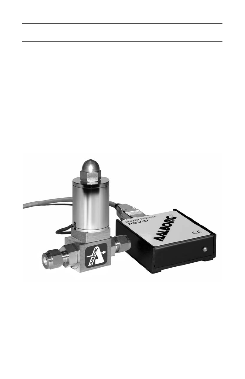
PSV-D
solenoid valve driver
Technical Data Sheet No. TD9610M Rev. E
Date of Issue: March 2011
Page 2

AALBORG7 is a registered trademark of Aalborg Instruments and Controls, Inc.
Aalborg reserves the right to make changes to information and specifications in
this manual without notice.
Page 3

TABLE OF CONTENTS
(a) UNPACKING THE PSV-D DRIVER MODULE......................................
a.1 Inspect Package for External Damage...................................................
a.2 Unpack the Valve Driver Module...........................................................
a.3 Returning Merchandise for Repair.........................................................
(b) INSTALLATION......................................................................
b.1 Electrical Connections...........................................................................
b.1.1 Valve Connection to PSV-D................................................................
b.1.2 Input Reference Signal Connection....................................................
b.1.3 TTL Signal Connection.......................................................................
b.1.4 Power Connection..............................................................................
(c) DESCRIPTION........................................................................
(d) SPECIFICATIONS....................................................................
d.1 CE Compliance......................................................................................
(e) OPERATING INSTRUCTIONS......................................................
e.1 Preparation.............................................................................................
e.2 Maximum Output Voltage to Valve........................................................
e.3 Set Point Reference Signal....................................................................
e.4 TTL, Valve ON/OFF Control....................................................................
(f) TROUBLESHOOTING................................................................
f.1 Common Conditions...............................................................................
f.2 Troubleshooting Guide............................................................................
f.3 Technical Assistance...............................................................................
APPENDIX 1 COMPONENT DIAGRAMS
APPENDIX 2 DIMENSIONAL DRAWINGS
APPENDIX 3 WARRANTY
1
1
1
1
2
2
3
3
3
4
4
4
5
5
5
5
6
6
7
7
7
8
Page 4

(a) UNPACKING THE PSV-D DRIVER MODULE
a.1 Inspect Package for External Damage
Your PSV-D Solenoid Valve Driver Module was carefully packed in a sturdy cardboard carton, with anti static cushioning materials to withstand shipping shock.
Upon receipt, inspect the package for possible external damage. In case of external damage to the package contact the shipping company immediately.
a.2 Unpack the Valve Driver Module
Open the carton carefully from the top and inspect for any sign of concealed shipping damage. In addition to contacting the shipping carrier please forward a copy
of any damage report to your distributor or Aalborg directly.
When unpacking the instrument please make sure that you have all the items
indicated on the Packing List. Please report any shortages promptly.
a.3 Returning Merchandise for Repair
Please contact the customer service representative of your distributor or Aalborg
if you purchased your equipment directly, and request a Return Authorization
Number (RAN). Equipment returned without an RAN will not be accepted.
Aalborg reserves the right to charge a fee to the customer for equipment returned
under warranty claims if the instruments are tested to be free from warranted
defects.
Shipping charges are borne by the customer. Meters returned "collect" will not
be accepted!
It is mandatory that any equipment returned for servicing be purged and neutralized of any dangerous contents including but not limited to toxic, bacterially infectious, corrosive or radioactive substances. No work shall be performed on a
returned product unless the customer submits a fully executed, signed SAFETY
CERTIFICATE. Please request form from the Service Manager.
1
Page 5
(b) INSTALLATION
b.1 Electrical Connections
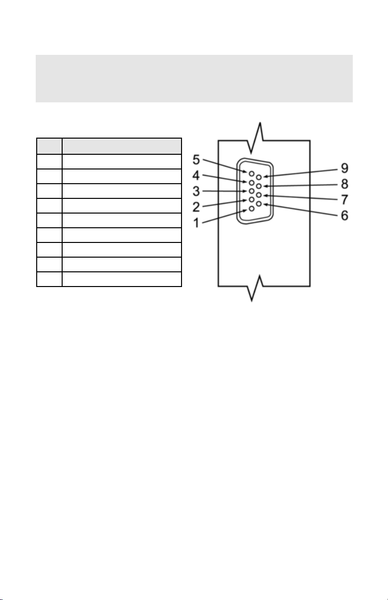
Figure b-1, 9 pin "D" Connector Pinouts for PSV-D Driver Module.
Important notes:
In general, "D" Connector numbering patterns are standardized. There are, however, some connectors with nonconforming patterns and the numbering
sequence on your mating connector may or may not coincide with the numbering
sequence shown in our pin configuration table above. It is imperative that you
match the appropriate wires in accordance with the correct sequence regardless
of the particular numbers displayed on your mating connector.
Make sure power is OFF when connecting or disconnecting any cables in the
system.
The power input is protected by a 1600mA M (medium time lag) resettable fuse.
If a shorting condition or polarity reversal occurs, the fuse will cut power to the
valve driver circuit. Disconnect the power to the unit, remove the faulty condition, and reconnect the power. The fuse will reset once the faulty condition has
been removed.
Use of the PSV-D valve driver in a manner other than that specified in this manual or in writing from Aalborg, may impair the protection provided by the equipment.
PIN FUNCTION
1 Valve, E1
2 Valve, E2
3 Power supply, positive
4 Power supply, common
5 0 to 5 VDC, signal in
6 0 to 5 VDC, common
7 4 to 20 mA, signal in
8 4 to 20 mA, common
9 TTL valve ON/OFF control
2
Caution: It is the users responsibility to determine if the instrument is
appropriate for their OXYGEN application, and for specifying O2 cleaning
service if required. Aalborg is not liable for any damage or personal
injury, whatsoever, resulting from the use of this instrument for oxygen.
Page 6

3
b.1.1 Valve Connection to PSV-D
Connect the two valve solenoid lead wires (E1 and E2) to pins 1 and 2 of the 9
pin "D" connector. There is no polarity on these connections.
b.1.2 Input Reference Signal Connection
Connect the desired analog reference signal input (0 to 5 VDC or 4 to 20 mA) to
the appropriate pin locations on the 9 pin "D" connector of the PSV-D. The PSVD will recognize automatically which signal is being provided. If both are connected, the PSV-D will give priority to the 4 to 20 mA signal when that signal is greater
than 2 mA.
(a) When using the 0 to 5 VDC reference signal, connect the POSITIVE side of the
reference to pin 5, and the NEGATIVE (ground) to pin 6 on the 9 pin "D" connector.
(b) When using the 4 to 20 mA reference signal, connect the POSITIVE side of the
reference to pin 7, and the NEGATIVE (ground) to pin 8 on the 9 pin "D" connector.
For optional RS232 or IEEE488 interfaces please contact your distributor or Aalborg.
b.1.3 TTL Signal Connection
The TTL valve ON/OFF control feature is not required for the device to function.
Use of this SAFETY feature allows for complete de energizing of the solenoid
valve to help ensure valve closure. If this feature is not used, a continuous supply
of nominal power will be supplied to the solenoid valve.
When left unconnected on the 9 pin "D" connector, the device will default to the
"HIGH" setting in accordance with the selected position of the jumper. The factory default setting is LOW (0 VDC) = OFF and HIGH (5 VDC) = ON.
Table I TTL Signal Selection
To reverse this configuration, remove the square cap on the back of the PSV-D
(see figure e-1). The 4th and 5th position determines the TTL logic configuration.
The factory default setting is set with the jumper on position 4. Moving this jumper
to position 5 will yield the reverse configuration [LOW (0 VDC) = ON and HIGH (5
VDC) = OFF] (see Table I).
The NEGATIVE (ground) side of the reference signal inputs is internally
connected on the printed circuit board to power ground.
Jumper Setting (position) TTL LOW (0 VDC) TTL HIGH (5 VDC)
4 OFF ON
5 ON OFF
Page 7

Always make sure that only one jumper is ever applied at any given time to either
position 4 or 5. Connecting both at the same time may result in damage to the
electronics, and improper control.
b.1.4 Power Connection
With the DC power supply source OFF, connect the power to the DC power jack
OR the 9 pin "D" connector.
DO NOT CONNECT POWER TO BOTH CONNECTION POINTS AT
THE SAME TIME. This may result in permanent damage to the power
supplies and the PSV-D.
(c) DESCRIPTION
The PSV-D solenoid driver module is designed to regulate the power supplied to
the proportional solenoid valve (PSV) based on a reference signal. A 0 to 5 VDC
or 4 to 20 mA analog set point signal input is used as a reference to proportionally control the output power to the PSV valve. By increasing or decreasing this
analog reference signal, the PSV valve volume of gases or liquids processed
increases or decreases respectively.
(d) SPECIFICATIONS
Environmental (per IEC 664): Installation Level II; Pollution Degree II.
Connection: 9 pin male "D" connector for input/output signals.
Power Input: +12 to 30 VDC; 1A @ 12 VDC, 0.5A @ 24 VDC via 9 pin "D" connector or DC
power jack (center positive).
Input Signal: AUTO SELECT feature allows circuit to recognize which analog input reference (0 to 5 VDC or 4 to 20 mA) signal is received.
For optional RS232 or IEEE488 interfaces please contact your distributor or Aalborg.
TTL ON/OFF: Jumper selectable LOW (0 VDC) OFF – HIGH (5 VDC) ON [default setting]
or reverse, to select valve ON/OFF status.
Valve Output Power: Jumper selectable to +15, +22, and +29 VDC with adjacent potentiometer to obtain +
2 VDC [default setting 22 VDC].
Fuse Rating: internal resettable 1.6A fuse protects the electronics on the power input.
Polarity Protection: internal rectifier circuit protects from reversed polarity on the power
input.
Operating Temperature: 0
F
C (32 FF) to 50 FF (122 FF).
45
Page 8

d.1 CE Compliance
Any model PSV-D bearing a CE marking on it, is in compliance with the below
stated test standards currently accepted.
EMC Compliance with 89/336/EEC as amended;
Emission Standard: EN 55011:1991, Group 1, Class A
Immunity Standard: EN 55082 2:1995
(e) OPERATING INSTRUCTIONS
e.1 Preparation
It is assumed that the PSV-D has been correctly installed as described in section
(b). Turn the DC power source ON. A pilot light on the front of the PSV-D will illuminate indicating the device is active.
e.2 Maximum Output Voltage to Valve
As shown in Figure e-1, remove the square plug of the PSV-D for the access window. Position 1, 2, and 3 on the header block determine the maximum output voltage supplied to the valve. The factory default setting is 22 VDC (position 2).
Table II Maximum Valve Output Selection
CAUTION: If the valve is left in the active mode for an extended
period of time, it may become warm or even hot to the touch. Use care
in avoiding direct contact with the valve during operation.
Jumper Setting (position) Output Voltage to Valve (VDC)
1 15
2 22
3 29
Page 9

6
The maximum output voltage supplied to the valve, can be set/changed in the
field. Changing this will allow for optimal use of the input reference signal to output valve voltage based on the specific flow rate and operating pressure applied
to the valve.
With the power ON, use Table II and Figure e-1 to make the appropriate changes
as necessary. (Note: This procedure may not need to be performed. It is provided
as an added feature to further customize your system.) Move the jumper to either
position 1, 2, or 3, and use the adjacent potentiometer [P1] to make fine adjustments to the desired output voltage.
Always make sure that only one jumper is ever applied at any given
time to either position 1, 2, or 3. Connecting two or more at the same
time may result in damage to the electronics, and improper control.
e.3 Set Point Reference Signal
The PSV-D solenoid valve driver in conjunction with the PSV solenoid valve allow
the user to set the flow to any desired flow rate within the range of the particular
model installed. The PSV solenoid valve is normally closed when no power is
applied.
The set point input responds to an analog 0 to 5 VDC or 4 to 20 mA reference signal. Use this reference signal via the PSV-D valve driver to set the flow rate of the
PSV solenoid valve.
e.4 TTL, Valve ON/OFF Control
It may, at times, be desirable to set the flow and maintain that setting while being
able to turn the flow control valve off and on again. This can be accomplished by
applying a (TTL compatible) high and low signal of +5 VDC and 0 VDC to pin 9
on the 9 pin "D" connector. The factory default configuration is set so that when 0
VDC (LOW) signal is applied, the solenoid valve is not powered and therefore will
remain normally closed. Conversely, a +5 VDC (HIGH) signal applied will allow the
solenoid valve to remain active. The solenoid valve will remain active when the
VALVE OFF pin remains "floating". (To reverse this configuration, see section
b.1.3)
Toggling the HIGH/LOW signal on and off will allow for activating and deactivating
the solenoid valve. Remember: If the TTL signal line is connected, the valve will
only function if the appropriate logic input is applied.
Page 10

7
INDICATION LIKELY REASON REMEDY
no power to valve
power supply off check connection of power supply
power supply problem
disconnect GFM transducer from
power supply; remove the shorting
condition or check polarities; fuse
resets automatically
pc board defective
check power supply for appropriate
output
no response to
set point
inadequate gas pressure return to factory for replacement
cable or connector malfunction apply appropriate gas pressure
cable or connector malfunction
check cables and all connections or
replace
set point is too low
(<2% of full scale)
re adjust set point
valve adjustment wrong re adjust valve
pc board defective return to factory for replacement
(f) TROUBLESHOOTING
f.1 Common Conditions
Your Solenoid Valve Driver Module was thoroughly checked at numerous quality
control points during and after manufacturing and assembly operations.
It was carefully packed to prevent damage during shipment. Should you feel that
the instrument is not functioning properly please check for the following common conditions first:
Are all cables connected correctly?
Is the power supply correctly selected according to requirements?
Were the connector pinouts matched properly? When interchanging with other
manufacturers' equipment, cables and connectors must be carefully wired for
correct pin configurations.
f.2 Troubleshooting Guide
Page 11

8
INDICATION LIKELY REASON REMEDY
valve does
not work in
“active" position
incorrect valve adjustment re adjust valve
pc board defect return to factory for replacement
cable or connector malfunction
check cable and connectors or
replace
differential pressure too high decrease pressure to correct level
insufficient inlet pressure adjust appropriately
valve does not
work in close
position
incorrect valve adjustment re adjust valve
pc board defect return to factory for replacement
cable or connector malfunction
check cable and connectors or
replace
orifice obstructed
disassemble to remove impediments or return to factory
For best results it is recommended that instruments are returned to the factory
for servicing. See section a.3 for return procedures.
f.3 Technical Assistance
Aalborg Instruments will provide technical assistance over the phone to qualified
repair personnel. Please call our Technical Assistance at 845-770-3000. Please
have your Serial Number and Model Number ready when you call.
Page 12

9
APPENDIX 1
COMPONENTS DIAGRAMS
PSV-D Solenoid Valve Driver PC Board
Page 13

APPENDIX 2
DIMENSIONAL DRAWINGS
PSV-D Solenoid Valve Driver Module
NOTES: Aalborg reserves the right to change designs and dimensions at its
sole discretion at any time without notice. For certified dimensions please contact Aalborg.
10
Page 14

11
APPENDIX 3
NOTE: Follow Return Procedures In Section a.3.
WARRANTY
Aalborg7 Mass Flow Systems are warranted against parts and workmanship
for a period of one year from the date of purchase. Calibrations are warranted for up to six months after date of purchase, provided calibration seals
have not been tampered with. It is assumed that equipment selected by the
customer is constructed of materials compatible with gases used. Proper
selection is the responsibility of the customer. It is understood that gases
under pressure present inherent hazards to the user and to equipment, and
it is deemed the responsibility of the customer that only operators with basic
knowledge of the equipment and its limitations are permitted to control and
operate the equipment covered by this warranty. Anything to the contrary will
automatically void the liability of Aalborg7 and the provisions of this warranty. Defective products will be repaired or replaced solely at the discretion of
Aalborg7 at no charge. Shipping charges are borne by the customer. This
warranty is void if the equipment is damaged by accident or misuse, or has
been repaired or modified by anyone other than Aalborg7 or factory authorized service facility. This warranty defines the obligation of Aalborg7 and no
other warranties expressed or implied are recognized.
Page 15

Page 16

 Loading...