

Page 1
OPERATING MANUAL
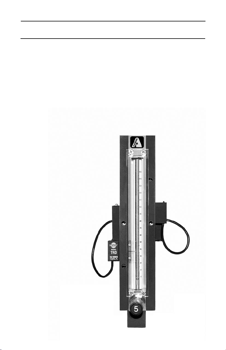
FOR OSS-2
Optical Sensor
Switch
Technical Data Sheet No. TDXXXXM Rev. B
Date of Issue: March 9, 2006
Page 2

TABLE OF CONTENTS
1. UNPACKING the Optical Sensor Switch.......................................
1.1 Inspect Package for External Damage..................................
1.2 Unpack the Optical Sensor Switch........................................
1.3 Returning Merchandise for Repair.........................................
2. DESCRIPTION..................................................................................
3. INSTALLATION.................................................................................
3.1 Electrical Connections............................................................
4. SPECIFICATIONS............................................................................
5. CE Compliance..............................................................................
6. OPERATING INSTRUCTIONS.........................................................
6.1 DIP Switch Configuration........................................................
6.2 Sensor alignment....................................................................
7. TROUBLESHOOTING......................................................................
7.1 Common Conditions...............................................................
7.2 Troubleshooting Guide...........................................................
7.3 Technical Assistance..............................................................
APPENDIX 1 COMPONENT DIAGRAM...............................................
APPENDIX 2 DIMENSIONAL DRAWINGS..........................................
APPENDIX 3 WARRANTY....................................................................
1
1
1
1
1
2
2
4
4
5
5
6
6
6
7
7
8
8
9
Page 3

Aalborg7 is a registered trademark of Aalborg Instruments & Controls.
Aalborg7 reserves the right to make changes to information and specifications
in this manual without notice.
Page 4

1
1 UNPACKING THE Optical Sensor Switch
1.1 Inspect Package for External Damage
Your Optical Sensor Switch was carefully packed in a sturdy cardboard carton,
with anti-static cushioning materials to withstand shipping shock. Upon receipt,
inspect the package for possible external damage. In case of external damage to
the package contact the shipping company immediately.
1.2 Unpack the Optical Sensor Switch
Open the carton carefully from the top and inspect for any sign of concealed shipping damage. In addition to contacting the shipping carrier please forward a copy
of any damage report to your distributor or Aalborg
7 directly.
When unpacking the instrument please make sure that you have all the items
indicated on the Packing List. Please report any shortages promptly.
1.3 Returning Merchandise for Repair
Please contact the customer service representative of your distributor or Aalborg7
if you purchased your Optical Sensor Switch directly, and request a Return
Authorization Number (RAN). Equipment returned without an RAN will not be
accepted. Aalborg7 reserves the right to charge a fee to the customer for equipment returned under warranty claims if the instruments are tested to be free from
warranted defects.
Shipping charges are borne by the customer. Items returned “collect” will not be
accepted!
It is mandatory that any equipment returned for servicing be purged and neutralized of any dangerous contents including but not limited to toxic, bacterially infectious, corrosive or radioactive substances. No work shall be performed on a
returned product unless the customer submits a fully executed, signed SAFETY
CERTIFICATE. Please request form from the Service Manager.
2. DESCRIPTION
The 150mm High /Low Alarm Flow Meter with Optical Sensor Switch is a noninvasive means for detection of a HI or LOW flow. This sensor is ideal for signaling
an alarm, cutoff valve, or other device when the float passes the detector. A small
LED sensor and receiver are mounted on one side of the flow meter. The float
inside the flow tube is detected as it passes across the beam of light. Sensor can
be used to detect float passage beyond the set point of the sensor, or also can be
set to monitor float position at a specific level, signaling when float is outside of
the range of the sensor light beam. Device can be configured to activate relay
and/or audible buzzer alarm.
Page 5

2
3. INSTALLATION
3.1 Electrical Connections
The Optical Sensor Switch requires a +12VDC power supply with a minimum
current rating of 250 mA. Operating power and alarm reset signals are supplied
via the 9-pin AD@ connector located at the side of the Optical Sensor Switch.
Alternatively power can be connected via the DC power jack on the bottom side
of the unit. If you are using your own power supply, be sure that the voltage
level is between +12 and +15 Vdc.
PHONE JACK 2
SUPPLYING DC POWER TO THE POWER JACK AND THE “D” CONNECTOR AT
THE SAME TIME WILL DAMAGE THE METER. DC POWER JACK POLARITY IS
CENTER POSITIVE.
The DIP switch, located near 9-pin D-connector can be used to set up custom
settings separately for High and Low alarm.
9-PIN D-CONNECTOR
ALARM CONFIGURATOR
LED INDICATORS
RESET BUTTON
POWER JACK
PHONE JACK 1
Page 6

3
Important notes:
In general, “D” Connector numbering patterns are standardized. There are, however, some connectors with nonconforming patterns and the numbering
sequence on your mating connector may or may not coincide with the numbering
sequence shown in our pin configuration table above. It is imperative that you
match the appropriate wires in accordance with the correct sequence regardless
of the particular numbers displayed on your mating connector.
Make sure power is OFF when connecting or disconnecting any cables in the
system.
The power input is protected by a 600mA M (medium time-lag) resettable fuse. If
a shorting condition or polarity reversal occurs, the fuse will cut power to the valve
circuit. Disconnect the power to the unit, remove the faulty condition, and reconnect the power. The fuse will reset once the faulty condition has been removed.
Use of the Optical Sensor Switch in a manner other than that specified in this
manual may impair the protection provided by the equipment.
WARNING: DO NOT CONNECT POWER SUPPLY WITH MORE THAN
15Vdc VOLTAGE.
Figure 3.1, Optical Sensor Switch 9 Pin “D” Connector Configuration.
Page 7

4
4. SPECIFICATIONS
MATERIALS OF CONSTRUCTION:
END BLOCKS: Aluminum or 316 Stainless Steel.
ELASTOMERS: Buna7 & Viton7 (Aluminum), Viton7 (316 SS).
FLOW TUBE: Borosilicate glass.
POWER INPUT: 12VDC (15VDC maximum), Recommended Power Supply at
least 250mA regulated, peak to peak max 100mV.
POWER CONSUMPTION: Less than 200mA.
ACCURACY: +/- 2% of full scale.
REPEATABILITY: 0.5% of full scale.
AMBIENT TEMPERATURE: 0-70 deg. C.
RESPONSE TIME: 500 milliseconds.
SOURCE OF LIGHT: 650nm, red LED.
LIGHT IMMUNITY: Pulse modulated.
DRY CONTACT CLOSURES: 2 normally open, and normally closed relays (1A, 30Vdc max.)
ALARM: 70 dB audible buzzer and/or visual LED
ALARM OPTIONS: High, Low, or High/Low.
BUZZER: User configurable, momentary or latch.
RESET: Reset button or remote through “D”-connector, to disable relay
or buzzer (remote Reset is TTL compatible active Low).
Environmental (per IEC 664): Installation Level II; Pollution Degree
AMBIENT TEMPERATURE: 32
F
F to 122 FF (0 FC to 50 FC).
5. CE Compliance
Any model Optical Sensor Switch bearing a CE marking on it, is in compliance
with the below stated test standards currently accepted.
EMC Compliance with 89/336/EEC as amended;
Emission Standard: EN 55011:1991, Group 1, Class B
Immunity Standard: EN 55082 1:1992
Page 8

5
6. OPERATING INSTRUCTIONS
The Optical Sensor Switch requires a +12VDC power supply with a minimum current rating of 250 mA. During initial power up of the Optical Sensor Switch with
no flow conditions the red LED on the retro reflective sensors will be “On”. This is
an indication that power is on and the sensors are ready for operation. When
alarm conditions become “true”, the red LED on the top of the retro reflective sensors goes to “Off”. The retro reflective sensors can be positioned in any position
along the flow meter tube, except directly in front of each other.
6.1 DIP switch configuration
In order to activate the alarm sensors the corresponding switch has to be
installed in the “On” position on the Configuration DIP switch (see Figure 6.1).
Each sensor can be separately set for Momentary or Latch operation. In addition
the Relay and Buzzer can be configured individually. If for example DIP switch
SW1 is set to “On”, when the left retro reflective sensor is active (Alarm
Condition), the relay and green LED (on left side of the D-connector) will be energized in the LATCH mode. They will stay in the energized state without any conditions (even if the flow rate changes and the retro reflective sensor have become
inactive) until the RESET button is pressed or external RESET TTL signal is
applied. If momentary mode is set (DIP switch SW3 is set to “On”) the relay and
green LED will be energized only when the left retro reflective sensor is active
(Alarm Condition). The same is true for Buzzer settings.
All Switches Off – Disable Alarm (LED, Relays and Buzzer).
WARNING: Do not install the sensors closer than 10 mm from one
another. Doing so may trigger a false alarm condition.
ALARM DIP SWITCH CONFIGURATION
LEFT ALARM RIGHT ALARM ACTION WHEN SWITCH IS “ON”
SW1 SW5 LED and Relay are On (LATCH)
SW2 SW6 BUZZER is On (LATCH)
SW3 SW7 LED and Relay are On momentary (FOLLOW SENSOR)
SW4 SW8 BUZZER is On momentary (FOLLOW SENSOR)
Figure 6.1, Optical Sensor DIP Switch Configuration.
Each Optical Sensor Switch is shipped from the factory with the retro-reflective
sensors aligned and does not require additional adjustment of the focus distance.
It may be necessary or desirable to perform realignment of the sensors if the flow
tube was replaced or reinstalled (see p. 6.2).
Page 9

6
6.2 Sensor Alignments
6.2.1 Position the sensor on the side panel of the flow tube until the upper
small alignment screw becomes visible through the service hole on
the side panel.
6.2.2 Using a small 1/16 hex wrench unscrews the alignment screw for
1 – 2 turns in order to release the sensor. Note: Do not completely
remove the alignment screw!
6.2.3 Perform the same procedure (6.2.2) for the second alignment screw
at the opposite side of the side panel.
6.2.4 Position the sensor on the side panel of the flow tube until the bottom
small alignment screw becomes visible through the service hole on
the side panel.
6.2.5 Perform 6.2.2 and 6.2.3 for the bottom alignment screws. This will
release the sensor and will allow positioning it in the horizontal plane
in order to change the focus distance.
6.2.6 Adjust the flow rate through the flow tube until the float will cross the
red LED beam. Find the correct position of the sensor by moving the
sensor in the horizontal plane (toward or against the flow tube) until
the red LED light on the top of the sensor will go off.
6.2.7 Carefully secure the two bottom and two upper alignment screws.
7. TROUBLESHOOTING
7.1 Common Conditions
Your Optical Sensor Switch was thoroughly checked at numerous quality control
points during and after manufacturing and assembly operations. It was carefully
packed to prevent damage during shipment. Should you feel that the instrument
is not functioning properly please check for the following common conditions first:
Are all cables connected correctly?
Are there any leaks in the installation?
Is the power supply correctly selected according to requirements? When several
devices are used a power supply with appropriate current rating should be selected.
Were the connector pinouts matched properly? When interchanging with other
manufacturers' equipment, cables and connectors must be carefully wired for correct pin configurations.
Page 10

7
NO.INDICATION LIKELY REASON SOLUTION
1
No red LED light
on the top of the
Tyne-Eye retro
reflective sensors.
Power supply off. Check connection of the
power supply.
Check cable or connection
from sensor to the Optical
Sensor Switch.
Check cable or connection
from sensor to the Optical
Sensor Switch.
Wrong alignment of the
Tyne-Eye retro reflective
sensor.
Perform alignment procedure
for corresponding Tyne-Eye
retro reflective sensor (see
p.6.2 for detailed instructions).
2
Buzzer or Relay
does not work.
Wrong configuration of the
DIP switch.
Make correct configuration of
the DIP switch according to
Figure 6.1.
Pc board defect. Return to factory for
replacement.
3
The retro
reflective sensor
does not react on
passing float
(the red LED does
not switch to Off).
Wrong alignment of the retro
reflective sensor.
Perform alignment procedure
for the corresponding retro
reflective sensor (see p.6.2 for
detailed instructions).
For best results it is recommended that instruments are returned to the factory for
servicing. See section 1.3 for return procedures.
7.2 Troubleshooting Guide
7.3 Technical Assistance
Aalborg7 Instruments will provide technical assistance over the phone to qualified
repair personnel. Please call our Technical Assistance at 800-866-3837. Please
have your Serial Number and Model Number ready when you call.
Page 11

8
APPENDIX 1
COMPONENTS DIAGRAM
APPENDIX 2
DIMENSIONAL DRAWINGS
2.20
2.01
3.00
2.22
1.00
Page 12

9
APPENDIX 3
NOTE: Follow Return Procedures in Section 1.3.
WARRANTY
Aalborg7 Optical Sensor Switch is warranted against parts and workmanship
for a period of one year from the date of purchase. Calibrations are warranted for up to six months after date of purchase, provided calibration seals have
not been tampered with. It is assumed that equipment selected by the customer is constructed of materials compatible with gases used. Proper selection is the responsibility of the customer. It is understood that gases under
pressure present inherent hazards to the user and to equipment, and it is
deemed the responsibility of the customer that only operators with basic
knowledge of the equipment and its limitations are permitted to control and
operate the equipment covered by this warranty. Anything to the contrary will
automatically void the liability of Aalborg7 and the provisions of this warranty.
Defective products will be repaired or replaced solely at the discretion of
Aalborg7 at no charge. Shipping charges are borne by the customer. This warranty is void if the equipment is damaged by accident or misuse, or has been
repaired or modified by anyone other than Aalborg7 or factory authorized
service facility. This warranty defines the obligation of Aalborg7 and no other
warranties expressed or implied are recognized.
 Loading...