

Page 1
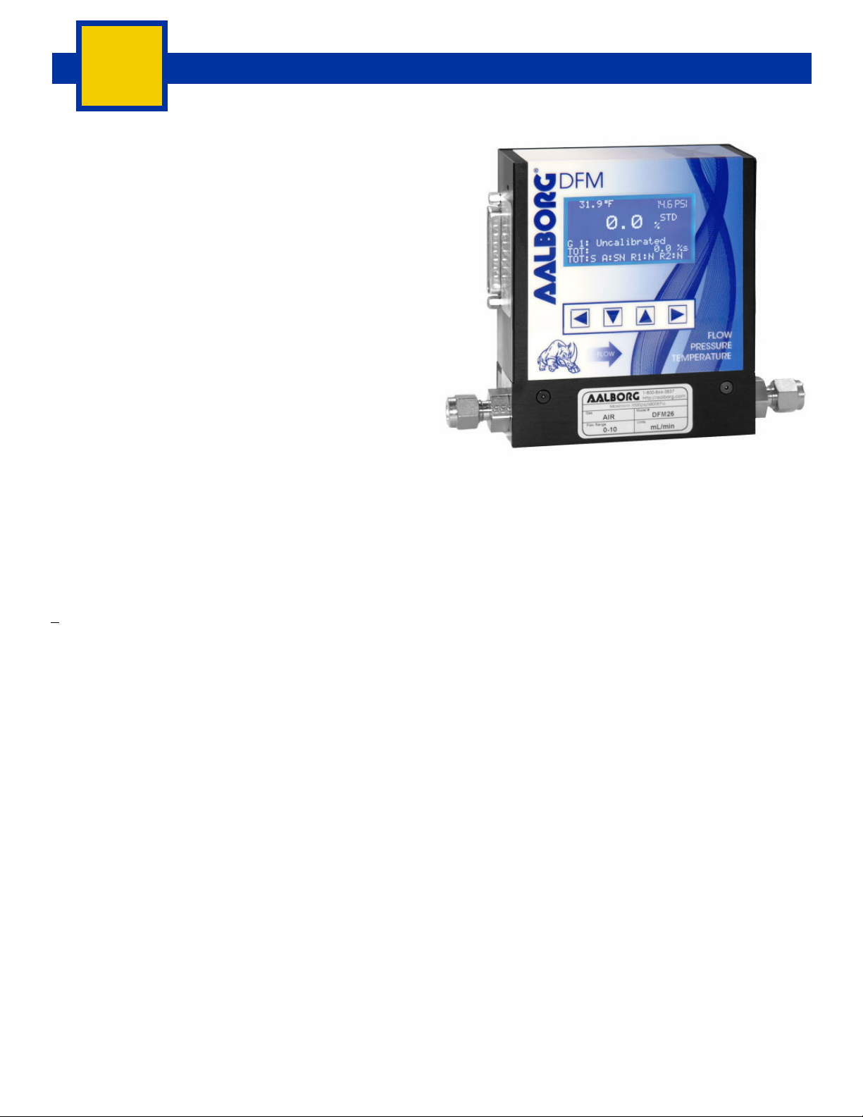
MULTI-PARAMETER DIGITAL MASS FLOW METERS
DFM
Multi-Parameter fl ow meters
provide accurate data
on three different fl uid parameters:
fl ow
pressure
temperature
The fl ow rate can be displayed in volumetric fl ow or
mass fl ow engineering units for standard or actual
(temperature, pressure) conditions. Flow meters can be
programmed locally by the four button keypad and LCD
or remotely via RS-232/RS-485 interface.
DFM fl ow meters support various functions including:
fl ow totalizer, fl ow, temperature, pressure alarms, automatic zero adjustment, 2 relay outputs, 0-5 Vdc / 0-10
Vdc / 4-20 mA analog outputs for fl ow, pressure and
temperature.
DFM’s are offered either as Digital Mass Flow Meters, Model Numbers: DFM26, 36, & 46 or as a Digital
Multi-Parameter Meters, Model Numbers, DFM27, 37 &
47. Model Numbers are displayed in Table 29.
THERE ARE 3 VOLTAGE (POWER) OPTIONS:
+15Vdc, 12Vdc, & 24Vdc.
Interface
All features of the fl ow meter can be accessed via the
local four button keypad and LCD. The digital interface
operates via RS485 (optional RS-232 is available) and
provides access to applicable internal data including:
fl ow, temperature, pressure reading, auto zero, totalizer
and alarms settings, gas table, conversion factors and
engineering units selection, dynamic response compensation and linearization table adjustment. The analog interface provides 0 to 5Vdc or 0 to 10Vdc or 4 to 20
mA outputs for fl ow, pressure and temperature (jumper
selectable).
Auto Zero
The DFM supports automatic sensor zero offset
adjustment which can be activated locally via the keypad or remotely via digital interface. The auto zero
feature requires absolutely no fl ow through the meter
during auto zero process. Provisions are made to either
start, read, or save the current auto zero value via digital commands.
Totalizer
The total volume of the gas is calculated by integrating
the actual gas fl ow rate with respect to time. Both
keypad menu and digital interface commands are
provided to:
Set the totalizer to ZERO.
Start the totalizer at a preset fl ow.
Assign action at a preset total volume.
start/stop totalizing the fl ow.
Read totalizer.
Totalizer conditions become true, when the totalizer
reading and the “Stop at Total” volumes are equal.
Flow Alarm
High and Low gas fl ow ALARM limits can be preprogrammed via keypad or remotely via digital interface.
ALARM conditions become true when the current fl ow
reading is equal or higher/lower than corresponding values of high and low alarm levels. Alarm action can be assigned with preset delay interval (0-3600 seconds) to activate the contact closer (separate for High and Low alarm).
BULLETIN 20190115
62
WWW.AALBORG.COM - E-MAIL 쾷 : INFO@AALBORG.COM - PHONE 845.770.3000 - TOLL FREE IN U.S.A. AND CANADA 1.800.866.3837 ORANGEBURG N.Y. U.S.A.
Page 2
MULTI-PARAMETER DIGITAL MASS FLOW METERS
DFM
Pressure Alarm
High and Low gas pressure ALARM limits can be
preprogrammed via the keypad or remotely via digital
interface. Pressure alarm conditions become true when
the current pressure reading is equal or higher than corresponding values of high pressure alarm settings or
equal or lower than corresponding values of low pressure alarm settings. Alarm action can be assigned to
activate the contact closer (separate for High and Low
pressure alarm).
TABLE 34 - SPECIFICATIONS
ACCURACY:
CALIBRATIONS:
PRESSURE RANGE (MEASUREMENT):
PRESSURE ACCURACY:
TEMPERATURE RANGE (MEASUREMENT):
TEMPERATURE ACCURACY:
REPEATABILITY:
RESPONSE TIME:
TEMPERATURE COEFFICIENT:
PRESSURE COEFFICIENT:
OPTIMUM GAS PRESSURE:
MAXIMUM GAS PRESSURE:
MAXIMUM BURST PRESSURE:
MAXIMUM PRESSURE DROP:
GAS and AMBIENT TEMP:
OUTPUT SIGNALS:
INPUT POWER:
**MATERIALS IN FLUID CONTACT:
CONNECTIONS:
DISPLAY:
CALIBRATION OPTIONS:
CE COMPLIANCE:
ENVIRONMENTAL (PER IEC 664):
±1% of FS at calibration temperature and pressure.
Performed at standard conditions [14.7 psia (101.4 kPa) and 70 °F (21.1°C)] unless otherwise stated.
5 to 100 psia (0.34 to 6.8 bars).
±1% of FS.
32 °F to 122 °F (0 °C to 50 °C).
±1 °C.
±0.25% of full scale.
0.6 to 1.0 second to within ±2% of set fl ow over 20% to 100% of full scale.
0.15% / °C or better.
0.01% of full scale/ 1 psi (0.07 bar) or better.
25 psig (1.73 bars).
DFM 26/36/46: 1000 psig (68 barg, 6895 kPag). DFM 27/37/47: 100 psia (6.8 barabs, 689 kPaabs).
DFM 26/36/46: 1000 psig (68 barg, 6895 kPag). DFM 27/37/47: 200 psig (13.6 barg, 1379 kPag).
See table 36.
32 °F to 122 °F (0 °C to 50 °C). 14 °F to 122 °F (-10 °C to 50 °C) - Dry gases only.
Linear 0-5 Vdc (3000 ohms min load impedance); 0-10Vdc (6000 ohms min impedance);
4-20 mA optional (500 ohms max loop resistance). Maximum noise 20mV peak to peak.
May be confi gured for three different options: ±15Vdc (±200 mA maximum);
+12Vdc (300 mA maximum);
+24Vdc (250 mA maximum);
Circuit boards have built-in polarity reversal protection. Resettable fuses provide power input protection.
316 stainless steel, Viton
Model DFM26/27: Standard 1/4" compression fi ttings.
Optional: 6mm compression fi ttings, 3/8" or 1/8" compression fi ttings and 1/4" VCR
Model DFM36/37: Standard 1/4" compression fi ttings.
Optional: 6mm compression fi ttings, 3/8" compression fi ttings and 1/4" VCR
Model DFM46/47: Standard 3/8" compression fi ttings.
128 x 64 graphic LCD with backlight (up to 8 lines of text).
Standard one 10 points NIST traceable calibration.
Optional up to 9 additional calibrations may be ordered for an additional charge.
EN 55011 class 1, class B; EN50082-1.
Installation Level II; Pollution Degree II.
Temperature Alarm
High and Low gas temperature ALARM limits can be
preprogrammed via the keypad or remotely via digital
interface. Temperature alarm conditions become true
when the current temperature reading is equal or
higher than corresponding values of high temperature
alarm settings or equal or lower than corresponding
values of low temperature alarm settings. Alarm action
can be assigned to activate the contact closer (separate
for High and Low temperature alarm).
®
O-rings. Optional O-rings: Buna®, EPR and Kalrez®.
®
fi ttings.
®
fi ttings.
**The selection of materials of construction, is the responsibility of the customer. The company accepts no liability.
BULLETIN 20190115
WWW.AALBORG.COM - E-MAIL 쾷 : INFO@AALBORG.COM - PHONE 845.770.3000 - TOLL FREE IN U.S.A. AND CANADA 1.800.866.3837 ORANGEBURG N.Y. U.S.A.
63
Page 3

MULTI-PARAMETER DIGITAL MASS FLOW METERS
DFM
Engineering Units
The measured gas fl ow and associated totalizer data
are scaled directly in engineering units via the front
panel keypad or digital interface.
THE FOLLOWING UNITS OF MEASURE ARE SUPPORTED:
%F.S., L/min, L/h, mL/min, mL/h, scuft/h, scuft/min,
lb/h, lb/min, one user defi ned engineering unit.
Multi-Gas Calibration
The DFM is capable of storing primary calibration data
for up to 10 gases. This feature allows the same DFM
to be calibrated for multiple gases while maintaining
the rated accuracy on each.
Conversion Factors
Conversion factors for up to 32 gases are stored in the
DFM. In addition provision is made for a user defi ned
conversion factor. Conversion factors may be applied
to any of the ten gas calibrations via keypad or digital
interface commands.
Contact Closure
Two sets of dry contact relay outputs are provided to
actuate user supplied equipment. These are programmable via the local keypad or digital interface such that
the relays can be made to switch when a specifi ed
event occurs (e.g. when a low or high fl ow, pressure
or temperature alarm limit is exceeded or when the
totalizer reaches a specifi ed value).
TABLE 35 - FLOW RANGES FOR DFM
DFM 26 / 27 LOW FLOW MASS METERS
CODE mL/min [N
01 0 to 10
02 0 to 20
03 0 to 50
04 0 to 100
05 0 to 200
06 0 to 500
CODE L/min [N
07 0 to 1
08 0 to 2
09 0 to 5
10 0 to 10
DFM 36 / 37 MEDIUM FLOW MASS FLOW METERS
CODE L/min [N
11 0 to 15
30 0 to 20
31 0 to 30
32 0 to 40
33 0 to 50
DFM 46 / 47 HIGH FLOW MASS FLOW METERS
CODE L/min [N
40 0 to 60
41 0 to 80
42 0 to 100
2]
2]
2]
2]
Leak Integrity
1 x 10⁻⁹ smL/sec of Helium
maximum to the outside
environment.
64
WWW.AALBORG.COM - E-MAIL 쾷 : INFO@AALBORG.COM - PHONE 845.770.3000 - TOLL FREE IN U.S.A. AND CANADA 1.800.866.3837 ORANGEBURG N.Y. U.S.A.
TABLE 36 - PRESSURE DROP FOR DFM
MODEL
DFM 26 /27
DFM 36 /37
DFM 46 /47
FLOW RATE
[liters/min]
up to 10 25 0.04 0.276
20 300 0.44 3.03
30 800 1.18 8.14
40 1480 2.18 15.03
50 2200 3.23 22.3
60 3100 4.56 31.4
100 5500 8.08 55.7
MAXIMUM PRESSURE DROP FOR DFM
mm H
2O] [psid] [kPa]
BULLETIN 20190115
Page 4

MULTI-PARAMETER DIGITAL MASS FLOW METERS
DFM
Multi-Parameter Mass Flow Meter with Digital Signal Processing
Design Features
Multi-Drop Capability of up to 255 units (for RS-485 option).
Stores calibration data for up to 10 different gases.
Supports 10 different engineering units including user defi ned.
Programmable 12 digits Totalizer indicates total gas volume.
Flow Alarm limits for high and low gas fl ow with relay output.
Pressure Alarm limits for high and low gas pressure with relay output.
Temperature Alarm limits for high & low gas temperature with relay output.
Four button keypad and large 128x64 graphical LCD with back light.
Digital (RS-232 or RS-485) and Analog outputs operate simultaneously.
Internal Conversion factors for up to 32 gases.
Automatic Zero Adjustment.
Self-Diagnostic Tests.
BULLETIN 20190115
WWW.AALBORG.COM - E-MAIL 쾷 : INFO@AALBORG.COM - PHONE 845.770.3000 - TOLL FREE IN U.S.A. AND CANADA 1.800.866.3837 ORANGEBURG N.Y. U.S.A.
65
Page 5

MULTI-PARAMETER DIGITAL MASS FLOW METERS
DFM
25-PIN D-CONNECTOR MALE
5.00 [127.0]
0.50 [12.7]
0.63 [15.9]
1.63 [41.3]
25-PIN
D-CONNECTOR MALE
5.25 [133.4]
0.53 [13.5]
4.25 [108.0]
6.27 [159.3]
6-32-2B 0.15 DEEP
0.28 [7.1]
0.69 [17.5]
2.69 [68.3]
66
0.50 [12.7]
5.25 [133.4]
0.63 [15.9]
2.00 [50.8]
DFM36 and DFM37
7.27 [184.6]
7.49 [190.2]
*
6-32-2B 0.15 DEEP
0.32 [8.3]
0.69 [17.5]
DFM46 and DFM47
FOR HIGH FLOW MASS FLOW METER
*
0.80 [20.3]
WWW.AALBORG.COM - E-MAIL 쾷 : INFO@AALBORG.COM - PHONE 845.770.3000 - TOLL FREE IN U.S.A. AND CANADA 1.800.866.3837 ORANGEBURG N.Y. U.S.A.
2.69 [68.3]
BULLETIN 20190115
Page 6

ORDERING INFORMATION MULTI-PARAMETER DIGITAL MASS FLOW METERS
DFM MODEL
MAX. FLOW (N2)
26 10 L/min
36 50 L/min
46 100 L/min
27 10 L/min
37 50 L/min
47 100 L/min
MATERIAL
S Stainless Steel
DFM
SEALS
V Viton
B Buna
E EPR
T PTFE / Kalrez
FITTINGS MODEL
A 1/4" Compression DFM 26, 27, 36, 37
B 1/8" Compression DFM 26 & 27
C 1/4" VCR
D 3/8" Compression DFM 26, 27, 36, 37, 46, 47
H 6mm Compression DFM 26, 27, 36, 37
®
®
DISPLAY
®
®
DFM 26, 27, 3, 37
L LCD readout
POWER
2 12 Vdc
4 24 Vdc
5 +15 Vdc
OUTPUT SIGNAL
A 0-5 Vdc
B 4-20 mA
C 0-10 Vdc
TEMP & PRESSURE OUTPUT
SIGNAL (A only 26, 36, 46)
TEMP OUT PRESSURE OUT
CODE
A n.a. n.a.
B 0-5Vdc 0-5Vdc
C 0-5Vdc 4-20mA
D 0-5Vdc 0-10Vdc
E 4-20mA 0-5Vdc
F 4-20mA 4-20mA
G 4-20mA 0-10Vdc
H 0-10Vdc 0-5Vdc
I 0-10Vdc 4-20mA
J 0-10Vdc 0-10Vdc
*n.a. = not applicable.
**DIGITAL INTERFACE
2 RS232
5 RS485
**RS485 is
standard. No cost
optional RS232 is
selected by
changing the last
digit of part
number from 5 to 2.
DFM
36
S
V
A
L
5
A
A
EXAMPLE: DFM36S-VAL5-AA5 50 L/min [N2] 20 psig
SPECIFY: Flow Range, Gas and Pressure.
DFM36 stainless steel, Viton® seals, 1/4" compression fi ttings, LCD readout display, ±15 Vdc power, 0-5Vdc output signal, RS485 digital interface.
BULLETIN 20190115
WWW.AALBORG.COM - E-MAIL 쾷 : INFO@AALBORG.COM - PHONE 845.770.3000 - TOLL FREE IN U.S.A. AND CANADA 1.800.866.3837 ORANGEBURG N.Y. U.S.A.
5
67
 Loading...