

Page 1
MASS FLOW METERS
GFM
Design Features
Rigid metallic construction.
Maximum pressure of 1000 psig (70 bars).
Leak integrity 1 x 10⁻⁹ of helium.
NIST traceable certifi cation.
Built-in tiltable LCD readout.
0-5 Vdc and 4-20 mA signals.
Circuit protection.
Can be used as a portable device.
Engineering units or 0 to 100% displays.
TIO Totalizer option.
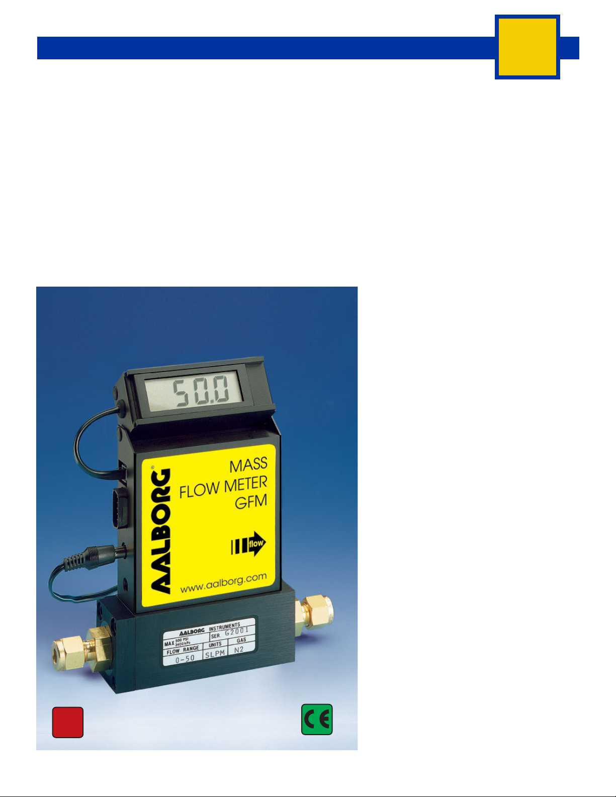
Typical Aluminum GFM Mass Flow Meter
Principles of Operation
Metered gases are divided into two laminar
fl ow paths, one through the primary fl ow conduit, and the other through a capillary sensor
tube. Both fl ow conduits are designed to ensure laminar fl ows and therefore the ratio of
their fl ow rates is constant.
Two precision temperature sensing windings
on the sensor tube are heated, and when
fl ow takes place, gas carries heat from the
upstream to the downstream windings. The
resultant temperature differential is proportional to the change in resistance of the sensor windings.
A Wheatstone bridge design is used to monitor the temperature dependent resistance
gradient on the sensor windings which is linearly proportional to the instantaneous rate
of fl ow.
Output signals of 0 to 5Vdc and 4 to 20mA
are generated indicating mass molecular
based fl ow rates of the metered gas.
Flow rates are unaffected by temperature
and pressure variations within stated limitations.
General Description
Compact, self-contained GFM mass fl ow
meters are designed to read fl ow rates of
gases. The rugged design coupled with instrumentation grade accuracy provides versatile and economical means of fl ow measurement.
Aluminum or stainless steel models with
readout options of either engineering units
(standard) or 0 to 100 percent displays are
available.
The mechanical layout of the design includes
an LCD readout built into the top of the transducer. This readout module is tiltable over 90
NIST
Traceable
Calibration
BULLETIN 20190620
WWW.AALBORG.COM - E-MAIL 쾷 : INFO@AALBORG.COM - PHONE 845.770.3000 - TOLL FREE IN U.S.A. AND CANADA 1.800.866.3837 ORANGEBURG N.Y. U.S.A.
degrees to provide optimal reading comfort. It
is connected to the transducer by a standard
modular plug, and is also readily removable
for remote reading installations.
13
Page 2

MASS FLOW METERS
GFM
NIST
Traceable
Calibration
GFM 57, 67 and 77
High Flow Mass Flow Meters
TABLE 1 - SPECIFICATIONS FOR GFM
ACCURACY:
CALIBRATIONS:
REPEATABILITY:
RESPONSE TIME:
TEMPERATURE COEFFICIENT:
PRESSURE COEFFICIENT:
MAXIMUM PRESSURE DROP:
GAS AND AMBIENT TEMP.:
OUTPUT SIGNALS:
TRANSDUCER INPUT POWER:
TIME CONSTANT:
GAS PRESSURE:
** MATERIALS IN
FLUID CONTACT:
ATTITUDE SENSITIVITY:
CONNECTIONS:
LEAK INTEGRITY:
CE COMPLIANT:
GFM 17, 37 and 47: ±1.0% of full scale.
GFM 57, 67 and 77: ±1.5% of full scale. OPTIONAL ENHANCED ACCURACY: ±1.0% of full scale.
Performed at standard conditions [14.7 psia (101.4 kPa) and 70 °F (21.1 °C)] unless otherwise requested.
±0.25% of full scale.
Generally 2 seconds to within ±2% of actual fl ow rate over 25 to 100% of full scale.
0.15% of full scale / °C.
0.01% of full scale / psi (0.07 bar).
See Table 3.
32 °F to 122 °F (0 °C to 50 °C). 14 °F to 122 °F (-10 °C to 50 °C) - Dry gases only.
Linear 0-5 Vdc. 1000 ohms min. load impedance and 4-20 mA 0-500 Ohms loop resistance.
Universal +12 to +26 Vdc, 200 mA maximum.
800 ms.
1000 psig (70 bars) maximum GFM 17, 37, 47. 20 psig (1.4 bars) optimum.
500 psig (34.5 bars) GFM 57, 67, 77. 20 psig (1.4 bars) optimum.
a. Aluminum models GFM Series: anodized aluminum, 316 stainless steel, brass and Viton
b. Stainless steel models GFM17S, 37S,47S, 57S, 67S and 77S: 316 stainless steel and Viton
Optional O-rings: Buna® , EPR and Kalrez® .
No greater than +15 degree rotation from horizontal to vertical; standard calibration is in horizontal position.
GFM 17: 1/4" compression fi ttings. Optional: 6mm, 3/8" and 1/8" compression fi ttings or 1/4" VCR
GFM 37: 1/4" compression fi ttings. Optional: 6mm and 3/8" compression fi ttings or 1/4" VCR
GFM 47: 3/8" compression fi ttings.
GFM 57: 3/8" compression fi ttings.
GFM 67: 1/2" compression fi ttings.
GFM 77: 3/4" FNPT fi ttings or 3/4" compression fi ttings.
-9
1 x 10
EN 55011 class 1, class B; EN50082-1.
smL/sec of helium maximum to the outside environment.
®
O-rings.
®
O-rings.
®
.
®
.
BULLETIN 20190620
** The selection of materials of construction, is the responsibility of the customer. The company accepts no liability.
14
WWW.AALBORG.COM - E-MAIL 쾷 : INFO@AALBORG.COM - PHONE 845.770.3000 - TOLL FREE IN U.S.A. AND CANADA 1.800.866.3837 ORANGEBURG N.Y. U.S.A.
Page 3

MASS FLOW METERS
GFM
Transducers without LCD readout are offered for
Leak Integrity
OEM applications.
1 x 10⁻⁹ smL/sec of helium max to outside environment.
GFM mass fl ow meters are available with fl ow
ranges from 10 mL/min to 1000 L/min N
2. Gas-
TABLE 3 - MAXIMUM PRESSURE DROP FOR GFM
es are connected by means of 1/4" ,3/8" ,1/2"
compression fi ttings and 3/4" FNPT fi ttings. Optional fi ttings are available. These meters may be
used as bench top units or mounted by means of
screws in the base.
Transducer power supply ports are fuse and polarity protected.
TABLE 2 - FLOW RANGES FOR GFM
GFM 17 LOW FLOW MASS FLOW METERS
CODE mL/min [N
01
02
03
04
05
06
CODE L/min [N
07
08
09
10
11
30
31
32
33
40
41
42
50
60
70
BULLETIN 20190620
0 to 100
0 to 200
0 to 500
GFM 37 MEDIUM FLOW MASS FLOW METERS
GFM 47 HIGH FLOW MASS FLOW METERS
0 to 100
GFM 57 HIGH FLOW MASS FLOW METERS
0 to 200
GFM 67 HIGH FLOW MASS FLOW METERS
0 to 500
GFM 77 HIGH FLOW MASS FLOW METERS
0 to 1000
2]
0 to 10
0 to 20
0 to 50
2]
0 to 1
0 to 2
0 to 5
0 to 10
0 to 15
0 to 20
0 to 30
0 to 40
0 to 50
0 to 60
0 to 80
MODEL
GFM 17
GFM 37
GFM 47
GFM 57
GFM 67
GFM 77
TABLE 4 - ACCESSORIES FOR GFM
POWER SUPPLY - BATTERY PACK - CABLES
PS-GFM-110NA-2
PS-GFM-110NA-4
PS-GFM-230EU-2
PS-GFM-230EU-4
PS-GFM-240UK-2
PS-GFM-240UK-4
PS-GFM-240AU-2
PS-GFM-240AU-4
BP110
BP220
CBL-D4
CBL-D5
17/3RC
17/R
TIO-LAA2
TIO-LAA5
KIT-TM-DD
FLOW RATE
[liters/min]
up to 10 25 0.04 2.5
20 300 0.44 30
30 800 1.18 81
40 1480 2.18 150
50 2200 3.23 223
60 3100 4.56 314
80 4422 6.5 448
100 5500 8.08 557
200 2720 4.0 280
500 3400 5.0 340
1000 6120 9.0 620
Power Supply, 110 V / 12 Vdc /North America
Power Supply, 110 V / 24 Vdc /North America
Power Supply, 220 V / 12 Vdc /Europe
Power Supply, 220 V / 24Vdc /Europe
Power Supply 240 V / 12 Vdc /United Kingdom
Power Supply 240 V / 24 Vdc /United Kingdom
Power Supply 240 V / 12 Vdc /Australia
Power Supply 240 V / 24 Vdc /Australia
Battery Pack, 110 V (includes case)
Battery Pack, 220 V (includes case)
Cable with 9-pin D-connector, (4 - 20 mA)
Cable with 9-pin D-connector, (0 to 5 Vdc)
17/3RC Remote cable, 3 ft long
17/R Remote LCD readout with 3 ft long cable
Totalizer I/O Monitor, RS-232 Digital Interface
Totalizer I/O Monitor, RS-485 Digital Interface
GFM Flow Meter Mounting Kit with Two 9 Pin D-Connectors
For Totalizer Input/ Output Flow Monitor/ Controller
options see page 52.
MAXIMUM PRESSURE DROP
2O] [psid] [mbar]
[mm H
WWW.AALBORG.COM - E-MAIL 쾷 : INFO@AALBORG.COM - PHONE 845.770.3000 - TOLL FREE IN U.S.A. AND CANADA 1.800.866.3837 ORANGEBURG N.Y. U.S.A.
15
Page 4

MASS FLOW METERS
GFM
GFM 17, 37 and 47 Mass Flow Meters
2.88
2.36
0.95
D
E
6-32 UNC - 2B
1.10
NO LCD VERSION
A
G
B
F
C
0.69
J
TABLE 5 - DIMENSIONS FOR GFM 17, 37 AND 47 MODELS
CONNECTION
MODEL
GFM 17
GFM 37
GFM 47
For Specifi c Flow Ranges Contact Aalborg Customer Service Department.
16
WWW.AALBORG.COM - E-MAIL 쾷 : INFO@AALBORG.COM - PHONE 845.770.3000 - TOLL FREE IN U.S.A. AND CANADA 1.800.866.3837 ORANGEBURG N.Y. U.S.A.
COMPRESSION
FITTING
1/4" Tube O Diameter
1/4" Tube O Diameter
3/8" Tube O Diameter
AB CDE
5.72
(145.3)
6.10
(154.9)
6.10
(154.9)
1.00
(25.4)
1.38
(34.9)
1.38
(34.9)
2.69
LCD VERSION NO LCD MOUNTING HOLE
1.13
(28.6)
1.25
(31.8)
1.25
(31.8)
DIMENSION INCH (MM)
3.09
(78.6)
4.13
(104.8)
4.13
(104.8)
5.10
(129.6)
6.13
(155.8)
6.25
(158.7)
H
FGH
0.5
(12.7)
0.63
(15.9)
0.63
(15.9)
4.61
(117.1)
4.99
(126.7)
4.99
(126.7)
0.16
(4.0)
0.28
(7.1)
0.28
(7.1)
J
0.16
(4.0)
1.08
(27.3)
1.08
(27.3)
BULLETIN 20190620
Page 5

MASS FLOW METERS
GFM 57, 67 and 77 Mass Flow Meters
2.88
0.95
2.36
1.10
GFM
D
E
M
K
A
G
B
F
C
J
H
L
TABLE 6 - DIMENSIONS FOR GFM 57, 67 AND 77 MODELS
CONNECTION
MODEL
GFM 57
GFM 67
GFM 77
For Specifi c Flow Ranges Contact Aalborg Customer Service Department.
BULLETIN 20190620
WWW.AALBORG.COM - E-MAIL 쾷 : INFO@AALBORG.COM - PHONE 845.770.3000 - TOLL FREE IN U.S.A. AND CANADA 1.800.866.3837 ORANGEBURG N.Y. U.S.A.
COMPRESSION
FITTING
(except model GFM 77)
3/8" Tube O Diameter
1/2" Tube O Diameter
3/4" NPT Female
ABCDE
6.73
(170.8)
7.64
(194.0)
8.66
(220.0)
(80.8)
(76.2)
(101.6)
LCD VERSION NO LCD MOUNTING HOLE
2.00
3.00
4.00
1.75
(44.5)
3.00
(76.2)
4.00
(101.6)
6.69
(169.8)
7.25
(184.2)
7.30
(185.4)
DIMENSION (INCH)
FG H
8.81
(223.7)
9.65
(245.1)
0.88
(22.2)
1.5
(38.1)
2.00
(50.8)
5.62
(142.6)
6.53
(165.8)
7.55
(191.8)
4.69
(119.0)
6.75
(171.5)
6.80
(172.7)
JKLM
1.39
(35.3)
2.25
(57.2)
3.00
(76.2)
1.00
(25.4)
0.25
(6.4)
0.25
(6.4)
0.18
(4.6)
0.38
(9.5)
0.50
(12.7)
10-24
x 0.25
1/4-20
x 0.35
1/4-20
x 0.35
17
Page 6

ORDERING INFORMATION FOR MASS FLOW METERS
GFM
GFM MODEL
MAX FLOW (N2)
17 10 L/min
37 50 L/min
47 100 L/min
57 200 L/min
67 500 L/min
77 1000 L/min
MATERIAL
A Aluminum
S Stainless Steel
SEALS
V Viton
B Buna
E EPR
T PTFE/ Kalrez
FITTINGS MODEL
®
®
®
A 1/4" Compression GFM 17, 37
B 1/8" Compression GFM 17
C 1/4" VCR
D 3/8" Compression GFM 17, 37, 47, 57
E 1/2" Compression GFM 67
F 3/4" FNPT GFM 77
G 3/4" Compression GFM 77
H 6mm Compression GFM 17, 37
®
GFM 17, 37
DISPLAY
N No Display
L LCD Readout
POWER
6 Universal +12 to +26 Vdc
OUTPUT SIGNAL
A 0-5 Vdc
B 4-20 mA
18
DIGITAL INTERFACE
O None
GFM
17
S
V
A
L
6
A
0
EXAMPLE: GFM17S-VAL6-A0 5 L/min [N2] 20 psig
SPECIFY: FLOW RANGE, GAS AND PRESSURE *n.a. = not applicable.
GFM17 stainless steel, Viton
WWW.AALBORG.COM - E-MAIL 쾷 : INFO@AALBORG.COM - PHONE 845.770.3000 - TOLL FREE IN U.S.A. AND CANADA 1.800.866.3837 ORANGEBURG N.Y. U.S.A.
®
seals, 1/4" compression fi ttings, display, 12 to 26 Vdc power, 0-5 Vdc, output signal, no digital interface.
BULLETIN 20190620
 Loading...