

Page 1

Technical Data SheetNo.
TD-DPM-
Date of Issue:
6HSWHPEHU
OPERATING MANUAL
Aalborg
Intelligent Digital Mass Flow Meters
£
DPM
Page 2

Aalborg® is a registered trademark of Aalborg Instruments & Controls.
NOTE: Aalborg reserves the right to change designsand dimensions at its sole
discretion at any time without notice. For certified dimensions, please contact Aalborg.
Page 3

TABLE OF CONTENTS
1. Unpacking the DPM Mass Flow Meter.......................................
1.1 Inspect Package for External Damage..................................
1.2 Unpack the Mass Flow Meter................................................
1.3 Returning Material for Repair................................................
2. Installation.................................................................................
2.1 Safety Instructions..................................................................
2.2 Primary Gas Connections......................................................
3. Electrical Connections...............................................................
3.1 Power Supply Connections....................................................
3.2 Output Signals Connections..................................................
3.3 Digital Communication Interface Connections.....................
4. Principle of Operation..............................................................1
5. Specifications............................................................................1
5.1 CE Compliance....................................................................1
5.2 DPM Accessories.................................................................1
6. Operating Instructions...............................................................1
6.1 Preparation and Power Up..................................................1
6.2 Swamping Condition............................................................1
6.3 Meter Process Information (PI) Screens..............................1
6.4 Local User Interface Menu Structure...................................
6.4.1 Parameter Entry..............................................................2
6.4.2 Submenu “Change PP Password”..................................2
6.4.3 Submenu “Device Information”.......................................2
6.4.4 Submenu “Units of Measure”..........................................2
6.4.5 Submenu “User-Defined Units”.......................................2
6.4.6 Submenu “Select Gas”...................................................2
6.4.7 Submenu “User-Defined Mixture”...................................3
6.4.8 Submenu “Gas Flow Alarm”...........................................3
6.4.9 Submenu “Gas Pressure Alarm”....................................3
6.4.10 Submenu “Gas Temperature Alarm”............................4
6.4.11 Totalizers Settings........................................................
6.4.12 Submenu “Pulse Output”..............................................4
6.4.13 General Settings...........................................................4
6.4.13.1 STP/NTP Conditions................................................4
6.4.13.2 Display and Process Information (PI) Screens........4
6.4.13.3 Submenu “Communication Port Settings”...............
4
1
Page 4

6.4.13.4 Submenu “Modbus Interface” (optional)..................5
6.4.13.5 Relay Assignment....................................................5
6.4.13.6 Analog Output Configuration...................................5
6.4.13.7 Status LED Settings................................................5
6.4.13.8 Signal Conditioner Settings.....................................5
6.4.14 Sensor Zero Calibration................................................5
6.4.14.1 DP Sensor Zero Calibration.....................................5
6.4.14.2 Start AP Auto Tare...................................................5
6.4.15 Submenu “Alarms and Diagnostic”...............................
6.4.15.1 Alarm Event Register...............................................6
6.4.15.2 Diagnostic Events Register......................................6
6.4.15.3 Sensors ADC Reading (read only)..........................6
6.4.15.4 Temperature Sensors Diagnostic (read only)..........6
6.4.15.5 Analog Output & PO Queue Diagnostic (read only)
6.4.15.6 Reference Voltage & DSP Calculation Diagnostic
6.5 Multi-Functional Push-Button Operation.............................
7 Maintenance.............................................................................7
7.1 General................................................................................7
7.2 Cleaning................................................................................7
8 Recalibration.............................................................................7
9 RS-235/RS-485 Software Interface Commands.......................7
9.1 General................................................................................7
9.2 Commands Structure...........................................................7
10 Troubleshooting......................................................................9
10.1 Common Conditions..........................................................9
10.2 Troubleshooting Guide......................................................
10.3 Technical Assistance.......................................................
Appendix I: Component Diagram..............................................
Appendix II: Dimensional Drawings...........................................
Appendix III: Warranty................................................................
Appendix IV: Index of Figures....................................................
Appendix V: Index of Tables......................................................10
.....
9
2
Page 5

1.
UNPACKING THE DPM MASS FLOW METER
1.1
Your DPM Mass Flow Meterwas carefully packed in a sturdy cardboard carton, with
anti-static cushioning materials to withstand shipping shock. Upon receipt, inspect the
package for possible external damage. If the unopened package is damaged, contact the
shipping companyimmediately to make a report.
1.2
Open the carto n carefully from th e top and inspect for any sig n of concealed shippi ng
damage. If there is any damage, in addition to contacting the shipping company, forward
a copy of any damage reportto yourdistributoror to Aalborgdirectly.
When unpackin g the instrument, make sur e that you have all the items indi cated on
Packing List. Promptly report any discrepancy.
1.3
Contact the customer service representative at your distributor, or at Aalborgif you
purchased your Mass Flow Meter directly, to request a
(RAN). Equipment returned without a RAN will not be accepted.
right to charge a fee to the customer for equipment returned under warranty claims if the
instruments are found, when examined and tested, to be free of warrantied defects.
Shipping charges are borne by the customer. Meters returned collect will
It is mandatory that any equipment returned for service be purged of any
hazardous contents including, but not limited to, toxic, infectious,
corrosive or radioactive material. No work shall be performed on a returned
product unless the customer submits a fully executed and signed SAFETY
CERTIFICATE. Contact the Service Manager at your distributor or at
Aalborg to obtain this form prior to returning the product.
Inspect Package for External Damage
Unpack the Mass Flow Meter
Returning Material for Repair
Return Authorization Number
the
Aalborg reserves the
not
be accepted.
2.
2.1
INSTALLATION
Safety Instructions
CAUTION
responsibilities of the manufacturer shall be voided if usersfail to follow
CAUTION:
use in life
cause personal injury. Customers employing this device for use insuch
applications do so at their own risk andagree tobe fully responsible for
damages resulting from improper use or sale.
: Aalborg warranties and all
LIFE SUPPORT APPLICATIONS: TheDPM is not designed for
support applications where any malfunction of the device may
other direct or implied
any
3
Page 6

CAUTION:
may be damaged by improper handling. When adjusting or servicing the
device, always wear a grounded wrist strap to prevent inadvertent damage to
the integral solid-state circuitry.
Some of the IC devices used in the DPM are static-sensitive and
2.2
The DFM Mass Flow Meter will
may be introduced into the instrument. If gases are contaminated,
prevent theintroduction of impediments to thesensor.
For more information, contact your distributor or Aalborg.
The DPMMassFlowMetercanbemountedinanyposition.Itisnotrequiredtomaintain
straight runs of pip e upstream or downstream of the meter. It is preferable to install the
meter in a stable
moisture, and drafts.
Prior to connecting gas lines, inspect all parts of the piping system, including
ferrules and other fittings, for dust or other contaminants. Do not use pipe grease or
sealant on process connections as they can contaminate narrow laminar flow
elements that may cause permanent damage to the meter.
When connecting the gas system to be monitored, be sure to observe the direction of gas flow
asindicated byt he arrow onthefr ont of themeter.
Insert tubing into the compression fittings until the ends of the properly sized tubing sit
flush against the shoulders of the fittings. Compression fittings are to be tightened 1¼
turns according to the manufacturer's instructions. Avoid overtightening
seriously damage the compression fitting.
Primary Gas Connections
not
operate with liquids. Only clean, non
theymustbe filteredto
CAUTION:
specifically cleaned and prepared for such an application.
DPM meters should not be used for monitoring oxygen gas unless
environment, free of frequent and sudden temperature changes, high
corrosive gases
which may
Pressure Requirements
Maximum operating line(common mode)pressure for "BREEZE" Low Differential Pressure
DPM04/14/24/34/44/54 series flow meters is 50PSIG (3.44 Bar). If the installation
line pressure is more than 50 PSIG(3.44 Bar), a pressure regulator must be installed
upstream of the flow meter to bring pressure down to 50PSIG (3.44 Bar).
Maximum operating line (common mode)pressure for DPM07/17/37/47/57/67/77 series flow
meters is 120PSIG (8.3 Bar). If the installation line pressure is more than 120 PSIG (8.3
Bar), a pressure regulator must be installed upstream of the flow meter to bring pressure
down to 120 PSIG (8.3 Bar)
4
Page 7

CAUTION:
maximum pressure in the gas line must not exceed 120PSIG (8.3bar).
Applying pressure above 120 PSIG (8.3 bar) will cause permanent damage
to the differential pressure sensor.
For DPM07/17/37/47/57/67/77 series flow meters, the
CAUTION:
ser ies flow meters, the maximum pressure in the gas line must not exceed
50PSIG (3.44bar). Applying pressure above 50 PSIG (3.44 bar) will cause
permanent damage to the differential pressure sensor.
CAUTION: Do not apply upstream – downstream differential pressure
exceeding 9.75 PSID to "BREEZE" Low Differ
DPM04/14/24/34/44/54
differential pressures may cause permanent damage to the product.
Normally high common mode pressure (within 50 PSIG) will not damage
the differential pressure sensor, but pressure transients (momentary
pressure variations) on upstream or downstream ports can result in
permanent sensor damage to the product.
Avoid instantaneous application of high pressure from quick on/off
solenoid valves upstream or downstream of the meter.
CAUTION: Do not apply upstream – downstream differential pressure
exceeding 12 PSID to DPM07/17/37/47/57 series flow meters. Exposure
to higher differential pressures may cause permanent damage to the
product. Normally high common mode pressure (within 120 PSIG) will
not damage the differential pressure sensor, but pressure transients
(momentary pressure variations) on upstream or downstream ports can
result in permanent sensor damage to the product.
Avoid instantaneous application of high pressure from quick on/off
solenoid valves upstream or downstream of the meter.
CAUTION:
meet the DPM meter’s pressure and temperature ratings. A margin of safety
should be provided if spikes and surges existin the process. Proper
pressurerelief valvesandburstplatesshouldbeinstalledin high
applications.
For DPM04/14/24/34/44/54 "BREEZE"Low Differential Pressure
ential Pressure
series flow meters. Exposure to higher
The usershall install the instrument onlyin processlines that
pressure
CAUTION:
tube and the narrow flow channels in the laminar flow element, the
user should install the instrument in process lines that have clean
gases. Upstream particulate filters with maximum particulate size
20P are recommended for all applications.
DPM transducer ports are equipped with 10-32 female thread (DPM04/07), 1/8" NPT
female thread (DPM14/17/37), 1/4" NPT female thread DPM24/34/47, 1/2" NPT female
thread (DPM44/57) and 3/4" NPT female thread (DPM54/67/77). DPM24/34/47, 1/2"
NPT female thread (DPM44/57) and 3/4" NPT female thread (DPM54/67/77).
To avoid obstructions and contamination in the sensor
5
Page 8
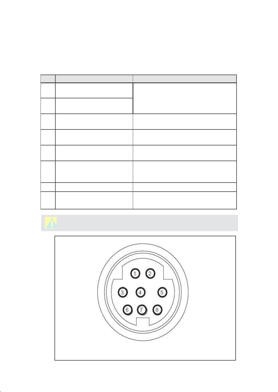
3.
ELECTRICAL CONNECTIONS
DPM is equipp ed with an 8 pin -Min iDIN power,anal og/relay out put,
communication
Figure 1
TABLE I: 8-PIN DESIGNATIONS AND NOTES
PIN FUNCTION
interface connector.
for a Pin Diagram
.
1 Solid State SPST Relay NO
(normally open) contact #1
2 Solid State SPST Relay NO
(normally open) contact #2
3
RS-232 RX / RS-485 (–)
Communication Interface input
4 Analog (0-5Vdc,0-10Vdc,4-20
mA) Output reference (-)
5 RS-232 TX / RS-485(+)
Communication Interface input
6 Analog (0-5Vdc, 0-10Vdc or
4-20 mA) Output (+)
7 Power supply, positive (+)
8
Powersupply, common (-)
RS-232 Signal Ground
Table I
explains the pin designations. See
NOTE
Do not exceed SSR maximum voltage 48
AC peak/DC and maximum load current 400
mA.
Also accessible via Audio jack connector
(
see Figures 2 & 25)
Common (return) for pin 6 (0-5Vdc or
0-10 Vdc or 4-20 mA)
Also accessible via Audio jack connector
see Figures 2 & 25).
(
Output. Do not apply external voltage
current source. Be sure to observe
or any
recommended load
impedance.
Power input 9 – 26 Vdc.
Power input and RS-232 communication
common.
CAUTION:
FIGURE 1: DPM 8-PIN Mini-DIN CONNECTOR CONFIGURATION
4-20 mA analogoutput requires at least 12 Vdcpower.
6
Page 9

CAUTION: Generally, "Mini-DIN" Connector numbering patterns are
standardized. There are, however, some connectors with
nonconforming patterns, so the numbering sequence on your mating
connector may or may not coincide with that shown in our pin
configuration above. It is imperative that you match the appropriate
wires in accordance with the correct sequence regardless of the
particular numbers displayed on the mating connector.
3.1
The AC to DC power supply requirements for DPM transducers are 9 to 26 Vdc, with
maximum load current at least 100 mA (unipolar power supply), and maximum ripple
below 150 mV P-P.
Power can be applied to the DPM meter either through the power jack (see Figure
) or the 8-pin Mini-DIN connector (see Figure 1).
Power Supply Connections
CAUTION:
as this may damage the instrument.
DC Power (+) --------------- pin 7 of the 8-pin Mini-DIN connector
DC Power (-) --------------- pin 8 of the 8-pin Mini-DIN connector
CAUTION:
damage the DPM and/or cause faulty operation.
CAUTION:
any cables or wires to or from the system.
NOTE:
time-lag) r eset fuse. If a shorti ng condition or pol arity reversal occ urs, the
fusewill cut power to the flow transducercircuit: disconnectthe power to the
unit, correct the faulty condition, and reconnect the power. The fuse will
reset once the faulty condition has been corrected.
Never apply power simultaneously from both connectors,
Never apply power voltage above 26Vdc. Doing so may
Make sure power is OFF when connecting or disconnecting
The (+)and (-) power inputs are each protected by a 300mA M(medium
3.2
Output Signals Connections
CAUTION:
exceed the rated values shown in the specifications (see Section 5).
Failure to do so might cause damage to this device. Be sure to check
if the wiring and the polarity of the power supply are correct before
turning the power ON. Wiring error may cause damage or faulty
operation.
When connecting the load to the output terminals, do not
7
Page 10

DPM series Mass Flow Meters are equipped with calibrated 0-5Vdc, 0-10Vdc or
4-20 mA output signals. This linear output signal represents 0-100% of the flow
meter’s full scale range. The user may select the desired analog interface type
using a local OLED/Joystick interface or via digital communication interface.
CAUTION:
isolated, sourcing type). Do not connect an external voltage source
(for example, current loop powered systems) to the output signals.
For 0-5 VDC, 0-10 VDC or 4-20 mA output signal connection:
External load Plus (+) --------------------------- pin 6 of the 8-pin Mini-DIN connector
External load Minus (-)--------------------------- pin 4 of the 8-pin Mini-DIN connector
CAUTION:
check actual analog output interface configuration. Connecting low
impedance (< 5K
damage to or faulty operation of the electronics circuitry.
NOTE:
CAUTION:
always check actual analog output interface configuration.
Connecting high impedance (> 500
may cause non linear or faulty operation of the electronics circuitry.
Toeliminate the possibility of noise interference, it is recommended that you use a separate cable
entry for the DC power, digital communication interface, and analog output interface signal
lines.
The 4-20 mA current loop output is self-powered (non-
When connecting the load to the output terminals, always
ȍ
) loads to the 0-5Vdc or 0-10 Vdc output may cause
4-20 mA analog output requires at least 12 Vdc power input.
When connecting the load to the output terminals,
ȍ
) loads to the 4-20 mA output
3.3
The digital interface operates via RS-232 or RS-485 (user-selected) and provides access to
all applicable internal configuration parameters and data.
Digital Communication Interface Connections
CAUTION: Before proceeding with communication interface
connection, verify the meter’s actual communication interface type. For
devices with OLED display, the interface type will be briefly (for about
2 seconds) displayed on the banner screen when power is applied. If
your meter does not have a display, the communication interface type
can be identified by briefly pressing the multi-function button and
(
see
monitoring status LED response
Section 6.5).
8
Page 11

Communication Settings for RS-232/RS-485 communication interface
The default baud rate is 9600 baud (user-selected; see Section 5, Specifications).
Stop bit:
Data bits:
Parity:
Flow Control:
RS-232 Communication Interface Connection
Crossover connection must be established:
HOST PC RS-232 RX Meter (RS-232 TX)
(pin 2 on the host PC DB9 connector)------pin 3 (Ring) of the 3-pin stereo jack
connector (TX+)
HOST PC RS-232 TX Meter (RS-232 RX)
(pin 3 on the host PC DB9 connector)------ pin 2 (Tip) of the 3-pin stereo jack
connector (RX-)
HOST PC RS-232 SIGNAL GND Meter (Digital GND)
(pin 5 on the host PC DB9 connector)------pin 1 (Sleeve) of the 3-pin stereo jack
connector
Each DPM ordered with RS-232 interface option is supplied with default crossover -
foot long communication cable (AALBORG P/N: CBL-A232) DB9 female to stereo 3.5 mm
Plug.
If custom length cable is required, it can be assembled using the connection
diagram shown in Figure 2.
....................
....................
....................
....................
1
8
None
None
9
Page 12

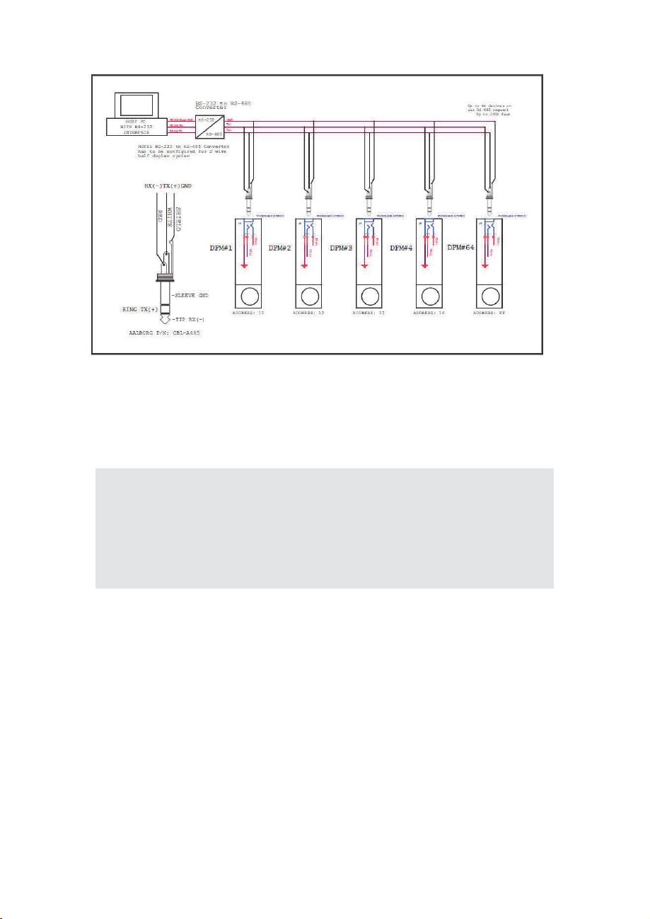
RS-485 Communication Interface Connection
The RS-485 converter/adapter must be configured for: multidrop, 2-wire, half
duplex mode (see Figure 3). The transmitter circuit must be enabled by TD or
RTS (depending on which is available on the converter/adapter). Settings for
the receiver circuit should follow the selection made for the transmitter circuit
in order to eliminate echo.
RS-485 A line T(-) or R(-) ............. pin 2 on 3-pin Audio-connector, middle
section or "tip" DPM (RX-), (WHITE
wire)
RS-485 B line T(+) or R(+) ........... pin 3 on 3-pins Audio-connector, the
"ring" section DPM (TX+), (RED wire)
RS-485 GND (if available) ............ pin 1 on 3-pin Audio-connector, the
“sleeve” section DPM (GND), (Shield
wire)
Each DPM ordered with RS-485 interface option is supplied with a default
3-foot length of communication cable (AALBORG P/N: CBL-A485) Stereo
3.5 mm plug to stripped wires.
If custom length cable is required, it can be assembled using the connection
diagram shown in Figure 3:
10
Page 13
F
IIGGUURRE3:DDPPMRR
When the DPM device is set as the last device on the long RS-485 bus segment,
ȍ
the 120
and (-) terminals close (< 6 feet) to this device.
bus termination resistor must be connected between the RS-485 (+)
SS-
44885CCOO
MMMM
UUNNIICC
ATTIIOONN IINNTTEERRFFAACCECCOO
NNNNEECCTTIIOONN
S
NOTE:
Wermination resistor between the RS-485 (+) and (-) pins. On
instruments with a local display and joystick interface, the 120ȍ
termination resistor can be activated (enabled) using General
Settings / Communication Port / RS-485 Termination menu selection.
By default, the instrument is shipped from the factory with the RS-485
Termination mode set to Disabled.
The DPM instrument offers an integrated switchable 120ȍ
11
Page 14

4.
PP
RRIINNCCIIPPLLEOOFFOOPPEERRATTIIOONN
The DPM series flow meters integrate precision a differential pressure sensor
which accurately measures pressure drop across the special restriction flow
element (RFE). The geometry of the RFE is designed to ensure laminar flow in
each branch within the entire range of operation of the DPM instrument.
According to principles of fluid dynamics, the volumetric flow rates of a gas in the
laminar flow conduits are proportional to differential pressure across the
restriction flow element. In addition, precision absolute pressure and temperature
sensor readings are used to calculate mass flow rate using ideal gas laws.
The DPM flow meter supports multi-gas functionality which allows users on site to
select the desired measured gas using local Display/Joystick interface or digital
communication interface. See Tables X - XVIII which provide lists of supported
gases.
The DPM flow meter can display flow rate in 43 different mass flow or 15 different
volumetric flow engineering units. Flow meter parameters and functions can be
programmed locally via optional OLED/Joystick interface or remotely via the RS232/RS-485 interface or optional Modbus RTU interface. DPM flow meters
support various functions including two programmable flow totalizers; low, high or
range flow; temperature and pressure alarms; automatic zero adjustment
(activated via local or digital communication interface); programmable solid state
relay (SSR); programmable 0-5 Vdc, 0-10 Vdc or 4-20 mA analog outputs; userprogrammable pulse output (via SSR); and self-diagnostic alarms. Optional local
OLED readout with adjustaEOH brightness level provides mass and volumetric
flow rate, total volume reading in currently selected engineering units, and
GLDJQRVWLFHYHQWVDQGLQGLFDWLRQ
5.
FLOW MEDIUM:
clean gases,
CALIBRATIONS:
°C]) unless otherwise requested orstated.
ENVIRONMENTAL (PER IEC 664):
FLOW ACCURACY (INCLUDING LINEARITY):
temperature and pressure.
REPEATABILITY:
FLOW TEMPERATURE COEFFICIENT:
FLOW PRESSURE COEFFICIENT:
FLOW RESPONSE TIME:
SSPPEECCIIFFIICCA
Please note that DPM Mass Flow Meters are designed to work only with
never
TTIIOONN
S
any corrosive gas and
Performed at standard conditions (14.7 psia [101.4 kPa] and 70 °F [21.1
+0.15% of full scale.
default 10 ms (user-adjusted).
never
Installation Level II; Pollution Degree II.
0.05% of full scale/ °C or less.
0.01% of full scale/psi (6.895 kPa) or less.
12
any liquid.
±(0.5% RD + 0.2% FS) at calibration
Page 15

INSTRUMENT WARM-UP TIME:
< 5 seconds.
MAXIMUM MEASURABLE FLOW RANGE:
OPERATION RANGE/TURNDOWN RATIO:
MASS REFERENCE CONDITIONS (STP): 70°f & 14.696 PSIA(other references
available on request).
MAXIMUM INTERNAL GAS PRESSURE (STATIC):
'3036,*
%5((=(/RZ'LIIHUHQWLDO3UHVVXUHPRGHOV'3036,*
0$;,080,167$17$1(286',))(5(17,$/35(6685($&5266,1/(7$1'287/(7
PROOF PRESSURE:
%5((=(/RZ'LIIHUHQWLDO3UHVVXUHPRGHOV'3036,*
TEMPERATURE:
MOUNTING ATTITUDE SENSITIVITY:
RELATIVE GAS HUMIDITY RANGE:
INGRESS PROTECTION:
2873876,*1$/6
'30 36,'
%5((=(/RZ'LIIHUHQWLDO3UHVVXUHPRGHOV'3036,'
'3036,*
-WRÛ&WRÛ)
IP40.
Linear 0-5 (3000 min. load impedance);
/LQHDU PLQORDGLPSHGDQFH
/LQHDUP$ PD[LPXPORRSUHVLVWDQFH
0D[LPXPQRLVHP9SHDNWRSHDNIRURXWSXW
TRANSDUCERINPUTPOWER:
noise. Power consumption: 100 mAmaximum.
133% Full Scale.
0.5% to 100% Full Scale / 200:1.
OPERATING
None.
0 to 100% (Non-Condensing).
9 to26Vdc,150mVmaximumpeaktopeakoutput
Circuit boards have built-in polarity reversal protection, and a 300mA resettablefuse
provides power input protection.
DIGITAL OUTPUT SIGNALS:Standard RS-232 or RS-485 (user-selected).
Optional Modbus over isolated RS-485 transceiver
:(77('0$7(5,$/66WDLQOHVVVWHHO9LWRQ2ULQJVKLJKWHPSHUDWXUH
SRO\DPLGHDOXPLQDFHUDPLFHSR[\VLOLFRQHJODVVJROG
CAUTION:
corrosion resistance of mass flow meters as pertains to different
flow media reacting with any components of the meters. It is solely
the customer’s responsibility to select the model best suited for a
particular gas, based on the fluid contacting (wetted) materials
offered in the different models.
Aalborg® makes no expressed or implied guarantees of
.
13
Page 16
INNLL
E E
T T
1/8"
AANND OOUUTTLL
NPT
E E
TT
CCOO
NNNNEECCTTIIOONNSS
:: DPM04/07
10-32
female
thread, DPM14/17/37
female thread, DPM24/34/47 1/4" NPT female thread , DPM44/57 1/2" NPT
female thread, DPM54/67/77 3/4" NPT female thread for user-supplied fittings.
DISPLAY: Optional 128 x 64 pixels graphic yellow OLED with Esc button and
Joystick interface. Simultaneously displays: Mass Flow, Totalizer Volume,
Pressure and Temperature or Mass Flow, Volumetric Flow, Pressure and
Temperature (user-selectable screens).
5..11
CCEECommpp
lliiaannccee
EMCCompliancewith2004/108/ECas amended. CISPR11
Emission Standard: EN61000-6-3, Group 1, Class A
Immunity Standard: EN61000-6-1, IEC EN 61000-4-2, IEC EN 61000-4-3
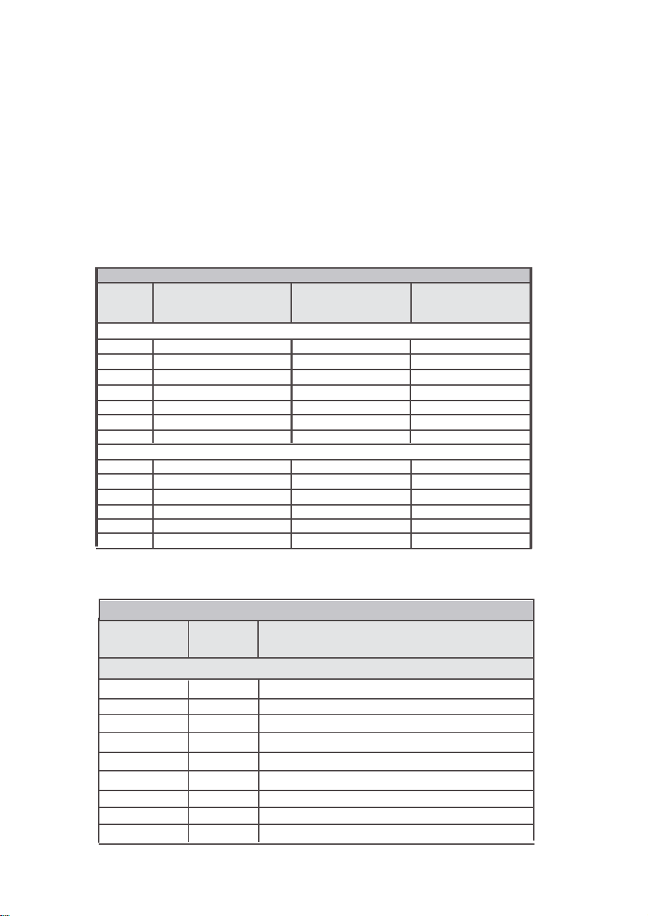
TABLE II: DPM FLOW RANGES
MODEL
NO.
DPM07
DPM17
DPM37
DPM47
DPM57
DPM67
DPM77
DPM04
DPM14
DPM24
DPM34
DPM44
DPM54
FULL SCALE MASS
FLOW RATE
STANDARD PRESSURE DROP [AIR]
0.5 to 50 sml/min
51 sml/min to 20 sl/min
21 sl/min to 50 sl/min
51 sl/min to 100 sl/min
101 sl/min to 250 sl/min
251 sl/min 500 sl/min
501 sL/min to 1000 sL/min
DPM (BREEZETM) LOW PRESSURE DROP [AIR]
0.5 smL/min to 20 smL/min
21 smL/min to 2 sL/min
2.1 sL/min to 10 sL/min
10.1 sL/min to 20 sL/min
20.1 sL/min to 40 sL/min
40.1 sL/min to 100 sL/min
PRESSURE DROP
AT FULL SCALE
FLOW (PSID)
1.0
1.0
2.0
2.5
5.5
5.5
7.0
0.06
0.07
0.085
0.3
0.15
0.25
PROCESS
CONNECTION
10-32 Female Thread
1/8" NPT Female
1/8" NPT Female
1/4" NPT Female
1/2" NPT Female
3/4" NPT Female
3/4" NPT Female
10-32 Female Thread
1/8" NPT Female
1/4" NPT Female
1/4" NPT Female
1/2" NPT Female
3/4" NPT Female
5..11
DPM Accessories
MODEL
NO.
DPM07 / 04
DPM07 / 04
DPM17 / 14
DPM17 / 14
D PM37 / 34
DPM24 / 34 / 47
DPM44 / 57
DPM54 / 67
DPM54 / 77
FITTING
CODE
F1C5
F2C5
F2C2
F2C4
F4C4
F4C6
F8C6
1210-1-12-316
1210-1-12-316
TABLE III: DPM ACCESSORY'S
DESCRIPTION
FITTINGS
10-32 Thread, 1/8" Tubing, Compression, 316 ss.
10-32 Thread, 1/8" Tubing, Compression, 316 ss.Nickel Plated Brass
1/8" NPT Thread, 1/8" tubing, Compression, 316 ss.
1/8" NPT Thread, 1/4" tubing, Compression, 316 ss.
1/4" NPT Thread, 1/4" tubing, Compression, 316 ss.
1/4" NPT Thread, 3/8" tubing, Compression, 316 ss.
1/2" NPT Thread, 3/8" tubing, Compression, 316 ss.
3/4" NPT Thread 3/4" tubing, Compression, 300 series ss.
3/4" NPT Thread 3/4" tubing, Compression, 300 series ss.
14
Page 17

MODEL NO.
PS-GFM-110NA-2
PS-GFM-110NA-4
PS-GFM-230EU-2
PS-GFM-230EU-4
PS-GFM-240UK-2
POWER SUPPLIES
DESCRIPTI ON
Power Supply, 110 V / 12 Vdc / North America.
Power Supply, 110 V / 24 Vdc / North America.
Power Supply, 220 V / 12 Vdc / Europe.
Power Supply, 220 V / 24Vdc / Europe.
Power Supply 240 V / 12 Vdc / United Kingdom.
5..22
DDPPMAAcccce
CBL-A232
CBL-A485
CBL-8MINIDIN-3
CBL-8MINIDIN-12
USB-RS-232
USB-RS-485
ECS803-1
TDG1026-8C
MOD27T
JMOD4S-1
TRD815BL-2
TRD815BL-10
TRD815BL-25
TRD815BL-10
TRD815BL-25
ssssoorriiees
CABLES
Communication Cable for DPM with RS-232 Interface FT
3.5mm
stereo audio connector with 3-wire to 9-pin female
D-connector
Communication Cable for DPM with RS-485 Interface 3 FT
3.5m m
Shielded cable 8-pin Min-DIN with stripped ends 3 feet long
Shielded cable 8-pin Min-DIN with stripped ends 12 feet long
COMMUNICATION PORT ACCESSORIES
USB to RS-232 converter
USB to RS-485 converter
MODBUS INTERFACE ACCESSORIES
RJ45 shielded Y-adapter (Passive TAP).
RJ45 Modular Coupler.
RJ45 Line Terminator (100 ȍ0.25 W).
RJ45 Splitter fully shielded (5xRJ45, 1 input 4 outputs).
Category 5E Patch Twisted Pair Cable, RJ45 / RJ45, Blue 2.0 feet.
Category 5E Patch Twisted Pair Cable, RJ45 / RJ45, Blue 10.0 feet.
Category 5E Patch Twisted Pair Cable, RJ45 / RJ45, Blue 25.0 feet.
Category 5E Patch Twisted Pair Cable, RJ45 / RJ45, Blue 10.0 feet.
Category 5E Patch Twisted Pair Cable, RJ45 / RJ45, Blue 25.0 feet
(included with each DPM).
stereo audio connector with 3-wire to stripped ends.
15
Page 18

MOODDEELL
DPM 07/17
DPM 47
DPM 57
DPM 67
DPM 77
DPM04
DPM14
DPM24
DPM34
DPM44
DPM54
TABLE IV: PRESSURE DROPS
M
FLLOOWRRAATTEE
[ssttdll iitteerrss//mmiinn
STANDARD PRESSURE DROP [ AIR]
up to 10 703
100 1757 2.5 17.236
200
500
1000
DPM (BR EEZE) LOW PRESSURE DROP [AIR]
0.02
10
2 0
4 0
100
]
[
mmmm
20
30
40 1406 2.0 13.789
50 1406
60 1757
2
105.5
AAXXIIMMUUMM
H2O
] [
703 1.0 6.894
1406 2.0 13.789
TBD
TBD TBD TBD
TBD TBD TBD
42.2
49.2
59.8
210.9
175.8
PPRREESSSSUURREEDDRROOPP
ppssiidd
] [kkPPaa]]
1.0
2.0 13.789
2.5
TBD TBD
0.06
0.07
0.085
0.3
0.15
0.25
6.894
17.236
0.413
0.483
0.586
2.068
1.034
1.724
TABLE V: APPROXIMATE WEIGHTS
MOODDEELL WEEIIGGHH
DPM04/07/14/17 flow meter
DPM34/37/44/47 flow meter
DPM54/57 flow meter
DPM67 flow meter
DPM77 flow meter
6.
6..11
Now that the Mass Flow Meter has been correctly installed and thoroughly testedas
describedin
turnedon,theBannerScreenisshownfor 2 seconds (see Figure 4), then device
firmware and
communication interface type and hexadecimal address value on the second line,
Communication Port baud rate on the third line, andModbushardwarestatusand decimal
addressvalueonthefourthline (see
Subsequently, the actual process information (PI) is displayed.
OOPPEERRA
PPrreeppaarraattiioonaanndPPoo
TTIINNGGIINNSSTTRRUUCC
Section 2
, makesuretheflowsourceisOFF.Initially, afterthepower
EEPROM database revisions will be displayed on the first line,
0.85 lbs. (0.4 kg) 2.55 lbs. (1.2 kg)
1.15 lbs (0.52 kg) 3.0 lbs (1.36 kg)
3.5lbs (1.6kg) 5.1lbs (2.32kg)
4.5lbs (2.04kg)
5.2lbs (2.35kg)
wweerUU
Figure 5
T
TTIIOONN
SS
pp
). These areshownforanother
SHHIIPPPPIINNGWWEEIIGGHH
6.7lbs (3.04kg)
8.75lbs (3.97kg)
TT
is first
2 seconds.
16
Page 19

Fiigguurre
44::
DPPMMfirrsst BBaa
FFww:AA000011TTbbll::AA000011
CCOOMM::RRSS
BBaauuddRRaattee
MM
ooddBBuuss:
22332AAdddd::1111
:99660000
YAA
dddd::1111
nnnneerr SSccrreeee
nn
Fiigguurre55::
The main DPM flow meter screen shows current instrument Pressure, Temperature,
Mass Flow, and Totalizer Volume readings in previously selected units of measure.
DPPMMFF
ii rr
mmwwaarr
eeaa
nndCCoo
mmmm
uunniiccaattiioon
Absolute Pressing
Reading
PSIA
0.00
Current Mass Flow
Rate Reading
22.67
T1: 14726.0 Sml
Totalizer #1 Reading
Figure 6: DPM Initial Process Information
NOTE:
the model and device configuration.
NOTE:
the status LED will emit a constant GREEN light (normal operation,
ready to measure).
Actual content of the OLED screen may vary depending on
5 seconds after the initial powering of the DPM flow meter,
IInntteerffaaccee
27.7
Sml
min
IInnff
oormationSSccrreeee
Temperature
Reading
Current Unit of
C
Measure for
Mass Flo w
Totalizer#1
Units of
Measure
nn
6..22
If a flow of more than 133% the nominal maximum flow rate of the Mass Flow
Meter is taking place (displayed mass flow reading is flashing), a condition
known as "swamping" may occur. Readings of a "swamped" meter cannot be
assumed to be either accurate or linear. Flow must be restored to below 133%
of maximum meter range. Once flow rates are lowered to within calibrated
range, the swamping condition will end.
SSwwaa
mmppiinn
ggCCoonnddiittiioo
n
17
Page 20

6..33
MMeetteerPPrrooccee
sssIInn
ffoorrmm
aattiioon((PPII))ss
ccrr
eeenns
Based on meter configuration, different parameters may be displayed in the
Process Information (PI) screen by moving the control joystick (see Figure
7) Up or Down (DN). Process Information screens can be configured to be
static or dynamic (see Section 6.4.13.2 “Display and Process Information
(PI) Screens”). Using PI Screen Mask settings, the user can enable
(unmask) or disable (mask) up to 6 different process information
combinations.
UP
LEFT
Press here for
Enter command
RIGHT
DOWN
FIGURE 7: JOYSTICK
In the Static Mode, moving the joystick Up pages through the PI screens in
the forward direction, while moving the joystick DN pages through the PI
screens in the reverse direction. When the last PI screen is reached, the
firmware “wraps around” and scrolls to the initial PI screen once again.
In the Dynamic Display Mode, the firmware initiates automatic screen
sequencing with user-adjusted screen Cycle Time (see Section 6.4.13.2
“Display and Process Information (PI) Screens”). When the last PI screen is
reached, the firmware “wraps around” and scrolls to the initial PI screen
once again.
18
Page 21

PSIA
222..7777
0..000
T
11::144772266..00Sm
255..7
PI Screen #1 (Pressure, Temperature,
C
Mass Flow Rate, Totalizer #1)
Smmll
miinn
l
Com. Interface type
and device address
Analog Interface Type
Flow, Pressure,
Temperature
Alarms Status
Totalizers Status
Alarm Events Status
Register
PSIA
222..7777
255..5
Smmll
0..000
T
22::0..00Sm
222..7777
PSIA
miinn
244..5
Smmll
0..000
V
::0..00mll//mmiin
miinn
AAIIR
FFSS:00..22000000LL//mmiin
RRSS
22332
00
--55VV
ddccMMooddbbuuss::
PPOOWWEERR
::1199..66HHrr
AAllmm::DDDDD RReell::D
TT
11::DD TT22::EE PPOO::DD
A
EE
::00000000DDEE
::0000000
PI Screen #2 (Pressure, Temperature,
C
Mass Flow Rate, Totalizer #2)
l
PI Screen #3 (Pressure, Temperature,
C
Mass Flow Rate, Volumetric Flow Rate)
PI Screen #4 (Selected Gas, Instrument
Full Scale Range, Interface Information)
Currently Selected Gas Name
Instrument Full Scale Range
YY
Modbus interface H/W status (Y, N)
PI Screen #5 (Events Notification screen)
Time elapsed from the power up event
Relay assignment
Pulse Output Status
Diagnostic Events Status Register
PI Screen #6 (Instrument Diagnostic)
DP Sensor Raw Counts
AP Sensor Raw Counts
DP Sensor reading mBar
Temperature Sensor
Raw Counts
FIGURE 8: DPM PROCESS INFORMATION SCREENS
DD
::11664433553399001
AA::--
44110066337
DDPP
:00..00005
T:226688335
00..00000011
2244..8833
88998
19
DP Sensor Temperature Raw Counts
AP Sensor Temperatur e Raw Counts
DP sensor reading in PSID
CC
Temperature Sensor Reading (deg.C)
Page 22

6..44
LLooccaalUUsseerrIInntteerrffaacc
The diagram in Figure 13 gives a general overview of the standard top-level
display menu structure (when running firmware version A001). The Esc
push-button is used to toggle between the Process Mode (PI screens) and
the Setup menus, and to return to upper menu level.
In order to move through the menu items, the user must move the joystick
UP and DN. When the last item in the menu is reached, the menu “wraps
around” and scrolls back to the beginning of the menu items list. Similarly,
when the first menu item is highlighted and the joystick is moved UP, the
menu “wraps around” and scrolls down to the end of the menu item’s list. In
order to select the desired menu item, the user must press the joystick
down (this action is equivalent to the Enter button). To go back to upper
menu level, the user must press the Esc button.
All process configuration parameter settings are password-protected. In
order to access or change them, Program Protection (PP) should be
disabled. Each time the device is powered up, the Program Protection is
enabled automatically. By default, the device is shipped from the factory
with the Program Protection (PP) password set to Zero (PP Disabled). If the
PP password is set to Zero (Disabled), entering a PP password is not
required. A subsequent screen will appear and the Program Protection
menu item will be selected:
Fiigguurre
eMMee
nnuuSS
ttrruuccttuurr
PRR
OOGG
RRAAMMPPRROOTTEECCTTIIOONN
E
NNAABBLLEE
DIISSAABBLLEE
uusshUUpp,,DDn
P
settttiinngg,,EEnn
seettttiinngg,EEssc
9: Program Protection Screen
tt
oocchhaanngg
t ttooSSaavv
ttooEExxii
:
DD
D
ee
ee
tt
e
Moving the joystick DN to select the Disabled option and then pushing the
joystick (ENT) to save settings will disable program protection.
If the PP password is set to any value more than Zero, the firmware will
prompt with “Enter Program Protection Password” (see Figure 10).
Enntteerr PPrr
ooggrraamPPrrootteeccttiioonn
Paasssswwoorrdd::
P
uusshUUpp,,DDn
seettttiinngg,EEnn
seettttiinngg,EEssc
Figure 10: Program Protection Password Screen
The user must enter up to 3 digits for the program protection code, in order
to be able to access password protected menus.
tt
oocchhaanngg
t ttooSSaavv
ttooEExxii
ee
ee
tt
20
Page 23

NOTE:
Program Protection (PP) password set to Zero (PP Disabled).
Once the correct password is entered, the Program Protection is turned off
until the unit is powered up again.
By default, the device is shipped from the factory with the
6..44..11PPaarraammeetteerEEnnttrr
There are two methods of data entry:
x Direct numerical entry.
x Tabular Input from a menu.
If the menu with direct numerical entry is selected, move the joystick UP or DN
to increase or decrease digit value between 0-9. Move the joystick RIGHT or
LEFT to move the cursor to another digit position. When the desired value is
entered, use joystick equivalent of an ENT button to accept (to be saved in the
EEPROM) the new value
NOTE:
acceptability. If data is not acceptable, it is rejected and a message
is generated to indicate that the new data has not been accepted.
If the menu with tabular entry is selected, the available menu options can be
set using the joystick UP and DN positions and are accepted by pressing the
joystick equivalent of an ENT button.
6..44..22
In order to get access to “Change Program Protection (PP) Password”
menu, Program Protection must be disabled. If PP password is set to Zero
(Disabled), entering PP Password is not required and PP can be disabled
from “Program Protection” menu (see Figure 9). If PP Password is set to
any value more than Zero, the firmware will prompt with “Enter Program
Protection Password” (see Figure 10). The user must enter a program
protection code (up to 3 digits). If the PP password is lost or forgotten,
contact the factory or your distributor.
During data entry, the input values are checked for
SSuu
bbmmeennu““CChhaannggePPPPPPaasssswwoorrdd
y
.
”
Once the “Change PP Password” menu is selected, the following screen will appear:
OOlld
PPPPPPaasssswwoorrdd:
NNeew
PPPPPPaasssswwoorrdd:
EEnntteer OOlldPPPPPPaasssswwoorrdd
Figure 11: Change PP Password Screen
21
Page 24

In order to protect device configuration parameters when changing the PP
password, the old PP password must first be entered.
Once old and ne w passwords are ent ered, the firmwa re will prompt wit h a
confirmation
message (see
Figure 12: PP Password Change Confirmation Screen
Figure 12
) that thenew password hasbeen saved:
Neeww
PPPPPPaasssswwoorrdd
h
aa
ssbb
eeee
nnssaavveed
PP PPaasssswwoorrddiissCChhaannggeed
..44..33SSuu
6
This submenu contains information about the device’s main configuration parameters.
These items are informational only, not password-protected, and cannot be changed
(read only).
6..44..44
Use the “Units of Measure" Menu to navigate to Measuring Units settings for
Mass Flow, Volumetric Flow, Pressure, and Temperature readings. This option
allows configuration of the flow meter with the desired units of measurement.
These are global settings and determine what appears on all Process
Information screens and in all data log records. Units should be selected to
meet your particular metering needs. A total of 44 different mass-based
engineering units (Standard, Normal and True Mass) are supported (see Table
VI). A total of 15 different volumetric flow rate units are supported (see Table
VII).
Supported Pressure units of measure are listed in Table VIII, and Supported
Temperature units of measure are listed in Table IX.
bbmmeennu““DDeevviicceIInnffoorrmm
SSuu
bbmmeennu““UUnniitt
ssooff
aattiioonn””
MMeeaassuurree””
22
Page 25

TABLE VI: LIST OF SUPPORTED MASS FLOW UNITS OF MEASURE
USER DEFINED
44 USER U
U
d
Number
1
2
3
4
5
6
7
8
9
10 Sm3/min Sm3
11 Sm3/hr Sm3
12 Sm3/day Sm3
13 Sf3/sec Sf3
14 Sf3/min Sf3
15 Sf3/hr Sf3
16 Sf3/day Sf3
17 gr/sec gr
18 gr/min gr
19 gr/hr gr
20 gr/day gr
21 kg/min kg
22 kg/hr kg
23 kg/day kg
24 lb/min lb
25 lb/hr lb
26 lb/day lb
27
28 oz/min
29 NuL/min NuL
30 NmL/sec NmL
31 NmL/min NmL
32 NmL/hr NmL
33
34 NL/min
35 NL/hr
36 NL/day
37 Nm3/min Nm3
38 Nm3/hr Nm3
39 Nm3/day Nm3
40 Nf3/sec Nf3
41 Nf3/min Nf3
42 Nf3/hr Nf3
43 Nf3/day Nf3
Mass Flow Rate
Units
%FS
SuL/min
SmL/sec SmL
SmL/min SmL
SmL/hr SmL
SL/sec SL
SL/min
SL/hr
SL/day SL Liter per day
oz/sec oz
NL/sec NL
Totalizer Volume Units
STANDARD
TRUE MASS
NORMAL
Description
%s
SuL
SL Liter per minute
SL Liter per hour
oz
NL Liter per minute
NL Liter per hour
NL Liter per day
Percent of Full Scale
Microliters per minute
Milliliter per second
Milliliters per minute
Milliliter per hour
Liter per second
Cubic meter per minute
Cubic meter per hour
Cubic meter per day
Cubic feet per second
Cubic feet per minute
Cubic feet per hour
Cubic feet per day
Grams per second
Grams per minute
Grams per hour
Grams per day
Kilograms per minute
Kilograms per hour
Kilograms per day
Pounds per minute
Pounds per hour
Pounds per day
Ounce per second
Ounce per minute
Microliters per minute
Milliliter per second
Milliliters per minute
Milliliter per hour
Liter per second
Cubic meter per minute
Cubic meter per hour
Cubic meter per day
Cubic feet per second
Cubic feet per minute
Cubic feet per hour
Cubic feet per day
23
serDefine
Page 26

TABLE VII: LIST OF SUPPORTED VOLUMETRIC FLOW UNITS OF MEASURE
Number
1
2
3
4
5
6
7
8
9
10 m3/min m3
11 m3/hr m3
12 m3/day m3
13 f3/sec f3
14 f3/min f3
15 f3/hr f3
16 f3/day f3
Number
1
2
3
4
5
6
7
8
9
10 inHgA inHg
11 mmHgA mmHg
12
13
14 TorrA torr Torr
15
Flow Rate Units
%FS
uL/min uL
mL/sec mL
mL/min mL
mL/hr mL
L/sec
L/min
L/hr
L/day
TABLE VIII: LIST OF SUPPORTED ABSOLUTE PRESSURE UNITS OF MEASURE
Pressure Units Name Short Name
PSIA
barA barA
mbarA mbar Millibar
hPaA hPaA
kPaA kPaA
MPaA MPaA
atm atm Atmosphere
g/cm2A gcm2
kg/cmA kgc2
cmH2OA
inH2OA
%FS %FS
Totalizer Volume Units
%s
L
L
L
L
psiA
Gram-force per square centimeter
Kilogram-force per square centimeter
cmH2
inH2
Pound per square inch
,QFKRIPHUFXU\>Û&@
Millimeter RIPHUFXU\>Û&@
&HQWLPHWHURIZDWHU>Û&@
,QFKRIZDWHU>Û&@
Percent of Full Scale
Description
Percent of Full Scale
Microliters per minute
Milliliter per second
Milliliters per minute
Milliliter per hour
Liter per second
Liter per minute
Liter per hour
Liter per day
Cubic meter per minute
Cubic meter per hour
Cubic meter per day
Cubic feet per second
Cubic feet per minute
Cubic feet per hour
Cubic feet per day
Description
bar
Hecto Pascal
Kilo Pascal
Mega Pascal
Number
1
2
3
4
TABLE IX: LIST OF SUPPORTED TEMPERATURE UNITS OF MEASURE
Temperature Units Label
Û) degree Fahrenheit
Û& degree Celsius
K
Û5
Description
Kelvin
degree Rankine
24
Page 27

NOTE:
may be based on the units selected. Once Flow Unit of Measure is
changed, the Totalizer’s Unit of Measure will be automatically updated.
Program the Measuring Units first because subsequent menus
6..44..55““SSuu
In addition to conventional flow units, user-defined flow engineering units
may be selected. Use the “Engineering Units and K-Factor” menu to
navigate to the “User-Defined Units” menu option. This option enables userdefined configuration of any engineering unit required for process
measurement.
The following three parameters are available for this function:
x UD Unit volume K-Factor (defined in Liters)UD Unit time base
x UD Unit use density (units with or without density support)
Before using the User-Defined Unit, be sure the proper conversion factor of
the new unit, with respect to one liter, is set. The default entry is 1.00 Liter.
Also, proper time-based values for User-Defined Units must be set.
Figure 13 explains by diagram the various upper level display menus.
bbmmeennuuUUsseerr--DDee
(defined in Seconds)
fifinneedUUnniittss”
25
Page 28
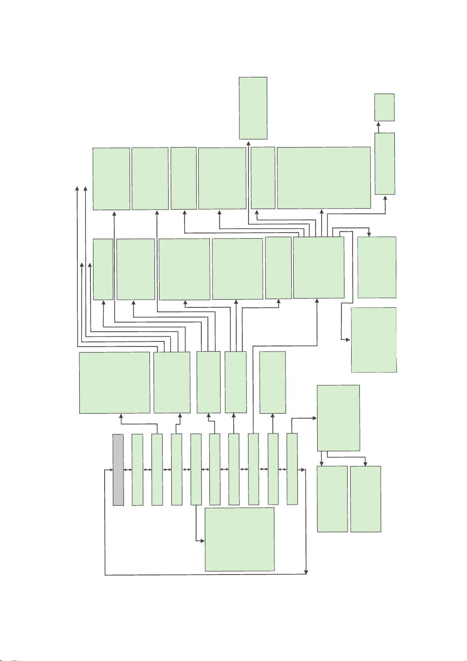
Program Protaction (PP)
Change PP Password
Device Information
Units of Measure
Alarm Settings
Totalizers Settings
General
Settings
Select Gas
***** Main Menu *****
Alarm Event Menu
Diagnostic Events
Sensors ADC Reading
Temperature Sensors
AnalogOut & POQueue
Miscellaneous Param
Sensor Zero Calibr.
Tot
al
izer #1
Tot
al
izer #2
Pul
se Output
Gas Flow Alarm
Gas Pressure Alarm
Gas Temperature Alarm
Mass Flow
Volumetric Flow
Pressure
Temperature
User Defined Unit
Device ID & FS Flow
Analog/Com Interface
Firmware/EE Version
Flow Alarm Settings
Pressure Alarm Set.
Temp Alarm Settings
Totalizer#1 Settings
Totalizer#2 Settings
Pulse Outputs & LEDs
General Settings
Standard Temperature
Standard Pressure
Normal Temperature
Normal Pressure
Display Oper. Mode
Screen Cy
cle Ti
me
PI Screens Config.
OLED
Bright
nes
s
Screen Saver
Mode
OLED SS Time Out
OLED SS Brightness
Flow Rate Prec
ision
Baud Rate Settings
Dev
. ModBus Address
ModBus Com. Parity
ModBus Com. StopBit
Disabled
Low F. Alarm
High F. Alarm
F. Range H - L
Low P. Alarm
High P.
Alarm
P. Range H - L
Low T. Alarm
High T. Alarm
T. Range H - L
Tot
alizer #1 Event
Totali
zer #2 Event
Puls
e Output
Alarm Events
Diagnostic Events
Manual On
Totalizer #1 Mode
Tot#1 Flow Start
Tot#1 Action Vol.
Tot#1 PowerOn Delay
Tot#1 Auto Reset
Tot#1 AutoRes Delay
Reset Totalizer #1
Tot#1 DP Precision
Totalizer #2 Mode
Tot#2 Flow Start
Tot#2 Action Vol.
Tot#2 PowerOn Delay
Tot#2 Auto Reset
Tot#2 AutoRels Delay
Reset Totalizer #2
Tot#2 DP Precision
PulseOutput Mode
Pulse Flow Start
[Unit]/Pulse
Pulse Active Time
STP/NTP Units Cond
Display & PI Screens
Communication P
ort
ModBus Interface
Relay Assignment
Analog Output
Status LED Settings
Signal Conditioner
UD Unit K-Factor
UD Unit Time Base
UD Unit Use Density
Pressure Alarm Mode
Low Pressure Alarm
High Pressure Alarm
Pressure Alarm Delay
Pressure Alarm Latch
PA Power Up Delay
F
low Damping
Flow NLEF Mode
Pressure Damping
Pressure NLEF Mode
LCD Flow Average
Gas Temp. Damping
LCD Flow Dead Band
Recent Gases
Standard Gases
Bioreactor Gases
Breathing Gases
Chromatography Gases
Fuel Gases
Laser Gases
O2
Concen
trat
or
S
tack Gases
Welding Gases
Use Defined Mixture
Alarm & Diagnostic
A
larm Events Status
A
larm Events Mask Reg.
A
larm Events
Latch Reg.
Reset Alarm Events Reg.
Diag.
Events Status
Diag.
Events Mask
Reg.
Diag.
Events Latch Reg.
Reset Diag. Events Reg.
Start Auto Zero Now
Start AP Auto Tare
Vi
ewZeroParameters
Default Events
F. Alarm & Tot Events
Alarm Ev
ent
s
Diagnostic Events
Main Com. Interface
Modbus Interface
Analog Output Mode
Analog Output Cal.
Analog Output Test
0-5 Vdc
0-10 Vdc
4-20 mA
Temp. Alarm Mode
Low Temp. Alarm
High Temp. Alarm
Temp. Alarm Delay
TA Power Up Delay
Temp. Alarm Latch
Flow Alarm Mode
Low Flow Alarm
High Flow Alarm
Flow Alarm Delay
Flow Alarm Latch
FA Power Up Delay
UART Tranceiv Mode
Baud Rate Settings
RS-485 Bus Address
RS-485 Termination
See Table V,,I
See Table V,
See Table I;
See Table V,,
Figure 13 DPM Upper Levels Menu Structure
Page 29

6..44..66
The currently active gas can be selected by the user via OLED/joystick or digital communication
interface. The gas data are allocated in different gas groups (see
“Recent Gases” group keeps up to 16 recently selected gases. The detailed list of the gases for
each group is provided in Tables X through XVIII, beginning on the following page.
For example, to select Nitrogen, the user should navigate to “Select Gas”
then highlight “Nitrogen” and press the joystick equivalent of an
SSuu
bbmmeennu""SSeelleecctGGaass""
Recent Gases
Standard Gases
Bioreactor Gases
Breathing Gases
Chromatograpy Gases
Fuel Gases
Laser Gases
O2 Concentrator
Stack Gases
Welding Gases
User Defined Mixture
Figure 14: Selecting Gas Group
Figure 14
Ent
button.
below). The
Ö
“Standard Gases”,
27
Page 30

TABLE X: Standard Pure Non-Corrosive Gases
AA
ll lDDaattaa
ffoor SStaannddaarrddCC
Gaa
ss
S
Nuummbbee
0
1
2
3
4
5
6
7
8
9
10
11
12
13
14
15
16
17 Kr Krypton 24.839148
18
19
20
21
22
23
24
25
26
27
28 A1025
29 Star29
30
hhoorrtt
r
Naamm
e
Air Air 18.259686
Ar Argon 22.377244
CO2
N2
O2 Oxygen
He
CO Carbon Monoxide
C2H4 Ethylene
C2H6 Ethane
n-C4H10
i-C4H10
C3H8 Propane
D2
H2
N2O
CH4 Methane
Ne Neon
SF6 Sulfur Hexafluoride
Xe
C2H2 Acetylene
C25 25% CO2 / 75% Ar
C10 10% CO2 / 90% Ar
C8 8% CO2 / 92% Ar
C2 2% CO2 / 98% Ar
C75 75% CO2 / 25% Ar
He75 75% He / 25% Ar
He25 25% He / 75% Ar
P5 95% Ar / 5% CH4
LoonngNNaammee
Carbon Dioxide
Nitrogen 17.624584
Helium 19.668342
n-Butane 7.3072193
i-Butane 7.4018705
Deuterium 12.473107
Hydrogen 8.8198202
Nitrous Oxide
Xenon
90% He / 7.5%
Ar / 2.5% CO2
Stargon CS 90%
Ar/8%CO2/2%O2
oonnddiittiioonnss
A
bbssoolluutte
Viissccoossiitt
(μμPPaa--ss))
14.743078
20.3345
17.475804
10.187017 1.168818 0.99401503
9.2398038 1.255226 0.99208387
8.0415054 1.857567 0.98310908
14.654788
10.949931
30.847242
15.042726 6.121213 0.98816832
22.710043
10.334757
20.455223
21.609367 1.672811 0.99905731
21.762981
22.223694
16.611552
23.052769
23.043143
21.314678
21.730903
22.146573
((
770
°°FFaa
nnd 1144..669966
yy
0.16568373
0.16672796
0.083436355
0.66562262
0.83530908
0.53762966
0.31866435
PPSSIIAA
Deennssiittyyg/l
1.2000185
1.6555318
1.8322844
1.1604245
1.3261455
1.1604842
2.4852646
2.4755419
1.8332083
3.4779701
5.4674713
3.4606011
1.6988495
1.6693503
1.6589828
1.7870162
1.2822075
1.6627585
1.6060633
)
Coommpprreessssiibb
0.99963453
0.99932392
0.99473012
0.99976728
0.99930979
1.0004913
0.99959984
0.96854578
0.97234976
1.0005847
1.0005991
0.99430109
0.99816159
1.0004838
0.9978346
0.99450233
0.99244221
0.99859725
0.9991131
0.99927304
0.99639528
1.0005554
1.0000347
1.0005383
0.99911456
0.99928305
ii ll iittyy
28
Page 31

Gaa
ss
Nuummbbee
r
36 Bio-5M
37
38
39
40
41
42
43
44
45
46
47
48
49
50
51
52
53
54
S
hhoorrtt
Naamm
e
Bio-10M
Bio-15M
Bio-20M
Bio-25M
Bio-30M
Bio-35M
Bio-40M
Bio-45M
Bio-50M
Bio-55M
Bio-60M
Bio-65M
Bio-70M
Bio-75M
Bio-80M
Bio-85M
Bio-90M
Bio-95M
AA
ll lDDaattaa
ffoor SSttaannddaarrddCC
LoonngNNaammee
5%CH4 / 95%CO2
10%CH4 / 90%CO2
15%CH4 / 85%CO2
20%CH4 / 80%CO2
25%CH4 / 75%CO2
30%CH4 / 70%CO2
35%CH4 / 65%CO2
40%CH4 / 60%CO2
45%CH4 / 55%CO2
50%CH4 / 50%CO2
55%CH4 / 45%CO2
60%CH4 / 40%CO2
65%CH4 / 35%CO2
70%CH4 / 30%CO2
75%CH4 / 25%CO2
80%CH4 / 20%CO2
85%CH4 / 15%CO2
90%CH4 / 10%CO2
95%CH4 / 5%CO2
TABLE XI: Bioreactor Gases
oonnddiittiioonnss
((
770
°°FFaa
nnd 1144..669966
A
bbssoolluutte
Viissccoossiitt
yy
(μμPPaa--ss))
14.653659 1.7701352
14.559299 1.7147013
14.459421 1.6564349
14.353426 1.5978991
14.24079
14.120874 1.4809418
13.992953 1.4225176
13.856199 1.3641278
13.709659 1.3057712
13.55223
13.382616 1.1891512
13.1993
13.000513 1.0726464
12.784241 1.0144337
12.548154 0.95624539
12.289467 0.89808023
12.004793 0.83993679
11.690063 0.78181364
11.340435 0.72370939
PPSSIIAA
Deennssiittyyg/l
1.5394019
1.2474461
1.1308852
)
Coommpprreessssiibb
0.99498978
0.99523243
0.99544756
0.99567147
0.99588751
0.9960956
0.99629569
0.99648773
0.99667173
0.99684765
0.99701551
0.99717531
0.99732702
0.99747066
0.9976062
0.99773363
0.99785292
0.99796403
0.99806694
ii ll iittyy
29
Page 32

Gaa
ss
Nuummbbee
r
56
57
58
59
60
61
62
63
64
65
66
67
68
69
70
Gaa
ss
Nuummbbee
r
71 P-5
72 P-10
TABLE XII: Breathing Gases
AA
ll lDDaattaa
ffoor SStaannddaarrddCC
S
hhoorrtt
Naamm
e
EAN-32
EAN-36
EAN-40
HeOx-20 20%O2 / 80%He
HeOx-21 21%O2 / 79%He
HeOx-30 30%O2 / 70%He
HeOx-40 40%O2 / 60%He
HeOx-50 50%O2 / 50%He
HeOx-60 60%O2 / 40%He
HeOx-80 80%O2 / 20%He
HeOx-99 99%O2 / 1%He
EA-40
EA-60
EA-80
Metabol
S
hhoorrtt
Naamm
e
32%O2 / 68%N2
36%O2 / 64%N2
40%O2 / 60%N2
Enri Air-40%O2
Enri Air-60%O2
Enri Air-80%O2
Metabolic Exhalant
(16%O2 / 78.04%N2 /
5%CO2 / 0.96%Ar)
TABLE XIII: Chromatography Gases
AA
ll lDDaattaa
ffoor SStaannddaarrddCC
Loonng Nammee
5%CH4 / 95%Ar 22.146573 1.6060633
10%CH4 / 90%Ar 21.899835 1.5565932
Loonng
Naamm
oonnddiittiioonnss
e
((
770
°°FFaa
nnd 1144..669966
A
bbssoolluutte
Viissccoossiitt
yy
(μμPPaa--ss))
18.553594 1.2134468
18.665372 1.2200749
18.77622
21.160783
21.164401
21.120337
20.99441
20.851246 0.7451824
20.714981
20.499515 1.0934087
20.338992 1.3144914
19.15564
19.56039
19.953017 1.3009447
18.04915
oonnddiittiioonnss
((
770
A
bbssoolluutte
Viissccoossiitt
(μμPPaa--ss))
°°FFaa
y
PSSIIAA)
PPSSIIAA
Deennssiittyyg / l
1.2267031
0.39742666
0.40901481
0.51331687
0.62923199
0.86118182
1.2505528
1.2757473
1.2250145
nnd 1144..669966
Deennssiitt
)
yy
g / l
Compressibility
0.99961365
0.99959516
0.9995768
1.000575
1.0005744
1.0005531
1.0005002
1.0004169
1.0002995
0.99993193
0.99934879
0.99951725
0.9994476
0.99937862
0.99952679
Compressibility
0.99928305
0.99924058
30
Page 33

Gaa
Nuummbbee
74
75
76
77
78
79
80
81
82
83
84
T
TABLE XIV: Fuel Gases
AA
ll lDDaattaa
ffoor SStaannddaarrddCC
S
hhoorrtt
ss
rr
Naamm
e
SynG-1
SynG-2
SynG-3
SynG-4
NatG-1
NatG-2
NatG-3
Coal
Gas
Endo
HHO
HD-5
LoonngNNaammee
40%H2 / 29%CO /
20%CO2 / 11%CH4
64%H2 / 28%CO /
1%CO2 / 7%CH4
70%H2 / 4%CO /
25%CO2 / 1%CH4
83%H2 / 14%CO /
3%CH4
93%CH4 / 3%C2H6 /
1%C3H8 / 2%N2 /
1%CO2
95%CH4 / 3%C2H6 /
1%N2 / 1%CO2
95.2CH4 / 2.5%C2H6 /
0.2%C3H8 /
0.1%n-C4H10 /
1.3%N2 / 0.7%CO2
50%H2 / 35%CH4 /
10%CO / 5%C2H4
75%H2 / 25%N2
66.67%H2 / 33.33%O2
LPG 96.2%C3H8 /
1.5%C2H6 /
0.4%C3H6 /
1.9%n-C4H10
oonnddiittiioonnss
((
770
°°FFaa
nnd 1144..669966
A
bbssoolluutte
Viissccoossiitt
yy
(μμPPaa--ss))
15.253299 0.80779626
14.781416 0.44282577
14.725047
13.737274 0.25149803
11.020257 0.71638178
11.006305 0.69973554
10.99793
12.23411
13.712892 0.35247105
16.838285 0.49714469
8.0566953
PPSSIIAA
Deennssiittyyg / l
0.5672004
0.69890329
0.47642496
1.8596915
)
Coommpprreessssiibb
0.99952272
1.0003283
0.99990018
1.0005186
0.9979886
0.99804196
0.99804914
0.9988977
1.0005199
1.0004234
0.98305588
ii ll iitty
85
HD-10
LPG 85%C3H8 /
10%C3H6
/ 5%n-C4H10
8.060707 1.8793052
31
0.98275016
Page 34

Gaa
Nuummbbee
89
90
91
92
93
94
Gaa
Nuummbbee
99
100
101
AA
ll lDDaattaaffoorSSttaa
ss
S
hhoorrtt
r
Naamm
e
LG-4.5
LG-6
LG-7
LG-9
HeNe-9 9%Ne / 91%He 22.266969 0.22372402
LG-9.4
6%CO2 / 14%N2 / 80%He 19.810188
7%CO2 / 14%N2 / 79%He
9%CO2 / 15%N2 / 76%He 19.644085 0.46382218
9.4%CO2 / 19.25%N2 /
nnddaarrddCC
oonnddiittiioonnss((770°°FFaannd 1144..669966
Loonng
Naamm
e
4.5%CO2 / 13.5%N2 /
82%He
71.35%He
A
bbssoolluutte
Viissccoossiitt
yy
(μμPPaa--ss))
19.875867 0.37436617
19.76977
19.488366 0.51269615
TABLE XVI: O2Concentrator Gases
AA
TABLE XV: Laser Gases
ll lDDaattaaffoorSStaa
ss
S
hhoorrtt
r
Naamm
e
OCG-89
OCG-93
OCG-95
89%O2 / 7%N2 / 4%Ar
93%O2 / 3%N2 / 4%Ar
95%O2 / 1%N2 / 4%Ar
nnddaarrddCC
oonnddiittiioonnss((770°°FFaannd 1144..669966
Loonng
Naamm
e
A
bssoolluuttee
Viissccoossiitt
(μμPPaa--ss))
20.276364
20.373369
20.421571
yy
PPSSIIAA
)
Deennssiittyyg / l
0.4041824
0.42074815
PPSSIIAA
Deennssiittyyg / l
1.3277141
1.334345 0.99932581
1.3376605
Compressibility
1.0005373
1.0005193
1.0005058
1.0004745
1.0004795
1.0004588
)
Compressibility
0.99934333
0.99931705
Gaa
Nuummbbee
104
105
106
107
108
109
AA
ll lDDaattaa
ffoor SStaannddaarrddCC
ss
S
hhoorrtt
r
Namm
ee
FG-1
FG-2
FG-3
FG-4
FG-5
FG-6
7%O2 / 12%CO2 / 80%N2
13%O2 / 7%CO2 / 79%N2
Loonng
Naamm
2.5%O2 / 10.8%CO2 /
85%N2 / 1%Ar
2.9%O2 / 14%CO2 /
82.1%N2 / 1%Ar
3.7%O2 / 15%CO2 /
80.3%N2 / 1%Ar
/ 1%Ar
10%O2 / 9.5%CO2 /
79.5%N2 / 1%Ar
/ 1%Ar
oonnddiittiioonnss
((
770
°°FFaa
A
bbssoolluutte
Viissccoossiitt
(μμPPaa--ss))
nnd 1144..669966
Deennssiittyyg / l
yy
1.2415291
1.2635492
1.2715509
1.2569936
1.2452832
1.2335784
Compressibility
0.99938947
0.99927301
0.99923323
0.99932823
0.99940281
0.99947428
PPSSIIAA
)
e
17.553974
17.489167
17.484521
17.642257
17.781725
17.922258
32
TABLE XVII: Stack Gases
Page 35

AA
Gaa
Nuummbbee
114
115
116
117
118
119
120
121
122
123
124
125
126
127
ll lDDaattaaffoorSSttaa
ss
S
hhoorrtt
r
Naamm
e
C-2
C-8
C-10
C-15
C-20
C-25
C-50
C-75
He-25
He-50
He-75
He-90
A1025
Star29
10%CO2 / 90%Ar 21.609367
15%CO2 / 85%Ar 21.225138
20%CO2 / 80%Ar 20.840474
25%CO2 / 75%Ar 20.455223
50%CO2 / 50%Ar 18.525065
75%CO2 / 25%Ar 16.611552
90%He / 7.5%Ar /
Stargon CS 90%Ar /
nnddaarrddCC
oonnddiittiioonnss((770°°FFaannd 1144..669966
A
Loonng Naamme
2%CO2 / 98%Ar 22.223694
8%CO2 / 92%Ar 21.762981
25%He / 75%Ar 23.043143
50%He / 50%Ar 23.466653
75%He / 25%Ar 23.052769
90%He / 10%Ar 21.816616
2.5%CO2
8%CO2 / 2%O2
bbssoolluutte
Viissccoossiitt
yy
(μμPPaa--ss))
21.314678
21.730903
PPSSIIAA
)
Deennssiittyyg / l
1.6589828 0.99927304
1.6693503 0.9991131
1.672811 0.99905731
1.6814739 0.99891226
1.6901531 0.99875902
1.6988495 0.99859725
1.7426245 0.99764493
1.7870162 0.99639528
1.2822075 1.0000347
0.90972133
0.53762966
0.31445794
0.31866435
1.6627585 0.99911456
Compressibility
1.0004058
1.0005554
1.0005487
1.0005383
6.4.7 Submenu “User-Defined Mixture”
Submenu “User-Defined Mixture” allows the user to create and save up to 20
custom gas mixtures. Each gas mixture may have from 2 to 5 gases from
those listed in Tables X through XVIII.
TABLE XVIII: Welding Gases
A
Fiigguurre
ddddMMiixxttuurree::2200FFrr
115: :AA
dddMMiixxttuurreMMeennuuSSeelleeccttiioon
eeee
By default, the instrument has no preset mixtures in the memory, and there is
room for 20 user-defined mixtures (see Figure 15). Press the joystick
equivalent of an Ent button to assign a name to the new gas mixture (see
Figure 16). The flashing cursor with letter “A” will appear. Move the joystick
UP and DN to change letters and numbers. Once the desired letter (or
number) is set, use the joystick RIGHT command to move the cursor to the
next position. Use LEFT to toggle the letter case. Press the joystick equivalent
of Ent to save the gas mixture name.
33
Page 36

Enntteerr MMiixxttuurreNNaammee:
Å
y
M__i _x
_M_
1
__
UsseeItoCChhaannggeeCCaass
Prree
ssssEEnn
tt
WWhheennDDoonn
Figure 16: Assigning a Name to the Mixture
Once the gas mixture name is saved, the screen shown in
gas component for G1, press the joystick equivalent of an
a screen with a list of gases will appear.
ee
ee
Figure 17
Ent
will appear. To select the
button. As shown in
MyMix1 G:0 Tot: 0.00%
G1 0.00%
G2 0.00%
G3 0.00%
G4 0.00%
G5 0.00%
Save, Esc to Exit
Figure 17: Add Gas Component and Ratio
NOTE:
and Right and Left to switch between Gas Name and Ratio entry.
Use the joystick Up and Down to select another component,
Figure 18
,
G:AIR
Air
Ar Argon
CO2Carbon Dioxide
N2 Nitrogen
O2 Oxygen
He Helium
CO
Carbon Monoxide
Figure 18: Selecting Gas Component
NOTE:
gas. Press the joystick equivalent of Enter to select a gas.
Use the joystick Up and Down to highlight the required
34
Page 37

MyMix1 G:0 Tot:0.00%
G1 Ar
G2
G3
G4
G5
I
Save, Esc to Exit
Figure 19: G1 Component with Selected Gas
Once the gas is selected for component G1, the screen shown in Figure 19
will appear. To select the ratio for component G1, press Right. The screen
shown in the top of Figure 20 will appear. To start entering a ratio value in %,
press the joystick equivalent of Enter. The G1 component will appear at the
bottom of the screen, with a flashing cursor. The user can now enter the
desired ratio value for this gas, as shown second screen in Figure 20:
MyMix1 G:0 Tot: 0.00%
G1 Ar 0.00%
G2
G3
G4
G5
I
Save, Esc to Exit
0.00%
0.00%
0.00%
0.00%
0.00%
0.00%
0.00%
0.00%
0.00%
Ent
MyMix1 G:0
G1 Ar 0.00%
G2
G3
G4
G5
1Ar
Tot: 0.00%
0.00%
0.00%
0.00%
0.00%
10.00%
Figure 20: G1 Component with Highlighted Ratio Value
NOTE:
Use the joystick Up and Down to change numerical value,
and Left and Right to change cursor position. Once the required
ratio value is entered, press the joystick equivalent of Enter to
accept it.
35
Page 38

MyMix1 G:0 Tot: 10.00%
G1 Ar
G2
G3
G4
G5
I
Save, Esc to Exit
10.00%
0.00%
0.00%
0.00%
0.00%
MyMix1 G:0 Tot: 22.00%
G1 Ar
G2 He
G3
G4
G5
I
Save,EsctoExit
10.00%
12.00%
0.00%
0.00%
0.00%
MyMix1 G:0 Tot: 10.00%
G1 Ar 10.00%
G2 He 0.00%
G3 0.00%
G4 0.00%
G5 0.00%
1 He 12.00%
Figure 21: Mixture with 4 Components Ready to be Saved
Continue addi ng up to 5 gases, as required for your appl ication. See
example of a mixture of 4 components ready to be saved. The total mixture must be
100% to be accepted. An error message will appear if the user tries to save a mixture
that does not total 100%. When it is ready, press
will prompt with a
confirmation message (see
**************************
NEW MIXTURE
HAS BEEN SAVED
**************************
Press any key...
Figure 22: Mixture Saved Confirmation Message
Left
Figure 22
MyMix1 G:0Tot:100.0%
G1 Ar
G2 He
G3 CO2
G4 C2H4
G5
I
Save,Esc toExit
to save the mixture. The instrument
):
10.00%
12.00%
46.25%
31.75%
Figure 21
0.00%
for an
As directed in the above screen, press any button on the joystick to move
to the next screen. Now that the mixture has been saved, it will appear
in the “User-Defined Mixture” menu selection (see Figure 23):
36
Page 39

MyMix1
Add Mixture: 19 Free
Figure 23: “User-Defined Mixture” Menu Selection with new MyMix1 Mixture
Any saved mixture can be edited by the user. In order to edit a saved mixture,
highlight it using Up and Down and then pressing Left. The confirmation
message shown in Figure 24 will appear. Select “YES” then press the joystick
equivalent of Enter.
Edit MyMix1 Mixture?
NO
YES
Figure 24:""EEddiit MMiixxttuurree""MMee
In the edit mixture mode, the user can change the mixture name, any gas
component name, and any ratio value.
6..44..88
The DPM provides the user with a flexible Alarm warning system that monitors the Fluid Flow for
all conditions that fall outside configurable limits, as well as visual feedback for the user via the
OLED, status LED or an SSR output. The Flow Alarm has several attributes which may be
configured by the user via OLED/joystick interface or digital communication interface. These
attrributes control the conditions that cause the Alarm to occur and specify actions to be taken
when the flow rate is outside the specified conditions.
Flow Alarm conditions become true when the current flow reading is equal to or higher or lower
than the corresponding values of High and Low Flow Alarm levels. Alarm action can be
assigned with a present Delay interval of 0 to 3600 seconds before activating the SSR output. In
most applications, the user will want to have a brief delay (2-10 seconds) to qualify that the flow
rate is really settled at a chosen level and has not spiked because of some interference. The
Latch Mode control feature allows SSR output to be latched on or to follow the corresponding
Alarm status.
SSuu
bbmmeennu““GGaassFFlloowwAAll
nnuuSSeelleeccttiioonn
aarrmm””
37
Page 40

The following settings are available for the Flow Alarm (see
a) Flow Alarm Mode (Tabular entry)
This function determines whether the Flow Alarm is Enabled or Disabled, the only two
selections available. The default entry is Disabled. Alarm Mode selections can be set with
the joystick UPandDNbuttons, and are accepted by pressing the joystick equivalent of the
ENT
button.
b) Low Flow Alarm (Numerical entry)
The limit of the required Low Flow Alarm value can be entered in increments of 0.1%, from 0
to 109.9% FS (Full Scale).
If a Low Alarm occurs, and SSR output is assigned to the Low Flow Alarm Event (see Section
6.4.13.5), the SSR output will be activated when the flow falls below the Low Flow Alarm
value.
The Low Flow Alarm condition is also indicated on the corresponding Process Information
screen by alternating every second between units of measure and the alert “Lo!” (meaning
Low).
NOTE:
The value of the Low Flow Alarm must be less than the value of
the High Flow Alarm.
c) High Flow Alarm (Numerical entry)
Figure 13
):
The limit of the required High Flow Alarm value can be entered in increments of 0.1%, from 0
to 110% FS (Full Scale). If a High Alarm occurs, and the SSR output is assigned to the High
Flow Alarm Event (see Section 6.4.5), the SSR output will be activated when the flow
reading exceeds the High Flow Alarm value.
The High Flow Alarm condition is also indicated on the corresponding Process Information
screen by alternating every second between units of measure and the alert “Hi!” (meaning
High).
NOTE:
The value of the High Flow Alarm must be greater than the value
of the Low Flow Alarm.
d) Flow Alarm Action Delay (Numerical entry)
The Flow Alarm Action Delay is a time period in seconds that the Flow Rate value may remain
above the High limit or below the Low limit before an Alarm condition is activated. Valid
settings are in the range of 0 to 3600 seconds. The default value is 0: no delay.
38
Page 41

e) Flow Alarm Power On Delay (Numerical entry)
Sometimes it is convenient to enable the Flow Alarm only after a specified power-up delay
interval. The “Flow Alarm Power On Delay” option allows the user to set a specified time
interval which must elapse from the moment of the device power-up event before the Flow
Alarm function will be activated. Valid settings are in the range of 0 to 3600 seconds. The
default value is 0: no delay.
f) Flow Alarm Action Latch (Tabular entry)
The Flow Alarm Action Latch settings control the Latch features. If SSR output is assigned to
the Flow Alarm event, in some cases the Flow Alarm Latch feature may be desirable.
The following settings are available: Enabled or Disabled. By default, the Flow Alarm is nonlatching, which means that the Alarm action is indicated only while the monitored Flow Rate
value exceeds the specified conditions that have been set.
6.4.9
The DPM provides the user with a flexible Alarm system that monitors the Fluid
Pressure for conditions that fall outside configurable limits and provides visual
feedback for the user via the OLED, status LED or an SSR output. The
Pressure Alarm has several attributes which may be configured by the user via
the OLED/joystick interface or digital communication interface. These attributes
control the conditions that cause the Alarm to occur and specify actions to be
taken when the pressure reading is outside the specified conditions.
Pressure Alarm conditions become truewhen the current pressure reading is equal to,
higher than or lower than the
levels.
Alarm action canbe assigned with apresetDelay Interval (0-3600 seconds)to activate
the SSR output. The Latch Mode control feature allows SSR output to be latched on or
followthe
The following settings are available for the Pressure Alarm (see
Submenu “Gas Pressure Alarm”
corresponding values of High and Low Pressure Alarm
corresponding Alarm status.
Figure 13
a) Pressure Alarm Mode (Tabular entry)
This function determines whether the Pressure Alarm is Enabled or Disabled,
the two selections available. The default entry is Disabled.
can be set with the Joystick
joystick equivalent of an
UP
andDNbuttons and are accepted by pressing the
ENT
button.
):
Alarm Mode selections
39
Page 42

b) Low Pressure Alarm (Numerical entry)
The limit of required Low Pressure Alarm value can be entered in currently
selected pressure units, in increments of 0.1% of the pressure full scale
range from 0.0 to 99.9.
If a Low Alarm occurs, and SSR output is assigned to the Low Pressure Alarm
event (see Section 6.4.13.5) the SSR output will be activated when the pressure
is less than the Low Pressure Alarm value.
The Low Pressure Alarm condition is also indicated on the corresponding
Process Information Screen by alternating every second between units of
measure and the alert "LOW!"
NOTE:
value of the High Pressure Alarm.
cc))HHiigghhPPrreessssuurreeAAllaarrm ((NNuummee
The limit of required High Pressure Alarm value can be entered in currently
selected pressure units, in increments of 0.1% of the pressure sensor full scale
range from 0.1 to 100%.
If a High Alarm occurs, and SSR output is assigned to the High Pressure
Alarm event (see Section 6.4.13.5), the SSR output will be activated when the
pressure reading is more than the High Pressure Alarm value.
The High Pressure Alarm condition is also indicated on the corresponding
Process Information Screen by alternating every second between units of
measure and the alert "HIGH!"
dd))PPrree
ssssuurreeAAllaarrmAAccttiioonnDDeellaay ((NNuummee
The Pressure Alarm Action Delay is a time period in seconds that the
Pressure Reading value may remain above the High limit or below the Low
limit before an Alarm condition is activated. Valid settings are in the range of 0
to 3600 seconds. The default value is 0: no delay.
The value of the Low Pressure Alarm must be less than the
rriiccaalleennttrryy
NOTE:
the value of the Low Pressure Alarm.
The value of the High Pressure Alarm must be greater than
)
rriiccaalleennttrryy
)
e) Pressure Alarm Power OnDelay (Numerical entry)
Sometimes it is convenient to enable the Pressure Alarm only after a specified power-up
delay interval. The “Pressure Alarm Power On Delay” option allows the user to set a
specified time interval which must elapse from the moment of the device power-up event
before the Pressure Alarm function will be activated. Valid settings are in the range of 0 to
40
Page 43

3600 seconds. The default value is 0: no delay.
f) Pressure Alarm Action Latch (Tabular entry)
The Pressure Alarm Action Latch settings control the Latch features. If SSR output is
assigned to the Pressure Alarm event, in some cases the Pressure Alarm Latch feature may
be desirable.
The following settings are available: Enabled or Disabled. By default, the Pressure Alarm is
non-latching, which means that the Alarm action is indicated only while the monitored
Pressure reading value exceeds the specified conditions that have been set.
6..44..110SSuu
The DPM provides the user with a flexible Alarm system that monitors the Fluid
Temperature for conditions that fall outside configurable limits and provides
visual feedback for the user via the OLED, status LED or an SSR output. The
Temperature Alarm has several attributes which may be configured by the user
via the OLED/joystick interface or digital communication interface. These
attributes control the conditions which cause the Alarm to occur and specify
actions to be taken when the temperature reading rate is outside the specified
conditions.
Temperature Alarm conditions become true when the current temperature
reading is equal to, or higher or lower than, corresponding values of High and
Low Temperature Alarm levels.
Alarm action can be assigned with preset Delay Interval (0-3600 seconds) to
activate the SSR output. The Latch Mode control feature allows SSR output to
be latched on or follow the corresponding Alarm status.
Following settings are available for Temperature Alarm (see Figure 13):
a) Temperature Alarm Mode (Tabular entry)
This function determineswhetherthe TemperatureAlarmis Enabled orDisabled.
Two selections are available: Enabled or Disabled. The default entry is Disabled.
Alarm Mode selections can be set with the JoystickUPandDNbuttons and are
accepted by pressing the joystick equivalent of an
bbmmeennu""GGaassTee
mmppeerraattuurreeAAllaarrmm""
ENT
button.
b) Low Temperature Alarm (Numerical entry)
The limit for the Low Temperature Alarm value can be entered in currently
selected temperature units, in increments of 0.1 degree within the range of
-20 °C to 69.9 °C.
If a Low Alarm occurs, and SSR output is assigned to the Low Temperature
Alarm event (see Section 6.4.13.5), the SSR output will be activated when
the temperature is lower than the preset Low Temperature Alarm value.
41
Page 44

The Low Temperature Alarm condition is also indicated on the
corresponding Process Information Screen by alternating every second
between units of measure and the “L” alert, meaning Low.
NOTE:
the value of the High Pressure Alarm.
cc))HHiigghhTeemmppeerraa
The limit of the required High Temperature Alarm value can be entered in
currently selected units, in increments of 0.1 degree within the range of -19.9
°C to 70.0 °C. If a High Alarm occurs, and SSR output is assigned to the
High Temperature Alarm event (see Setion 6.4.13.5), the SSR output will be
activated when the Temperature reading is greater than the High
Temperature Alarm value.
The High Temperature Alarm condition is also indicated on the corresponding
Proess Information Screen by alternating every second between units of
measure and the “H” alert, meaning High.
NOTE:
the value of the Low Pressure Alarm.
dd))Teemmppeerraa
The Temperature Alarm Action Delay is a time period in seconds that the
Temperature reading value may remain above the High limit or below the
Low limit before an Alarm condition is activated. Valid settings are in the
range of 0 to 3600 seconds. The default valus is 0: no delay.
The value of the Low Pressure Alarm must be less than
ttuurreAAllaarrm ((NNuummeerriiccaal ee
The value of the High Pressure Alarm must be greater than
ttuurreeAAllaarrmAAccttiioonnDDeellaay ((NNuummeerriiccaa
nnttryy
)
ll eennttrryy
)
ee))Teemmppeerraa
Sometimes it is convenient to enable the Temperature Alarm only after a
specified power-up delay interval. The “Temperature Alarm Power On Delay”
option allows the user to set a specified time interval that will have to elapse
from the device power-up event before the Temperature Alarm function will
be activated. Valid settings are in the range of 0 to 3600 seconds. The
default value is 0: no delay.
ff))Teemmppeerraa
TThheTeemmppeerraattuurreAAllaarrmAAccttii
aa
ssssiiggnneedd
ff
eeaattuurremmaa
ttuurreeAAllaarrmPPoowweerOOnnDDeellaay
ttuurreeAAllaarrmAAccttiioonnLLaattcch
oon LLaatt
ttoo tthheTeemmppeerraattuurreAAllaarrmEEvveenntt,iinssoommeccaasseess tthheTeemmppeerraattuurreAAllaarrmLLaattcch
ybbeeddeess
ii rraabbllee
..
((NNuummeerriiccaa
((TTaa
bbuullaaree
cch sseettttiinnggs ccoonnttrrool
nnttryy
ll eennttrryy
)
)
tthheLLaattcch
ff
eeaattuurree. IIf
SSSSR
oouuttppuut ii
42
s
Page 45

Two settings are available: Disabled or Enabled. By default, the
Temperature Alarm is non-latching. This means that the Alarm Action is
indicated only if the monitored Temperature reading exceeds the userspecified conditions.
6..44..111Too
The DPM provides the user with two independent Programmable Flow
Totalizers. The total volume (mass) of the flowing fluid is calculated by
integrating the actual instantaneous fluid mass flow rate with respect to time.
Totalizer reading values are stored in the EEPROM and saved every second.
In the case of power interruption, the last saved Totalizer value will be loaded at
the next power on cycle, so the Totalizer reading will not be lost. Use the
“Totalizer Menu” to navigate to the “Totalizer #1” or "Totalizer #2" menu options.
The following settings are available for Totalizer #1 and Totalizer #2 (see Figure
13):
a) Totalizer Mode (Tabular entry)
ttaa
lliizzeerrsSSee
This option determines whether Totalizer is Enabled or Disabled, the only two
selections
besetwiththe joystick
equivalent of an
available.The default entryisDisabled.TotalizerMode
NOTE:
Before enabling the Totalizer, ensure that all Totalizer settings are
configured properly. Totalizer Start values must be entered in the currently
active Volumetric or Mass flow engineering unit. The Totalizer will not
totalize until the Process Flow Rate becomes equal to or greater than the
Totalizer Start value. Totalizer Event values must also be entered in
currently active volume- or mass-based engineering units. If the Totalizer
Event (action) is not required at a preset total volume feature, set the
Totalizer Event value to zero (which is the default setting).
ENT
ttttiinn
ggss
selections can
UP
andDNbuttons and are acceptedby pressing the joystick
button.
b) Totalizer FlowStart (Numerical entry)
This option all ows the start of the Totali zer at a preset flow rate. The Totalizer wil l not
totalize until theprocessflowrate becomes equal to or greater than the Totalizer
Flow Start value. The limit ofrequired Totalizer FlowStart valuecan beentered in
increments of 0. 1%, from 0 - 100% FS.
c) Totalizer Action Volume (Numerical entry)
This option allows the user to activate a preset required action when the
Totalizer reaches a preset volume. Totalizer Action Volume value must be
entered in currently active volume- / mass-based engineering units. A
Totalizer Action Event becomes true when the Totalizer reading is more
than or equal to the preset "Totalizer Action Volume”. If the Totalizer feature
43
Page 46

is not required, set “Totalizer Action Volume” value to zero; this is the
default setting
d) Totalizer Power On Delay (Numerical entry)
Sometimes it is convenient to start theTotalizer only after aspecified power-up
delay interval. Mass flow meters require some warm-up time from the power-up
event in order to stabilize the process variable output and to get anaccurate reading.
The “Totalizer PowerOn Delay” option allows the user specify and set a time
intervalwhich must elapse from the device power-upeventbeforetheTotalizerwill
be activated. Vali dset tings are in the range of 0 to 3600 sec onds. The def ault
value is 0: n o delay.
e) Totalizer Auto Reset (Tabular entry)
This option allows the automatic reset of the Totalizer when it reaches a preset Action
Volume
volume of fluid must be repeatedly dispensed intothe process. Twoselections are
available: Enabled or Disabled. The default entry is Disabled. Totalizer Auto Reset
selections can be set with the joystickUPandDNbuttons and are accepted by pressing
the joystick equivalent of an
f) Totalizer Auto Reset Delay (Numerical entry)
This option may be desirable when the “Totalizer Auto Reset” feature is enabled and
a
the range of 0 to 3600 seconds. The default value is 0: no delay.
value. This f eature may be conve nient for batch p rocessing, when a predefi ned
predefined delay is required before anew batch cycle starts. Valid settings are in
.
ENT
button.
g) Reset Totalizer (7DEXODU entry)
Either Totalizer’s reading can be reset by selecting the “Reset Totalizer” menu option.
A typical Totalizer Reset screen is shown below:
Reset Totalizer #1:
NO
YES
DO YOU WANT
RESET TOTALIZER?
Figure 25: Reset Totalizer Screen
When the “YES” option is selected, Totalizer #1 will be reset. A
confirmation screen will appear (see Figure 26).
44
Page 47

**************************
Totalizer
has been reset
**************************
Press any key...
Figure 26: Totalizer Reset Confirmation
A local maintenance push button is available to manually reset the Totalizer in
the field for DPM meters without the OLED/joystick option. The maintenance
push button is located on the
“Multi-Functional Push-Button Operation”).
NOTE: If the Totalizer “Lock Reset Function” is enabled, the Reset
feature is not functional and therefore the Totalizer cannot be reset.
The “Lock Reset Function” parameter can only be changed manually
XVLQJVXSSOLHG'30&RQILJXUDWLRQ8WLOLW\VRIWZDUHIURP7HUPLQDO
PRGHXVLQJ$6&,,7FRPPDQGZLWK/DUJXPHQWVHH$6&,,
Command Set in Section .2). By default, the Totalizer “Lock Reset
Function” is disabled, but it can be enabled by the user if the Totalizer
reading in the user application must be preserved for the lifetime of the
instrument.
left side of the flow meter (see Section 6.5
h) TotalizerReadingDecimalPoint(DP) Precision(Numericalentry)
Sometimes it is convenient to have Totalizer reading decimal point
precision much lower than Flow Rate readings (for example, when the
Totalizer accumulates readings over a long period of time). The “Totalizer
DP Precision” parameter allows the user to decrease the number of digits
after the decimal point for Totalizer readings from 0 to -5. For example, if
the Flow Reading has precision of 3 digits after the decimal point, setting
the “Totalizer DP Precision” parameter to -2 will result in Totalizer reading
precision of 1 digit after the decimal point. Fewer digits after the decimal
point allow for more digits in front of it.7RWDOL]HUUHDGLQJILHOGKDVGLJLWV
6..44..112SSuu
The flow Pulse Output operates independently from the Totalizers and is based
on configuration settings (see Figure 13) which can provide pulse frequency
proportional to instantaneous fluid mass flow rate.
bbmmeennu““PPuullsse
OOuuttppuutt
”
45
Page 48

The OLED/joystick interface and digital communication interface commands are
provided to:
x
Enable/Disable Pulse Output
x
Start Pulse Output at a preset flow rate (0.0 - 100.0% FS)
x
Configure Unit/Pulse value (in current engineering units)
x
Configure Pulse Active On Time (50 - 6553 ms)
NOTE:
(0.05second).The Pulse Outputcannotoperate faster than one pulse every100
milliseconds(0.1 second). A goodrule to followis to set the Unit/Pulsevalue
equal to the maximum flow in the same units per second. This will limitthe
pulse rate to no faster than one pulse every second.
For example:
Maximum flow rate = 120 gr/min (120 gr/min = 2 gr/sec)
If unit per pulse is set to 120 gr per pulse, the Pulse Output will pulse once
every minute.
If unit per pulse is set to 2 gr per pulse, the Pulse Output will pulse once
every second.
The Pulse Output incorporates the pulse output queue, which accumulates
pulses if the Pulse Output is accumulating process flow faster than the pulse
output hardware can produce. The queue will allow the pulses to “catch up”
later if the flow rate decreases. A better practice is to slow down the Pulse
Output by increasing the value in the Unit/Pulse setting in the Pulse Output
menu (see Figure 13).
NOTE:
(SSR) output must be assigned to the “Pulse Output” function (see
Section 6.4.13.5). The Pulse output signal will be accessible via SSR
output (pins 1 and 2) on the DPM 8-pin MiniDIN connector (see
Figure 1 for proper wiring connections).
The Pulse Output minimum Active On time is 50 milliseconds
If Pulse Output feature is required, the Solid State Relay
6..44..11
3
6..44..1133..
Thhiismmeennuusseelleeccttii
rreessssuurree
pp
Fooll lloowwiinnggooppttii
1
coonnddiittiioonns oo
oonnsaarr
GGeenneerraalSSeettttiinn
SSTTP/NNTTP
oonaall l loows the
rr
nnoorrmmaall
eaavvaa
ii l laabblleiinn
CCoonnddiittiioonnss
uusseerr to sseet ddeess
tteemmppeerraattuurreaa
tthhiissmmeennuusseelleeccttii
ggss
ii rreedssttaa
nnd pprree
46
nnddaarrdd tteemmppeerraattuurreaa
ssssuurree
ccoonnddiittiioonnss.
oonn::
nnd
Page 49

SttaannddaarrdTeemmppeerraattuurree
Sttaannddaarr
dPPrree
ssssuurr
ee
Noorrmmaal Teemmppeerraa
Noorrmmaal PPrree
Standard Temperature and Normal Temperature menu selections allow the
user to first select desired temperature units of measure: °C, °F, °K, or °R. By
default, currently active temperature units will be selected. Once the units are
selected, the use can adjust the desired temperature value and press the
joystick equivalent of an ENT button to save it. By default, currently stored
values will be displayed.
ssssuurr
ttuurree
ee
NOTE:
(21.1 Û&, and for Normal Temperatureis 32 Û) (0.0 Û&
Standard Pressure and Normal Pressure menu selections allow the user to first select the
desired pressure units of measure. By default, currently active pressure units will be selected.
Once the units are selected, the user can adjust the desired pressure value and then press the
joystick equivalent of an
displayed.
NOTE:
Pressure is 14.696 PSIA (1.0 atm).
NOTE:
Pressure values are changed, the corresponding PI mass flow readings
shown on the instrument display or transmitted via digital or analog interface
will change as well.
6..44..1133..2DDiissppllaayaanndPPrroocceesssIInn
The local OLED Process Information screens can be configured to be static
(manual control) or dynamic (automatic sequencing). In the static mode,
pressing the joystick UP allows the user to page through the PI screens in the
forward direction, while pressing the joystick DN pages through the PI screens
in the opposite direction. When the last PI screen is reached, the firmware
“wraps around” and scrolls to the initial PI screen once again.
The factory default value for the Standard Temperatureis 70 Û)
ENT
button to save it. By default, currently stored values will be
The factory default value for both Standard and Normal
Once Standard Temperature/Pressure and/or Normal Temperature/
ffoorrmm
aattiioon((PPII))SS
ccrr
eeeenns
NOTE:
PI screens which are not Enabled (masked) will be skipped. PI
Screen #1 (Mass Flow Rate, Pressure, Temperature and Totalizer #1
reading) cannot be Disabled.
47
Page 50

Thhee
ffooll lloowwiinng sseettttiinnggssaarr
eaavvaa
ii l laabblle
ffoor OOLLEEDDDDiissppllaa
yy::
aa))DDiissppllaayMM
This option determines whether the display screens are in static (manual
control) or dynamic (automatic sequencing) mode. Two selections are
available: Static or Dynamic. The default entry is Static (manual control).
bb))SSccrr
This menu selection defines the time interval in seconds for each PI screen
to be displayed in the dynamic mode (automatic sequencing). Screen Cycle
Time can be set to any value between 1 and 3600 seconds (numerical
entry).
c) PI Screen Configuration
Using Screen Configuration settings, the user can enable (unmask) or
disable (mask) up to 6 different process variable combinations (see
Figure 27). The screen is Enabled if the checkbox on the same line as the
corresponding screen is selected: [*]. If the screen is disabled, it will be
skipped. By default, the instrument is shipped from the factory with all PI
screens enabled, as indicated in Figure 27.
eeeennCC
oodd
ee
yycclleTiimme
PI Screen Config
Screen #1 [*]
Sccrr
eeee
n##22[[**
Sccrr
eeee
n##33[[**
Sccrr
eeee
n##44[[**
Sccrr
eeee
n##55[[**
Sccrr
eeee
n##66[[**
:
]
]
]
]
]
Figure 27: PI Screen Configuration
As explained, in the example shown above, all PI screens are enabled. Each PI
screen is assigned to
change PI Screen Configuration
the joystickUPandDNbuttons and
appear or disappearonthe right side of thecorrespondingscreen line. The
asterisk signifies that thescreen is enabled. Inorder to disable
corresponding asterisk must be removed. To accept and save new PI Screen
Configuration settings in the device’s nonvolatile memory, press the joystick
button.
d) OLED Operational Brightness (Numerical entry)
Using OLED Operational Brightness settings, the user can adjust the desired level
of OLED brightness during normal operation (when the screensaver is not active).
The OLED brightness has 256 different levels.
a correspondingbit in thePI Screen Register.In order to
, the user should select the desired screen using
thenpress the
RIGHT
button. The asterisk will
the screen, the
48
ENT
Page 51

NOTE:
for room temperature (20 °C or 70 °F).
e) OLED Screensaver Mode
OLED is subject to burn-in. It can retain images on the screen temporarily
and, in some cases even permanently if it is left static for too long. In order
to mitigate this potential problem, the screensaver feature is provided.
This feature has 4 different modes:
- Disabled (no screensaver)
- Low Brightness
- Vertical Scrolling GHIDXOW
- OLED Off
f ) OLED Screensaver (SS) Time Out Feature (Numerical entry)
This menu selection defines atime interval in seconds from the moment the local
Esc
button or joystick interface was last used (or, if neither was used, from the
power up
activates the local
to normal “Operational Brightness
starting anew delay cycle.The defaultsetting is 900
g) OLED Screen Saver Brightness (Numerical entry)
By default, the brightnesslevel is set to 127 which is the optimal level
event) to the moment the Screensaver is activated. Each time the user
Esc
button or the joystick interface, the OLED brightness reverts
Level” and theinternal timer resets to zero,
seconds (15 minutes).
Using OLED Screen Saver Brightness settings, the user can adjust the desired level
OLEDbrightnessduring"Low Brightness" screensaver mode (when the
of the
screensaveris
active). The brightness has 127 different levels.
49
Page 52

NOTE:
h) Flow Rate Precision (Tabular entry)
The DPM Flow Meter calculates Flow Rate Precision automatically, based on selected
units
the Flow Rate Precision is set to “Normal”. In cases where more digits after the
decimal point are required, the user can change decimal point precision to the
“Elevated” level(one more digit
If Screensaver mode is active and has been changed, new
settings will be activated in the next Screensaver cycle (after the Esc
button or joystick interface was activated to disable the currently active
screensaver). The OLED “Screensaver Brightness Level” parameter is
only applicable for “Low Brightness” Screensaver mode. In “Vertical
Scrolling” mode, the normal operational brightness level will be
activated. If OLED display is not used in the user application (e.g., the
meter is installed in a remote enclosure), we recommend setting the
"
ofmeasureand current gas fullscale flow rateto keep the reading. By default,
after the decimal point).
NOTE:
In some cases, selecting “Elevated” precision may result in unstable
readings (the last digit constantly changes). In such cases, we recommend
switching the decimal point precision to the “Normal” level.
"
6..44..1133..3SSuu
Thhiismmeennuusseelleeccttii
yyppee(
RRSS--223322oor RRSS--448855)),sspp
tt
eerrmmiinnaattiioonmoodde ((
tt
Thefollowi
aa))UUARTTrraann
The DPM instrument is equipped with a universal transceiver which
supports both RS-232 and RS-485 interfaces. The following settings are
available:
NOTE:
communication interface type set according to your order.
bbmmeennu““CCoommmm
oonaall l loowwss tthhe
oonnllyaapppp
ng settingsareavailablefor“CommunicationSetti
sscceeiivveerMM
x Disabled
x RS-232
x RS-484
The instrument is shipped from the factory with the
ll i iccaabbllee ffoor
oodde ((Taa
uunniiccaattiioonnPPoorrtSSee
ccoonn
fif i
gguurraattii
oonnoo
eeeed ((BBaa
uud
rraattee) aannd ddeevviicceRRSS-
RRSS-
44885iinntteerffaaccee))
bbuullaaree
nnttryy
)
ff ammaaii
nnddiiggiittaal
..
ttttiinn
ggss
ccoo
mmmm
uunniiccaattiiooniinntteerffaacc
44885 bbuusaaddddrree
ngs”(seeFigur
50
”
ee
sssaannd
e1):
Page 53

NOTE:
g
Before changing the communication interface type, make sure
that the host device (PC or PLC) has the same interface type.
Connecting the instrument to the wrong communication interface may
cause dama
e or result in faulty operation of the electronics circuitry.
bb))BBaauuddRRaatteeSSee
This option determines the device’s digital communication interface speed
(Baud rate). It can be set to one of the following:
x 1200
x 2400
x 4800
x 9600
x 19200
x 38400
x 57600
x 115200
By default, the device is shipped from the factory with its baud rate set to
9600.
c) RS-485 Bus Address (Numerical entry)
The RS-232 interface does not require bus addressing. The RS-485
interface, however, does require 2 hexadecimal characters of the address
to be assigned. By default, each flow meter is shipped with its RS-485
address set to 11 hexadecimal. When more than one device is present on
the RS-485, each device must have a unique address. The 2 characters
of the address in the hexadecimal representation can be changed from 01
to FF.
ttttiinnggss ((TTaa
NOTE:
the baud rate of the host PC and/or PLC that it is connected to.
bbuullaaree
nnttryy
)
The baud rate set on the DPM meter should always match
NOTE:
Address 00 is reserved for global addressing. Do not assign
the global address to any device. When a command with the global
address is sent, all devices on the RS-485 bus execute the
command but do not reply with an acknowledgement message.
NOTE: Do not assign the same RS-485 address for two or more
devices on the same RS-485 bus. If two or more devices with the
same address are connected to one RS-485 network, a
communication collision will take place on the bus, causing
communication errors to occur.
51
Page 54

d) RS-485 Termination (applicable to RS-485 only)
A reflection in a transmission line is the result of an impendance
discontinuity that a traveling wave sees as it propagates down the line.
To minimize such reflections from the ends of the RS-485 cable, the user
must place a Line Termination (LT) near each of the two ends of the RS485 bus. If you are connecting a DPM meter as the last device in the end
of a long (more than 100 meters) transmission line, you can use this menu
VHOHFWLRQWRLQWHUQDOO\FRQQHFWDȍUHVLVWRUEHWZHHQWKH56-485 + and
–wires.
NOTE: Do not Enable Termination if the transceiver is set to RS-
232 mode. Doing so will cause damage to the instrument or
improper operation of the communication interface. The factory
default setting is Disabled.
6..44..1133..4SSuu
If the DPM flow meter is equipped with Modbus interface, this menu selection
allows the user to change the Modbus device ID (address) and its
communication parameters.
Modbus is a standard protocol developed by A.E.G. Schnieder. The DPM
supports only the Modbus RTU version. Modbus RTU enable a computer or a
PLC to read and write directly to registers containing the meter’s parameters
(see technical document TD-DPMCMOD-0118 “Modbus RTU slave interface for
AALBORG digital mass flow instruments” for a detailed description of supported
Modbus functions and registers).
Thefollowi
aa))DDeevviiccee IIDD ((AAddddrree
Decimal representation ranges from 1 to 247. By default, all DPM meters
are equipped with a Modbus interface shipped from the factory with the
Device ID parameter set to decimal 11.
b))BBaauuddRRaatteeSSee
NOTE:
Modbussegment.If two or moredeviceswith the same address are connected to
the one Modbusnetwork, a communication collision will take place on the
resulting in communication errors.
bbmmeennu““MM
ng parametersareavailablefor“M
ssss
) ((NNuummeerriiccaa
ttttiinnggss ((TTaa
Do not assign the same ID address for two or more devices on thesame
ooddbbuusIInntteerrff
ll eennttrryy
bbuullaaree
nnttryy
)
odbusSetti
)
aaccee””
((oppttiioonnaal))
ngs”(seeFigur
e1
):
bus,
TThhii
ssooppttii
ooonneoo
tt
oonnddeetteerrmmiinneessthe ddeevviiccee’sMMooddbbuussiinntteerffaaccesspp
ff tthhe
ffooll lloowwiinngg::
11220000
22440000
44880000
52
eeeed ((BBaa
uud
rraattee). Itccaa
nbbesseet
Page 55

99660000
119922000
338844000
557766000
111155220000
By default, the device is shipped from the factory with its baud rate set at
9600.
NOTE:
cc))MM
ooddbbuussCCoommmm
This parameter can be set to either None, Odd, or Even. By default, the
Parity parameter is set to None. In real applications, this parameter should
follow Parity settings used in the Modbus Master controller.
dd))MM
This parameter can be set to either One (1) or Two (2). By default, the
Stop Bit parameter is set to 2. In real applications, this parameter should
follow Stop Bit settings used in the Modbus Master controller.
If multiple meters are connected to the Modbus Master
controller device, they all should have the same baud rate
settings as the Master.
ooddbbuussCCoommmm
uunniiccaattiioon PPaarriittyy ((TTaa
uunniiccaattiioon SSttooppBBiit ((TTaa
bbuullaaree
bbuullaaree
nnttryy
)
nnttryy
)
6..44..1133..5RReellaayAA
One set of the SPST Solid State Relay outputs is provided to actuate usersupplied equipment. It is programmable via digital interface or local
OLED/joystick interface such that the relay can be made to switch when a
specified event occurs (e.g., when a low or high flow alarm limit is exceeded or
when one of the two totalizers reaches a specified value).
The user can configure relay action from the following 16 options:
Disabled:
Low Flow Alarm:
High Flow Alarm:
Range between H&L:
Low P. Alarm:
High P. Alarm:
P. Range H-L:
Low T. Alarm:
High T. Alarm:
T. Range H-L:
ssssiiggnnmmeenn
No action (output is not assigned to any events and
relay is not energized)
(L) Low Flow Alarm condition
(H) High Flow Alarm condition
(R) Range between High and Low Flow Alarm
conditions
(L) Low Pressure Alarm condition
(H) High Pressure Alarm condition
(R) Range between High and Low Pressure Alarm
conditions
(L) Low Temperature Alarm condition
(H) High Temperature Alarm condition
(R) Range between High and Low Temperature
Alarm conditions
tt
53
Page 56

Totalizer#1 > Limit:
)
Totalizer#2 > Limit:
Pulse Output:
Alarm Events:
Diagnostic Events:
Manual On (Enabled):
NOTE: Relay terminals are accessible via the DPM meter’s 8-pin
MiniDIN connector (pins 1 and 2) and have maximum 48VDC voltage
and 0.4A current ratings. See Figure 1 and Table I for proper wiring
connections
.
(T1) Totalizer#1 exceeded preset limit volume
(T2) Totalizer#2 exceeded preset limit volume
Pulse Output Queue is overloaded
One or more Alarm Events are active
One or more Diagnostic Events are active
(M) Activated regardless of the Alarm, Totalizers or
other conditions. By default, relay is Disabled (not
energized)
6..44..1133..6AAnnaalloogg
The DPM series Mass Flow Meters are equipped with calibrated 0-5Vdc, 010Vdc, and 4-20 mA output signals. The following options are provided for
analog output:
aa))AAnnaallooggOOuuttppuuttMMooddee ((TTaa
The user can select one of the following:
x 0-9GFȍPLQLPXPORDGLPSHGDQFH
x 0-9GFȍPLQLPXPORDGLPSHGDQFH
x 4-P$VRXUFLQJW\SHȍPD[LPXPFXUUHQWORRSUHVLVWDQFH
NOTE
: Before changing “Analog Output Interface” mode, make sure
the load impedance is within the corresponding limits stated above.
Failure to do so might cause damage to the analog output circuitry or
result in erroneous readings.
CAUTION: The 4-20 mA current loop output is self-powered
(sourcing non-isolated type). Do NOT connect an external voltage
source to the output signals. (See Section 3.2 for proper wiring
connections.
OOuuttppuutt
bbuullaaree
CCoonnfifigguu
nnttryy
)
rraattiioo
n
bb))AAnnaallooggOOuuttppuuttCCaa
lliibbrraattiioon
The DPM analog output calibration involves calculation and storing the
offset and span variables in the EEPROM based on two calibration points
(0 and 100% F.S.). The 0-5 and 0-10 outputs have only scale variables,
and the 4-20 mA output has offset and scale variables.
54
Page 57

NOTE:
calibrated at the factory. There is no need to perform analog output
calibration unless the analog to digital converter (DAC) IC, output
amplifier IC, or passive components from analog output circuitries
were replaced or your factory customer support representative
suggested recalibration. Any alteration of the analog output scaling
variables in the EEPROM will void the calibration warranty supplied
with the instrument.
Power up the DPM meter for at least 30 minutes prior to commencing the
calibration procedure. Observe the current analog output mode settings.
For 0-5 or 0-10 Vdc output calibration:
Connect the corresponding type of measurement device (voltmeter)
to pins 6 (plus) and 4 (minus) of the 8-pin MiniDIN connector.
For 4-20 mA output calibration:
Connect the corresponding type of measurement device (ampmeter)
to pins 6 (plus) and 4 (minus) of the 8-pin MiniDIN connector.
Follow firmware prompts and adjust calibration point values according to
your measurement device reading by use of the joystick UP, DN, LEFT
and RIGHT buttons. If you need to abort calibration, press the Esc button.
When the calibration is complete, the firmware will display new offset and
span values and ask the user to press the joystick ENT button to save the
new calibration variables to the EEPROM, or to press the Esc button to
abort calibration and exit without saving any changes. When the process
is done, the firmware will prompt the user with a confirmation message.
The analog outputs available in the DPM meter were
cc))AAnnaallooggOOuuttppuuttTeess
This menu selection must be used only for troubleshooting purposes as
requested by your customer support representative. It allows for
emulating analog output readings by entering a desired flow rate reading
in % of full scale, from 0.0 to 110.0%.
t
55
Page 58

CAUTION: When “Analog Output Test” is selected, the output
reading does not represent any actual Process Information (PI)
variable (flow rate reading).
Adjust the desire flow output value using the joystick UP, DN, LEFT and
RIGHT buttons. Press the joystick ENT button to activate analog output.
To abort the analog output test mode, press the Esc button. Once the test
mode is deactivated, the analog output should represent actual flow rate
readings.
6..44..1133..7SS
DPM series Mass Flow Meters are equipped with dual color LED which allows
signaling a variety of different events with combinations of three colors (red,
green and amber) and a specific time pattern. Status LED operation can be
adjusted/ filtered for the indication of different events based on custom user
needs.
Status LED can be set to the following modes (see Figure 13):
1. Normal, which supports the following events:
1.1 Auto Zero Failure (constant RED)
1.2 Fatal Error (constant RED, requiring the system to be reset for recovery)
1.3 User entry via side Push Button (specific pattern limited by a time interval
1.4 Power Up Sensor Warm Up interval (1 to 3 seconds). (Constant
2. Monitoring Flow Alarm and Flow Totalizer events (default settings):
2.1 High Flow Alarm RED/OFF (alternating every second)
2.2 Low Flow Alarm GREEN/OFF (alternating every second)
2.3 Totalizer#1 Event AMBER/OFF (alternating every second)
2.4 Totalizer#2 Event AMBER/OFF (alternating every second)
2.5 High Flow Alarm and Totalizer#1 Event RED/AMBER (alternating every
2.6 High Flow Alarm and Totalizer#2 Event RED/AMBER (alternating every
2.7 Low Flow Alarm and Totalizer#1 Event GREEN/AMBER (alternating
2.8 Low Flow Alarm and Totalizer#2 Event GREEN/AMBER (alternating
2.9 Both Totalizer#1 and Totalizer#2 Events AMBER/OFF (on for 3 seconds,
2.10 High Flow Alarm and Totalizer#1 & #2 Events AMBER/RED (AMBER
2.11 Low Flow Alarm and Totalizer#1 & #2 Events AMBER/GREEN (AMBER
ttaattuussLLEEDSSeettttiinn
up to 35 seconds)
AMBER). This can be interrupted only by User PB entry or Fatal Error.
second)
2 seconds)
every second)
every 2 seconds)
off for 1 second)
for 3 seconds, RED for 1 second)
for 3 seconds, GREEN for 1 second)
ggss
56
Page 59

3. Monitoring Alarm Events only (any active Alarm event will trigger LED
indication): GREEN/OFF (alternating every second)
4. Monitoring Diagnostic Events only (any active Diagnostic event will trigger
LED indication): RED/OFF (alternating every second)
5. Test and Configuration Communication Interface Monitoring:
5.1 Data Received (RX activity) RED LED flashing momentarily (about 200 ms
or less)
5.2 Data Transmitted (TX activity) GREEN LED flashing momentarily (about
200 ms or less)
6. Modbus Communication Interface Monitoring (optional):
6.1 Data Received (RX activity) RED LED flashing momentarily (about
200 ms or less)
6.2 Data Transmitted (TX activity) GREEN LED flashing momentarily (about
200 ms or less)
6..44..1133..8SSiiggnnaallCCoonnddiittiioonneerSSeettttiinn
CAUTION: The signal conditioner parameters for your meter
were set at the factory to maintain the best performance. Do not
change Signal Conditioner parameters unless so instructed by
your factory technical support representative. Consult the factory
for more information.
6..44..114SSeenn
The DPM includes an auto zero function that, when activated, automatically
adjusts the differential pressure sensors to read zero. The initial zero
adjustment for your DPM was performed at the factory.
It is not required to perform zero calibration unless the device has zero reading
offset with no flow conditions or the absolute pressure sensor reading is not
accurate.
ssoorrZZeerr
NOTE:
powered up for at least 15 minutes andabsolutely no flow condition is
established. For better results, it is recommended that you start Auto
Zero at least 30 minutes after power was applied to the flow meter.
ooCCaalliibbrraattiioo
Before performing Zero Calibration, make sure the device is
ggss
n
57
Page 60

Shut off the gas flow into the DPM meter. To ensure that no seepage or leaking
occurs into the meter, it is good practice to temporarily disconnect the gas
source. The Auto Zero may be initiated locally using optional OLED/joystick
interface (see Figure 1) or by pressing the multi-functional maintenance push
button located on the left side of the meter, or via digital communication
interface (see Figure 4: DPM Interface Connectors and Maintenance Push
Button).
6..44..1144..1DDPPSSeenn
To start DP sensor Auto Zero locally using OLED/joystick interface, navigate to
“Sensor Zero Calibration” menu selection, then select “Start Auto Zero Now”.
On a DPM meter with optional OLED, the following screen will appear:
To start Auto Zero, select the YES option and push the joystick ENT button.
The status LED will start flashing RED/GREEN (alternating every 2 seconds).
The following screen will appear:
ssoorrZZeerr
Figure 28: Start Sensor Auto Zero
ooCCaalliibbrraattiioo
Sttaarrtt AAuuttoo
A
bbssoolluutteellyNNooFFllooww
STAARRTAAUUTTOOZZEERROO
AUUTTOZZEERROO
DPPTT::77660088000 99001
ZZeerrooNNooww::
NO
YEESS
DOYYOOUWAANN
IISSOONN!
T
n
!!!!!
?
NOTE:
Converter (ADC) counts readings for
NOTE:
If tt
hheDDPPMM’’sddiiggiittaalssii
coouunntts
7
((wwiitthhiinddeeffaauullt AAuutto
Figure 29: Sensor Auto Zero “On” Confirmation
Actual differential pressure and temperature Analog to Digital
your instrument may be different.
Internal Auto Zero process may take 5 to 15 seconds.
ggnnaallpprr
oocceessssoor wwaasaabbllee
ZZeerroToolleerraa
ttooaaddjj
uuss
t tthheSSee
nnssoo
r rr
eeaaddii
nnccee)), tthheenAAuuttoZZeerroiisccoonnssiiddeerreedssuucccceessssffuull.
58
nngwwiitthhiin
0±
Page 61

TThhesttaatt
uus LLEEDwwii ll ll
If the device was unable to adjust the sensor reading to within 0 r7 counts, then
Auto Zero is considered unsuccessful. A constant RED light will appear on the
status LED. The user will be prompted with the “Auto Zero ERROR!” screen. If
additional Auto Zero procedures yield the same error message, the sensor is
most likely defective; arrange to return the meter for service.
NOTE
using the multifunctional maintenance push button, see Section 6.5.
rreettuurrnn ttooa
: To initiate Differential Pressure Sensor Auto Zero Calibration
ccoonnssttaanntt GGRR
***********************
**********************
Figure 30: Sensor Auto Zero Completed
EEEENll i i
gghht aa
AUTO ZERO IS
DONE!
Press any Key...
nnd
tthhe
ssccrreeee
nnbbeelloowww
ii ll llaapppp
eeaarr:
6..44..1144..2SS
The DPM instrument is equipped with a high accuracy, high resolution absolute
pressure sensor which was calibrated at the factory and does not require
additional calibration. Depending on actual installation conditions, however,
during operation it may periodically require the auto tare procedure to increase
accuracy.
ttaarrtAAPPAAuuttooTaarr
CAUTION: The AP Auto Tare procedure must be performed with
absolutely no flow conditions. Make sure both inlet and outlet
ports of the instrument are connected to the atmosphere.
NOTE:
powered for at least 15 minutes and absolutely no flow condition is
established. For best results, we recommend starting AP Sensor
Tare at least 30 minutes after power was applied to the flow meter.
Before performing AP Auto Tare, make sure the device is
e
59
Page 62

NOTE: The AP Sensor Tare procedure requires high accuracy (at
least 0.2% of reading) absolute pressure sensor reference standard.
The AP sensor Tare result will be as accurate as your reference
absolute pressure sensor is.
To start the AP sensor Tare procedure locally using the OLED/joystick interface,
select “Sensor Zero Calibration” from the main menu, then navigate to the “Start
AP Auto Tare” menu selection. The “Start Absolute Pressure Senor Tare”
screen will appear (see Figure 31).
Sttaarrtt
AAPPAAuuttooTaarree::
NO
YEESS
OppeenPPoorrtts
DOYYOOUWANN
STAARRTAAPPTAARREE?
Figure 31: Start AP (Absolute Pressure) Sensor Tare
To start the Absolute Pressure sensor tare, select the “YES” option and push
the joystick ENT button. The following screen will appear:
Enter Ambient Press.
According Refer. Std.
ttooAAmmbbiieennt
TT
14.696 PSIA
Make Sure Inst. Ports
Are Open to
Atmosphere
Figure 32: Entering Ambient Pressure from Reference Standard
Enter ambient pressure reading according to the reference standard. Once this
is done, press the joystick ENT button. The instrument will perform an AP
sensor tare process. If it is successful, the screen will prompt the user with a
confirmation message.
6..44..115SSuu
The DPM is equipped with Alarm and Diagnostics Events registers. These are
available via digital interface and an optional OLED screen indication. The
Alarm Event Register monitors non-critical alarm events related to the meter
settings and process variables. The Diagnostic Event Register monitors critical
diagnostic events related to meter performance and peripheral hardware
conditions.
bbmmeennu““AAllaarr
mmsaann
dDDiiaaggnn
oossttiicc”
60
Page 63

6..44..1155..1AAllaarrmEEvveenntRReeggiisstteerr
Thhee
ffooll lloowwiinngaallaarrmeevveennttssaarre
TABLE XIX: ALARM EVENTS REGISTER
EVENT NUMBER ALARM EVENTS DESCRIPTION OLED BIT
1 High Flow Alarm 0
2 Low Flow Alarm 1
3 Flow Between High and Low Limits 2
4 Totalizer#1 Exceed Set Event Volume Limit 3
5 Totalizer#2 Exceed Set Event Volume Limit 4
6 High Pressure Alarm 5
7 Low Pressure Alarm 6
8 Pressure between High and Low Limits 7
9 Low Temperature Alarm 8
10
11
12
13
14
Password Event (attempt to change password)
ssuuppppoorrtteedd::
CODE
Low Temperature Alarm 9
Temperature Between High and Low Limits
Pulse Output Queue overflow
Power On Event (power on delay > 0)
A
B
C
D
There are actually three separate registers:
x
The Status Alarm Event Register, which holds each active alarm event (this is read only)
x
The Mask Alarm Event Register, which allows the user to Enable or Disable monitoring
for a particular event
x
The Latch Alarm Event Register, which allows the user to Enable or Disable the latch
feature for a particular event
aa))SSttaatt
uussAAllaarrmEEvveenn
Each active Alarm Event will be indicated on the OLED screen. In addition,
the total number of currently active alarm events will be displayed on the
first line. A typical display with no active Alarm Events is shown in Figure
33.
tRReeggiisstteerr ((RReeaadOOnnllyy)
61
Page 64

A
ll rrmmEEvveennttsSSttaattuuss:
0
NoAAccttiivveeAAllaarrmm
Figure 33: Alarm Events Register (with no alarms)
A typical display with two active Alarm Events is shown in Figure 34:
A
ll rrmmEEvveennttsSSttaattuuss: 2
1
-
LLoowFFlloowwAAllaarrm
D
- PPoowweer OOnnEEvveennt
Figure 34: Alarm Events Register (with two active events)
If more than 7 events are displayed, the user can use the joystick UP and DN
buttons to scroll through the record of all indicated events. If the event is not
latched in the Latch Alarm Event Register, it may appear and disappear from
the status screen; it will be indicated as long as the actual event is taking place.
bb))MMaasskkAAllaarrmEEvvee
nntRReeggiisstteerr
((TTaa
bbuullaaree
nnttryy
)
ss
I
Using the Mask Alarm Event Register settings, the user can individually enable
(unmask) or disable (mask) each event. The event is enabled if an asterisk
appears in the brackets to the right of the event name. If the event is disabled,
it will not be processed or indicated in the events status Register even if actual
conditions for the event have occurred. By default, the meter is shipped from
the factory with only one event active: “8 – Power On Event”. All other events
are disabled. A typical display with Mask Alarm Event Register selection is
shown in Figure 35.
62
Page 65

AAllaarrmEEvveennttssMMaa
2-RRaannggebb//wHH--L[[**]
3-Toott
##11>LLiimmiit
4
- Toott##22>LLiimmiit
5
- HHii
gghhPPrreesssAAllm
6
-
LLoowPPrree
7
- PPrraannggeebb//wHH--L
8-HHiigghh
Figure 35: Alarm Events Mask Register
In the example shown in Figure 35, latch features for all except event #2 are
disabled. In order to change the Mask Alarm Event Register settings, the user
should select the desired event using the joystick UPand DNbuttons, and then
press the
brackets to the right of the selected event. The asterisk indicates that the event is
enabled. To disable an event, remove the corresponding asterisk. Use the
button to accept and save your new Mask Alarm Event Register settings to the
meter’s nonvolatile memory.
cc))LLaattcchAAllaarrmEEvvee
Using the Latch Alarm Event Register settings, the user can individually
enable (unmask) or disable (mask) the latch feature for each event. The
event is enabled if an asterisk appears in the brackets to the right of the event
name. If the event is not latched (indicated by no asterisk), it may appear and
disappear from the status screen. It will be indicated as long as the actual
event is taking place. By default, the meter is shipped from the factory with
the latch feature disabled for all events. A typical display with Latch Alarm
Event Register selection is shown in Figure 36:
RIGHT
button. The asterisk will appear in (or disappear from) the
nntRReeggiisstteerr
((TTaa
bbuullaaree
sskkRRee
[]
[]
[]
sssAAllm
TeemmpAAllm[]
nnttryy
[]
[]
)
gg::
ENT
AllaarrmmEEvveennttssLLaatt
2 - Range b/w H-L [*]
3-Toott
##11>LLiimmiit
4 -Toott
##22>LLiimmiit
5
- HHii
gghhPPrreesssAAllm
6
-
LLoowPPrree
7
- PPrraannggeebb//wHH--L
8-HHiigghh
Figure 36: Alarm Events Latch Register
In the Figure 36 example, latch features for all events are diabled except the
Range between High and Low. In order to change Latch Alarm Register
settings, the user should select the desired event using the joystick UP and
DN buttons, then pressing the RIGHT button. The asterisk will appear in or
disappear from the brackets to the right of the corresponding event. The
asterisk means that the latch feature is enabled.
cchRRee
[]
sssAAllm
TeemmpAAllm[]
gg::
[]
[]
[]
[]
63
Page 66

To disable a latch feature, the corresponding asterisk must be removed.
Use the ENT button to accept and save new Latch Alarm Event Register
settings in the meter’s nonvolatile memory.
d) Reset Status Alarm Event Register (Tabular entry)
The
Status Alarm Event Register
menu option. A typical display with the
Reg”
screen is shown in
Once the “YES” option is selected, the Event Register will be reset,
and the following confirmation screen will appear:
Figure 37
Reset Alrm Events Reg.:
Figure 37: Resetting Alarm Events Register
can be reset by selecting the
Status Alarm Event Register
. Note that it requires confirmation from the user:
NO
YES
DO YOU WANT
RESET EVENT REG?
***********************
Event Reg. Has
been reset!
***********************
“Reset Alarm Event
reset
Press any Key...
Figure 38: Alarm Event Register Reset Confirmation Screen
NOTE:
Any Alarm Events that may have occurred (Event 0 to Event
D) are stored in the internal status register. All detected events (if
corresponding bit in the latch register is not masked) remain stored
until the register is manually reset (by means of the digital
communication interface). If the event corresponding bit in the latch
register is masked (disabled), the event will be indicated as long as
it is active (no latching). The status Alarm Event Register is mapped
to the SRAM (volatile memory). In case of power interruption, the
status Event Register will be automatically reset.
64
Page 67

6
..44..1155..2DDiiaaggnnoossttiiccEEvveennttssRReeggiissttee
Thhee
ffooll lloowwiinngaallaarrmeevveennttssaarre
TABLE XX: DIAGNOSTIC EVENTS REGISTER
EVENT NUMBER
1 CPU Temperature Too High 0
2 DP Sensor Initialization Error 1
3 AP Sensor Initialization Error 2
4 2.5 Vdc Reference Out of Range 3
5 Flow Out of Permissible Range 4
6 Absolute Pressure over Permissible Range 5
7 Gas Temperature Out of Range 6
8 Analog Output Alarm Flag 7
9 UART Serial Communication Error 8
10
11
12
13
14
15
16
ssuuppppoorrtteedd::
DIAGNOSTIC EVENTS DESCRIPTION
Modbus Serial Communication Error 9
EEPROM R/W Error
Auto Zero Failure Flag
AP Tare Failure Flag
DP ADC Counts Invalid
AP ADC Counts Invalid
Fatal Error
rr
OLED BIT
CODE
A
B
C
D
E
F
There are actually three separate registers:
x
The Status Diagnostic Event Register, which holds each active alarm event (this is
read only)
x
The Mask Diagnostic Event Register, which allows the user to Enable or Disable
monitoring for a particular event
x
The Latch Diagnostic Event Register, which allows the user to Enable or Disable the
latch feature for a particular event
aa))SSttaattuussDDiiaa
Each active Diagnostic Event will be indicated on the OLED screen. In
addition, the total number of currently active events will be displayed on
the first line. A typical display with no active Diagnostic Events is shown
in Figure 39:
ggnnoossttiiccEEvveenntRReeggiisstteerr
((RReeaadOOnnllyy)
65
Page 68

DiiaaggEEvveennttsSSttaattuuss: 0
p
]
NoAAccttiivveeEEvveenntt
Figure 39: Diagnostic Events Status Register (no active events)
A typical display with two active Diagnostic events is shown below:
DiiaaggEEvveennttsSSttaattuuss: 2
B
- AAuuttoo
ZZeerrooFFaa
8
-
UUAARTEE
RRRROOR
IFigure 40: Diagnostic Events Status Register (two active events)
If more than 7 events are displayed, the user can scroll with the joystick UP
and DN buttons to see all indicated events. If the event is not latched in the
Latch Diagnostic Event Register, it may appear and disappear from the
status screen; it will be indicated as long as the actual event is taking
place.
bb))MMaasskkDDiiaaggnnoossttiiccEEvveenntRReeggiisstteerr
Using the Mask Diagnostic Event Register settings, the user can
individually enable (unmask) or disable (mask) each event. The event is
enabled if an asterisk appears in the brackets to the right of the event
name. If the event is disabled (no asterisk), it will not be processed or
indicated in the Events status Register, even if actual conditions for the
event have occurred. By default, the meter is shipped from the factory with
only one event active: “0 – CPU Temperature Too High”. All other events
are disabled. For a typical display with Mask Diagnostic Event Register
selection, see Figure 41:
((TTaa
bbuullaaree
ii l luurr
nnttryy
ss
e
)
DiagEvents Mask Reg.:
0 – CPU Temp. High [*]
1 – DP EE Init Err [ ]
2 – AP EE Init Err [ ]
3 – VR Out of Range [ ]
4 – Flow OverLimit [ ]
5 – Pres OverLimit [ ]
6–Tem
Figure 41: Diagnostic Events Mask Register
OverLimit [
66
Page 69

In the example shown above, latch features for all events except #0 are
p
]
disabled. In order to change Mask Diagnostic Event Register settings, the
user houls select the desired event with the joystick UP and DN buttons,
then press the RIGHT button. The asterisk will appear in or disappear from
the brackets to the right of the selected event. The asterisk indicates that
the event is enabled. Use the ENT button to accept and save the new
Mask Diagnostic Event Register settings to the meter’s nonvolatile
memory.
cc))LLaattcchDDiiaaggnnoossttiiccEEvveenntRReeggiisstteerr
Using Latch Diagnostic Event Register settings the user can enable
(unmask) or disable (mask) the latch feature individually for each event.
An event is enabled (unmasked) when an asterisk appears in the brackets
to the right of the corresponding event. When an event is not latched (no
asterisk on the display), it may appear and disappear from the status
screen. It will be indicated as long as the actual even takes place.
By default, the meter is shipped from the factory with the latch feature
disabled for all events. A typical display with Latch Diagnostic Event
Register selection is shown in Figure 42:
IFigure 42: Diagnostic Events Latch Register
In the example shown above, latch features for all but #0 are disabled. In
order to change Latch Diagnostic Event Register settings, the user should
select the desired event using the joystick UP and DN buttons, then press
the RIGHT button. The asterisk will appear in or disappear from the
brackets to the right of the corresponding event name. The asterisk
indicates that the event is enabled. To disable an event, the corresponding
asterisk must be removed. Use the ENT button to accept and save the
new Latch Diagnostic Event Register settings in the meter’s nonvolatile
memory.
((TTaa
bbuullaaree
nnttryy
)
DiagEvents Latch Reg.:
0 – CPU Temp. High [*]
1 – DP EE Init Err [ ]
2 – AP EE Init Err [ ]
3 – VR Out of Range [ ]
4 – Flow OverLimit [ ]
5 – Pres OverLimit [ ]
6–Tem
OverLimit [
dd))RReesseetSSttaattuussDDiiaa
ggnnoossttiiccEEvveenntRReeggiisstteerr
The Status Diagnostic Event Register can be reset by selecting the “Reset
DiagEvents Reg.” menu option. A typical display with the Status
Diagnostic Event Register Reset screen is shown in Figure 43:
((TTaa
bbuullaaree
nnttryy
)
67
Page 70

Reset DiagEvents Reg.:
NO
YES
DO YOU WANT
RESET EVENT REG?
Figure 43: Resetting Diagnostic Events Register
When you select the “YES” option, the Event Register will be reset and the
following confirmation screen will appear:
***********************
Event Reg. Has
been reset!
***********************
Press any Key...
Figure 44: Confirmation of Diagnostic Events Register Reset
6..44..1155..3SSeenn
Thhiismmeennu sseelleeccttii
aannaallooginnppuu
A
tt
yyppiiccaaldii
tt ccii r
ccuuiittry
ssppllaayywwiitthhAADDC II
NOTE:
l and device configuration. Consult your factory customer support
mode
representative for more details about ADC troubleshooting.
ssoorrsAADDCRReeaaddiinng((rreeaa
oon pprroovviiddees
ttrroouubbllee
Figure 45: Pressure Sensors ADC Diagnostic
Actual content of the ADC Diagnostic screen may vary depending on the
rraawoor aavveerraagge ((filltteerreedd) vvaalluuee
sshhoooottii
nngiin
tthheddii
nnppuut CC
oouunnttssssccrreeeennii
DD
::11771188225511771188441
DDPP
:11771177886699770
AA::--
33997799662--33997799661
AAPP::--
33997788335599770
doonnllyy)
ffffeerreennt ppaarrttsoo
sssshhoowwnbbeelloow:
soo
f tthhe
AADDCccoouunntts
f tthheiinnssttrruummeenn
t ((rr
eeaa
doonnllyy)).
ffoor
68
Page 71

6..44..1155..4TeemmppeerraattuurreeSSeenn
This menu selection provides raw or average (filtered) ADC counts for gas
temperature and pressure sensor temperature readings, which may be useful
for Digital Signal Processing (DSP) troubleshooting (read only). A typical
display with Temperature ADC Counts is shown in Figure 46:
Figure 46: Temperature Sensors Diagnostics
NOTE:
Actual content of the ADC Diagnostic screen may vary depending on the
l and device configuration. Consult your factory customer support
mode
representative for more details about ADC troubleshooting.
ssoorrsDDiiaaggnn
GGTT:
--
5522330 227755889
T
:227755994 2266..9988
PPUU
::117722663344..1
CC
DDAT3300..447 3300..441
oossttii
cc((rreeaa
C
C
doonnllyy)
6..44..1155..5AAnnaalloogg
((rreeaa
doonnllyy)
This menu selection provides information about the meter’s Analog Output
settings and DAC counts, as well as Pulse Output (PO) Queue register value,
which may be useful for Analog Output and PO circuitry troubleshooting (read
only). A typical display with Analog Output and PO Queue values is shown in
Figure 47:
Figure 47: Analog Output and PO Queue Diagnostic
NOTE:
may
vary depending on the model,device configuration, and meter operational
state. Consult your factory customer support representative for more details
about Analog Output and 3O troubleshooting.
OOuuttppuuttaanndPPOOQQuueeuueDDiiaaggnn
AA..OOuutt
ppuutt:44--2200mmAA
DDAACUU
ppdd::EEnnaabbllee
DDAA
CCC
oouunnttss: 334488881
PP
OOQQuueeuuee
Actual content of the Analog Output and PO Queue Diagnostic screen
d
::00//11000
oossttii
cc
69
Page 72

6..44..1155..6RReeffeerreenncceVoollttaaggeaann
DDiiaaggnn
This menu selection provides information about current 2.5Vdc reference
voltage value as well as different parameters of the Temperature/Pressure
Compensation Algorithm, which may be useful for meter troubleshooting (read
only). A typical Reference Voltage and DSP Calculation diagnostic screen is
shown in Figure 48:
6.5 Multi-Functional Push-Button Operation
The DPM provides the user with a micro push-button switch accessible via a
small hole on the right side of the instrument (see Figure 49), which can be
used to select/start some important actions for the instrument. The micro
push-button switch functionality is available on all DPM models in both analog
and digital operation mode.
oossttii
c (rreeaa
Figure 48: Reference Voltage and DSP Calculation Diagnostic
NOTE:
may vary depending on the model, device configuration, and meter operational
state. Consult your factory customer support representative for more details
about Reference Voltage and DSP Calculation troubleshooting.
ddoonnllyy)
RREEFF
00..00000011
229944..22661111
VVMMCCFF:00..998855557799
Actual content of the Reference Voltage and DSP Diagnostic screen
dDDSSPCCaallccuull
::33111122 22..55008
1144..7788990
330000..11551
aattiioo
n
Pressing a switch briefly (< 6 sec) will not cause unwanted actions but will
provide the currently selected mode for this instrument’s communication port.
The response will be with one of three signals, as indicated below:
1 AMBER flashing “Communication Port Disabled”
2 AMBER flashing “RS-232”
3 AMBER flashing “RS-485”
70
Page 73

FIGURE 49: DPM INTERFACE CONNECTORS
AND MULTI-FUNCTION PUSH-BUTTON ACCESS HOLE
See Table XXI on the following page for explanations.
71
Page 74

TABLE XXI:
LED Indications using the Multi-Function Push-Button During
Normal Running Mode
STATUS LED
INDICATION
Amber flashing On/Off
every 2 seconds
Com. Port Status:
1 – Port disabled
2 – RS-232
3 – RS-485
Amber flashing On/Off
every 2 seconds
Green flashing On/Off
every 2 seconds
Red constantly On:
the user has 14
seconds to select which
Totalizer has to be reset
or to toggle
Communication port
mode.
The Com. Port toggle
sequence is:
Disabled Ö RS-232
RS-232 Ö RS-485
RS-485 Ö Disabled
TIME
PUSHED
1-6
seconds
6-12
seconds
12-18
seconds
18-24
seconds
2 seconds
until the
Green
LED turns
Off
2 seconds
until the
Green
LED turns
Off
2 seconds
until the
Green
LED turns
Off
2 seconds
until the
Green
LED turns
Off
INSTRUMENT ACTION
Pressing a switch briefly (<6 sec) will not cause
unwanted actions from the device but will
provide currently selected mode for
Communication port, depending on the number
of Amber flashing:
1. Communication port disabled
2. RS-232
3. RS-485
Releasing the switch during this time will Reset
the instrument. The instrument’s program will
be restarted, and all warning and error
messages will be cleared. During start-up, the
instrument will perform a self-test.
Releasing the switch during this time will start
the meter flow sensor Auto Zero Calibration.
NOTE: First make sure there is absolutely
no flow and the meter has been connected
to power for at least 15 minutes.
Releasing the switch during this time will switch
the user push-button to Totalizers Reset Mode
or Communication Interface Mode Change. The
user can start push-button entry during the next
14 seconds, and then can select which Totalizer
to reset or perform Communication Interface
toggle action based on the number of times the
push-button is pressed. When the push-button
is pressed, in order to validate the single push,
watch the Green LED turn On, and do not
release the push button until the Green LED
turns Off (approx. 2 seconds).
Pressing the push-button once during the 14second window will Reset Totalizer#1. When
the push-button is released, the Red LED turns
On (ready to be pressed).
Pressing the push-button twice during the 14second window will Reset Totalizer#2. When
the push-button is released, the Red LED turns
On (ready to be pressed).
Pressing the push-button 3 times during the 14second window will Reset Totalizer#1 and
Totalizer#2.
Pressing the push-button 4 times during the 14second window will initiate single toggle action
for Communication Interface. Each single toggle
action performs the following change:
Disabled Ö RS-232
RS-232 Ö RS-485
RS-485 Ö Disabled
72
Page 75

NOTE:
second timeframe or keep the push-button pressed for the
required time (approximately 2 seconds or until Green LED turns
Off), no action will take place. Push-Button entry will reset to the
default state and the Green LED will be turned On.
7 MAINTENANCE
If the user does not press the Push-Button within a 10-
7..11GGeennee
It is important that be DPM Mass Flow Meter be used only with clean, dry,
non-corrosive filtered gases. Liquids may not be metered. Since the restrictor
flow element (RFE) consists of small stainless steel channels, it is prone to
occlusion due to impediments of large particles or gas crystallization. Other
flow passages are also easily obstructed.
Great care, therefore, must be exercised to avoid the introduction of any
potential flow impediment. To protect the instrument, we recommend the use of
in-line filters: 5P (DPM07) or 20P (DPM17/37/47). There is no other
maintenance required. It is good practice, however, to keep the meter away
from vibration, hot corrosive environments, and excessive RF or magnetic
interference. We recommend that meters be returned to Aalborg
service and calibration (see Section 1.3).
7..22CCleeaanniinngg
Before attempting any disassembly of the meter for clearning, we recommend
inspecting the flow paths by looking into the inlet and outlet ends of the meter
for any debris that may be clogging the flow through the instrument. Remove
debris as necessary. If the blockage still exists, contact Aalborg or your local
distributor to arrange for repair or cleaning service.
rraa
l
£
for repair
CAUTION:
MANDATORY THAT ANY INSTRUMENT BEING RETURNED FOR
SERVICE HAS BEEN COMPLETELY PURGED AND
NEUTRALIZED OF TOXIC, BACTERIOLOGICALLY INFECTED,
CORROSIVE OR RADIOACTIVE CONTENTS.
TO PROTECT SERVICING PERSONNEL, IT IS
CAUTION:
CALIBRATION
needed. Aalborg
your local distributor for cleaning and recalibration options.
DISASSEMBLY MAY COMPROMISE CURRENT
. After
RFE and flow paths cleaning, a recalibration is
offers
professional calibration support. Contact Aalborg or
73
Page 76

8 RECALIBRATION
The recommended period for recalibration of the DPM flow meter is once
annually.
Aalborg
£
Instruments’ Flow Calibration Laboratory offers professional
calibration support for Mass Flow Meters using NIST-traceable precision
calibrators under strictly controlled conditions. NIST-traceable calibrations
are available.
CAUTION:
Instruments'
and certified
DPM flow meters can be only calibrated by Aalborg
Flow Calibration Laboratory or an Aalborg authorized trained
calibration facility.
9 RS-235/RS-485 SOFTWARE INTERFACE COMMANDS
9..11GGeennee
rraa
l
The standard DPM meter comes with an RS-232 interface; an RS-485
interface is optional. For the RS-232 interface, the start character is ! and
two hexadecimal characters for the address must be omitted. The protocol
described below allows for communications with the unit using either a
custom software program or a “dumb terminal”. All values are sent as print
ASCII characters.
For the RS-485 interface, the start character is always ! . The command
string is terminated with the equivalent of a carriage return; line feeds are
automatically stripped out by the DPM. (See Section 3.3 for information
regarding communication parameters and cable connections.)
9.2 Commands Structure
The structure of the command string is as follows:
RS-485 !<Addr>,<Cmd>,Arg1,Arg2,Arg3,Arg4<CR> Example: !11,F<CR>
RS-232 <Cmd>,Arg1,Arg2,ARg3,Arg4<CR> Example: F<CR>
Where:
!
Addr RS-485 device address in the ASCII representation of hexadecimal
Cmd The one- or two-character command (see examples below)
Arg1 to
Arg4
CR Carriage Return character
Start character ** (must only be used for RS-485 option)
(00 through FF are valid). ** (must only be used for R-485 option)
The command arguments (see examples below). Multiple arguments
are comma-delimited.
74
Page 77

NOTE:
submit the start character with a two-character hexadecimal device
address for the RS-232 option.
Several examples of commands are shown below. All assume that the DPM
meter has been configured for decimal address 18 (12 hex) on the RS-485 bus:
The default RS-485 address for all units is 11. Never
1. To get currently selected Gas:
The DPM will reply:
2. To get current Flow Rate Alarm
status:
The DPM will reply:
3. To get a mass and volumetric flow
reading:
The DPM will reply:
4. Set the High and Low Flow Alarm
limit to 90% and 10% of Full Scale
flow rate:
The DPM will reply:
NOTE:
the global address to any device. When commands with the global
address are sent, all devices on the RS-485 bus execute the command
but do not reply with an acknowledgement message.
The global address can be used to change RS-485 address for a particular
device without local display and joystick interface with unknown address:
1. Make sure only one device (whose address must be changed) is connected
to the RS-485 network.
Address 00 is reserved for global addressing. Do not assign
!12,G<CR>
!12,G:0,AIR<CR> (assuming the
Current Gas is #0, calibrated for AIR)
!12,FA,R<CR>
!12,FAR:N<CR> (assuming no flow
alarm conditions)
!12,F<CR>
!12,50.0,50.3<CR> (assuming the mass
flow is at 50% FS)
!12,FA,C,90.0,10.0<CR>
!12,90.00,10.00,<CR>
2. Type the memory write command with the global address:
!00,MW,118,XX,<CR> where XX, the new hexadecimal address, can be
from 01 to FF.
After the new address has been assigned, a device will accept commands with
the new address.
75
Page 78

NOTE:
devices on the same RS-485 bus. If two or more devices with
the same address are connected to one RS-485 network, a
communication collision on the bus will result, leading to
communication errors.
Do not assign the same RS-485 address to two or more
76
Page 79

7$%/(;;,,AALBORG DPM ASCII
SOFTWARE INTERFACE COMMANDS
Note: An “*” indicates power up default settings.
An “**”indicates optional feature not available on all models.
<MF>,<VF>,<Total#1
Value>,<Total#2 Value>,
COMMAND SYNTAX
<M Value>, <V Value> (Actual
mass and volumetric fl ow in
current mass and volumetric
engineering units)
<M Value> (Actual mass fl ow
in current mass engineering
units)
<V Value> (Actual volumetric
fl ow in current mass
engineering units)
<Gas Temperature>,
<Gas Pressure>,
<Flow Alarm Status>,
<Temp. Alarm Status>,
<Press. Alarm Status>,
<Alarm Events Register>,
<Diagnostic Events Register>
Example:
25.4,23.2,354.2,0.0,24.8,
14.95,D,N,D,0x0,0x0
ARGUMENT
(read only)
Command Argument 1 Argument 2 Argument 3 Argument 4 Response
1 F NO
DESCRIPTION No.
fl ow reading in current MEU and VEU
NAME
COMMAND
Flow Requests the current mass and volumetric
ARGUMENT
(read only)
2 FM NO
reading in current MEU
Mass Flow Requests the current mass fl ow
ARGUMENT
(read only)
3 FV NO
Requests the current volumetric fl ow
reading in current VEU
Volumetric
Flow
4 PI NO
Read Process Information (PI) parameters:
Process
ARGUMENT
(read only)
Mass Flow Rate (MEU)
Volumetric Flow Rate (VEU)
Totalizer#1 value (MEU)
Totalizer#2 value (MEU)
Gas Temperature (TEU)
Gas Pressure (PEU)
Flow Alarm Status [D,N,H,L]
Information
(PI)
Alarm Events Register (Hex)
Events Register (Hex)
V. Alarm Status [D,N,H,L]
Current status of the
Temp. Alarm Status [D,N,H,L]
Current status of Diagnostic
Pres
Diagnostic Events below.
NOTE: See list of the Alarm and
Page 80

COMMAND SYNTAX
AE:<Value>
Example: AE:0x0
(read Alarm Events
Command Argument 1 Argument 2 Argument 3 Argument 4 Response
5 AE NO ARGUMENT
AER:0x0
status register)
R
(reset Alarm Events
AEM:0x1
NO ARGUMENT
(read current
status register to
0x0000)
M
(Read/Set Alarm
AEM:0x11
settings)
<Value>
Events Mask
register)
0x0000-0x0FFF
Set new value
NOTE: all 6
characters are
required
AEL:0x1
NO ARGUMENT
(read current
settings)
L
(Read/Set Alarm
Events Latch
register)
AEL:0x11
<Value>
0x0000-0x0FFF
Set new value
NOTE: all 6
characters are
required
DESCRIPTION No.
Read/Set/Reset value of Alarm Events Registers:
Status Register: (Read/Reset)
Mask Register: (R/W)
Latch Register: (R/W)
See list of the Alarm Events below:
0 FLOW_ALARM_HIGH 0x0001
1 FLOW_ALARM_LOW 0x0002
2 FLOW_ALARM_RANGE 0x0004
NAME
COMMAND
Alarm
Events
Registers
3 TOTAL1_HIT_LIMIT 0x0008
4 TOTAL2_HIT_LIMIT 0x0010
5 PRES_ALARM_HIGH 0x0020
6 PRES_ALARM_LOW 0x0040
7 PRES_ALARM_RANGE 0x0080
8 TEMP_ALARM_HIGH 0x0100
9 TEMP_ALARM_LOW 0x0200
A TEMP_ALARM_RANGE 0x0400
B PULSE_OUT_QUEUE 0x0800
7
C PASSWORD_EVENT 0x1000
D POWER_ON_EVENT 0x2000
Page 81

COMMAND SYNTAX
DE:<Value>
Example: DE:0x0
(read Diagnostic
Command Argument 1 Argument 2 Argument 3 Argument 4 Response
6 DE NO ARGUMENT
DER:0x0
Events status
register)
R
(reset Diagnostic
DEM:0x1
NO ARGUMENT
(read current
settings)
Events status regis-
ter to 0x0000)
M
(Read/Set Diag-
nostic Events Mask
register)
DEM:0x101
<Value>
0x0000-0x0FFF
Set new value
NOTE: all 6
DEL:0x1
characters are
required
NO ARGUMENT
(read current
L
(Read/Set Diag-
DEL:0x101
settings)
<Value>
0x0000-0x0FFF
Set new value
nostic Events Latch
register)
NOTE: all 6
characters are
required
DESCRIPTION No.
Read/Set/Reset current value of the Diagnostic
Events Registers
Status Register: (Read/Reset)
Mask Register: (R/W)
Latch Register: (R/W)
See list of the Diagnostic Events below:
0 CPU_TEMP_HIGH 0x0001
NAME
COMMAND
Diagnostic
Events
Registers
1 DP EE INIT ERROR 0x0002
2 AP EE INIT ERROR 0x0004
3 VREF_OUT_OF_RANGE 0x0008
4 FLOW ABOVE LIMIT 0x0010
7
5 AP OUT OF RANGE 0x0020
6 G TEMP OUT OF RANGE 0x0040
7 ANALOG OUT ALARM 0x0080
8 SER COMM FAILURE 0x0100
9 MB COMM FAILURE 0x0200
A EEPROM FAILURE 0x0400
B AUTOZERO FAILURE 0x0800
C AP TARE FAILURE 0x1000
D DP PRESSURE INVALID 0x2000
E AP PRESSURE INVALID 0x4000
F FATAL_ERROR 0x8000
Page 82

<T Value> (Actual gas tem-
COMMAND SYNTAX
Command Argument 1 Argument 2 Argument 3 Argument 4 Response
7 GT NO ARGUMENT
perature in current temp.
engineering units)
Example: 24.51
<P Value> (Actual gas pres-
sure in current pressure
engineering units)
Example: 14.66
(read only)
(read only)
8 GP NO ARGUMENT
Example: G:0,AIR
0 – Gas Index
AIR – Gas name
(read current active
Gas index and Gas
Name)
9 G NO ARGUMENT
Example: G:5,He
5 – Gas Index
He – Gas name
<Value>
[0-128]
Select new Gas
NOTE: Instruments
w/o Corrosive
Gases support only
129 gases [0-128]
DESCRIPTION No.
Requests the Gas Temperature reading
NAME
COMMAND
Read Gas
in current TEU
Temperature
Requests the Gas Pressure reading
Read Gas
in current PEU
Pressure
NOTE: Instrument confi gured for non-corrosive
gases support indexes 0 to 128 (see list of all
supported gases).
Gas Read / Select Active Gas Indexes:
Page 83

COMMAND SYNTAX
Command Argument 1 Argument 2 Argument 3 Argument 4 Response
DI:5,Helium,0.200,
Sml/min,ml/min,E,D,0,1
5 – Gas index 5(Helium)
0.200 – full scale (L/min)
Sml/min – current MEU
ml/min – current VEU
(Read Only)
10 DI NO ARGUMENT
installed (Not Supported)
E – Totalizer#1 Enabled
D – Totalizer#2 Disabled
0 – Analog Output set to 0-5 Vdc
1 – ModBus interface H/W is not
DESCRIPTION No.
NAME
COMMAND
Device Info Read device confi guration info:
D – Disabled
E – Enabled
D – Disabled
E – Enabled
- Currently selected Gas (index, name)
- Full scale range (L/min)
- Mass fl ow Units of measure
- Volumetric fl ow Units of Measure
- Totalizer#1 mode
- Totalizer#2 mode
0 – 0-5 Vdc
-Analog Output Mode
0 – Installed
1 – 0-10 Vdc
2 – 4-20 mA
-ModBus H/V status [0/1]
1 – Not Installed
Page 84

COMMAND SYNTAX
FAC:40.10,20.50
<Value>
(low limit,
<Value>
(high limit,
(set Mass Flow
Command Argument 1 Argument 2 Argument 3 Argument 4 Response
11 FA C
%F.S.)
[0.0 – 109.9]
%F.S.
%F.S.)
[0.1 – 110.0]
%F.S.
Alarm High
and Low limits
parameters)
FAA:<Value>
Example: FAA:5
<Value>
[0-3600]
A
(Flow Alarm
action delay in
sec.)
FA:E
E
(enable fl ow
alarm)
FA:D
D
(disable fl ow
alarm)*
FAR:N (no alarm)
FAR:H (high alarm)
FAR:L (low alarm)
FAS:M,Hv,Lv,A,L,P
Example:
(5ead current
status)
S
R
(Read current
FAS:E,40.00,20.00,2,0,8
FAP:<Value>
<Value>
settings)
P
Example: FAP:60
[0-3600]
(Flow Alarm
FAL:<Value>
<Value>
Power Up delay
in sec.)
L
where:
Value = 0 – 1
Example: FAL:0
(0-disabled*)
(1-enabled)
(Latch mode)
DESCRIPTION No.
fl ow alarms.
Note: High alarm value has to be more
than Low alarm value.
Meter Flow Alarm conditions:
Flow t High Limit = H
NAME
COMMAND
Flow Alarms Sets / reads the parameters of the mass
Flow d Low Limit = L
Low < Flow < High = N
Alarm Settings Reply parameters:
M – mode (E/D)
Hv – High settings value
Lv – Low settings value
A – Action Delay (sec)
L – Latch mode (0-1)
P – Power Up delay (sec)
Page 85

COMMAND SYNTAX
Command Argument 1 Argument 2 Argument 3 Argument 4 Response
TAC:333.25,263.15
<Value>
(low limit,
Kelvin)
[253.15°K –
343.14°K]
<Value>
(high limit, Kelvin.)
[253.16 °K –
343.15 °K]
(set Temp Alarm
High and Low limits
parameters)
12 TA C
TAA:<Value>
Example: TAA:5
TA:E
<Value>
[0-3600]
A
E
(Temp Alarm action
delay in sec.)
(enable 7emp $larm)
TA:D
D
(disable temp alarm)*
TAR:L (low alarm)
R (read current status) TAR:H (high alarm)
TAP:<Value>
TAS:M,Hv,Lv,A,L,P
Example:
S
(Read current set-
Example: TAP:60
TAS:E,333.25,263.15,2,0,10
<Value>
[0-3600]
tings)
P
(Temp Alarm Power
Up delay in sec.)
TAL:<Value>
where:
Value = 0 – 1
Example:
<Value>
(0-disabled*)
(1-enabled)
L
(Latch mode)
TAL:0
DESCRIPTION No.
Sets / reads the parameters of the
temperature alarms.
Note: High alarm value has to be
more than Low alarm value.
NAME
COMMAND
Temperature
Alarms
Meter Temperature Alarm conditions:
Temp. t High Limit = H
Temp. d Low Limit = L
Low < Temp. < High = N
Alarm Settings Reply parameters:
M – mode (E/D)
Hv – High settings value
Lv – Low settings value
A – Action Delay (sec)
L – Latch mode (0-1)
P – Power Up delay (sec)
Page 86

COMMAND SYNTAX
PAC:60.00,10.00
<Value>
(low limit, PSIA)
<Value>
(high limit, PSIA)
. Alarm
V
(set Pres
Command Argument 1 Argument 2 Argument 3 Argument 4 Response
13 PA C
PAA:<Value>
Example: PAA:5
[0.0 –90.99]
PSIA
[0.1 –100.00]
PSIA
<Value>
[0-3600]
High and Low limits
parameters)
A
(Press. Alarm action
delay in sec.)
E
PA:E
(enable 3ress.
$larm)
PA:D
D
(disable 3ress.
$larm)*
PAR:N (no alarm)
PAR:H (high alarm)
PAR:L (low alarm)
PAS:M,Hv,Lv,A,L,P
Example:
R
(read current status)
S
(Read current
PAS:E,60.00,10.00,2,0,5
PAP:<Value>
Example: PAP:60
PAL:<Value>
where:
<Value>
[0-3600]
<Value>
(0-disabled*)
settings)
P
(Pres. Alarm Power
Up delay in sec.)
L
(Latch mode)
Value = 0 – 1
Example:
PAL:0
(1-enabled)
DESCRIPTION No.
Sets / reads the parameters of the
pressure alarms.
Note: High alarm value has to be
more than Low alarm value.
NAME
COMMAND
Pressure
Alarms
Meter Pressure Alarm conditions:
Press.. t High Limit = H
Press.. d Low Limit = L
Low < Press. < High = N
Alarm Settings Reply parameters:
M – mode (E/D)
Hv – High settings value
Lv – Low settings value
A – Action Delay (sec)
L – Latch mode (0-1)
P – Power Up delay (sec)
Page 87

COMMAND SYNTAX
FL R:FL
FH R:FH
FR R:FR
PL R:PL
PH R:PH
PR R:PR
TL R:TL
TH R:TH
TR R:TR
T1 R:T1
T2 R:T2
PO R:PO
R:D
AE R:AE
DE R:DE
M R:MS (read current
settings)
Command Argument 1 Argument 2 Argument 3 Argument 4 Response
14 R D R:D
DESCRIPTION No.
Read / Set SSR Relay
Assignment
NAME
COMMAND
Relay
Assignment
D - no action (SSR disabled*)
FL - Low fl ow alarm
FH - High fl ow alarm
FR - Range between High &
Low fl ow alarms
PL - Low pressure alarm
PH - High pressure alarm
PR - Range between High &
Low pressure alarms
TL - Low temperature alarm
TH - High temperature alarm
TR - Range between High &
Low temperature alarms
T1 - Tot#1 reading > limit
T2 - Tot#2 reading > limit
PO - Pulse Output
AE - Alarm Events
DE - Diagnostic Events
M - Manual On (energized)
closed.
the normally open contact is
NOTE: when SSR is energized
Page 88

COMMAND SYNTAX
T1Z or T2Z
Z
(Reset to zero)
2 (Totalizer #2)
Command Argument 1 Argument 2 Argument 3 Argument 4 Response
15 T 1 (Totalizer #1)
T1C:2.5, 0.0 (limit not required)
or
T2C:2.0,20580.5
T1P:10 or T2P:20
T1:D or T2:D
T1:E or T2:E
<value> (Limit
volume in current
volume based EU)
<value> (start totalizer
at fl ow)
%FS [0.0 – 100.0]
<value> (0-3600 sec.)
C –
Start fl ow and Event
Condition
P – Power On Delay
D
(disable totalizer)*
E
(enable totalizer)
T1R:<value> or
T2R:<value>
(in current EU)
T1S:Mode,StartFlow,LimitVolume,
PowOnDelay, AutoResetMode,
AutoResetDelay
R
(read current totalizer
volume reading)
S
(read current
settings status)
Example: T1S:E,0.5, 2045.2,10,0,5
T1A:0 - disabled
Or T2A:1 - enabled
T1I:2 Or T2I:0
T1B or T2B
<value> [0-1]
0 – Disable 1 – Enable
<value>
[0-3600 sec.]
A
Set Auto Reset mode
I
Set Auto Reset Interval delay
B
Restore Totalizer
value from EE backup
T1L:0 or T2L:0
T1L:1 or T2L:1
No Argument
(read Lock status)
<value> [0-1]
Set Lock mode
0 - Unlock 1 - Lock
L
Totalizer Lock status
read / set
DESCRIPTION No.
the fl ow Totalizers.
NOTE:
NAME
COMMAND
Totalizers Sets and controls action of
Us support Count
Start totalizer at Flow value has to
be entered in %FS (0.0 – 100.0)
Limit volume has to be entered in
currently selected mass EU
If Totalizer hit limit event is not
required, set “Limit Volume”
value (argument 4) to zero.
Totalize
Up mode only.
If Auto Reset mode is Enabled the
Totalizer volume will be reset to
zero as soon as Totalizer reading
reaches “Limit Volume” value.
Totalizers reading are stored in
EEPROM (non volatile) memory. Power
cycle will not affect Totalizers reading.
In addition Totalizers reading are
backed up in separate EEPROM
partition with 6 minutes interval. In
case of error Totalizers reading may
be restored from backup location.
Totalizers cannot be reset if Reset
Lock parameter value set to 1.
Page 89

COMMAND SYNTAX
AOM:<Value>
Example:
(Returns Current
Command Argument 1 Argument 2 Argument 3 Argument 4 Response
16 AO M No Argument
AOM:0
AOM:<Value>
Example:
AOM:1
Analog Output mode
settings)
<Value>[0-2]
Set new Analog
Output mode settings
AOS:N
(Returns Current
Analog Output alarm
status)
S No Argument
DESCRIPTION No.
Sets / Reads Meter Analog Output set-
tings and alarm status.
Device Analog Output mode: Settings:
0 – 0-5 Vdc
1 – 0-10 Vdc
2 – 4-20 mA
NAME
COMMAND
Analog
Output
Device Analog Output alarm status:
N – No Alarm (normal operation)
Y – Alarm is On (abnormal conditions
are detected)
Page 90

COMMAND SYNTAX
PU:<value>
Example:
PU:10
PT:<value>
Example: PT:100
ms]
P:D
P:E
PQ:<value>
(number of pulses in Queue)
PF:1.0
PS:Mode,FlowStart,
Unit/Pulse,PulseTimeInterval
Example:
PS:E,1.0,1.666,100
<Value>
(Unit/Pulse)
In current E.U.
Set Units Per Pulse
Parameter.
Command Argument 1 Argument 2 Argument 3 Argument 4 Response
17 P U
DESCRIPTION No.
programmable Pulse Output circuitry.
NOTE:
Unit/Pulse value has to be entered
NAME
COMMAND
Pulse Output Sets and controls action of the
(example:
25-3276
10 litr/pulse)
<value>
[
T
Set Pulse active Time
in ms
D
in currently selected EU.
EU has to be not time based
It is recommended to set the unit/pulse
value equal to the meter maximum
fl ow in the same units per second
<value>
(0.0–100.0%FS)
(disable pulse
output)*
E
(enable pulse output)
Q
(read current pulse
output Queue value)
F
Set Flow Start value
S
equivalent. This will limit the pulse to
no faster than one pulse every second.
Example:
Maximum fl ow rate:
600 liter/min (600 liter/min = 10 liters
per second)
If Unit/Pulse is set to 10 liters per
pulse, the output will pulse once every
second (F=1 Hz).
8
(read setting status)
Pulse active time in ms has to be at
least twice less than pulse period (1/F).
In this example any value between 50
DQG 500 ms will be accepWDEOH.
Page 91

COMMAND SYNTAX
Example:
S:< mode value >
S:0
Example:
S:<mode value>
Set new Status LED
<mode value> [0-5]
Status LED mode)
(Returns Current
S:1
%FS* U: %FS
mode value
Sml/min U: SmL/min
Sml/sec U: SmL/sec
SuL/min U: SuL/min
SL/min U: SL/min
SL/sec U: SL/sec
Sml/hr U: SmL/hr
SL/day U: SL/day
SL/hr U: SL/hr
Sm3/day U: Sm3/day
Sm3/hr U: Sm3/hr
Sm3/min U: Sm3/min
Sf3/hr U:Sf3/hr
Sf3/min U:Sf3/min
Sf3/sec U:Sf3/sec
U: gr/sec
gr/min U: gr/min
gr/sec
Sf3/day U:Sf3/day
U: gr/hr
gr/day U: gr/day
gr/hr
kg/day U: kg/day
kg/hr U: kg/hr
kg/min U: kg/min
U: lb/min
lb/min
Command Argument 1 Argument 2 Argument 3 Argument 4 Response
18 S No Argument
DESCRIPTION No.
2 – Alarm Events only
1 – F. Alarm & Totalizers only
0 – Normal
mode:
NAME
COMMAND
Status LED Read and set current Status LED
19 U
Note: The units of the totalizer
rate and totalizer reading.
Set units of measure for mass fl ow
5 – ModBus interface events
4 – UART interface events
3 – Diagnostic Events
measure
Units of
Mass Flow
k-Factor value represents conver-
For user defi ned units:
per unit time.
output are mass fl ow units and not
8
3 – days
2 – hours
1 – minutes
0 – seconds
Time base argument:
sion value to L/min.
0 – do not use density
1 – use density
Density argument:
Page 92

COMMAND SYNTAX
U: oz/min
U: NuL/min
U: NmL/sec
U: NL/sec
U: NL/min
U:USER
U:user, K-Factor,
TimeBase,UseDensity
<Use Density>
[0 or 1]
<Time Base>
0-second
No Argument
Set previously defi ned USER unit
<k-factor value>
[>0.0]
Example:
U:USER,1.5,1,0
U:<EU name>
0 – No
1 – Yes
1-Minute
2-Hour
3-Day
Example: U:SmL/min
lb/hr U: lb/hr
Command Argument 1 Argument 2 Argument 3 Argument 4 Response
DESCRIPTION No.
NAME
COMMAND
lb/day U: lb/day
oz/sec U: oz/sec
oz/min
NuL/min
Nml/sec
Nml/min U: NmL/min
Nml/hr U: NmL/hr
NL/sec
NL/min
NL/hr U: NL/hr
NL/day U: NL/day
Nm3/min U: Nm3/min
Nm3/hr U: Nm3/hr
Nm3/day U: Nm3/day
Nf3/sec U:Nf3/sec
Nf3/min U:Nf3/min
Nf3/hr U:Nf3/hr
Nf3/day U:Nf3/day
USER
(user defi ned)
USER
(user defi ned)
Change parameters of the user
defi ned unit
No Argument (status)
Returns currently selected units.
Page 93

COMMAND SYNTAX
%FS* VU: %FS
uL/min VU: uL/min
ml/sec VU: mL/sec
ml/min VU: mL/min
ml/hr VU: mL/hr
L/sec VU: L/sec
L/min VU: L/min
L/hr VU: L/hr
L/day VU: L/day
m3/min VU: m3/min
m3/hr VU: m3/hr
m3/day VU: m3/day
f3/sec VU: f3/sec
f3/min VU: f3/min
f3/hr VU: f3/hr
VU: mL/min
CS:<Tvalue>,<Pvalue>
Example: S:70.0,14.696
CS:<Tvalue>,<Pvalue>
Example: S:70.0,14.696
<Pres. Value>
[PSIA]
<Temp Value>
[F]
No Argument (Returns
Current STP values)
f3/day VU: f3/day
No Argument (status)
Returns currently selected units
S
Read/Set Units Standard
Conditions Temp [F],
Pressure [PSIA]
CT:<value>
Example: CT:1024.2
CT:Z
CN:<Tvalue>,<Pvalue>
Example: N:32.0,14.696
<Pres. Value>
[PSIA]
No Argument (read
timer)
Z
Reset Timer
<Temp Value>
[F]
T
Read/Reset Meter main
Calibration / Maintenance Timer
N
Read/Set Units Normal
CN:<Tvalue>,<Pvalue>
Example: N:32.0,14.696
No Argument (Returns
Current STP values)
No Argument CP:148.7
Conditions Temp [F],
Pressure [PSIA]
P
Read Time elapsed from
Meter Power Up in hours
Command Argument 1 Argument 2 Argument 3 Argument 4 Response
20 VU
DESCRIPTION No.
Set units of
NAME
COMMAND
Volumetric
measure for
volumetric fl ow rate
Flow Units of
measure
C
Sets/Reads Calibration related
parameters.
NOTE: Factory set Standard
conditions: 70.00 "F and 14.6959
PSIA
NOTE: Factory set Normal
conditions: 32.00 °F and 14.6959 PSIA
Hours since last time unit was
calibrated.
Calibration
Settings
NOTE: has to be reset to zero after
calibration.
Power Up pilot timer will be set to
zero each time power is removed
or meter is reset.
Page 94

COMMAND SYNTAX
SCM:<value>
Example: SCM:E
SCM:<value>
Example: SCM:E
SCR:<value>
Example: SCR:1
SCR:<value>
Example: SCR:1
<New Mode>
[E/D]
No Argument (Returns
current Mode)
<new value>
[1-255]
No Argument (Returns
current setting value)
M
Read/Change Device Flow Sig-
nal Conditioner NLES mode
E – Enabled*
D – Disabled (No Conditioning)
R
Flow Running Average Damping
[1-255] samples
1 – Disabled*
Example:
SCA:0.20,0.80
<a1_value>
[0.01- 0.99]
<a0_value>
[0.01- 0.99]
No Argument
(Returns Current
A
AP Sensor Compensated signal
conditioning NLES A0 and A1
parameters (do not change
SCF:4
SCF:<value>
settings values)
<new value> [1-255] SCF:<value>Example:
No Argument (Returns
factory default settings unless
instructed by tech support)
F
AP Sensor Running Average
Damping [1-255] samples
Example: SCF:4
Example:
SCP:E
Example: SCP:E
SCD:<value>
<D1_value>
Current settings values)
No Argument (Returns
Current settings values)
<New Mode>
[E/D]
<D0_value>
1 – Disabled*
P
Read/Change Device AP Signal
Conditioner NLES mode
E – Enabled*
D – Disabled
D
Example: SCD:0.20,0.80
SCD:<value>
Example: SCD:0.20,0.80
[0.01- 0.99]
[0.01- 0.99]
No Argument
(Returns Current
AP Sensor Compensated signal
conditioning NLES D0 and D1
parameters (do not change
SCT:10
SCT:<value>
Example: SCT:10
settings values)
<new value> [1-255] SCT:<value>Example:
No Argument (Returns
current setting value)
factory default settings unless
instructed by tech support)
T
Temp Running Average Damp-
ing [1-255]
1 – Disabled
Command Argument 1 Argument 2 Argument 3 Argument 4 Response
22 SC
DESCRIPTION No.
Sets/Reads meter Signal
Conditioner Parameters
NAME
COMMAND
Signal
Conditioner
Settings
NOTE: The signal conditioner param-
eters were set on the factory to keep
best performance. Do not change
Signal Conditioner parameters un-
less instructed by factory technical
support representative!
NOTE: NLES parameter a1 must be
more than a0. Similar NLES
parameter D1 must be more than D0.
Page 95

COMMAND SYNTAX
LC:<value>
Example: LM:S
LM:<value>
Example: LM:S
LM:<value>
<new value>
(Returns Current settings)
No Argument
S or D
<New Value>
C
D - Dynamic
S - Static
LCD Process Screen Mode:
M
Command Argument 1 Argument 2 Argument 3 Argument 4 Response
23 L
Example: LO:900
LO:<value>
LB:127
LB:<value> Example:
Example: LB:127
LB:<value>
Example: LC:6
[1-36000]
<new value>
No Argument
[1-255]
<new value>
No Argument LC:<value> Example: LC:6
[1-128]
OLED Screen Saver Time
O
Level: [1-255]
OLED operational Brightness
B
ness Level: [1-128]
OLED Screen Saver Bright-
Example: LP:2
LP:<value>
Example: LP:2
LP:<value>
LO:<value> Ex.: LO:900
(Returns Current settings)
No Argument
[0 - 3]
<new mode>
No Argument
3 – OLED off
2 – Vertical Scrolling mode
1 – Low Brightness mode
0 – Screen Saver Disabled
OLED Screen Saver Mode
P
[1-36000] seconds
Delay before activation:
enabled: 0x01 and 0x02)
(only fi rst two screens are
Example: LS:0x03
LT:<value> Example:T:5
ExampleLT:5
LT:<value>
Current settings)
No Argument (Returns
No Argument
<New Value>[1-3600]
Mask register
OLED Process Screens
S
Interval in sec. (for dynamic mode)
OLED Process Screen Time
T
ExampleLD:1
LD:<value>
ExampleLD:1
LD:<value>
(all 6 screens are enabled)
Example: LS:0x3F
Current settings)
No Argument (Returns
[0-1]
<new value>
characters are required)
0x0001–0x003F ( all 6
<Value>
1 – Elevated (+1)
point precision: 0 - Normal
OLED Flow Reading decimal
D
DESCRIPTION No.
parameters**.
Sets/Reads OLED related
NAME
COMMAND
Screens
Process
OLED and
below:
See list of the Process Screens
Clear bit – Disable Screen
Set bit – Enable Screen
0x00FF – screen mask (8 bits wide).
Process Screens Mask register:
Argument 1 = S
Settings**
disabled.
NOTE: Screen #1 (0x01) cannot be
0x20 – Meter Troubleshooting
0x10 – Meter Status Info
0x08 – Meter Confi guration Info
0x04 – M Flow Rate / V Flow Rate
0x02 – M Flow Rate / Totalizer#2
0x01 – M Flow Rate / Totalizer#1
command returns
current settings.
submitted
When Argument #2 is not
N – Display is not Installed
Y – Display Installed
arguments will return OLED status:
“L” command without any
Page 96

COMMAND SYNTAX
LA:<value>
Example: LA:1
<new value>
[0-25] samples
A
OLED Flow Running Average
Command Argument 1 Argument 2 Argument 3 Argument 4 Response
LA:<value>
Example: LA:1
LE:<value>
Example: LE:0.01
LE:<value>
Example: LE:0.01
L:Y
No Argument
(Returns Current settings)
<new value>
[0.0-0.99] %FS
No Argument
(Returns Current settings)
[0-25]
E
OLED Flow reading Dead
Band in % F.S. [0.0 - 0.99]
No Argument Returns OLED
Example: ZV,589
NOTE: For proper result
meter has to be connected
No Argument ZV:< Value>
No Argument ZN
support status: Y or N
V
Display current Zero Value
N
Start Sensor Auto Zero
calibration now.
NOTE: make sure absolutely
24 Z
to power for at least 15
minutes prior to Auto Zero
calibration
<AZ Status>
Ex: ZS:7492,70581,N
APZ:<OffsetValue>,<ADC
value>,<TempCounts>,<A
No Argument ZS: <T value>,<ADC value>,
No Argument
(Returns Current settings
no fl ow through the meter!
S
Display Flow Auto Zero
Status
A
Absolute Pressure Sensor
Zstatus>
Example: APZ:-0.0266,-
640002,839,N
ZA:<value>
Example: ZA.
and status)
<New Value>
[13.1 – 15.99] PSIA
Tare request and status
NOTE: make sure absolutely
no fl ow through the meter!
New AP Value must be taken
from reference AP standard!
DESCRIPTION No.
NAME
COMMAND
parameters
WARNING: make sure absolutely no
fl ow through the meter during Sensor
Zero offset calibration!
NOTE: For proper result meter has to
be connected to power for at least 15
minutes prior to Auto Zero calibration.
Auto Zero Status return parameters:
<T value> - Current Tare value
<ADC value> - Current ADC value
Auto Zero Sets/Reads Meter Auto Zero related
AZ Status:
N – Auto Zero Not Started
I – Auto Zero In Process
F – Auto Zero Failed
D – Auto Zero is Done (Success)
WARNING: make sure meter is open to
atmosphere and absolutely no fl ow
through the meter during AP Sensor
tare procedure! New AP Value must be
taken from reference AP standard in PSIA!
Page 97

COMMAND SYNTAX
barA PU: barA
psiA PU:PSIA
kPaA PU: kPaA
hPaA PU: hPaA
mbarA PU: mbarA
g/cm2A PU: g/cm2A
atm PU: atm
MPaA PU: MPaA
mmHgA PU: mmHgA
inHgA PU: nHgA
kg/cmA PU: kg/cmA
%FS PU: %FS
TorrA PU: TorrA
inH2OA PU: inH2OA
cmH2OA PU: cmH2OA
PU:PSIA
R TU:R
K TU:K
C TU:C
F TU:F
(Return Current settings)
No Argument
TU:F
(Return Current settings)
No Argument
Command Argument 1 Argument 2 Argument 3 Argument 4 Response
25 PU
DESCRIPTION No.
pressure sensor full scale range.
%FS units relative to the absolute
Measure
Sets/Reads Pressure Units of
NAME
COMMAND
Measure
Units of
Pressure
26 TU
Measure
Sets/Reads Temperature Units of
Measure
Units of
Temperature
Page 98

COMMAND SYNTAX
Command Argument 1 Argument 2 Argument 3 Argument 4 Response
MBB:<Baud Rate
Value>Example:
MBB:9600
MBB:9600
No Argument
(Return Current
settings)
<Baud Rate
Value >
B
ModBus interface baud
rate parameter:1200,
2400,4800,9600*,19200,
38400,57600,115200
27 MB
MBP:<Parity Value>
Example: MBP:0
No Argument
(Return Current
settings)
<Parity Value > MBP:0
P
ModBus interface Parity:
0 – None*
1 – ODD
2 – EVEN
MBS:<Stop Bits Value>
Example: MBS:2
MBA:<Adress Value>
No Argument
(Return Current
settings)
<Stop Bit Value> MBS:2
No Argument
S
ModBus interface Stop
Bits: [1 or 2*]
A
Example:MBA:11
MBD: MgCtr,SRSErrCtr,
aveMsgCtr,ORErrCtr
Example:MBD:1,0,0,0
(Return Current
settings
<AddressValue> MBA:11
No Argument
(Return Current
settings
ModBus slave device
address: [1-247]
Factory default address:11
D
Diagnostic of ModBus state
machine communication
counters
MBR:Done
<memory value>
No Argument
(Reports command
receiving)
R
Reset ModBus
communication Port and
<Value> Command:
ModBus state machine.
0 to 413 (EEPROM
Memory Index)
115 to 413
28 MR
29 MW
MW,XXX,<Value>
where: XXX= EEPROM
Index
Reply: Example:
MW,101.3
(EEPROM Memory
Index) NOTE: EEPROM
indexes 0-114 are read
only!
DESCRIPTION No.
– Message Counter
Sets/Reads meter ModBus Communication
settings and address (optional)**
Diagnostic Command (argument D) returns following
parameters:
MsgCtr
SRSErrCtr – CRC Error Counter
SlaveMsgCtr – Slave Message Counter
ORErrCtr – Overrun Error Counter
NAME
COMMAND
ModBus **
Communication
settings and
address
(optional)
Reads the value in the specifi ed EEPROM memory
location.
Writes the specifi ed value to the specifi ed memory location.
WARNING: Use Carefully, can cause unit to malfunction.
(Note: Some addresses are write protected!)
WARNING: The meter EEPROM parameters were set on
the factory to keep best performance. Do not change
Read EEPROM
Memory
Write
EEPROM
Memory
EEPROM parameters unless instructed by factory
technical support representative!
Page 99

UART Error Codes:
1 – Command Not Supported or Back Door is not enabled.
2 – Wrong# of Arguments
3 – Address is Out of Range (MR or MW commands)
4 – Wrong# of the characters in the Argument
5 – Attempt to alter Write-Protected Area in the EEPROM
6 – Proper Command or Argument not found
7 – Wrong value of the Argument
8 – Manufacturer-specific information EE access KEY (wrong key or key is
disabled)
Alarm Events codes and bit position:
Code
0
1
2 FLOW_ALARM_RANGE
3
4
5
6
7 PRES_ALARM_RANGE
8
9
A
B
C
D
Diagnostic Events codes and bit position:
Code
0
1
2
3 VREF_OUT_OF_RANGE
4
5
6
7
8
9
A
B
C
D
E
F
Event Description Bit position
FLOW_ALARM_HIGH
FLOW_ALARM_LOW
TOTAL1_HIT_LIMIT
TOTAL2_HIT_LIMIT
PRES_ALARM_HIGH
PRES_ALARM_LOW
TEMP_ALARM_HIGH
TEMP_ALARM_LOW
TEMP_ALARM_RANGE
PULSE_OUT_QUEUE
PASSWORD_EVENT
POWER_ON_EVENT
Event Description Bit position
CPU_TEMP_HIGH
DP EE INIT ERROR
AP EE INIT ERROR
FLOW ABOVE LIMIT
AP OUT OF RANGE
G TEMP OUT OF RANGE
ANALOG OUT ALARM
SER COMM FAILURE
MB COMM FAILURE
EEPROM FAILURE
AUTOZERO FAILURE
AP TARE FAILURE
DP PRESSURE INVALID
AP PRESSURE INVALID
FATAL_ERROR
0x0001
0x0002
0x0004
0x0008
0x0010
0x0020
0x0040
0x0080
0x0100
0x0200
0x0400
0x0800
0x1000
0x2000
0x0001
0x0002
0x0004
0x0008
0x0010
0x0020
0x0040
0x0080
0x0100
0x0200
0x0400
0x0800
0x1000
0x2000
0x4000
0x8000
Page 100

100..
TTRR
OOUUBBLLEESSHHOOOO
TTIINNG
100..1CCoommmmoonnCCoonnddiittiioonnss
Your DPM Mass Flow Meter was thoroughly checked at numerous
quality control points during and after manufacturing and assembly
operations. It was calibrated according to your desired flow and pressure
conditions for a given gas or mixture of gases.
It was carefully packed to prevent damage during shipment. Should you
feel that the instrument is not functioning properly, please check first for
these common conditions:
x Are all cables connected correctly?
x Are there any leaks in the installation?
x Is the power supply correctly selected according to
requirements? When several meters are used, a power supply
with appropriate current rating should be selected.
x Were the connector pinouts matched properly?
x When interchanging with other manufacturers’ equipment,
cables and connectors must be carefully wired for correct pin
configurations. Check these.
x Is the pressure differential across the instrument sufficient?
Also check the Troubleshooting Guide provided in Section 10.2.
100..2Trroouubblleesshh
oooottiinngg
TABLE XXIII: TROUBLESHOOTING GUIDE
NO. INDICATION
1 No zero reading, with
no flow condition.
2 Status LED indicator
and OLED Display
remain blank when
unit is powered up.
No response when
flow is introduced
from analog outputs
0-5Vdc or 4-20 mA.
3 OLED Display
reading and/or
analog output
0-5Vdc signal
fluctuates in wide
range during flow
measurement.
GGuuiidd
e
LIKELY REASON
Flow Tare procedure
was not performed
properly.
Power supply is bad or
polarity is reversed.
PC board is defective. Return DPM to factory for repair.
Output 0-5Vdc
signal (pins 6 [+] and 4
[-] of the MiniDIN
connector) is shorted
on the GND or
overloaded.
Perform Auto Zero Procedure (see
section
6.4.4 "Sensor Zero Calibration").
Measure voltage on pins 7 (+) and
8 (-) of the 8-pin MinDIN
connector. If voltage is out of
specified range, then replace
power supply with a new one.
If polarity is reversed (reading is
negative), make correct
connection.
Check external connections to pin
6 (+) and 4 (-), of the MiniDIN
connector. Make sure the load
UHVLVWDQFHLVPRUHWKDQȍ
SOLUTION
9
 Loading...