

Page 1
DIO Module
P F M - T 0 9 6 P
PFM-T096P
PCI-104 96-Channel DIO Module
XILINX XC3S200AN BGA 256 Chipset
5V/TTL Compatible
+5V through PCI-104 connector
PFM-T096P Manual 1st Ed
March 5th, 2014
Page 2

DIO Module
P F M - T 0 9 6 P
Copyright Notice
This document is copyrighted, 2014. All rights are reserved. The
original manufacturer reserves the right to make improvements to the
products described in this manual at any time without notice.
No part of this manual may be reproduced, copied, translated, or
transmitted in any form or by any means without the prior written
permission of the original manufacturer. Information provided in this
manual is intended to be accurate and reliable. However, the original
manufacturer assumes no responsibility for its use, or for any infringements upon the rights of third parties that may result from its
use.
The material in this document is for product information only and is
subject to change without notice. While reasonable efforts have been
made in the preparation of this document to assure its accuracy,
AAEON assumes no liabilities resulting from errors or omissions in
this document, or from the use of the information contained herein.
AAEON reserves the right to make changes in the product design
without notice to its users.
i
Page 3

DIO Module
P F M - T 0 9 6 P
Acknowledgments
All other products’ name or trademarks are properties of their
respective owners.
CompactFlash™ is a trademark of the Compact Flash
Association.
Microsoft Windows® is a registered trademark of Microsoft Corp.
ITE is a trademark of Integrated Technology Express, Inc.
IBM, PC/AT, PS/2, and VGA are trademarks of International
Business Machines Corporation.
SoundBlaster is a trademark of Creative Labs, Inc.
All other product names or trademarks are properties of their
respective owners.
ii
Page 4

DIO Module
P F M - T 0 9 6 P
Packing List
Before you begin installing your card, please make sure that the
following materials have been shipped:
Product CD
PFM-T096P
Cable x 1 (for function test only)
iii
Page 5

DIO Module
P F M - T 0 9 6 P
Contents
Chapter 1 General Information
1.1 Introduction ................................................................ 1-2
1.2 Features .................................................................... 1-2
1.3 Specifications ............................................................ 1-3
Chapter 2 Quick Installation Guide
2.1 Safety Precautions .................................................... 2-2
2.2 Location and Mechanical Drawing of Connectors and
Jumpers ........................................................................... 2-3
2.3 List of Jumpers .......................................................... 2-5
2.4 List of Connectors ..................................................... 2-5
2.5 Setting Jumpers ........................................................ 2-6
2.6 Firmware Programming Selection (JP1) ................... 2-7
2.7 PCI Resource Selection (JP2/3) ............................... 2-7
2.8 Board ID Selection (SW1) for Multi-Board Indicate in
Utility ................................................................................ 2-7
2.9 JTAG (CN1) for Firmware Programming ................... 2-8
2.10 DIO Port 1/2/3/4 Connector (CN3/4/5/6) ................. 2-8
Chapter 3 Driver Installation
3.1 Supported Environment ............................................ 3-2
3.2 For Windows 7 .......................................................... 3-2
3.3 For Windows XP ........................................................ 3-7
3.4 Utilization of the Utility ............................................... 3-14
iv
Page 6

DIO Module
P F M - T 0 9 6 P
Appendix A Mating Connector
A.1 List of Mating Connectors and Cables ................... A-2
Appendix B Support Matrix
B.1 List of Support Matrix ............................................. B-2
v
Page 7

DIO Module
P F M - T 0 9 6 P
Chapter
1
General
Information
Chapter 1 General Information 1- 1
Page 8

DIO Module
P F M - T 0 9 6 P
1.1 Introduction
AAEON Technology, a leading company in embedded boards
manufacturing with a full range of PC/104 CPU Modules, launches
a brand new DIO Module-PFM-T096P. Its compact size and rich
functionality ensures the most cost effective and compatible
module to coincide with your existing system planning devices.
The PFM-T096P features PCI-104 expansion interface. It
supports Windows XP, Win 7 and Linux operating systems.
Moreover, it supports 96-Channel Digital I/O (Bi-Directional) with
software configurable input and output. The PFM-T096P is
designed to enhance benefit for the Subcompact and peripheral
boards.
1.2 Features
Support programmable input/output up to 96-bit I/O with
24ma driving capability
ESD Protection circuit is built-in
Less H/W Jump Setting/DIP SW to reduce malfunction, and
most use S/W Define
Rich flexibility in interrupt configuration
Reserve the possibility to provide counter function
Supports Window XP, Windows 7 and Linux
PC/104 Interface
Chapter 1 General Information 1- 2
Page 9

DIO Module
P F M - T 0 9 6 P
1 - 3
1.3 Specifications
Form Factor PC/104 (90mm x 96mm)
Chipset XILINX XC3S200AN BGA 256,
SN74ALVC245
Expansion Slot PCI-104
Power Requirement +5V through PCI-104 connector
Operating Temperature 32˚F~ 140˚F (0˚C ~ 60˚C)
System Cooling Fanless
I/O Connector 4 x 50-pin box header
Gross Weight 0.13 lb (0.06 Kg)
Net Weight 0.66 lb (0.3 Kg)
Certification CE, FCC
Chapter 1 General Information
Page 10

DIO Module
P F M - T 0 9 6 P
Chapter
2
Quick
Installation
Guide
Chapter 2 Quick Installation Guide 2-1
Page 11
DIO Module
P F M - T 0 9 6 P
Always completely disconnect the power cord
from your board whenever you are working on
it. Do not make connections while the power is
on, because a sudden rush of power can
damage sensitive electronic components.
Always ground yourself to remove any static
charge before touching the board. Modern
electronic devices are very sensitive to static
electric charges. Use a grounding wrist strap at
all times. Place all electronic components on a
static-dissipative surface or in a static-shielded
bag when they are not in the chassis
2.1 Safety Precautions
Chapter 2 Quick Installation Guide 2-2
Page 12
DIO Module
P F M - T 0 9 6 P
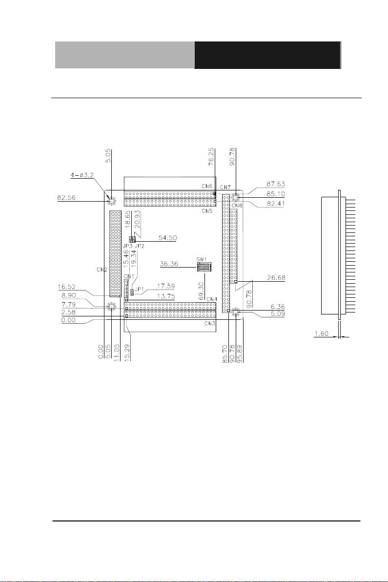
Component Side
2.2 Location and Mechanical Drawing of Connectors and Jumpers
Component Side
Chapter 2 Quick Installation Guide 2-3
Page 13
DIO Module
P F M - T 0 9 6 P
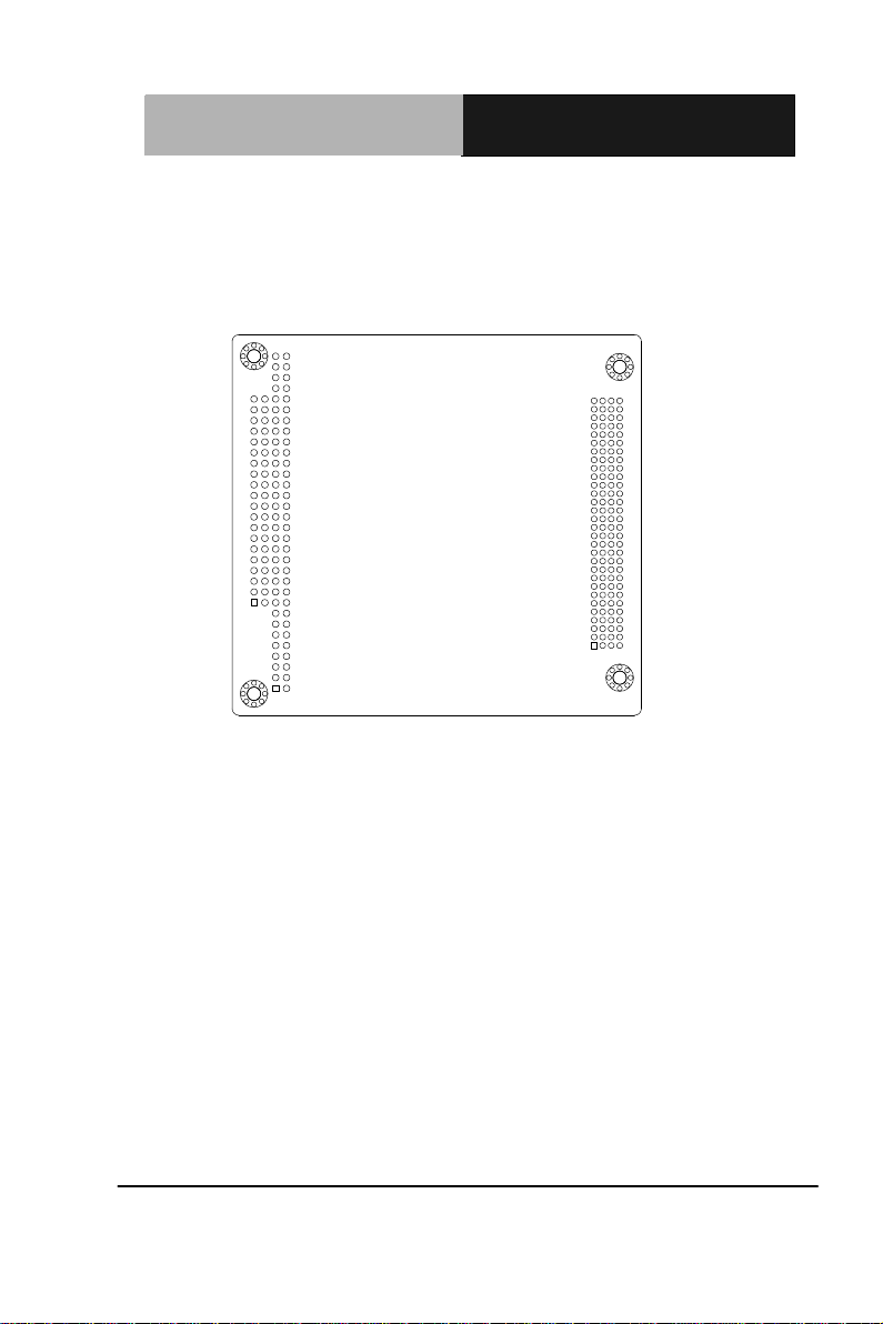
Solder Side
Solder Side
Chapter 2 Quick Installation Guide 2-4
Page 14

DIO Module
P F M - T 0 9 6 P
Label
Function
JP1
Firmware Programming Selection
JP2
PCI Resource Selection-1
JP3
PCI Resource Selection-2
SW1
BoardID Selection
Label
0B0BFunction
CN1
JTAG
CN2
PCI 104
CN3
DIO Port1
CN4
DIO Port2
CN5
DIO Port3
CN6
DIO Port4
CN7, CN8
PC/104 (Optional, Bypass PC/104 signal for
customer’s stack board request)
2.3 List of Jumpers
The board has a number of jumpers that allow you to configure your system to
suit your application.
The table below shows the function of each of the board's jumpers:
2.4 List of Connectors
The board has a number of connectors that allow you to configure your system
to suit your application. The table below shows the function of each board's
connectors:
Chapter 2 Quick Installation Guide 2-5
Page 15

DIO Module
P F M - T 0 9 6 P
1
2
3
Open Closed Closed 2-3
2.5 Setting Jumpers
You configure your card to match the needs of your application by
setting jumpers. A jumper is the simplest kind of electric switch. It
consists of two metal pins and a small metal clip (often protected by a
plastic cover) that slides over the pins to connect them. To “close” a
jumper you connect the pins with the clip.
To “open” a jumper you remove the clip. Sometimes a jumper will have
three pins, labeled 1, 2 and 3. In this case you would connect either
pins 1 and 2 or 2 and 3.
A pair of needle-nose pliers may be helpful when working with jumpers.
If you have any doubts about the best hardware configuration for your
application, contact your local distributor or sales representative before
you make any change.
Generally, you simply need a standard cable to make most
connections.
Chapter 2 Quick Installation Guide 2-6
Page 16

DIO Module
P F M - T 0 9 6 P
JP1
1B1B Function
SHORT
Enable
OPEN
Disable(default)
JP2 JP3
2B2B Function
OPEN OPEN
PCI Resource 1(IRQA,CLK0)
OPEN SHORT
PCI Resource 2(IRQB,CLK1)
SHORT OPEN
PCI Resource 3(IRQC,CLK2)
SHORT SHORT
PCI Resource 4(IRQD,CLK3)
SW1
5B5BFunction
All Off
BoardID 0(default)
Other
BoardID1~15
2.6 Firmware Programming Selection (JP1)
Enable Disable (default)
2.7 PCI Resource Selection (JP2/3)
JP2
JP3
2.8 Board ID Selection (SW1) for Multi-Board Indicate in Utility
Chapter 2 Quick Installation Guide 2-7
Page 17

DIO Module
P F M - T 0 9 6 P
Pin
Pin Name
Signal Type
Signal Level
1
+3.3V
PWR
2
GND
GND
3
TCK
CLK
4 TDO
OUT
+3.3V 5 TDI
IN
+3.3V 6 TMS
IN
Pin
Pin Name
Signal Type
Signal Level
1
PnGrpC7
IN/OUT
+5V
2
EVENT
OUT
3 PnGrpC6
IN/OUT
+5V 4 GND
GND
5 PnGrpC5
IN/OUT
+5V 6 GND
GND
7
PnGrpC4
IN/OUT
+5V
8
GND
GND
2.9 JTAG (CN1) for Firmware Programming
2.10 DIO Port 1/2/3/4 Connector (CN3/4/5/6)
Chapter 2 Quick Installation Guide 2-8
Page 18

DIO Module
P F M - T 0 9 6 P
9
PnGrpC3
IN/OUT
+5V
10
GND
GND
11
PnGrpC2
IN/OUT
+5V
12
GND
GND
13
PnGrpC1
IN/OUT
+5V
14
GND
GND
15
PnGrpC0
IN/OUT
+5V
16
GND
GND
17
PnGrpB7
IN/OUT
+5V
18
GND
GND
19
PnGrpB6
IN/OUT
+5V
20
GND
GND
21
PnGrpB5
IN/OUT
+5V
22
GND
GND
23
PnGrpB4
IN/OUT
+5V
24
GND
GND
25
PnGrpB3
IN/OUT
+5V
26
GND
GND
27
PnGrpB2
IN/OUT
+5V
28
GND
GND
29
PnGrpB1
IN/OUT
+5V
30
GND
GND
31
PnGrpB0
IN/OUT
+5V
32
GND
GND
Chapter 2 Quick Installation Guide 2-9
Page 19

DIO Module
P F M - T 0 9 6 P
33
PnGrpA7
IN/OUT
+5V
34
GND
GND
35
PnGrpA6
IN/OUT
+5V
36
GND
GND
37
PnGrpA5
IN/OUT
+5V
38
GND
GND
39
PnGrpA4
IN/OUT
+5V
40
GND
GND
41
PnGrpA3
IN/OUT
+5V
42
GND
GND
43
PnGrpA2
IN/OUT
+5V
44
GND
GND
45
PnGrpA1
IN/OUT
+5V
46
GND
GND
47
PnGrpA0
IN/OUT
+5V
48
GND
GND
49
+5V
PWR
50
EXTTRG
IN
※EVENT、EXTTRG for Counter
※PnGrp(A/B/C)(0~7) : DIO Port (1/2/3/4) Group (A/B/C) bit(0/1/2/3/4/5/6/7)
Chapter 2 Quick Installation Guide 2-10
Page 20

DIO Module
P F M - T 0 9 6 P
部件名称
有毒有害物质或元素
铅
(Pb)
汞
(Hg) 镉 (Cd)
六价铬
(Cr(VI))
多溴联苯
(PBB)
多溴二苯醚
(PBDE)
印刷电路板
及其电子组件
× ○ ○ ○ ○
○
外部信号
连接器及线材
× ○ ○ ○ ○
○
O:表示该有毒有害物质在该部件所有均质材料中的含量均在
SJ/T 11363-2006 标准规定的限量要求以下。
X:表示该有毒有害物质至少在该部件的某一均质材料中的含量超出
SJ/T 11363-2006 标准规定的限量要求。
备注:此产品所标示之环保使用期限,系指在一般正常使用状况下。
Below Table for China RoHS Requirements
产品中有毒有害物质或元素名称及含量
AAEON Main Board/ Daughter Board/ Backplane
Chapter 2 Quick Installation Guide 2-11
Page 21

DIO Module
P F M - T 0 9 6 P
Chapter
3
Driver
Installation
Chapter 3 Driver Installation 3 - 1
Page 22

DIO Module
P F M - T 0 9 6 P
Before using PFM-T096P utility, you need to install driver first.
3.1 Supported Environment
OS: Windows 7, Windows Embedded Standard 7, Windows XP, Windows
Embedded Standard 2009
3.2 For Windows 7
Chapter 3 Driver Installation 3 - 2
Page 23

DIO Module
P F M - T 0 9 6 P
Step1: Click “Update Driver” as the following graphic shows.
Chapter 3 Driver Installation 3 - 3
Page 24

DIO Module
P F M - T 0 9 6 P
Step 2: Choose “Browse my computer for driver software” and click it.
Step 3: Locate to Win7 driver folder.
Chapter 3 Driver Installation 3 - 4
Page 25

DIO Module
P F M - T 0 9 6 P
Step 4: Choose “Install this driver software anyway” and click it.
Step 5: The following dialog box pops up and the driver installation is
finished.
Chapter 3 Driver Installation 3 - 5
Page 26

DIO Module
P F M - T 0 9 6 P
Step 6: You will see the driver is properly installed.
Chapter 3 Driver Installation 3 - 6
Page 27

DIO Module
P F M - T 0 9 6 P
3.3 For Windows XP:
In Windows XP, you need to install Kernel-Mode Driver Framework first.
Step 1: Click Microsoft Kernel-Mode Driver Framework
Install-v1.9-Win2k-WinXP-Win2k3.exe.
Chapter 3 Driver Installation 3 - 7
Page 28

DIO Module
P F M - T 0 9 6 P
Step 2: Click ”Next“ and it will update your system automatically.
Chapter 3 Driver Installation 3 - 8
Page 29

DIO Module
P F M - T 0 9 6 P
Step 3: Click ”Finish“ to complete the updating.
Step 4: After installing the KDF, please install PFM-T096P driver.
Chapter 3 Driver Installation 3 - 9
Page 30

DIO Module
P F M - T 0 9 6 P
Step 5: Click “Update Driver”.
Step 6: Choose “Yes, this time only” and click “Next” to continue.
Chapter 3 Driver Installation 3 - 10
Page 31

DIO Module
P F M - T 0 9 6 P
Step 7: Choose “Install from a list or specific location (Advanced)” and click
“Next” to continue.
Step 8: Click “Browse” to locate to the Win XP driver folder. Then click
“Next”.
Chapter 3 Driver Installation 3 - 11
Page 32

DIO Module
P F M - T 0 9 6 P
Step 9: The driver installation starts.
Step 10: The following dialog box pops up and the driver installation is
finished. Click “Finish”.
Chapter 3 Driver Installation 3 - 12
Page 33

DIO Module
P F M - T 0 9 6 P
Step 11: You will see the driver is properly installed.
Chapter 3 Driver Installation 3 - 13
Page 34

DIO Module
P F M - T 0 9 6 P
3.4 Utilization of the Utility
Utility Screenshot
Chapter 3 Driver Installation 3 - 14
Page 35

DIO Module
P F M - T 0 9 6 P
Function Explanation
1. All PFM-T096P devices will list here
2. There are 4 ports in PFM-T096P (1~4)
3. Shows firmware version
4. Check this box will auto refresh DIO data and counter status
5. This box changed if there is an interrupt occurred
Chapter 3 Driver Installation 3 - 15
Page 36

DIO Module
P F M - T 0 9 6 P
1. Digital IO input settings (Checked means set in input mode)
2. Digital IO data status (Checked means High, otherwise Low)
3. There are five interrupt mode:
a. Disable: No interrupt
b. Edge: When encounter Falling or Rising edge, an interrupt
occurs
c. Level: When encounter Low or High level, interrupt occurs
repeatly
d. Change State: When DIO data status changed, an interrupt
occurs
e. Pattern Match: When pattern matching, interrupt occurs.
According these mode, here will present different function:
Edge
0: Falling, 1: Rising
Level
0: Low, 1: High
Change State
0: Enable, 1: Disable
Pattern Match
EX: Set pin interrupt mode bit7~bit0 = 0b00111000. When getting
Chapter 3 Driver Installation 3 - 16
Page 37

DIO Module
P F M - T 0 9 6 P
Data = 0b00111000, then interrupt occurs.
Counter value is 0~65535. When overflowing, interrupt occurs.
1. There are two mode:
a. Up count: counter will increase
b. Down count: counter will decrease
2. Read current counter number
3. Set count value
4. When interrupt occurring, this value decides pulse interval.
Ex. 10 = 100ms x 10 = 1000ms = 1s
Chapter 3 Driver Installation 3 - 17
Page 38

DIO Module PFM-T096P
A
Appendix
Mating Connector
Appendix A Mating Connector A - 1
Page 39

DIO Module PFM-T096P
A.1 List of Mating Connectors and Cables
The table notes mating connectors and available cables.
Connector
Label
CN3
CN4
CN5
CN6
Function
Digital I/O Molex 22-55-2501
Mating Connector
Vendor Model number
Available
Cable
AAEON
DIO
Extension
Cable
Cable P/N
1701500401
Appendix A Mating Connector A - 2
Page 40

DIO Module PFM-T096P
Appendix
B
Support Matrix
Appendix B Support Matrix B - 1
Page 41

DIO Module PFM-T096P
B.1 List of Support Matrix
For customer implement PFM-T096P with difference main board some time meet
resource issues.
Below support matrix for reference.
M/B XP Platform setting Win 7 Platform setting Remark:
1 PFM-CVS
Rev.B
2 EPIC-HD07 INT_A/B/C PASS INT_A/B/C PASS EPIC-HD07 R1.3 BIOS
3 EPIC-QM77 INT_A/C/D PASS INT_A/B/C/D PASS EPIC-QM77 R1.2 BIOS
INT_B/C/D PASS INT_A/B/C/D PASS PFM-CVSB R1.0 BIOS
Real situation depend on difference MB setting & add card to occupy the MB
resource. So above support matrix for reference only.
The jumper setting of INT for reference.
INT type JP2 JP3 Remark:
INT_A Open Open
INT_B Open Short
INT_C Short Open
INT_D Short short
Appendix B Support Matrix B - 2
 Loading...