

Page 1

CAN Bus Module PFM- C20N
PFM- C20N
PC/104 CAN Bus Module
SJA 1000 CAN Chipset
CAN 2.0 Compatible
Isolating Voltage Up to 1600VDC
PFM-C20N Manual Rev.A 1st Ed.
June 2009
Page 2

CAN Bus Module PFM- C20N
Copyright Notice
This document is copyrighted, 2009. All rights are reserved. The
original manufacturer reserves the right to make improvements
to the products described in this manual at any time without
notice.
No part of this manual may be reproduced, copied, translated,
or transmitted in any form or by any means without the prior
written permission of the original manufacturer. Information
provided in this manual is intended to be accurate and reliable.
However, the original manufacturer assumes no responsibility
for its use, or for any in fringements upon the rights of third
parties that may result from its use.
The material in this document is for product information only
and is subject to change without notice. While reasonable
efforts have been made in the preparation of this document to
assure its accuracy, AAEON assumes no liabilities resulting
from errors or omissions in this document, or from the use of the
information contained herein.
AAEON reserves the right to make changes in the product
design without notice to its users.
i
Page 3

CAN Bus Module PFM- C20N
Acknowledgments
All other products’ name or trademarks are properties of their
respective owners.
l Award is a trademark of Award Software International, Inc.
l CompactFlash™ is a trademark of the Compact Flash
Association.
l Microsoft Windows® is a registered trademark of Microsoft Corp.
l ITE is a trademark of Integrated Technology Express, Inc.
l IBM, PC/AT, PS/2, and VGA are trademarks of International
Business Machines Corporation.
l SoundBlaster is a trademark of Creative Labs, Inc.
All other product names or trademarks are properties of their
respective owners.
ii
Page 4

CAN Bus Module PFM- C20N
Packing List
Before you begin installing your card, please make sure that the
following materials have been shipped:
l Utility CD
l PFM-C20N
iii
Page 5

CAN Bus Module PFM- C20N
Contents
Chapter 1 General Information
1.1 Introduction ...........................................................1-2
1.2 Features................................................................1-2
1.3 Specifications ........................................................1-3
Chapter 2 Quick Installation Guide
2.1 Safety Precautions.................................................2-2
2.2 Location of Connectors and Jumpers ......................2-3
2.3 Mechanical Drawing...............................................2-4
2.4 List of Jumpers ......................................................2-5
2.5 List of Connectors ..................................................2-5
2.6 Setting Jumpers.....................................................2-6
2.7 CAN BUS Port 1 Termination Resistor Setup (JP1) ..2-7
2.8 Address Condition (JP2).........................................2-7
2.9 CAN BUS Port 2 Termination Resistor Setup (JP3) ..2-7
2.10 CAN BUS Port 1 IRQ Setup (JP4) .........................2-7
2.11 CAN BUS Port 2 IRQ Setup (JP5) .......................2-8
2.12 PCICLOCK & Arbitration Pins Setup (JP6) ...........2-9
2.13 PCI-104 Connector (CN1) ...................................2-9
2.14 CPLD JTAG (CN2) .............................................2-12
2.15 CAN Connector (CN3) ........................................2-12
2.16 PC/104 Connector (CN4) (Optional) ....................2-13
Chapter 3 Driver Installation
iv
Page 6

CAN Bus Module PFM- C20N
3.1 Testing with Windows XP .......................................3-2
3.2 Testing with Linux ..................................................3-9
Appendix A Mating Connector
A.1 List of Mating Connectors and Cables................. A-2
v
Page 7

CAN Bus Module PFM-C20N
Chapter
1
General
Information
Chapter 1 General Information 1- 1
Page 8

CAN Bus Module PFM-C20N
1.1 Introduction
AAEON Technology, a leading company in embedded boards
manufacturing with a full range of PC/104 CPU Modules, launches
a brand new CAN Bus Module-PFM-C20N. Its compact size and
rich functionality ensures the most cost effective and compatible
module to coincide with your existing system planning devices.
The PFM-C20N features PC/104+ expansion interfaces. It
supports Windows XP and Linux operating systems. Moreover, it
is CAN 2.0 compatible and up to 1Mbps. The PFM-C20N was
designed to enhance benefit for the Subcompact and peripheral
boards.
1.2 Features
SJA 1000 Based CAN Interface Module
CAN 2.0 Compatible, Up to 1Mbps
Onboard S witch Sele ctable CAN Termination
LEDs Indicate Diagnostics Status
Supports Win dow XP And Linux
PC/104+ Interface
Isolating Voltage Up To 1600VDC
Chapter 1 General Information 1- 2
Page 9

CAN Bus Module PFM-C20N
1.3 Specifications
Form Factor PC/104 & PCI-104 (90mm x
96mm)
CAN Chipset SJA1000
Expansion Slot PC/104 or PCI-104
Power Requirement +3.3V and +5V
Operating Temperature 32˚F~ 140˚F (0˚C ~ 60˚C)
Isolation Voltage 1600V DC
Chapter 1 General Information
1 - 3
Page 10

CAN Bus Module PFM-C20N
d
f
r
r
e
p
Chapter
2
Quick
Installation
Guide
The Quick Installation Guide is derive
rom Chapter 2 of user manual. For othe
chapters and further installation
instructions, please refer to the use
manual CD-ROM that came with th
roduct.
Chapter 2 Quick Installation Guide 2 - 1
Notice:
Printed in Taiwan, June 2009
Page 11
CANBus Module PFM-C20N
2.1 Safety Precautions
Always completely disconnect the power cord
from your board whenever you are working on
it. Do not make connections while the power is
on, because a sudden rush of power can
damage sensitive electronic components.
Always ground yourself to remove any static
charge before touching the board. Modern
electronic devices are very sensitive to static
electric charges. Use a grounding wrist strap at
all times. Place all electronic components on a
static-dissipative surface or in a static-shielded
bag when they are not in the chassis
Chapter 2 Quick Installation Guide 2 - 2
Page 12
CAN Bus Module PFM-C20N
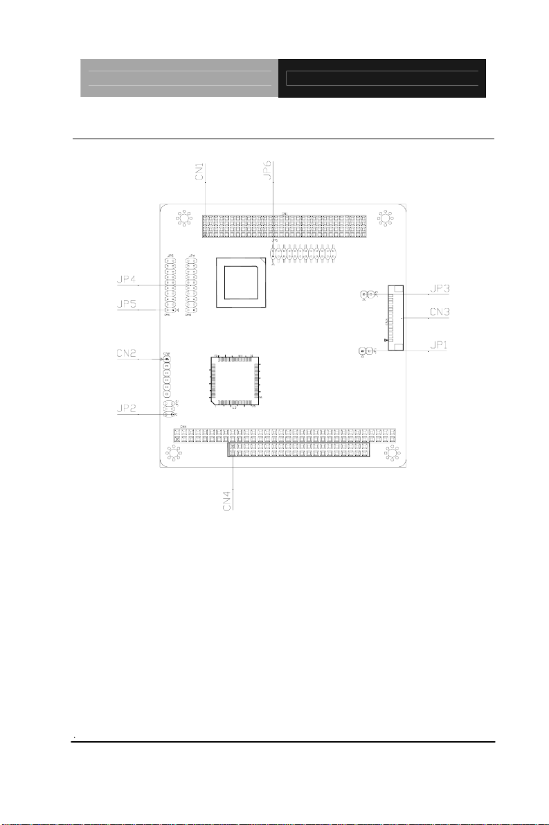
2.2 Location of Connectors and Jumpers
Chapter 2 Quick Installation Guide 2- 3
Page 13
CANBus Module PFM-C20N
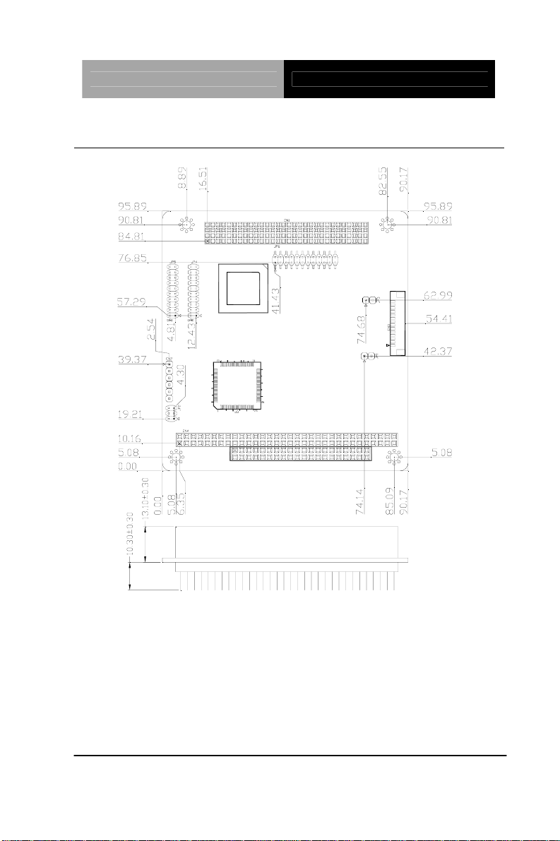
2.3 Mechanical Drawing
Chapter 2 Quick Installation Guide 2 - 4
Page 14

CAN Bus Module PFM-C20N
2.4 List of Jumpers
The board has a number of jumpers that allow you to configure your
system to suit your application. The table below shows the function
of each of the board's jumpers:
Label Function
JP1 CAN BUS Port 1 Termination Resistor Setup
JP2 Address Condition
JP3 CAN BUS Port 2 Termination Resistor Setup
JP4
JP5
JP6
CAN BUS Port 1 IRQ Setup
CAN BUS Port 2 IRQ Setup
PCICLOCK & Arbitration Pins Setup
2.5 List of Connectors
The board has a number of connectors that allow you to configure
your system to suit your application. The table below shows the
function of each board's connectors:
Label Function
CN1 PCI-104 Connector
CN2 CPLD JTAG
CN3 CAN Connector
CN4 PC/104 Connector (optional)
Chapter 2 Quick Installation Guide 2- 5
Page 15

CANBus Module PFM-C20N
2.6 Setting Jumpers
You configure your card to match the needs of your application by
setting jumpers. A jumper is the simplest kind of electric switch. It
consists of two metal pins and a small metal clip (often protected by
a plastic cover) that slides over the pins to connect them. To “close”
a jumper you connect the pins with the clip.
To “open” a jumper you remove the clip. Sometimes a jumper will
have three pins, labeled 1, 2 and 3. In this case you would connect
either pins 1 and 2 or 2 and 3.
3
2
1
Open C ed C 2-3los losed
OFF
ON ON 2-3
A pair of needle-nose pliers may be helpful when working with
jumpers. If you have any doubts about the best hardware
configuration for your application, contact your local distributor or
sales representative before you make any change. Generally, you
simply need a standard cable to make most connections.
Chapter 2 Quick Installation Guide 2 - 6
Page 16

CAN Bus Module PFM-C20N
2.7 CAN BUS Port 1 Termination Resistor Setup (JP1)
JP1 Function
1-2 Termination Resistor Setup
2.8 Address Condition (JP2)
JP2 Function
1-3,2-4 DC00
1-3,4-6 DB00
3-5,2-4 DA00 (Default)
3-5,4-6 CC00
2.9 CAN BUS Port 2 Termination Resistor Setup (JP3)
JP3 Function
1-2 Termination Resistor Setup
2.10 CAN BUS Port 1 IRQ Setup (JP4)
JP4 Function
1-2
3-4
5-6
7-8
Chapter 2 Quick Installation Guide 2- 7
IRQ3
IRQ4
IRQ5 (Default)
IRQ6
Page 17

CANBus Module PFM-C20N
9-10
IRQ7
11 -12
13-14
15-16
17-18
19-20
IRQ9
IRQ10
IRQ11
IRQ12
IRQ15
2.11 CAN BUS Port 2 IRQ Setup (JP5)
JP5 Function
1-2
3-4
5-6
7-8
9-10
11 -12
13-14
IRQ3
IRQ4
IRQ5
IRQ6
IRQ7 (Default)
IRQ9
IRQ10
15-16
17-18
19-20
IRQ11
IRQ12
IRQ15
Chapter 2 Quick Installation Guide 2 - 8
Page 18

CAN Bus Module PFM-C20N
2.12 PCICLOCK & Arbitration Pins Setup (JP6)
JP6 Function
1-2 PCI_CLK0 (Default)
3-4 PCI_CLK1
5-6 PCI_CLK2
7-8 PCI_CLK3
9-10 GNT#0 (Default)
11-12 GNT#1
13-14 GNT#2
15-16 GNT#3
17-18 REQ#0 (Default)
19-20 REQ#1
21-22 REQ#2
23-24 REQ#3
2.13 PCI-104 Connector (CN1)
Pin Signal Pin Signal
A1 GND B1 SERIRQ
A2 N.C. B2 AD2
A3 AD5 B3 GND
A4 C/BE0# B4 AD7
A5 GND B5 AD9
A6 AD11 B6 N.C.
Chapter 2 Quick Installation Guide 2- 9
Page 19

CANBus Module PFM-C20N
A7 AD14 B7 AD13
A8 +3.3V B8 C/BE1#
A9 SERR# B9 GND
A10 GND B10 PERR#
A11 STOP# B11 +3.3V
A12 +3.3V B12 TRDY#
A13 FRAME# B13 GND
A14 GND B14 AD16
A15 AD18 B15 +3.3V
A16 AD21 B16 AD20
A17 +3.3V B17 AD23
A18 IDSEL B18 GND
A19 AD24 B19 C/BE3#
A20 GND B20 AD26
A21 AD29 B21 +5V
A22 +5V B22 AD30
A23 REQ#0 B23 GND
A24 GND B24 REQ#2
A25 GNT#1 B25 N.C.
A26 +5V B26 PCI_CLK0
A27 PCI_CLK2 B27 +5V
A28 GND B28 N.C.
A29 N.C. B29 INTA#
A30 N.C. B30 REQ#3
Chapter 2 Quick Installation Guide 2 - 10
Page 20

CAN Bus Module PFM-C20N
C1 +5V D1 AD0
C2 AD1 D2 +5V
C3 AD4 D3 AD3
C4 GND D4 AD6
C5 AD8 D5 GND
C6 AD10 D6 N.C.
C7 GND D7 AD12
C8 AD15 D8 +3.3V
C9 N.C. D9 PAR
C10 +3.3V D10 N.C.
C11 LOCK# D11 GND
C12 GND D12 DEVSEL#
C13 IRDY# D13 +3.3V
C14 +3.3V D14 C/BE2#
C15 AD17 D15 GND
C16 GND D16 AD19
C17 AD22 D17 +3.3V
C18 N.C. D18 N.C.
C19 N.C. D19 N.C.
C20 AD25 D20 GND
C21 AD28 D21 AD27
C22 GND D22 AD31
C23 REQ#1 D23 N.C.
C24 +5V D24 GNT#0
Chapter 2 Quick Installation Guide 2- 11
Page 21

CANBus Module PFM-C20N
C25 GNT#2 D25 GND
C26 GND D26 PCI_CLK1
C27 PCI_CLK3 D27 GND
C28 +5V D28 RST#
C29 INTB# D29 N.C.
C30 GNT#3 D30 GND
Note: If PCI-104 Connector B1 is not SERIRQ signal, this card can not
support IRQ mode.
2.14 CPLD JTAG (CN2)
Pin Signal
1 CPLD_TMS
2 CPLD_TDI
3 CPLD_TDO
4 CPLD_TCK
5 GND
6 +5V
2.15 CAN Connector (CN3)
Pin Signal
1 +5V
2 CAN0H
Chapter 2 Quick Installation Guide 2 - 12
Page 22

CAN Bus Module PFM-C20N
3 CAN0L
4 N.C.
5 GND
6 CAN1H
7 CAN1L
8 N.C.
9 GND
10 LED_TX0
11 LED_RX0
12 LED_TX1
13 LED_RX1
14 SERIRQ
2.16 PC/104 Connector (CN4) (Optional)
Pin Signal Pin Signal
A1 N.C. B1 GND
A2 SD7 B2 RSTDRV
A3 SD6 B3 +5V
A4 SD5 B4 IRQ9
A5 SD4 B5
A6 SD3 B6
A7 SD2 B7
Chapter 2 Quick Installation Guide 2- 13
N.C
N.C
N.C
Page 23

CANBus Module PFM-C20N
A8 SD1 B8
N.C
A9 SD0 B9
A10 N.C. B10 GND
A11 AEN B11 SMEMW#
A12 SA19 B12 SMEMR#
A13 SA18 B13 IOW#
A14 SA17 B14 IOR#
A15
A16
A17
A18
A19
A20
A21
A22
A23
A24
SA16
SA15
SA14
SA13
SA12
SA11
SA10
SA9
SA8
SA7
B15
B16
B17
B18
B19
B20 N.C.
B21 IRQ7
B22 IRQ6
B23 IRQ5
B24 IRQ4
N.C
N.C.
N.C.
N.C.
N.C.
N.C.
A25
A26
A27
A28
A29
A30
A31
Chapter 2 Quick Installation Guide 2 - 14
SA6
SA5
SA4
SA3
SA2
SA1
SA0
B25 IRQ3
B26
B27
B28 BALE
B29 +5V
B30 N.C.
B31 GND
N.C.
N.C.
Page 24

CAN Bus Module PFM-C20N
A32 GND B32 GND
C0 GND D0 GND
C1
C2
C3
C4
C5
C6 SA19 D6 IRQ15
C7 SA18 D7
C8 SA17 D8
C9
C10
C11
C12
C13
C14
C15
C16
N.C.
N.C.
N.C.
N.C.
N.C.
N.C.
N.C.
N.C.
N.C.
N.C.
N.C.
N.C.
N.C.
D1
D2
D3 IRQ10
D4 IRQ11
D5 IRQ12
D9
D10
D11
D12
D13
D14
D15
D16 +5V
N.C.
N.C.
N.C.
N.C.
N.C.
N.C.
N.C.
N.C.
N.C.
N.C.
N.C.
C17
C18
C19 GND D19
Chapter 2 Quick Installation Guide 2- 15
N.C.
N.C.
D17 N.C.
D18
GND
GND
Page 25

CANBus Module PFM-C20N
Below Table for China RoHS Requirements
产品中有毒有害物质或元素名称及含量
AAEON Main Board/ Daughter Board/ Backplane
有毒有害物质或元素
部件名称
印刷电路板
及其电子组件
外部信号
连接器及线材
O:表示该有毒有害物质在该部件所有均质材料中的含量均在
SJ/T 11363-2006 标准规定的限量要求以下。
X:表示该有毒有害物质至少在该部件的某一均质材料中的含量超出
SJ/T 11363-2006 标准规定的限量要求。
备注:此产品所标示之环保使用期限,系指在一般正常使用状况下。
铅
(Pb)汞 (Hg)镉 (Cd)
× ○ ○ ○ ○ ○
× ○ ○ ○ ○ ○
六价铬
(Cr(VI))
多溴联苯
(PBB)
多溴二苯醚
(PBDE)
Chapter 2 Quick Installation Guide 2 - 16
Page 26

CAN Bus Module PFM-C20N
Chapter
3
Driver
Installation
Chapter 3 Driver Installation 3 - 1
Page 27

CAN Bus Module PFM-C20N
3.1 Testing with Windows XP
Step1: Open the “WinXP2” folder and click on “vcredist_x86.exe” to
start installing VC2008 Redistributable.
Click ”Next “ to continue.
Chapter 3 Driver Installation 3 - 2
Page 28

CAN Bus Module PFM-C20N
Check the check box and click on “Install” to follow the instruction
until the computer shows to “Finish”
Chapter 3 Driver Installation 3 - 3
Page 29

CAN Bus Module PFM-C20N
Step 2: Double click on the “Canbus.exe” file
Step 3: Click on “Configuration ”, to setup setting.
Chapter 3 Driver Installation 3 - 4
Page 30

CAN Bus Module PFM-C20N
The setting of Base Address has to be the same as Jumper
setting.
IRQ only support POLLING.
The Baud Rates of Transmit Port and Monitor Port have to be the
same.
For Mode, you may choose “Basic” or “Peli” (only Peli can transmit
“Extended frame”). The default setting of “Mode” is “Basic.”
The Acceptance Code and Mask will be varied by the “Mode” you
set. For example, “Basic” is 8 bits, Peli is 32 bits. You may
choose the default setting if the application has no specific request.
You may click on “OK” after finish setting these values.
Chapter 3 Driver Installation 3 - 5
Page 31

CAN Bus Module PFM-C20N
Step 4: The system will show the configuration information on “Port
0” and “Port 1” windows and detect the hardware status
automatically. If the status is OK, it will show
. The Monitor
Port and Transmit Port will be selectable. If the status is Fail, the
situation will be contrary.
Chapter 3 Driver Installation 3 - 6
Page 32

CAN Bus Module PFM-C20N
Step 5: Setup the “Monitor Port”: Please select “Port 0” or “Port 1”
as the Monitor Port. After setting, the pop out will ask you if the
setting is correct or not. Select “OK” to start monitoring CANBUS.
If you want to stop monitoring just click on “Stop” button.
Step 6: Setup the “Transmit Port.”:When you setup the “Transmit
Port,” please select the different port from the “Monitor Port.” If the
“Monitor Port” is “Port 0,” and the “Transmit Port” should be “Port 1.”
Otherwise, it will cause error messages.
Step 7: Data translation: Please fill out the boxes of ID, RT R and
Data in order. All the setting numbers are hexadecimal.
The ID of Standard frame (the box of Extended frame not be
Chapter 3 Driver Installation 3 - 7
Page 33

CAN Bus Module PFM-C20N
checked.) can be keyed in “0~0x7ff.” The ID of Extended frame is
“0~0x1fffffff.” (The Extended frame can be selectable in “Peli” Mode
only.)
For RTR, please key in “0” or “1.”
For Data, you may key in “0~8 Bytes” and please fill out from the
“Byte 0” to “Byte 7” in order.
After filling, please click on “Send.” There is a pop-up to show if it
is a successful transmitting or not. Meanwhile, the “Monitor Port”
will receive the information you fill and show the related information
on “Monitor Port” window. You also can click on “Clean” to erase
all data you key in.
Chapter 3 Driver Installation 3 - 8
Page 34

CAN Bus Module PFM-C20N
3.2 Testing with Linux
Step 1: Please log in as “root” when you start the computer. (If you
log in other identities, you have to command “sudo” to switch the
identity, or you cannot insert/remove module.
Below use Fedora5 as example (GENE-5315 + PFM-C20N PC-104)
Step 2: Copy the Fedora5 folder
(…/PFM-C20N/Linux/ISA/5315/FedoraCore5/Fedora5) to the root’s
home.
Open the Terminal: Applications->Accessories (Fedora4 in System
tool ->Terminal) and type command:
uname –n
[root@localhost~]# uname -n
Chapter 3 Driver Installation 3 - 9
Page 35

CAN Bus Module PFM-C20N
localhost.localdomain
※ If it does not show ”localhost.localdomain,” you have to continue
to the following step 2-A. If it shows properly, please go to Step 3.
2-A: If you get the output is “aaeon.5315” for example, please
command the following instructions.
[root@localhost~]# cd Fedora5/etc
[root@localhost etc]#cp localhost.localdomain.conf aaeon.5315.conf
[root@localhost etc]# cd ~
Step 3: Chang the setting file.
Please open the file of “Fedora5/etc/$(uname –n).conf” by Text
Editor, where the “$(unam e –n)” is the output value that you got in
step 2. For example, the output value you got in Step 2
is ”localhost.localdomain,” and the file you have to open is
“localhost.localdomain.conf.”
Chapter 3 Driver Installation 3 - 10
Page 36

CAN Bus Module PFM-C20N
Chapter 3 Driver Installation 3 - 11
Page 37

CAN Bus Module PFM-C20N
The values under Channel 0 are the default setting value of Port 0,
and the values under Channel 1 are the default setting value of
Port1.
Below use Channel 0 as example, and the same as the Channel 1.
Chipset_0: Default value is “sja1000,” please do not change it since
the IC is sja1000.
Base_0: It is a complete memory address (segment + offset), please
adjust it based on the jumper of the board. (PFM-C20N=>JP2)
2-4 4-6
1-3 DC00 DB00
3-5 DA00 CC00
If it is DA00, you have to set “0xda000.” If it is DB00, you have to set
“0xdb000.”
irq_0: Setup interrupt, you may set “0” as polling mode.
For choosing IRQ of PFM-C20N, please use the same settings of
JP4 (PORT1) and JP5 (PORT2 ). If you set “0,” please get rid of the
jumper.
The following IRQ is useful for the boards co-work with PFM-C20N.
GENE-5315: IRQ 3.4.5.7.10
EPIC-8526: IRQ 4.5
PFM-541I: IRQ 3.4.5.7.11
You may command “cat” in the Terminal to check the occupied IRQ
and avoid using the same IRQ.
[root@localhost ~]# cat /proc/interrupts
Chapter 3 Driver Installation 3 - 12
Page 38

CAN Bus Module PFM-C20N
Baud_0: can set with 125,250,500,800 and 1000
AccMask_0: Default=0xffffffff (no need to change)
AccCode_0: Default=0xffffffff (no need to change)
Timeout_0: Default=10 (no need to change)
Outc_0: Default=0xda (no need to change)
VendOpt_0: Default=a (no need to change)
IOModel_0: Default=m (no need to change)
TxSpeed_0: Default=f (no need to change)
Step 4: Setup inode: please open the terminal again
[root@localhost ~]# cd Fedora5
[root@localhost Fedora5]# make inodes
Step 5: install the driver:
[root@localhost Fedora5]# make load
Chapter 3 Driver Installation 3 - 13
Page 39

CAN Bus Module PFM-C20N
Command “grep” to check if the driver setting is the same or not.
(you may skip this step)
[root@localhost Fedora5]# grep . /proc/sys/Can/*
Step 6: Start testing the transmission, you have to create a new
terminal (FileÆOpen Terminal) on the existing terminal. And then,
command “receive” in one of the terminals to monitor CANBUS and
receive data.
[root@localhost Fedora5]# ./receive
Chapter 3 Driver Installation 3 - 14
Page 40

CAN Bus Module PFM-C20N
The default Monitor Port is “can0”. You may use the following
instruction to assign the Monitor Port to be “can1.”
[root@localhost Fedora5]# ./receive can1
And then, use the other Terminal to tran smit message.
[root@localhost Fedora5]# ./can_send 567 0x11 0x22 0x33 0x44
0x55 0x66
The following three digits of “can_send” is ID. (You can key in
000-999, decimal. The example is “567.”)
And then, you may key in 0~8 messages (0x00~0xff, hexadecimal.
The example is 0x11…)
The default Transmit Port is “can1.” You also can use the following
instruction to assign the Transmit Port.
[root@localhost Fedora5]# ./can_send –D can0 567 0x11 0x22 0x33
0x44 0x55 0x66
Adding up “-D can0” to command the Transmit Port as “can0” after
“can_send.”
If “can0” has been set to be the Monitor Port and it starts to monitor
data bus, you cannot assign “can0” as the Transmit Port.
If it is a successful transmission, the Terminal which receives data
will have shown the following message on Terminal window.
Chapter 3 Driver Installation 3 - 15
Page 41

CAN Bus Module PFM-C20N
If you want to stop the Monitor Port to monitor data bus, just let the
Terminal on focus and press ctrl+c to stop. If you did not stop
receiving data via the Monitor Port, the resource of the port will be
occupied.
Step 7: Cross check
Set can0 (Monitor Port), can1 (Transmit Port) ÅÆ can1 (Monitor
Port), can0 (Transmit Port) in terms of th e Step 6. To make sure the
transmitting and receiving is working OK on can0 and can1.
Chapter 3 Driver Installation 3 - 16
Page 42

CAN Bus Module PFM-C20N
Step 8: Testing by using different platforms
Using the two boards to test the transmitting and receiving. For
example, the can0 of GENE-5315 is the Monitor Port, and the can0
of EPIC-8526 will be the Transmit Port. Or the can1 of EPIC-8526 is
the Monitor Port, and the can0 of GENE-5315 is the Transmit Port.
In addition, you may use different systems. One is DOS system
and the other one is Windows system, or one is DOS system and the
other one is Linux system to test the transmitting and receiving
(make sure the Baud Rate setting is the same).
Step 9: Change the setting to test.
After testing, you may want to change the IRQ or Baud Rate for a
further testing. Please follow the steps below to activate.
9-1 Uninstall the driver
[root@localhost Fedora5]# /sbin/rmmod can.ko
9-2 Modify the setting based as the Step 3
9-3 Install the driver again
[root@localhost Fedora5]# make load
Chapter 3 Driver Installation 3 - 17
Page 43

CAN Bus Module PFM-C20N
A
Appendix
Mating Connecotor
Appendix A Mating Connector A - 1
Page 44

CAN Bus Module PFM-C20N
A.1 List of Mating Connectors and Cables
The table notes mating connectors and available cables.
Mating Connector Connector
Vendor Model no
CATCH A003-678 CAN Cable 1703140150
Available Cable AAEON Cable
Label
CN3
Function
CAN
Connector
P/N
Appendix A Mating Connector A - 2
 Loading...