

Page 1

Full IP66 Stainless
Panel PC
A F P - 6 1 5 2
AFP-6152
®
Intel
Full IP66 Stainless Panel PC
15” TFT LCD with 7H Surface
AtomTM D525 Processor
AFP-6152 Manual 2nd Ed
Oct. 2013
Page 2

Full IP66 Stainless
Panel PC
A F P - 6 1 5 2
Copyright Notice
This document is copyrighted, 2013. All rights are reserved. The
original manufacturer reserves the right to make improvements to
the products described in this manual at any time without notice.
No part of this manual may be reproduced, copied, translated, or
transmitted in any form or by any means without the prior written
permission of the original manufacturer. Information provided in
this manual is intended to be accurate and reliable. However, the
original manufacturer assumes no responsibility for its use, or for
any infringements upon the rights of third parties that may result
from its use.
The material in this document is for product information only and is
subject to change without notice. While reasonable efforts have
been made in the preparation of this document to assure its
accuracy, AAEON assumes no liabilities resulting from errors or
omissions in this document, or from the use of the information
contained herein.
AAEON reserves the right to make changes in the product design
without notice to its users.
i
Page 3

Full IP66 Stainless
Panel PC
A F P - 6 1 5 2
Acknowledgments
All other products’ name or trademarks are properties of their
respective owners.
Award is a trademark of Award Software International, Inc.
Intel®, and AtomTM are trademarks of Intel® Corporation.
Microsoft Windows® is a registered trademark of Microsoft
Corp.
IBM, PC/AT, PS/2, and VGA are trademarks of International
Business Machines Corporation.
All other product names or trademarks are properties of their
respective owners.
ii
Page 4

Full IP66 Stainless
Panel PC
A F P - 6 1 5 2
Packing List
Before you begin operating your PC, please make sure that the
following materials are enclosed:
1 USB Cable with 2 USB Waterproof Connectors
2 COM Cables with water proof Connectors
1 waterproof Connecter for DC–in (Female)
1 waterproof Connecter for LAN (optional)
1 CD-ROM for manual (in PDF format)
1 AFP-6152 Full IP66 Stainless Panel PC
If any of these items should be missing or damaged, please contact
your distributor or sales representative immediately.
iii
Page 5

Full IP66 Stainless
Panel PC
A F P - 6 1 5 2
Safety & Warranty
1. Read these safety instructions carefully.
2. Keep this user's manual for later reference.
3. Disconnect this equipment from any DC outlet before cleaning.
Do not use liquid or spray detergents for cleaning. Use a damp
cloth.
4. For pluggable equipment, the power outlet must be installed near
the equipment and must be easily accessible.
5. Keep this equipment away from humidity.
6. Put this equipment on a firm surface during installation. Dropping
it or letting it fall could cause damage.
7. The openings on the enclosure are for air convection. Protect the
equipment from overheating. DO NOT COVER THE OPENINGS.
8. Make sure the voltage of the power source is correct before
connecting the equipment to the power outlet.
9. Position the power cord so that people cannot step on it. Do not
place anything over the power cord.
10. All cautions and warnings on the equipment should be noted.
11. If the equipment is not used for a long time, disconnect it from the
power source to avoid damage by transient over-voltage.
12. Never pour any liquid into an opening. This could cause fire or
electrical shock.
13. Never open the equipment. For safety reasons, only qualified
service personnel should open the equipment.
14. If any of the following situations arises, get the equipment
checked by service personnel:
a. The power cord or plug is damaged.
b. Liquid has penetrated into the equipment.
iv
Page 6
Full IP66 Stainless
Panel PC
A F P - 6 1 5 2
c. The equipment has been exposed to moisture.
d. The equipment does not work well, or you cannot get it
to work according to the user’s manual.
e. The equipment has been dropped and damaged.
f. The equipment has obvious signs of breakage.
15. DO NOT LEAVE THIS EQUIPMENT IN AN ENVIRONMENT
WHERE THE STORAGE TEMPERATURE IS BELOW -20°C
(-4°F) OR ABOVE 70°C (140°F). IT MAY DAMAGE THE
EQUIPMENT.
16. DO NOT OPEN the sealed Enclosure /case of equipment. Once
enclosure is disassembled without approval, it will lead in
abnormal operating of water proof gel. For Guarantee of water
proof function, please make sure configuration/ peripheral
(HDD,RAM, peripherals) has been confirmed to install before
shipping.
FCC
This device complies with Part 15 FCC Rules.
Operation is subject to the following two
conditions: (1) this device may not cause
harmful interference, and (2) this device must
accept any interference received including
interference that may cause undesired
operation.
Caution:
There is a danger of explosion if the battery is incorrectly replaced.
Replace only with the same or equivalent type recommended by the
manufacturer. Dispose of used batteries according to the
manufacturer’s instructions and your local government’s recycling or
disposal directives.
v
Page 7
Full IP66 Stainless
Panel PC
A F P - 6 1 5 2
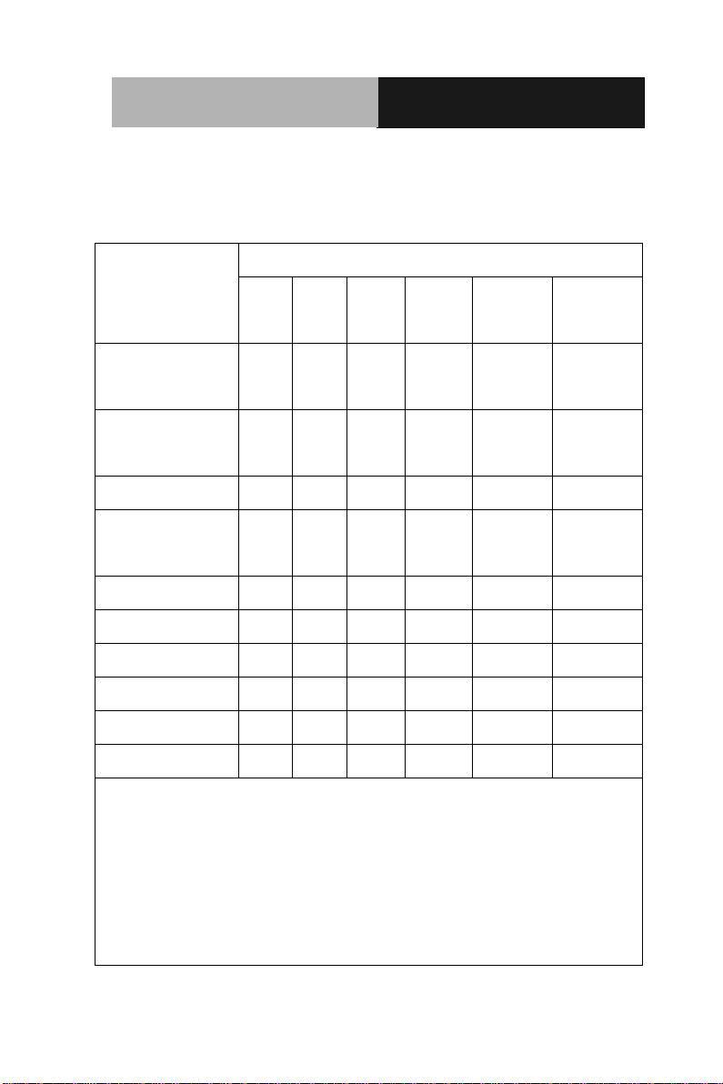
部件名称
有毒有害物质或元素
铅
(Pb)
汞
(Hg) 镉 (Cd)
六价铬
(Cr(VI))
多溴联苯
(PBB)
多溴二苯醚
(PBDE)
印刷电路板
及其电子组件
× ○ ○ ○ ○
○
外部信号
连接器及线材
× ○ ○ ○ ○
○
外壳
× ○ ○ ○ ○
○
中央处理器
与内存
× ○ ○ ○ ○
○
硬盘
× ○ ○ ○ ○ ○ 液晶模块
× ○ ○ ○ ○ ○ 光驱
× ○ ○ ○ ○ ○ 触控模块
× ○ ○ ○ ○ ○ 电源
× ○ ○ ○ ○
○
O:表示该有毒有害物质在该部件所有均质材料中的含量均在
SJ/T 11363-2006 标准规定的限量要求以下。
X:表示该有毒有害物质至少在该部件的某一均质材料中的含量超出
SJ/T 11363-2006 标准规定的限量要求。
备注:
一、此产品所标示之环保使用期限,系指在一般正常使用状况下。
二、上述部件物质中央处理器、内存、硬盘、光驱、触控模块为选购品。
Below Table for China RoHS Requirements
产品中有毒有害物质或元素名称及含量
AAEON Panel PC/ Workstation
vi
Page 8

Full IP66 Stainless
Panel PC
A F P - 6 1 5 2
Contents
Chapter 1 General Information
1.1 Introduction ................................................................ 1-2
1.2 Features .................................................................... 1-3
1.3 Specification .............................................................. 1-4
1.4 Dimension ................................................................. 1-7
Chapter 2 Hardware Installation
2.1 USB 1/2 Connecter ................................................... 2-2
2.2 COM 1 Connector for RS232 .................................... 2-2
2.3 COM 2 Connector for RS232/RS422/RS485 ............ 2-3
2.4 DC-IN 9~30V Connector ........................................... 2-4
Chapter 3 AMI BIOS set up
3.1 System Test and Initialization ................................... 3-2
3.2 AMI BIOS Setup ........................................................ 3-3
Chapter 4 Driver Installation
4.1 Installation ................................................................. 4-3
Appendix FAQ
A.1 FAQ ........................................................................ A-2
vii
Page 9

Full IP66 Stainless
Panel PC
AFP-6152
Chapter
1
General
Information
Chapter 1 General Information 1- 1
Page 10

Full IP66 Stainless
Panel PC
AFP-6152
1.1 Introduction
AFP-6152 Full IP66 Stainless Panel PC is a high-performance
computing and completely fan-less solution for applications in the
Food industry, because AFP-6152 has the full IP-66 protection,
316L stainless and 7H Hardness surface. AFP-6152 comes with
®
Intel
AtomTM D525 processor, 15” TFT LCD Display with LED
Backlight 316L Stainless, 7H hardness surface, Sealing enclosure
(IP66 certificated) and Water proof I/O connectors for Ethernet ,
multi-COM port, audio and USB interfaces.
Besides, for system integrators, a simple, complete, compact and
highly integrated system helps you smoothly build an industrial
grade solution into your applications. By this concept, AFP-6152 is
design with valuable features (listed in next section) to serve
various field of markets such as Factory and Outdoor, especially
Food industry.
Chapter 1 General Information 1- 2
Page 11

Full IP66 Stainless
Panel PC
AFP-6152
1.2 Features
15" 1024 x 768 TFT LCD with LED Backlight, 400 nits
Glass-Film-Glass touch with 7H hardness surface
IP66 Protection Certificated
Supports Windows XP, Windows 7, Linux Fedora
Wide Operating Temperature Range: -20
o
C~60oC (With
HDD)
Mini PCIe x 1
Waterproof Lockable I/O: Standard M12 Waterproof
Connector
Chapter 1 General Information 1-3
Page 12

Full IP66 Stainless
Panel PC
AFP-6152
1.3 Specification
System
CPU Onboard Intel
Processor
System Memory DDR3 SODIMM, Max. 2GB
LCD / CRT Controller Intel
M12 water proof I/O Port RS-232 x 2
®
ICH8M
USB Cable with 2 USB connectors x 1
Power Input
10/100/1000Base-TX RJ-45
Storage Disk Drive Internal Type II Compact Flash™/
Internal Anti-vibration 2.5” Hard Disk
OS Support Windows
64bits ), Lunux Fedora
®
AtomTM D525 1.8 GHz
®
XP, Windows® 7 ( 32bits and
Mechanical
Construction 316L Stainless
Mounting VESA 75/100mm holes
Dimension 9.65” (W) x 7.2” (H) x 2.37” (D)
(410mm x 336mm x 59.6mm)
Net Weight 13.2 lb (6Kg)
Gross Weight 16.5 lb (7.5Kg)
Chapter 1 General Information 1- 4
Page 13

Full IP66 Stainless
Panel PC
AFP-6152
Environmental
Operating Temperature -4 ~1℉ 22 (℉ -20 ~5℃ 0);℃
With W/T Hard Disk drive
Storage Temperature -4 ~158 (℉℉-20 ~70 )℃℃
Operating Humidity 5% to 90%@40 , non℃ -condensing
Vibration Random Operation 1G, 5-500Hz
Shock 20G peak acceleration (11 msec.
duration)
EMC CE/FCC Class A
Power Supply Input: DC 9~30V
LCD
Display Type 15” Color TFT LCD
Max. Resolution 1024 x 768
Max. Colors 16.2M colors
Dot Size 0.297mm x 0.297mm
Luminance 400 nits
Viewing Angle 160
o
(H) x 140 o (V)
Touch Screen
Type 5-Wire Glass-Film-Glass touch with 7H
hardness surface
Light Transmission 80% ± 3% (5-wire analog resistive)
74% (8-wire analog resistive)
Lifetime 10 million activations
Chapter 1 General Information 1-5
Page 14

Full IP66 Stainless
Panel PC
AFP-6152
Note: All AAEON's LCD products are manufactured with High precision
technology. However, in all LCD panels there maybe a small number of
defective pixels that do not change color. This is a normal occurrence for
all LCD displays from all manufacturers and should not be noticeable or
objectionable under normal operation. AAEON qualify the LCD panel
following industry standard: total 7 dead pixels on a screen or if there are
3 within 1 inch square area of each other on the display.
Chapter 1 General Information 1- 6
Page 15

Full IP66 Stainless
Panel PC
1.4 Dimension
390.00
56.50
28.00
AFP-6152
84.50
321.94
324.00
221.94
Unit: mm
Chapter 1 General Information 1-7
Page 16

Full IP66 Stainless
Panel PC
VESA 75/100 mount holes
Connectors
AFP-6152
Chapter 1 General Information 1- 8
Page 17

Full IP66 Stainless
Panel PC
AFP-6152
Chapter
2
Hardware
Inst
Chapter 2 Quick Installation Guide 2-1
allation
Page 18

Full IP66 Stainless
Panel PC
AFP-6152
2.1 USB 1/2 Connecter
Pin Signal Pin Signal
1 USB1 V+ 2 USB0 V+
3 USB D0+ 4 USB D05 USB0 GND 6 USB D1+
7 USB D1- 8 USB1 GND
2.2 COM1 Connector for RS-232
Pin Signal Pin Signal
1 DCD 2 RXD
3 TXD 4 DTR
5 GND 6 DSR
7 RTS 8 CTS
Chapter 2 Quick Installation Guide 2 - 2
Page 19

Full IP66 Stainless
Panel PC
AFP-6152
2.3 COM2 Connector for RS-232/422/485
RS-232
Pin Signal Pin Signal
1 DCD 2 RXD
3 TXD 4 DTR
5 GND 6 DSR
7 RTS 8 CTS
RS-422
Pin Signal Pin Signal
1 TXD- 2 RXD+
3 TXD+ 4 RXD-
RS-485
Pin Signal Pin Signal
1 TXD- 2 NC
3 TXD+ 4 NC
Chapter 2 Quick Installation Guide
2 - 3
Page 20

Full IP66 Stainless
Panel PC
2.4 DC-IN 9~30V Connecter
Pin Signal Pin Signal
1 DC V+ 2 N/A
3 GND 4 NC
AFP-6152
Chapter 2 Quick Installation Guide 2 - 4
Page 21

Full IP66 Stainless
Panel PC
AFP-6152
Chapter
3
AMI
BIOS Setup
Chapter 3 AMI BIOS Setup 3-1
Page 22

Full IP66 Stainless
Panel PC
AFP-6152
3.1 System Test and Initialization
These routines test and initialize board hardware. If the routines
encounter an error during the tests, you will either hear a few short
beeps or see an error message on the screen. There are two kinds
of errors: fatal and non-fatal. The system can usually continue the
boot up sequence with non-fatal errors.
System configuration verification
These routines check the current system configuration against the
values stored in the CMOS memory. If they do not match, the
program outputs an error message. You will then need to run the
BIOS setup program to set the configuration information in memory.
There are three situations in which you will need to change the
CMOS settings:
1. You are starting your system for the first time
2. You have changed the hardware attached to your system
3. The CMOS memory has lost power and the configuration
information has been erased.
The AFP-6152 CMOS me mory has an integral lithium battery
backup for data retention. However, you will need to replace the
complete unit when it finally runs down.
Chapter 3 AMI BIOS Setup 3-2
Page 23

Full IP66 Stainless
Panel PC
AFP-6152
3.2 AMI BIOS Setup
AMI BIOS ROM has a built-in Setup program that allows users to
modify the basic system configuration. This type of information is
stored in battery-backed CMOS RAM so that it retains the Setup
information when the power is turned off.
Entering Setup
Power on the computer and press <Del> or <F2> immediately. This
will allow you to enter Setup.
Main
Set the date, use tab to switch between date elements.
Advanced
Advanced BIOS Features Setup including TPM, ACPI, etc.
Chipset
Host bridge parameters.
Boot
Enables/disable quiet boot option.
Security
Set setup administrator password.
Save&Exit
Exit system setup after saving the changes.
Chapter 3 AMI BIOS Setup 3-3
Page 24

Full IP66 Stainless
Panel PC
AFP-6152
Chapter
4
Driver
Inst
allation
.
Chapter 4 Driver Installation 4 -1
Page 25

Full IP66 Stainless
Panel PC
AFP-6152
The AFP-6152 comes with an AutoRun CD-ROM that contains all
drivers and utilities that can help you to install the driver
automatically.
Insert the driver CD, the driver CD-title will auto start and show the
installation guide. If not, please follow the sequence below to install
the drivers.
Follow the sequence below to install the drivers:
Step 1 – Install Chipset Driver
Step 2 – Inst all VGA Driver
Step 3 – Install LAN Driver
Step 4 – Install Touch Driver (Optional)
Step 5 – Install Rapid Storage Driver (Optional)
Please read instructions below for further detailed installations.
Chapter 4 Driver Installation 4 -2
Page 26

Full IP66 Stainless
Panel PC
AFP-6152
4.1 Installation:
Insert the AFP-6152 CD-ROM into the CD-ROM drive. And install
the drivers from Step 1 to Step 5 in order.
Step 1 – Install Chipset Driver
1. Click on the STEP1-CHIPSET folder and select the OS
folder your system is
2. Double click on the .exe file located in each OS folder
3. Follow the instructions that the window shows
4. The system will help you install the driver automatically
Step 2 – Inst all VGA Driver
1. Click on the STEP2-VGA folder and select the OS folder
your system is
2. Double click on the Setup.exe file located in each OS
folder
3. Follow the instructions that the window shows
4. The system will help you install the driver automatically
Step 3 –Install LAN Driver
1. Click on the STEP3-LAN folder and select the OS folder
your system is
2. Double click on the .exe file located in each OS folder
3. Follow the instructions that the window shows
4. The system will help you install the driver automatically
Chapter 4 Driver Installation 4 -3
Page 27

Full IP66 Stainless
Panel PC
AFP-6152
Step 4 –Install Touch Driver (Optional)
1. Click on the STEP4-TOUCH (Option) folder and select
the OS folder your system is
2. Double click on the .exe located in each OS folder
3. Follow the instructions that the window shows
4. The system will help you install the driver automatically
Step 5 –Install Rapid Storage Driver (Optional)
1. Click on the STEP5-RAPID STORAGE (Option) folder
and double click on the setup.exe
2. Follow the instructions that the window shows
3. The system will help you install the driver automatically
Chapter 4 Driver Installation 4 -4
Page 28

Full IP66 Stainless
Panel PC
A F P - 6 1 5 2
Appendix
A
FAQ
Appendix A FAQ A-1
Page 29

Full IP66 Stainless
Panel PC
A F P - 6 1 5 2
A.1 FAQ
1. Installing Windows 2000 from a USB CD-ROM Drive May
Cause a "Stop 0x7B" Error
Answer:
Only if you install Windows 2000 SP3 version, the error will be
automatically corrected.
Categorized List of Fixes in Windows 2000 Service Pack 3 (SP3)
http://support.microsoft.com/default.aspx?scid=%2fsupport%2fserv
icepacks%2fwindows%2f2000%2fsp3fixlist.asp
Q294820 - Installing Windows 2000 from a USB CD-ROM Drive
May Cause a "Stop 0x7B" Error
http://support.microsoft.com/default.aspx?scid=kb;en-us;294820
PSS ID Number: 294820
Article Last Modified on 5/28/2003
The information in this article applies to:
Microsoft Windows 2000 Server SP1
Microsoft Windows 2000 Server SP2
Microsoft Windows 2000 Advanced Server SP1
Microsoft Windows 2000 Advanced Server SP2
Microsoft Windows 2000 Professional SP1
Microsoft Windows 2000 Professional SP2
Appendix A FAQ A-2
Page 30

Full IP66 Stainless
Panel PC
A F P - 6 1 5 2
This article was previously published under Q294820
SYMPTOMS
If you are using a Universal Serial Bus (USB) CD-ROM drive to
install Windows 2000 on certain legacy-free computers, you may
receive a "Stop 0x0000007B" Inaccessible_boot_device error
message while booting from the installation CD. Because many
legacy-free computers do not have a standard CD-ROM drive or
floppy disk drive, the USB CD-ROM drive may be the only method
for installing or recovering Windows.
CAUSE
Windows 2000 Setup does not support certain USB CD-ROM
drives as bootable devices. This causes error message during the
Text-mode portion of Setup.
RESOLUTION
Please contact your computer manufacturer for information about
obtaining updated Windows 2000 Setup disks that you can use to
boot your computer with a USB CD-ROM device.
STATUS
Microsoft has confirmed that this is a problem in the Microsoft
products that are listed at the beginning of this article.
Appendix A FAQ A-3
Page 31

Full IP66 Stainless
Panel PC
A F P - 6 1 5 2
2. What does the Day/Night Mode button actually do?
Answer:
Day mode is the highest brigntness for out door use, Night mode is
lowest one for power saving and navigation safty.
3. What type of anti-glare treatment are you putting onto your
touch screen and what is the LCD brightness reduction with
this treatment?
Answer:
We use Low Reflection touch screen with Anti-Refelctive surface
which incorporates "circular polarizer" filems inside.It is new
technology of Touch panel , which has several layers of films,
applied to reduce the amount of reflection back into the users eye
(Reflectivity:1.5 ± 1%)and increase "contrast ratio" of display in
outdoor environment.
4. How to use M12 LAN Connector?
Step 1: Peel off the release paper of gasket of RJ-45 plug cable set and
stick it to its body.
Appendix A FAQ A-4
Page 32

Full IP66 Stainless
Panel PC
A F P - 6 1 5 2
Step 2: Cut off the present RJ-45 plug.
Step 3: Put all parts of RJ45 plug cable set through cable in order.
Step 4: Install and crimp a new RJ-45 plug.
Step 5: Insert RJ-45 plug into the socket and mount cable set’s body. Make
sure RJ-45’s latch is in place.
Appendix A FAQ A-5
Page 33

Full IP66 Stainless
Panel PC
A F P - 6 1 5 2
latch is in place
sealer is in place
Step 6: Lock and tighten the nut of RJ-45 plug.
Step 7: Screw on the plastic rear nut a little bit for later locking. Make sure
sealer is in place.
Appendix A FAQ A-6
Page 34

Full IP66 Stainless
Panel PC
A F P - 6 1 5 2
press hard
lock the plastic rear nut
Step 8: Press the cable hard inward and lock the plastic rear nut tightly at
the same time.
Step 9: Tighten the plastic rear nut more to make sure the cable is secured
from being moved by any unexpected force.
Appendix A FAQ A-7
 Loading...